1
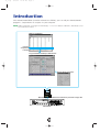
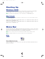
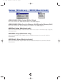
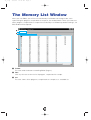
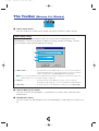
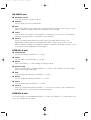
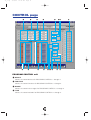
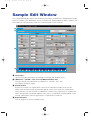
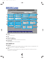
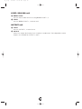
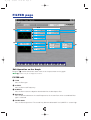
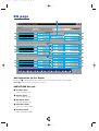
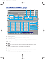
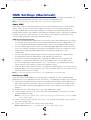
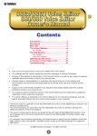
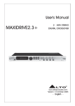
se_e.qx
9/16/99
12:14 PM
Page 1
Contents
Introduction ..................................................2
Starting Up ..................................................3
Menu Bar ......................................................4
The Memory List Window............................6
The Toolbar ......................................................7
The Program Edit Window ..........................8
The Sample Edit Window ..........................13
The Toolbar ....................................................24
OMS Settings (Macintosh) ................................25
Troubleshooting ........................................27
•
The software and this owner’s manual are exclusive copyrights of Yamaha Corporation.
•
Copying of the software or reproduction of this manual in whole or in part by any means is expressly
forbidden without the written consent of the manufacturer.
•
Yamaha makes no representations or warranties with regard to the use of the software and
documentation and cannot be held responsible for the results of the use of this manual and the
software.
•
Copying of the commercially available music sequence data and/or digital audio files is strictly
prohibited except for your personal use.
•
The company names and product names in this Owner’s Manual are the trademarks or registered
trademarks of their respective companies.
•
The screen displays as illustrated in this Owner’s Manual are for instructional purposes, and may
appear somewhat different from the screens which appear on your computer.
This owner’s manual is applicable to both the A5000 Editor and the A4000 Editor (for both Windows and
Macintosh).
The screen illustrations are mainly taken from the A5000 Editor for Windows, although and differences
between versions are explained.
This owner’s manual assumes that you are already familiar with basic Windows/Macintosh operation. If you
are not,please refer to the owner’s manual which came with your Windows/Mac OS software before using
A5000/A4000 Editor.
For information about hardware requirements, the interconnection of devices and the installation of the
A5000/A4000 Editor software, refer to the separate “Installation Manual” as well as the Owner’s Manual for
the respective MIDI device.
© 1999 Yamaha Corporation. All rights reserved.
1
se_e.qx
9/16/99
12:14 PM
Page 2
Introduction
With A5000/A4000 Editor (hereafter referred to as Editor), you can edit your A5000/A4000’s
programs, sample banks or samples via your computer.
n Editor for Windows is a plug-in for XGworks(lite). To use Voice Editor for Windows, XGworks(lite) must
be installed beforehand.
Memory List Window
Program,
sample bank
or sample
Program Edit Window/Sample Edit Window
Set the effects parameters
MIDI Cable
Transmit/Receive bulk data or parameter change data
A5000/A4000
2
se_e.qx
9/16/99
12:14 PM
Page 3
Starting Up
Windows 95/98
If you have a A5000, you can start Editor by starting XGworks and choosing “A5000 Editor”
from the “Plug-in” menu. If you have an A4000, choose “A4000 Editor” instead.
n Set the MIDI Out port appropriately to send the edited data to the A5000/A4000 (Page 7).
Macintosh
n If you are using Voice Editor on a Macintosh computer, open the “Chooser” from the Apple menu and
turn off “Apple Talk.”
If you have an A5000, open the “A5000 Editor” folder in the “YAMAHA Voice Editor” folder and
double-click the “A5000Editor” icon.
If you have an A4000, open the “A4000 Editor” folder in the “YAMAHA Voice Editor” folder and
double-click the “A4000Editor” icon.
Menu Bar
The Menu Bar holds various editing and setup functions/commands in its menus. Click each of
the menu names to open their pull-down menu, and choose the function/command you wish to
apply. Those functions/commands which are unavailable are grayed out.
n The most commonly-used menus in the Menu Bar are available as buttons in Editor's toolbar.
n To use Editor for Windows, refer to the documentation that came with XGworks(lite).
File
Macintosh
Close (Macintosh only)
Closes the window. This is the same as the “Close” box in the Title Bar. (Not effective for the
Memory List Window.)
3
se_e.qx
9/16/99
12:14 PM
Page 4
Edit
Windows
Macintosh
A5000/A4000 Editor Edit (Edit)
This is the same as the “Edit Window” button in the toolbar (Page 7).
4
se_e.qx
9/16/99
12:14 PM
Page 5
Setup (Windows) / MIDI (Macintosh)
Windows
Macintosh
A5000/A4000 Editor Setup (Editor Setup)
This is the same as the “Editor Setup” button in the toolbar (Page 7).
A5000/A4000 Editor Receive Memory List (Receive Memory List)
This is the same as the “Receive Memory List” button in the toolbar (Page 7).
OMS Port Setup (Macintosh only)
Opens the OMS Port Setup window for Editor. Refer to the section “OMS Port Setup” (Page 26)
for further details.
OMS MIDI Setup (Macintosh only)
Opens the OMS MIDI Setup window. Refer to the documentation that came with OMS for
further details.
OMS Studio Setup (Macintosh only)
Opens the OMS Studio Setup window. Refer to the documentation that came with OMS for
further details.
5
se_e.qx
9/16/99
12:14 PM
Page 6
The Memory List Window
When you start Editor, you will first see the Memory List Window consisting of tabs, each
representing the program, sample bank or sample in your A5000/A4000. When you choose to
edit a program, sample bank or sample from the Memory List Window by double-clicking it, the
Edit Window will be opened.
1
2
3
1 Toolbar
This area holds the buttons controlling Editor (Page 7).
2 Tabs
Click any of these to view the list of program, sample bank or sample.
3 List
This area shows all the programs, sample banks or samples as a scrollable list.
6
se_e.qx
9/16/99
12:14 PM
Page 7
The Toolbar
(Memory List Window)
1
2 3
1 “Editor Setup” button
Click this to open the “Editor Setup” dialog and specify the MIDI Out port settings.
“Editor Setup” Dialog
This is where you set up the Editor to allow the transmission of edited data to your
A5000/A4000. Click the [OK] button to apply the settings and quit the dialog. Click the
[Cancel] button to quit without applying the settings.
1
2
3
1 “MIDI Out Port:” ..........................Click this and choose the MIDI Out port. You can use the Voice Editor to
control and edit the device connected to this port. Select the port which
has been assigned to your A5000/A4000 within XGworks(lite).
n If you are using a Macintosh, the MIDI Out Port setting is assigned in the OMS Port Setup. For
further details, see section “OMS Settings.” (Page 27)
2 “MIDI Ch:” ..................................Click this and choose the MIDI Out channel. This is used when
monitoring sounds using the on-screen keyboard in the Edit Windows.
3 “Device No.:” ..............................Click this and choose the MIDI device number of your A5000/A4000.
2 “Receive Memory List” button
Click this to receive all the programs, sample banks or samples data in bulk from your
A5000/A4000.
3 “Edit Window” button
Click this to open the Edit Window for the selected program, sample bank or sample in the
list.
7
se_e.qx
9/16/99
12:14 PM
Page 8
Program Edit Window
The Program Edit Window allows you to edit the parameters related to the A5000/A4000
programs. The edited data are transmitted to the A5000/A4000 via MIDI in realtime. For
information on each parameter, refer to the A5000/A4000 Owner’s Manual.
1 The Toolbar
This area includes the buttons controlling the Edit Window (P.24).
2 “EFFECT/SETUP” and “CONTROL” Tabs
Click the tabs to switch between the “EFFECT/SETUP” and “CONTROL” pages.
3 Keyboard button
Click or drag this to hear the edited results.
1
2
3
8
se_e.qx
9/16/99
12:14 PM
Page 9
EFFECT/SETUP page
3
@
!
$%
^
&
*
1
2
#
4
5
6
7
8
9
)
1 PROGRAM LEVEL
Sets the program volume.
2 TRANSPOSE
Sets the pitch of the entire program in semitone intervals.
3 SAMPLE LFO S/H SPEED
Sets the frequency of the LFO S/H waveform. Higher values produce higher speed.
PROGRAM PORTAMENTO unit
4 MODE (MONO)
Selects the PROGRAM PORTAMENTO mode. The mode indicated in parenthesis is
effective only when the sample that uses the PROGRAM PORTAMENTO is in the mono
mode.
5 RATE/TIME
Sets the PROGRAM PORTAMENTO rate or time.
9
se_e.qx
9/16/99
12:14 PM
Page 10
AD INPUT unit
6 AD INPUT ON/OFF
Turns the AD INPUT function on or off.
7 SOURCE
Sets the input source of the AD INPUT.
8 PAN
Sets the pan position of the input signal via the AD INPUT function. If the source is set to
2Mono, separate settings for INPUT L and INPUT R are available.
9 LEVEL
Sets the levels for OUTPUT 1 and OUTPUT 2, respectively. If the source is set to 2Mono,
separate settings for INPUT L and INPUT R are available.
) OUTPUT
Selects the output destination of the input signal via the AD INPUT function. Two
independent stereo outputs are available for OUTPUT 1 and 2. If the source is set to
2Mono, separate settings are available for INPUT L and INPUT R for both OUTPUT 1 and
2, for a total of four independent stereo outputs.
EFFECT1-3 unit
! CONNECTION
Sets the connections for EFFECT 1, 2 and 3.
@ LEVEL
Sets the input levels for EFFECT 1, 2 and 3.
# DETAIL
Opens the EFFECT 1, 2 and 3 dialog for editing in detail.
$ EFFECT TYPE
Shows the effect types assigned to EFFECT 1, 2 and 3. Click the boxes to see the effect
type list and assign other effects.
% PAN
Sets the output pan positions for EFFECT 1, 2 and 3.
^ WIDTH
Sets the output pan widths for EFFECT 1, 2 and 3.
& LEVEL
Sets the output levels for EFFECT 1, 2 and 3.
* OUTPUT
Selects the output destination for EFFECT 1, 2 and 3. This function is not available for an
effect block which is connected to another effect block.
EFFECT4-6 unit
The same functions are provided for EFFECT 4, 5 and 6 as for EFFECT 1, 2 and 3 above. This
unit is not available for the A4000.
10
se_e.qx
9/16/99
12:14 PM
Page 11
CONTROL page
1
5
2
6
3
5
4
6
7
)! @ %
89
^
#
PROGRAM CONTROL unit
1 DEVICE
Selects the control devices for PROGRAM CONTROLs 1 through 4.
2 FUNCTION
Selects the control functions for PROGRAM CONTROLs 1 through 4.
3 RANGE
Selects the control value ranges for PROGRAM CONTROLs 1 through 4.
4 TYPE
Selects the control methods for PROGRAM CONTROLs 1 through 4.
11
$
se_e.qx
9/16/99
12:14 PM
Page 12
CHANNEL SETUP unit
5 CTRL RESET
Determines whether the control value is reset or maintained for each MIDI channel when
the program is switched by a program change message or other mean. Select ON to reset
or NO to maintain. MIDI channels B01 through B16 are not available on the A4000.
6 NOTE ON TYPE
Selects the type of playback which will occur when note-on messages are received for
each MIDI channel. MIDI channels B01 through B16 are not available on the A4000.
PROGRAM LFO unit
7 WAVE
Selects the PROGRAM LFO waveform. The selected waveform is used to modulate the
sound in synchronization with the received MIDI clock and the playback tempo.
8 CYCLE
Selects the note type corresponding to the one PROGRAM LFO cycle.
9 INIT PHASE
Selects the initial phase of the PROGRAM LFO.
) SYNC
Selects the PROGRAM LFO synchronization method. MANUAL allows the PROGRAM LFO
to be synchronized to the specified tempo, and MIDI allows the PROGRAM LFO to be
synchronized to a received MIDI clock.
! TEMPO
Sets the tempo for MANUAL synchronization. This has no effect when MIDI synchronization
is selected.
@ RESET CH
Specifies the MIDI channel via which a received note-on message will initialize the phase
of the PROGRAM LFO when MANUAL synchronization is selected. This has no effect when
MIDI synchronization is selected.
# NOTE
Specifies the note number which will initialize the phase of PROGRAM LFO. This has no
effect when MIDI synchronization is selected.
$ VALUE
Sets the values for STEP 1 through 16 of the step wave waveform. This has no effect on
waves other than the step wave.
% SLOPE
Selects the method by which the step wave steps will be smoothly connected. This has no
effect on waves other than the step wave.
^ TOTAL STEPS
Sets the total number of steps for the step wave. Values for steps beyond the total step
number have no effect.
12
se_e.qx
9/16/99
12:14 PM
Page 13
Sample Edit Window
The Sample Edit Window allows you to edit the parameters related to the A5000/A4000 sample
banks or samples. The edited data are transmitted to the A5000/A4000 via MIDI in realtime. For
information on each parameter, refer to the A5000/A4000 Owner’s Manual.
1
2
3
4
1 The Toolbar
This area includes the buttons controlling the Sample Edit Window (P.24).
2 “MAP/OUT”, “FILTER”, “EG” and “LFO/MIDI/CONTROL” tabs
Click the tabs to switch between the “MAP/OUT”, “FILTER”, “EG” and
“LFO/MIDI/CONTROL” pages.
3 ON/OFF button
Determines whether the sample bank values or the individual sample values will be
effective for each parameter or parameter group. Select ON to make the sample bank
values effective, or OFF to make the inbdividual sample values effective (the sample bank
values are ignored). This button appears only when a sample bank is being edited. If you
change a parameter value this parameter is automatically turned ON.
4 Keyboard button
Click or drag this to hear the edited results.
13
se_e.qx
9/16/99
12:14 PM
Page 14
MAP/OUT page
1
9
&
2
)
*
3
!
4
@
#
5
#
6
7
8
$
(
º
º
¡
¡
™
™
£
£
¢
¢
∞
∞
%
^
1 LEVEL
Sets the volume level.
2 PAN
Sets the pan position.
3 VELOCITY SENSITIVITY
Sets the velocity sensitivity to control the volume level.
4 POLY/MONO
Selects polyphonic or mono playback.
KEY RANGE unit
5 ORIGINAL
Specifies the original key note number at which the sample sounds at its original pitch. This
cannot be set when a sample bank is being edited.
6 LOW
Sets the lowest key note number for the sample’s key range. This cannot be set when a
sample bank is being edited.
14
se_e.qx
9/16/99
12:14 PM
Page 15
7 HIGH
Sets the highest key note number for the sample’s key range. This cannot be set when a
sample bank is being edited.
8 KEY X-FADE
Turns key crossfade OFF or ON.
PITCH unit
9 COARSE
Adjusts the sample’s pitch in semitone intervals.
) FINE
Fine-tunes the sample’s pitch. This cannot be set when a sample bank is being edited.
! RANDOM
Sets the amount of random pitch variation.
@ FIXED
Determines whether the sample sounds at the same pitch over the entire key range or not.
VELOCITY RANGE unit
# HIGH
Sets the maximum velocity for the velocity range.
$ LOW
Sets the minimum velocity for the velocity range.
% HIGH X-FADE
Sets the crossfade depth at the maximum velocity.
^ LOW X-FADE
Sets the crossfade depth at the minimum velocity.
EXPAND unit
& DETUNE
Sets the detune depth.
* DEPHASE
Sets the dephase depth.
( WIDTH
Sets the pan width for the detuned or dephased sound.
SAMPLE PORTAMENTO unit
º MODE (MONO)
Selects the sample portamento mode. The mode in parentheses is effective only when the
sample or sample bank is set to the mono mode.
¡ RATE/TIME
Sets the portamento rate or time.
15
se_e.qx
9/16/99
12:14 PM
Page 16
LEVEL SCALING unit
™ BREAK POINT
Sets the note number for level scaling BREAK POINT 1, 2.
£ LEVEL
Sets the BREAK POINT 1, 2 volume level.
OUTPUT unit
¢ LEVEL
Sets the OUTPUT 1, 2 volume level.
∞ OUTPUT
Selects the output destination of the sample or sample bank. Two independent stereo
outputs are available for OUTPUT 1 and 2.
16
se_e.qx
9/16/99
12:14 PM
Page 17
FILTER page
1
2
6
3
7
4
5
8
9
@
)
#
!
Edit Operation on the Graph
Drag the “■” marker toward the arrow mark to set the parameter on the graph.
n “■” markers may be overlapped sometimes.
FILTER unit
1 TYPE
Sets the filter type.
2 CUTOFF
Sets the filter cutoff frequency.
3 Q/WIDTH
Sets the filter resonance depth or band width for the band pass filter.
4 DISTANCE
Sets the distance between the cutoff frequencies of the two filters when a combined filter
type is selected.
5 FILTER GAIN
Sets the filter output level. The sound may become distorted if the Q/WIDTH is set too high.
17
se_e.qx
9/16/99
12:14 PM
Page 18
6 VELOCITY→CUTOFF
Determines how the cutoff frequency changes in response to velocity.
7 VELOCITY→Q/WIDTH
Determines how the Q/WIDTH value changes in response to velocity.
EQ unit
8 TYPE
Sets the EQ type.
9 FREQUENCY
Sets the EQ frequency point.
) GAIN
Sets the gain at the selected frequency point.
! WIDTH
Sets the band width. This may not be available for some filter types.
FILTER SCALING unit
@ BREAK POINT
Sets the filter scaling BREAK POINT 1, 2 note.
# CUTOFF
Sets the amount of cutoff increase or decrease at BREAK POINT 1, 2.
18
se_e.qx
9/16/99
12:14 PM
Page 19
EG page
4
1
5
2
6
3
7
!
%
8
@
^
9
#
&
)
$
*
™
™
§
(
£
£
¶
º
¢
¢
•
¡
∞
∞
ª
Edit Operation on the Graph
Drag the “■” marker toward the arrow mark to set the parameter on the graph.
n “■” markers may be overlapped sometimes.
AMPLITUDE EG unit
1 ATTACK RATE
Sets the attack rate.
2 DECAY RATE
Sets the decay rate.
3 RELEASE RATE
Sets the release rate.
4 SUSTAIN LEVEL
Sets the sustain level.
5 ATTACK MODE
Sets the attack mode.
19
se_e.qx
9/16/99
12:14 PM
Page 20
6 RATE SCALING
Determines how the amplitude EG rates vary according to the note played.
7 VELOCITY→RATE
Determines how the amplitude EG rates vary in response to the velocity of the played note.
FILTER EG unit
8 ATTACK RATE
Sets the rate at which the cutoff frequency moves from its initial level (at note on) to the
attack level.
9 DECAY RATE
Sets the rate at which the cutoff frequency moves from the attack level to the sustain level.
) RELEASE RATE
Sets the rate at which the cutoff frequency moves from the sustain level to the release level
following note off.
! INIT LEVEL
Sets the cutoff frequency offset value at the time of note on.
@ ATTACK LEVEL
Sets the cutoff frequency offset value at the attack level.
# SUSTAIN LEVEL
Sets the cutoff frequency offset value at the sustain level.
$ RELEASE LEVEL
Sets the cutoff frequency offset value at the release level.
% RATE SCALING
Determines how the filter EG rates vary according to the note played.
^ VELOCITY→RATE
Determines how the filter EG rates vary in response to the velocity of the played note.
& VELOCITY→ATTACK LEVEL
Sets the first velocity-sensitivity value for the filter EG’s initial level and attack level.
* VELOCITY→LEVEL
Sets the general velocity sensitivity for all filter EG levels.
PITCH EG unit
( ATTACK RATE
Sets the rate at which the pitch moves from its initial level (at note on) to the attack level.
º DECAY RATE
Sets the rate at which the pitch moves from the attack level to the sustain level.
¡ RELEASE RATE
Sets the rate at which the pitch moves from the sustain level to the release level following
note off.
™ INIT LEVEL
Sets the pitch offset value at the time of note on.
20
se_e.qx
9/16/99
12:14 PM
Page 21
£ ATTACK LEVEL
Sets the pitch offset value at the attack level.
¢ SUSTAIN LEVEL
Sets the pitch offset value at the sustain level.
∞ RELEASE LEVEL
Sets the pitch offset value at the release level.
§ RATE SCALING
Determines how the pitch EG rates vary according to the note played.
¶ VELOCITY→RATE
Determines how the pitch EG rates vary in response to the velocity of the played note.
• VELOCITY→LEVEL
Sets the general velocity sensitivity for pitch EG levels.
ª PITCH EG RANGE
Sets the range for pitch EG pitch variation.
21
se_e.qx
9/16/99
12:14 PM
Page 22
LFO/MIDI/CONTROL page
7
1
2
3
4
5
6
8
9
!
)
#
^
&
@
*
(
$
%
1 RECEIVE CHANNEL
Sets the MIDI receive channel on which the sample will sound.
2 ALTERNATE GROUP
Used to eliminate inappropriate simultaneous sounding of multiple drum instruments.
LFO unit
3 WAVE
Selects the LFO waveform. The selected waveform is used to modulate the sound.
4 SPEED
Sets the LFO frequency. Higher values produce faster modulation.
5 KEY SYNC
Determines whether the LFO waveform is reset or maintained at the time of note on.
6 DELAY
Sets the delay time to the beginning of LFO modulation after note on.
22
se_e.qx
9/16/99
12:14 PM
Page 23
7 PITCH MODULATION DEPTH
Sets the degree by which the pitch is modulated by the LFO waveform.
8 FILTER MODULATION DEPTH
Sets the degree by which the filter’s cutoff frequency is modulated by the LFO waveform.
9 AMPLITUDE MODULATION DEPTH
Sets the degree by which the amplitude is modulated by the LFO waveform.
) PITCH MODULATION PHASE INVERT
Inverts the waveform used to modulate the pitch.
! FILTER MODULATION PHASE INVERT
Inverts the waveform used to modulate the filter.
SAMPLE CONTROL unit
@ DEVICE
Selects the control devices for PROGRAM CONTROLs 1 through 6.
# FUNCTION
Selects the control functions for PROGRAM CONTROLs 1 through 6.
$ RANGE
Selects the control value ranges for PROGRAM CONTROLs 1 through 6.
% TYPE
Selects the control methods for PROGRAM CONTROLs 1 through 6.
PITCH BEND unit
^ PITCH BEND TYPE
Sets the pitch bend control method.
& PITCH BEND RANGE
Sets the pitch bend control range.
VELOCITY unit
* VELOCITY LOW LIMIT
Sets the minimum note velocity. When a note on message with a lower velocity is received,
the actual playback velocity will be automatically raised to the value set here.
( VELOCITY OFFSET
Sets the offset value which is applied to all received velocities to raise or lower them by the
same amount.
23
se_e.qx
9/16/99
12:14 PM
Page 24
The Toolbar
(Edit Window)
This area holds the buttons controlling the Edit Window.
1 2
1 “Editor Setup” button
See item 1 in “The Toolbar” of “The Memory List Window” (Page 7).
2 “Memory List” button
Click this to bring the Memory List Window back into view (Page 6).
24
se_e.qx
9/16/99
12:14 PM
Page 25
OMS Settings (Macintosh)
The A5000/A4000 Editor software uses OMS (Open Music System) for MIDI input/output. To
use the A5000/A4000 Editor software, OMS must be installed beforehand.
n For information about installing OMS, refer to the separate Installation Manual.
About OMS
Voice Editor uses the OMS (Open Music System) to transfer MIDI data to an external MIDI
device. OMS is a system extension that goes in the Mac OS System folder, designed to
manage the MIDI data stream (input & output) in a computer, to enable MIDI data transfer
between MIDI software and hardware attached to the computer. OMS is a de facto standard of
the MIDI environment under the Mac OS, and various music software manufacturers have
released OMS-compatible sequencer and other software.
OMS has the following merits:
• As OMS-compatible MIDI applications communicate with various MIDI devices via OMS, it
is no longer necessary for you to set up multiple MIDI drivers for those applications. Thus,
you can avoid conflicts between different drivers with the same purpose (MIDI control).
•
Once a Studio Setup is read in OMS, any OMS-compatible application will be aware of it,
even if you need to reconfigure the routing of the MIDI data stream or change the current
Studio Setup. OMS-compatible applications will commonly recognize the new
configuration.
•
You can have different Studio Setups to choose one from,to switch to a different MIDI
routing (patches between MIDI devices and software) fast and easily.
•
Every time the OMS Setup application is opened, any MIDI device connected to the
computer is automatically detected, and its icon appears with a current MIDI status
(channel number, port number, patches, etc.). Once devices are configured with OMS
Setup, however, you need not care too much about the status.
•
OMS can drive various MIDI interfaces, including the standard type (16 channels) and the
multi-port type (16 channels per port). If you use a multi-port type, you can control over 16
channels simultaneously via OMS.
n For more information about OMS features, see the READ ME file included with OMS.
Setting up OMS
Setup files for the A5000/A4000 have already been created for use with the A5000/A4000
Editor; please use the appropriate file for your device. The following example is for the A5000.
1. Interconnect the MIDI interface device connected to the Macintosh and the MIDI IN-A or
MIDI IN-B terminal of the A5000. Select the terminal you use (MIDI IN-A or MIDI IN-B) in
the UTILITY/MIDI function/SysEx page/Receive Port. (This setting is not needed for the
A4000.)
2. Double-click the “OMS Setup” icon in the “OMS Application” folder.
3. Choose “Open” from the “File” menu and select “A5000-Modem” from within the “OMS
setup for YAMAHA” folder.
n If you are using a computer with no modem port (such as the Performa series), look in the “A5000Printer” folder instead.
4. Choose “Make Current” from the “File” menu. The setup for your A5000 is now saved as
the current studio setup.
5. Choose “Quit” from the “File” menu to close OMS Setup.
n A5000/A4000 Editor is not compatible with versions of OMS earlier than 2.0.
25
se_e.qx
9/16/99
12:14 PM
Page 26
OMS Port Setup
Having set up OMS, you now need to start up the A5000/A4000 Editor and set the OMS ports.
1. First, start up the A5000/A4000 Editor by double-clicking its icon.
n If AppleTalk is enabled, you will get an alert message. Click “OFF.” It will take some time for
AppleTalk to be disabled.
2. Choose “OMS Port Setup” from the A5000/A4000 Editor’s “MIDI” menu, then select the port
settings. In the following example, the tone generator is an A5000 and its setups are
applied to OMS.
MIDI In:
Select “A5000.”
MIDI Out: Select “A5000.”
3. Click [OK] to close OMS Port Setup.
26
se_e.qx
9/16/99
12:14 PM
Page 27
Troubleshooting
If you encounter problems such as no sound output or abnormal behavior, verify the connections
before checking the following. If you are using the A5000/A4000 Editor for Windows, refer to the
XGworks(lite) owner’s manual too.
<Macintosh>
<Windows>
The printer port is not recognized.
•
The printer port will not be recognized if AppleTalk
is ON. Note that with some Macintosh models,
AppleTalk is automatically enabled when starting
up.
A5000/A4000 Editor is not available in the Plug-in
menu.
•
Is the A5000/A4000 Editor installed in the same
folder as XGworks(lite)? If not, reinstall A5000/
A4000 Editor.
•
Verify that the “Printer” checkbox has been checked
in the OMS MIDI Setup window.
Bulk data is not received.
•
Is the MIDI In set correctly in the System Setup of
XGworks?
The modem port is not recognized.
•
On some Macintosh models such as the Performa
series, the modem port cannot be used and only the
printer port is available.
•
•
MIDI Out port is not available in Editor Setup.
•
The MIDI Out port in Editor Setup can be chosen
from the MIDI Out ports in the System Setup of
XGworks(lite). Check the MIDI Out settings in the
System Setup of XGworks(lite).
Verify that the “Modem” checkbox has been
checked in the OMS MIDI Setup window.
No MIDI In/Out data
•
•
•
In the OMS Port Setup, is MIDI In/Out set to
“unknown”? If you change the OMS ports or setup,
the OMS output ports have to be set accordingly in
A5000/A4000 Editor’s OMS Port Setup window.
Choose the appropriate receiving device.
<Windows / Macintosh>
Sound does not change when using knobs or sliders.
•
Are the MIDI Out port and Device Number set
correctly in the Editor Setup? (Page 7)
Is OMS using the same port as that connected to
the cable? Open the OMS MIDI Setup window and
verify that the checkbox for the relevant port has
been checked.
Parameter change data is not transmitted.
•
Are the MIDI Out port and Device Number set
correctly in the Editor Setup? (Page 7)
If the port and setup assignments are frequently
altered, OMS may be unable to easily recognize the
serial port. Reboot the Macintosh, set up OMS
correctly, then start up the A5000/A4000 Editor.
No sound heard when clicking on-screen keyboard in
Edit Window.
•
Is the MIDI Ch. set correctly in the Editor Setup?
(Page 7)
Memory List data are not received.
•
Open the OMS Port Setup window and check that
the MIDI In has been properly assigned (Page 26).
•
Open the Editor Setup Dialog and check that the
Device No. has been properly assigned (Page 7).
Open the Editor Setup Dialog and check that the
Device No. has been properly assigned (Page 7).
27