1
B756–01–880 Issue F
Instruction Manual
EXT Split Flow Compound Turbomolecular Pumps
Description
24 Volt EXT Compound Turbomolecular Pumps:
EXT200/200H
EXT200/200Hi
EXT70/200H
EXT200/200H GCMS (Reversed Body)
EXT200/200H LCMS (Reversed Body)
24 Volt EXT system (comprising Compound Turbomolecular Pump and EXDC160):
EXT200/200H
EXT200/200Hi
EXT70/200H
EXT200/200H GCMS
EXT200/200H GCMS (Reversed Body)
EXT200/200H LCMS (Reversed Body)
80 Volt EXT Compound Turbomolecular Pumps:
EXT200/200H
EXT200/200Hi
EXT70/200H
EXT200/200H ICPMS
80 Volt EXT system (comprising Compound Turbomolecular Pump and EXDC160)
EXT200/200H
EXT200/200Hi
EXT70/200H
Item Number
B756-01-991
B756-02-991
B756-03-991
B756-41-991
B756-43-991
B756-21-991
B756-22-991
B756-23-991
B756-40-991
B756-42-991
B756-44-991
B756-01-000
B756-02-000
B756-03-000
B756-30-000
B756-21-000
B756-22-000
B756-23-000
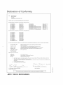
Declaration
of Conformity
Wq
BOC Edwa.ds,
ManorRoyal,
Crawley,
West SussexRH102LW UK
declareunderour soleresponsibiliry
rharrhe product(s)
SPLIT-FLOW
EXTCompo'rnd
Turbomolecular
Pump(2aVokt:
EXT200/200H
EXT200/200Hi
EXTTO/2OOH
EXT200/200Hi
EXT200/200H
EXT200/200Hi
EXTTOi2OOH
875641-991
8756-02-991
875643-991
8756-05-991
t
*
8756-21-991
*
s7s6"22-991
8756-73-9911'
EXT200/200Hi
8756-25-991
+*
EXT200/200H
8756-26-991
t*
*
EXT200/200H
GCI4S
8756-40-991
EXT200/200HGcl'as(Reversedbody)
875641-991
t
EXT200i200HGC|'4S(Reversedbody)
s75642-991t*
EXT200/200H
LCMS(R€versed
body) 875643-991+
EXT?00/200HLC|'4S(ReveEedbody)
875644-991*1'
SPLIT-FLOWEXT CompoundTurbomolecular
Pump(80 Volts)l
EXT200/200H
EXT200/200Hi
EXr70t200H
EXT200/200H
EXT200/200H
EXT200/200H
EXT200/200Hi
EXTTO/2OOH
EXT200/200Hi
EXT200/200H
EXT200/200H
TCPMS
8755-01400
8756-02-000
8756{3"000
8756"05-000
t
8756{7-000
8756-21-000
8756-22-000
B756-23-000
8756-2s-000
t
8756-28-000
t
8756-30-000
to which thls declaratioh relates is in conformity with the following standard(s) or other normative document(s):
EN 1SO12100-2:2003
Safet',ofmachinery.Basicconcep6,genenl principalsfor design.
EN610101:2001
Safetyrequiremenrs
for €lectricalequipm€ntfor measur€ment,
contol andlaboraroryuse.Genemlreouirements.'
Compressorsandvacuumpumps.Safetyrequirementi.Vacuumpumps.
Electricalequipmentfor measurement,
controlandlaborator)use.
EMC requirements.
EN1012-2:1996
E N 6 1 3 2 61:9 9 7
+ A1: 1998+ A2: 2001
(lndustrialLo.ation,
ClassB Emissions)
followinS the provisions of:
2006t95tEC
2004/108/EC
98t37tEC
t
'
*
+
Low Vohate Directive.
Electromagnetlc
CompatibilityDir€ctive.
MachinerySafetyDirecdve.t
Cartridsevariantsare incompletemachines.
Theyare not coveredbythe f4achinerySafetyDirectiveunderthis
Declarationot Conformity,allother Direc.ivesapply.
The pLrmps
complywirh EN61010-1r
2001wh€n installedin ac.ordancewith the instructionmanualsupplied
wjrh
IncludingEXDC160Controller.
Includinr€xtendedvenrpo adapror.
Br-, A-C^€=s;
B. D. Brewster,TechnicolMonager,
EurgessH,ll Products
i-'\ I (-(-.
Dote ond Plo.e
Thisproducthosbeenfionufoctuted
undeto quohtysystemregistered
to l5o900t
.W
BOC EDWARDS
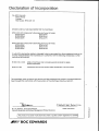
Declaration
of Incorporation
We, BOC Edwards,
Manor Royal,
Crawley,
West Sussex RH10 2LW, UK
declare
under our sole responsibility
that the machine(s)
SPLIT-FLOW EXT Compound
EXT200/200Hi
EXT200/200Hi
EXT200/200H
Turbomolecular
Pump (24 Volts):
B756-05-991
B756-25-991
B756-26-991
SPLIT-FLOW EXT Compound
EXT200/200H
EXT200/200Hi
EXT200/200H
Turbomolecular
Pump (80 Volts):
B756-O5-000
B756-25-000
B756-28-000
to which this declaration
function independently.
normative
document(s)
relates is intended to be incorporated
into other
The machine(s) is inconformity
with the following
equipment
standard(s)
EN ISO12100-2: 2003
Safety of machinery. Basic concepts, general principals for design.
Technical principals.
EN1012-2: 1996
Compressors and vacuum pumps. Safety requirements. Vacuum pumps
and not to
or other
The machine(s)
must not be put into service until the equipment
into which it is incorporated
been brought into conformity
with the provisions of the Machinery Directive, 98/37/EC.
has
i(
,
_\~~
I') ~~\lAiW~S
Dr J. D. Watson, Technical Director
Vacuum Equipment and Exhaust Management
1J~1.*-.sJJot""'-
Date and Place
~"
!Ii
Product Divisions
0
'"
'"
6
This product
,j~~'~BOC
has been
manufactured
under a quality
system registered
to ISO900 1
EDWARDS
,,"',,",
"""."-~..,.,
"
-'"'"'
.
~
'"
a.
This page intentionally blank.
EXT Split Flow Compound Turbomolecular Pumps
CONTENTS
Section
Page
INTRODUCTION
Scope and definitions
1
1
2
2.1
2.2
2.3
2.4
2.5
TECHNICAL DATA
General
Pumping media
Vent gas specification and vent control data
Water-cooling
Materials exposed to gases pumped
3
3
3
4
4
7
3
3.1
3.2
3.3
3.3.1
3.3.2
3.3.3
3.3.4
3.3.5
3.4
3.5
3.5.1
3.5.2
3.6
3.6.1
3.6.2
3.6.3
INSTALLATION
Unpack and inspect
Typical installation
Connection to the vacuum system
Mechanical fixing
Inlet-screens (supplied fitted)
Inlet connection and orientation
Backing connection
Interstage connection (Hi pump variants only)
Vent options, vent valve connection and control
Electrical installation
EXDC Controllers
EXC Controllers
Cooling
Introduction
Forced-air cooling
Water-cooling
11
11
12
13
13
14
14
15
16
16
17
17
17
18
18
18
18
4
4.1
4.2
4.3
4.3.1
4.3.2
OPERATION
Start-up
Shut-down
Safety interlocks and control system
EXDC Controllers
EXC Controllers
19
19
20
20
20
20
5
5.1
5.2
5.3
5.4
5.5
MAINTENANCE
Introduction
Bearing maintenance
Rotor life
Cleaning the pump
Fault finding
21
21
21
21
22
22
6
6.1
6.2
STORAGE AND DISPOSAL
Storage
Disposal
27
27
27
dcs/7506/0307
1
1.1
Mar 07
i
Issue F
PAGE
i
EXT Split Flow Compound Turbomolecular Pumps
PAGE
ii
7
7.1
7.2
7.3
7.3.1
7.3.2
7.3.3
7.4
7.4.1
7.4.2
7.4.3
7.4.4
7.4.5
7.4.6
7.4.7
7.4.8
SERVICE, SPARES AND ACCESSORIES
Introduction
Service
Spares
ISX Inlet-Screens
Inlet-strainer (interstage pumps only)
Inlet-flange seals
Accessories
Installation
EXDC Drive Modules
EXC Controllers
Pump-to-controller cables
EXT Water cooling block assembly
TAV Vent-valve and vent-port adaptor
ACX Air-Cooler
VRX Vent-restrictor
29
29
29
29
29
29
30
30
30
30
30
31
31
31
31
32
INDEX
33
ILLUSTRATIONS
Figure
1
2
3
4
5
6
7
8
Issue F
Page
Dimensions of the EXT 200/200H Split Flow Pump system (units in mm)
Dimensions of the EXT 200/200H GCMS Split Flow Pump system (units in mm)
Dimensions of the EXT 200/200H ICPMS Split Flow Pump system (units in mm)
Dimensions of the EXT 200/200H GCMS/LCMS (reversed body)
A typical vacuum system using a Turbomolecular pump
Correct installation of inlet screen
Mounting attitude range of an EXT Split Flow Pump
Installation of optional accessories
ii
7
8
9
10
12
14
15
32
Mar 07
EXT Split Flow Compound Turbomolecular Pumps
TABLES
Table
1
2
3
4
5
6
7
8
9
10
11
12
13
14
15
16
17
Mar 07
Page
General
3
Vent gas and vent control data
4
Water-cooling
4
Technical data
5
List of items supplied
13
Vent-restrictor orifice diameter (with atmospheric pressure at the inlet of the vent-valve) 16
Fault finding
23
ISX Inlet-screens
29
Inlet-strainer (interstage pumps only)
29
Inlet-flange seals
30
EXDC Drive modules
30
EXC Controllers
30
Pump-to-controller cable
31
EXT Water cooling block assembly
31
TAV Vent-valve and vent-port adaptor
31
ACX Air-cooler
31
VRX Vent-restrictor
32
iii
Issue F
PAGE
iii
EXT Split Flow Compound Turbomolecular Pumps
PAGE
iv
This page intentionally blank.
Issue F
iv
Mar 07
EXT Split Flow Compound Turbomolecular Pumps
1
INTRODUCTION
1.1
Scope and definitions
PAGE
1
The EXT Split Flow Pumps are designed for use with a BOC Edwards EXDC or EXC Controller. Read
this manual and the instruction manual supplied with your controller before you attempt to install or
operate the equipment. The controller manual contains details of electrical installation.
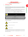
Important safety information in this manual is highlighted as WARNING and CAUTION instructions;
please obey these instructions. The use of WARNINGS and CAUTIONS is defined below.
WARNING
Warnings are given where failure to observe the instruction could result in injury or death
to people.
CAUTION
Cautions are given where failure to observe the instruction could result in damage to the equipment,
associated equipment and process.
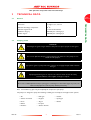
In accordance with the recommendations of EN61010, the following warning symbols may appear on
the pump or its accessories:
Warning – refer to accompanying documentation.
Warning – risk of electric shock.
Warning – hot surfaces.
The units used throughout this manual conform to the SI international system of units of measurement.
Also throughout this manual, wherever flow rates are specified, the abbreviation 'sccm' is used to mean
standard cm3min-1: this is a flow of 1cm3min-1 at an ambient temperature of 0 oC and a pressure of
1013 mbar (1.013 x 10⁵ Pa).
Mar 07
1
Issue F
INTRODUCTION
This manual provides installation, operation, maintenance and storage instructions for the BOC Edwards
EXT70/200H and EXT200/200H Split Flow Compound Molecular Pumps, abbreviated to EXT Split Flow
Pump in the remainder of this manual. Covering both the 24 V and 80 V variants. Please read and follow
all instructions in this manual.
EXT Split Flow Compound Turbomolecular Pumps
PAGE
2
INTRODUCTION
This page intentionally blank.
Issue F
2
Mar 07
EXT Split Flow Compound Turbomolecular Pumps
2
TECHNICAL DATA
2.1
General
PAGE
3
See Table 4
Dimensions
See Figures 1, 2, 3 and 4
Maximum inlet-flange temperature
70 oC
Maximum magnetic field
3.5 mT Horizontal field
Installation category
EN61010 part 1, Category 1
Pollution degree
EN61010 part 1, Category 2
TECHNICAL DATA
Performance
Table 1 - General
2.2
Pumping media
WARNING
Vent dangerous gases and gas mixtures safely. Do not expose people to these gases.
WARNING
Do not use Split Flow Pumps to pump explosive gas mixtures as the pumps are not
suitable for this purpose.
WARNING
If pyrophoric gases are pumped then the customer must supply adequate dilution with an
inert gas.
WARNING
If pumping hazardous gases or vapours, the customer must observe the safety
recommendations of the supplier of the gas or vapour.
CAUTION
Do not use an EXT Split Flow Pump to pump gases containing more than 20% oxygen. If you do, the
lubricant will polymerise and the pump will fail prematurely.
Note: Concentrations of gases may be modified by the compression of the pump.
The pumps are designed to pump the following residual gases normally used in high-vacuum systems:
Mar 07
• Air
• Nitrogen
• Helium
• Carbon monoxide
• Krypton
• Hydrogen
• Neon
• Argon
• Butane
• Ethane
• Propane
• Methane
• Carbon dioxide
3
Issue F
EXT Split Flow Compound Turbomolecular Pumps
You can use the pumps to pump oxygen and water vapour, subject to the following conditions:
PAGE
4
•
Oxygen – The oxygen concentration must be less than 20% by volume.
•
Water vapour - You must ensure that vapour does not condense inside the pump; refer to
Section 3.6.3.
TECHNICAL DATA
If you wish to pump a gas not in the list above, contact your supplier for advice. If you do not contact
your supplier, you may invalidate the warranty on the pump. The pumps are not suitable for pumping
aggressive or corrosive gases.
2.3
Vent gas specification and vent control data
Although the pump may be vented to atmosphere, high relative humidity of the air may greatly increase
the subsequent pump-down time. To reduce pump-down times you should vent the pump with dry, clean
gases.
Vent gas
Dry air, nitrogen, argon or other inert gases
Maximum dew point at atmospheric pressure -22 oC
Maximum size of particulate
1 µm
Maximum concentration of oil
0.1 parts per million
Time for rotational speed to reach 50%
> 15 sec
Table 2 - Vent gas and vent control data
2.4
Water-cooling
The following cooling-water specification corresponds to a typical high-quality drinking water
specification. Check with your water supply authority if you are in doubt about the quality of your supply.
Quality
Mechanically and optically clean with no deposits
or turbidity
pH value
6.0 to 8.0
Maximum calcium carbonate concentration
75 parts per million
Maximum chloride concentration
100 parts per million
Minimum oxygen concentration
4 parts per million
Minimum water-cooling flow rate (at 15 oC)
15 l.hr-1
Water temperature
See Table 4
Maximum water pressure
5 bar (gauge), 73.5 psig, 6x10⁵ Pa
Materials exposed to cooling-water
Nickel plated brass
Table 3 - Water-cooling
Issue F
4
Mar 07
EXT Split Flow Compound Turbomolecular Pumps
Side inlet-flange
DN100ISO
EXT200/200H
and Hi
9 kg (7.5 kgØ)
DN100ISO
Main inlet-flange
DN63ISO
DN100ISO
Parameter
EXT70/200H
9 kg
Mass
EXT200/200H
GCMS*
9 kg
DN100ISO
DN100ISO
EXT 200/200H
Notes
ICPMS
9 kg
mass without controller
DN100ISO
controller
DN100ISO
DN25NW
DN25NW
DN25NW
1/8 inch BSP
1/8 inch BSP
1/8 inch BSP
DN25NW
DN25NW
DN25NW
DN25NW
N2#‡
110 ls-1
177 ls-1
155 ls-1
107 ls-1
Pb < 5 mbar (500 Pa)
#‡
-1
-1
-1
-1
Pb < 1 mbar (100 Pa)
Vent-port
Interstage-port (optional)
Main inlet pumping speed
He
145 ls
185 ls
113 ls
130 ls-1
-
163 ls-1
-
175 ls-1
102 ls-1
Pb < 0.5 mbar (50 Pa)
153 ls-1
104 ls-1
Pb < 0.2 mbar (20 Pa)
N2#‡
155 ls-1
155 ls-1
155 ls-1
155 ls-1
Pb < 5 mbar (500 Pa)
#‡
131 ls-1
131 ls-1
179 ls-1
187 ls-1
Pb < 1 mbar (100 Pa)
#‡
79 ls-1
79 ls-1
131 ls-1
143 ls-1
Pb < 0.5 mbar (50 Pa)
#‡
-
-
-1
ls-
N2#
-
8.75 ls-1
N/A
N/A
Pb = 5 mbar (500 Pa)
#
-
-1
N/A
N/A
Pb = 5 mbar (500 Pa)
Pi = 5 x 10⁻¹ mbar (50 Pa)
H2#‡
Ar#‡
190 ls
Side inlet pumping speed
He
H2
Ar
Interstage pumping
He
127 ls
148
speed‡
10.4 ls
Compression ratio from
the backing port to the
main inlet
N2
>5 x 10⁷
6
>5 x 10⁷
>5 x 107*
6
7
>5 x 107*
2.5 x 107
He
1 x 10
H2
3.5 x 10⁴
-
3.5 x 10⁴
-
>5 x 10⁷**
>5 x 10⁷**
N2
6 x 10³
6 x 10³
1 x 10⁴
9 x 10³
He
6 x 10
2
2
H2
2 x 101
-
Ar
1 x 10
1 x 10
-
5 x 10⁵
* This is a measured value.
Theoretical value >109 and
>1011 respectively for GCMS
and ICPMS.
** Theoretical values 2 x 10⁹
and 7 x 10¹¹ respectively.
Compression ratio from
the side inlet to the main
inlet
Ar
2
2.5 x 10³
6 x 10
1.5 x 10
2 x 101
-
3.3 x 101
6 x 101
4
7 x 10³
1.7 x 10
Maximum backing
pressure+
N2
He
12.6 mbar (1260 12.6 mbar (1260 7.3 mbar (730 Pa)
Pa)
Pa)
7.7 mbar (770 Pa) 7.7 mbar (770 Pa)
-
-
H2
2 mbar (200 Pa)
2 mbar (200 Pa)
-
-
Ar
-
-
-
8 mbar (800 Pa)
Table 4 - Technical data
Mar 07
5
Issue F
TECHNICAL DATA
DN25NW
1/8 inch BSP
Outlet-flange
PAGE
5
EXT Split Flow Compound Turbomolecular Pumps
Parameter
PAGE
6
Minimum backing pump
displacement
EXT70/200H
EXT200/200H
and Hi
0.6 m3h-1
0.6 m3h-1
EXT200/200H
GCMS*
0.6 m3h-1
EXT 200/200H
ICPMS
0.6 m3h-1
TECHNICAL DATA
Maximum continuous inlet
pressure - water-cooling at
35 oC§
Main inlet
No water cooling on GCMS
and ICPMS.
2.5 x 10⁻³ mbar
2.5 x 10⁻³ mbar
-1
Side inlet
(2.5 x 10 Pa)
5 x 10⁻³ mbar
(2.5 x 10⁻¹ Pa)
5 x 10⁻³ mbar
(5 x 10⁻¹ Pa)
(5 x 10⁻¹ Pa)
Maximum continuous inlet
pressure - air-cooling at
35 oC ambient§
Main inlet
3 x 10⁻³ mbar
3 x 10⁻³ mbar
10-1
10-1
(3 x
Side inlet
Pa)
(3 x
9 x 10-3 mbar
5 x 10⁻³ mbar
10-3
Pa)
(He: 7.5 x
mbar)
1.5 x 10⁻² mbar
9 x 10⁻³ mbar
-1
-1
(9 x 10 Pa)
Operating attitude
Notes
-3
(9 x 10 Pa)
(He: 5 x 10
mbar)
Vertical
Vertical and
Vertical and
upright through to upright through to
1 x 10⁻² mbar
Air-cooling is beneficial to
the EXDC controller.
Nitrogen unless otherwise
stated.
(Ar: 5 x 10⁻³ mbar)
1 x 10⁻² mbar
(Ar: 5 x 10⁻³ mbar)
Vertical
Nominal rotational speed
horizontal ±2 o
60000 r.min-1
horizontal ±2 o
60000 r.min-1
60000 r.min-1
60000 r.min-1
Standby rotational speed
42000 r.min-1
42000 r.min-1
42000 r.min-1
42000 r.min-1
120 sec
150 sec
EXC controller only
Starting time to 90% speed
EXDC160
110 sec
110 sec
EXC100E
190 sec
190 sec
EXC120
130 sec
130 sec
EXC300
100 sec
100 sec
245 sec
EXC100L
120 sec
EXDC80
Cooling method
Forced-air/water
330 sec
Forced-air/water
Ambient air temperature
(forced-air cooling)
0 - 35 C
0 - 35 oC
0 - 35 oC
0 - 35 oC
Water temperature
(water-cooling)
10 - 20 oC
10 - 20 oC
N/A
N/A
Noise level (at 1 metre)
< 50 dB(A)
< 50 dB(A)
< 50 dB(A)
< 50 dB(A)
Recommended controller
EXDC160
EXDC160
EXDC160
EXDC160
EXDC160 maximum VA
input
250 VA
250 VA
250 VA
250 VA
25 W
25 W
40 W
40 W
RV3
RV3
RV3
RV3
Quiescent power
Recommended backing
pump†
*
‡
#
+
§
†
Ø
o
270 sec
The data shown for EXT200/200H GCMS applies to pumps: B75640991, B75641991, B75642991, B75643991 and B75644991. This is
because these pumps have the same internal components and the data is taken without inlet screens fitted.
Pumping speeds are without inlet-screen or inlet-strainer (EXT200/200Hi, GCMS and ICPMS).
Inlet-screens and inlet-strainers reduce speed by approximately 10%.
Pb = backing pressure,
Pi = Inlet pressure,
Inlet pressure has risen to 10-3 mbar.
Above this pressure, rotational speed drops below nominal.
A larger backing pump may be required for maximum throughput.
Mass applies to products listed under the Declaration of Incorporation.
Table 4 - Technical data (Continued)
Issue F
6
Mar 07
EXT Split Flow Compound Turbomolecular Pumps
2.5
Materials exposed to gases pumped
PAGE
7
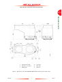
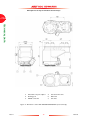
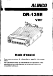
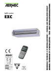
1.
TAV5 vent valve
4.
Main inlet
2.
8 slots 8.4 mm wide
5.
EXDC controller
3.
Side inlet
6.
Backing port
Figure 1 – Dimensions of the EXT 200/200H Split Flow Pump system (units in mm)
Mar 07
7
Issue F
TECHNICAL DATA
The following materials and component types are exposed to the gases pumped: aluminium alloys,
stainless steels, fluoroelastomer and nitrile o-rings, hydrocarbon lubricant, felt, rare earth magnets,
silicon nitride, phenolic resin and carbon-fibre reinforced epoxy resin
EXT Split Flow Compound Turbomolecular Pumps
PAGE
8
TECHNICAL DATA
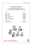
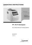
1.
8 slots 8.4 mm wide
4.
TAV5 vent valve
2.
EXDC controller
5.
Main inlet
3.
Backing port
6.
Side inlet
Figure 2 – Dimensions of the EXT 200/200H GCMS Split Flow Pump system (units in mm)
Issue F
8
Mar 07
EXT Split Flow Compound Turbomolecular Pumps
PAGE
9
TECHNICAL DATA
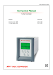
1.
8 slots 8.4 mm wide
4.
Vent port
2.
Controller connection
5.
Main inlet
3.
Backing port
6.
Side inlet
Figure 3 – Dimensions of the EXT 200/200H ICPMS Split Flow Pump system (units in mm)
Mar 07
9
Issue F
EXT Split Flow Compound Turbomolecular Pumps
PAGE
10
TECHNICAL DATA
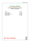
1.
Extended vent-port adaptor
4.
8 slots 8.4 mm wide
2.
Backing port
5.
Main inlet
3.
EXDC controller
6.
Side inlet
Figure 4 – Dimensions of the EXT 200/200H GCMS/LCMS (reversed body)
Issue F
10
Mar 07
EXT Split Flow Compound Turbomolecular Pumps
3
INSTALLATION
3.1
Unpack and inspect
PAGE
11
WARNING
Take care when you unpack the pump to avoid excessive shocks which could damage the bearings and
reduce the life of the pump. The pump is supplied with the inlet and outlet sealed to prevent entry of
dust and vapour. Do not remove these seals until you are ready to install the pump on your vacuum
system.
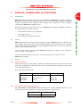
Open the top of the packaging by disengaging the cardboard tabs and then opening the lid. Remove the
top piece of locating foam and any ancillaries included within the box. You should now be able to remove
the pump from the packaging by lifting the pump vertically from the packaging. If the pump is damaged,
notify your supplier and the carrier in writing within three days; state the Item Number of the pump
together with your order number and your supplier’s invoice number. Retain all packing materials for
inspection. Do not use the pump if it is damaged.
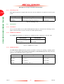
Check that your package contains the items listed in Table 5. If any of these items is missing, notify your
supplier in writing within three days.
If the pump is not to be used immediately, store the pump in suitable conditions as described in
Section 6.1.
It is advised to retain all packing materials for use should you return the pump for service.
Mar 07
11
Issue F
INSTALLATION
The pump weighs approximately 9 kg (20 lbs). Appropriate care should be taken when
lifting and moving the pump to avoid injury.
EXT Split Flow Compound Turbomolecular Pumps
3.2
Typical installation
PAGE
12
CAUTION
Local legislation concerning the impact of the pump on the environment must be followed when
installing the pump.
INSTALLATION
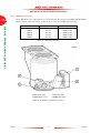
A schematic of a typical vacuum system using a Turbomolecular pump is shown in Figure 5.
1.
2.
3.
4.
5.
6.
7.
8.
9.
10.
11.
12.
13.
Vacuum system
High vacuum gauge
Alternative position for vent valve
TMP
Backing valve
Vacuum gauge
Foreline trap
Rotary backing pump
Mist filter
Cooling fan
EXDC controller
Vent valve
Control system
Figure 5 – A typical vacuum system using a Turbomolecular pump
The accessories available for these EXT Split Flow Pumps are detailed in Section 7.4.
Issue F
12
Mar 07
EXT Split Flow Compound Turbomolecular Pumps
3.3
Connection to the vacuum system
PAGE
13
WARNING
Once the pump is removed from the bottom packaging, there is a danger of toppling.
Install the pump in the vacuum system before you connect the controller to the power
supply. This will ensure that the pump cannot operate and injure people during
installation.
WARNING
The impeller blades on a Split Flow Pump are very sharp. Care should be taken when
handling the pump not to dislodge or damage the protective inlet screens.
WARNING
Under no circumstances must a part of the human body be exposed to a vacuum.
Carefully remove the pump from packaging media and connect to vacuum system.
Qty
*
Description
1
EXT Split Flow Pump
2
Inlet-screen (fitted)
2
Inlet seal (trapped o-rings)
1
Inlet-strainer (Hi variants only, fitted in the interstage-port)
1
EXDC160 Controller (fitted)*
1
NW10-1/8 inch BSP male extended vent port adaptor*
1
NW10 Centering ring*
1
NW10 Clamping ring*
1
NW25 Centering ring*
1
NW25 Clamping ring*
Only supplied with system variants.
Table 5 - List of items supplied
3.3.1
Mechanical fixing
WARNING
Ensure all Split Flow Pumps are securely fixed to the vacuum system via their inlet flange
using all available mounting points. If a pump were to seize when not securely mounted,
the stored energy of the rotor could cause rapid movement of the pump, which may
cause damage to equipment and/or injury to personnel.
For variants listed under the Declaration of Incorporation refer to your own guide lines for mechanical
fixing.
Mar 07
13
Issue F
INSTALLATION
WARNING
EXT Split Flow Compound Turbomolecular Pumps
3.3.2
Inlet-screens (supplied fitted)
PAGE
14
WARNING
Removal of inlet-screens will expose the risk of injury from sharp edges.
INSTALLATION
Do not remove the inlet-screens unless you can be sure that there is no danger that debris can fall into
the pump. If the screens are removed, the pumping speed through each inlet will increase by
approximately 10%.
To remove an inlet-screen carefully extract it from the inlet-flange using a bent wire hook. To replace a
screen which has been removed, install it as shown in Figure 6, with the BOC Edwards logo uppermost.
Ensure that the dimples on the rim of the screen engage in the groove in the pump flange. If necessary,
gently bend the tabs of the screen outwards to ensure a tight fit.
1. Inlet-flange
2. Inlet-screen
Figure 6 – Correct installation of inlet screen
3.3.3
Inlet connection and orientation
CAUTION
Do not invert the pump.
The pump can be mounted in any attitude range shown in Figure 7, from vertical and upright through to
horizontal (±2o), although it is most commonly mounted vertically. If you mount the pump horizontally,
the backing port should point vertically downwards (±20o) to reduce the risk of contamination from the
backing pump oil.
Make sure that the pump’s main inlet and side inlet and all components fitted to the pump-inlets are clean
and dust-free. If the pump-inlets are not kept clean, the pump-down time may be increased.
The inlet-connections of the EXT Split Flow Pump are ISO flanges.
Issue F
14
Mar 07
EXT Split Flow Compound Turbomolecular Pumps
Use the BOC Edwards trapped o-ring supplied with the pump and use a minimum of four fixing bolts to
connect the inlet-flange of the pump to the vacuum system. M8 bolts should be tightened to a torque of
5-6Nm.
PAGE
15
INSTALLATION
Figure 7 – Mounting attitude range of an EXT Split Flow Pump
3.3.4
Backing connection
WARNING
The customer must ensure safe ducting of the backing line if oil mist or hazardous
substances are present.
WARNING
Split Flow Pumps must not be operated, or vented from a positive pressure gas supply,
with a restricted/blocked backing line.
Use suitable vacuum tubing and connectors to connect the NW25 flange of the backingport to your backing-pump. If necessary, use flexible pipe or bellows to reduce the
transmission of vibration from the backing-pump to the Split Flow Pump.
Use suitable vacuum tubing and connectors to connect the NW flange of the backing-port to your
backing-pump. If necessary, use flexible pipe or bellows to reduce the transmission of vibration from the
backing-pump to the EXT Split Flow Pump.
Mar 07
15
Issue F
EXT Split Flow Compound Turbomolecular Pumps
We recommend that you use a BOC Edwards RV Backing-Pump. The minimum size of the backing- pump
required is given in Table 4. You may have to use a larger backing-pump if you run the pump at a high
inlet pressure. The EXT70/200H and EXT200/200H Split Flow Pumps are also suitable for use with
diaphragm backing-pumps although the effect of higher backing pressure on the pump’s performance and
cooling requirements should be noted (see Table 1 and Section 3.6).
PAGE
16
INSTALLATION
CAUTION
Do not use the EXT Split Flow Pump with a backing pressure below 5 x 10⁻⁴ mbar (5 x 10⁻² Pa). Lower
backing pressures will increase the evaporation rate of the lubricating oil and so will reduce the life of
the bearings.
3.3.5
Interstage connection (Hi pump variants only)
Use suitable vacuum tube and connectors to connect the interstage-port to your vacuum system or to
the outlet flange of another turbo molecular pump. Leave the inlet-strainer in the interstage- port, unless
you are sure that debris cannot be drawn into the interstage-port.
3.4
Vent options, vent valve connection and control
To maintain the cleanliness of your vacuum system, we recommend that, whenever you switch the pump
off, you vent the pump (or vacuum system) when the speed of the EXT Split Flow Pump is between full
rotational speed and 50% of full rotational speed. At and above 50% of full rotational speed, the rotor
spins fast enough to suppress any backstreaming of hydrocarbon oil from your backing pump. Venting
may be accomplished by one of the following methods.
•
Use a TAV5 or TAV6 solenoid vent-valve accessory (see Section 7) in place of the manual ventvalve.
•
Use a TAV5 or TAV6 solenoid vent-valve connected to a convenient flange on your vacuum system.
•
Use an alternative valve, with an appropriate restriction, connected to your vacuum system. For
further details contact BOC Edwards.
However, if you manually vent the pump when it is at full rotational speed and the rate of pressure rise
is too high, the pump life may be reduced. When using the manual vent valve supplied, we recommend
that you either limit the vent or only open the vent-valve after the EXT Split Flow Pump speed has fallen
to 50% of full rotational speed.
Do not vent from the backing line, this may lead to contamination. If you vent into your vacuum system,
select a point upstream of the pump, to prevent oil backstreaming from the backing line.
If you use the TAV5 or TAV6 vent-valve you can control it using an EXC Controller, or by other
methods. Table 6 gives an indication of the appropriate orifice size to be fitted to the vent valve for given
vacuum system volumes in order that the vent rate is kept within the limits given in Section 2.3.
Vacuum system volume (1)
Orifice diameter (mm)
< 20
< 1.0
< 10
< 0.7
<5
< 0.5
<2
< 0.35
Table 6 - Vent-restrictor orifice diameter (with atmospheric pressure at the inlet of the vent-valve)
Issue F
16
Mar 07
EXT Split Flow Compound Turbomolecular Pumps
3.5
Electrical installation
PAGE
17
WARNING
The customer must ensure that any electrical circuits are protected from dripping water
caused by condensation on cold surfaces.
It is the responsibility of the customer to ensure that the power supply used is correctly
rated/protected.
WARNING
This product requires a separate power supply (not included). The power supply should
be adequately protected against a hazardous live condition (e.g. in case of a short circuit).
WARNING
The customer must ensure appropriate routing of cables and pipework to avoid slip/trip
hazards.
WARNING
Do not remove the EXDC Controller/EXC Controller cable from the pump until the
pump is completely at rest. To do so could expose personnel to hazardous voltage and
potentially damage the EXDC/EXC Controller.
The EXT Split Flow Pump should be electrically bonded to earth using the connection provided. Refer
to the instruction manual supplied with the controller to complete the electrical installation.
3.5.1
EXDC Controllers
WARNING
The customer must provide an emergency stop circuit to turn off power to the EXDC
controller.
An EXDC Controller requires connection to a suitably rated power supply. The EXDC Controller is
designed to allow a pumping system to operate in a fully automatic system.
3.5.2
EXC Controllers
The EXC Controller provides the electrical supply to the Split Flow Pump through the pump-tocontroller cable. Connect and lock the bayonet connectors at the ends of the cable to the mating
connectors on the pump and the EXC Controller (if applicable). If the cable is disconnected at the pump,
the EXC Controller output is switched off, making the cable safe. However, if the cable is disconnected
from the EXC Controller it should be noted that the other end of the cable is still connected to the
pump. Refer to the appropriate warning in Section 3.5 regarding exposure to hazardous voltages whilst
the pump is still rotating.
The EXC Controller is designed to allow a pumping system to be configured in a variety of ways, from a
basic manually-operated system to a fully automatic system with remote control.
Mar 07
17
Issue F
INSTALLATION
WARNING
EXT Split Flow Compound Turbomolecular Pumps
PAGE
18
3.6
Cooling
3.6.1
Introduction
CAUTION
INSTALLATION
You must cool the pump by forced-air or water cooling to prevent damage to the bearing.
You must use water-cooling in addition to forced air cooling in any of the following operating conditions:
Backing pressure > 10 mbar.
Backing pressure > 8 mbar (800 Pa) and interstage flow > 30 sccm (0.5 mbar.ls-1, 50 Pa.ls-1).
Backing pressure > 5 mbar (500 Pa) and interstage flow > 80 sccm (1.3 mbar.ls-1, 130 Pa.ls-1).
Ambient temperature > 35 oC.
In all other operating conditions, you can use forced-air cooling only. If you use forced-air to cool the
pump, you must ensure that there is an adequate supply of cooling-air to the pump.
During operation, if the temperature of any surface of the pump is higher than 45 oC, the pump is too
hot and you must increase the cooling.
3.6.2
Forced-air cooling
An air-cooler accessory is available for the EXT Split Flow Pumps (refer to Section 7). Fit the air-cooler
as described in the instruction manual supplied with it. If you wish to use an alternative fan for air-cooling,
ensure that the flow rate is above 70 m3h-1 (40 cfm).
3.6.3
Water-cooling
A water-cooling block accessory is available for the EXT Split Flow Pumps (refer to Section 7). Fit the
water cooling block as described in the instruction manual supplied with it. The cooling-water supply
must comply with the specification given in Section 2.4. Pipes in the water-cooling circuit may become
blocked if the cooling-water contains too much calcium carbonate or if it contains particulates which are
too large. Corrosion of the water-cooling circuit may occur if there is too little calcium carbonate and
oxygen in the water. Good quality drinking water is usually suitable for water-cooling. If in doubt, you
must check the quality of your cooling-water supply and, if necessary, provide treatment and filtration.
Connect the cooling-water supply to the water-cooler on the pump as described below. Either of the
two riffled connectors on the water-cooler can be used for the water supply or return connections.
1.
Push reinforced hose (approximately 6mm internal diameter) over the ends of the riffled hose
connectors on the water-cooler on the pump.
2.
Attach the hose with strong hose clips and make sure that they are tightened securely.
You must turn off the cooling-water supply when you switch off the pump to prevent condensation of
vapours inside the pump. The EXC Controller (EXC120 and EXC300) can operate a solenoid-valve for
this purpose.
If you want to remove the pump for maintenance, and you do not want to break the cooling-water circuit,
unscrew the M4 cap-head fixing-screws and remove the water-cooler from the pump. Make sure that
there is a layer of thermal contact grease on the water-cooler before you refit it to the pump.
Issue F
18
Mar 07
EXT Split Flow Compound Turbomolecular Pumps
4
OPERATION
PAGE
19
WARNING
WARNING
Do not move the pump whilst it is running. The gyroscopic forces generated by this
movement can cause excessive use of the back-up bearing and may result in catastrophic
failure of the pump.
WARNING
When power is restored following a power cut, the pump will re-start automatically. The
pump must remain connected to the vacuum system to prevent risk of injury.
WARNING
After power to the pump has been switched off, either through emergency or as a
requirement, the rotor will continue to spin at very high speeds. Until the rotor has
stopped it possesses considerable mechanical energy.
4.1
Start-up
Use the procedure below to start up a basic, manually-controlled pumping system with a manual ventvalve and an EXDC version controller. Refer to the EXDC Instruction Manual.
1.
Ensure the manual vent-valve is closed (turn clockwise to close it).
2.
Turn on the cooling-water supply (if water-cooling is used) and/or switch on the power to the air
cooler.
3.
Start the backing-pump.
4.
When the vacuum system pressure is approximately 10 mbar or less, switch on the power supply
to start the EXT Split Flow Pump.
5.
The pump will then accelerate to full operating speed. Once nominal operating speed is reached,
the normal speed LED on the EXDC Controller will illuminate.
Note: Refer to the controller manual if using the EXC Controller.
Mar 07
19
Issue F
OPERATION
Do not operate the EXT Split Flow Pump unless it is connected to your vacuum system.
If you do, the pump rotor can cause injury. The pump rotor rotates at very high speeds
and the rotating blades might not be visible.
EXT Split Flow Compound Turbomolecular Pumps
4.2
Shut-down
PAGE
20
WARNING
OPERATION
Do not remove the EXDC Controller/EXC Controller cable from the pump until the
pump is completely at rest. To do so could expose personnel to hazardous voltage and
potentially damage the EXDC/EXC Controller.
Note: In an emergency only, open the vent-valve quickly to decelerate the pump rotor in the shortest possible
time.
Use the procedure below to shut down a basic, manually-controlled pumping system with a manual ventvalve and an EXDC Controller. Refer to the EXC Controller Instruction Manual when using an EXC
Controller.
4.3
1.
Close the valve in the backing-line connecting the EXT Split Flow pump to the backing-pump.
2.
Switch off the backing-pump.
3.
Switch off the power supply to the EXT Split Flow Pump.
4.
When the EXT Split Flow Pump rotational speed has fallen to 50% of full rotational speed, turn the
manual vent-valve anti-clockwise to open it. Ensure that the rate of pressure rise does not exceed
the allowed rate of pressure rise, otherwise you can damage the pump: refer to Section 3.4.
5.
If water-cooling is in use, turn off the cooling-water supply and/or turn off the power to the air
cooler.
Safety interlocks and control system
The pump protection and safety interlock features are listed below. Refer to the instruction manual
supplied with the controller for a full description of these features.
4.3.1
EXDC Controllers
•
4.3.2
The EXDC Controller monitors the temperature of the EXT Split Flow Pump and the electrical
power consumption of the pump. If the EXDC Controller detects excessive power consumption
or temperature, the rotational speed of the pump motor is reduced until the power and
temperature return to normal.
EXC Controllers
•
The EXC Controller monitors the temperature of the EXT Split Flow Pump and the electrical
power consumption of the pump. If the EXC Controller detects excessive power consumption or
temperature, the rotational speed of the pump motor is reduced until the power and temperature
return to normal.
•
If the rotational speed is reduced to 50% of nominal speed, then power is removed (or after a user
defined time delay) and the FAIL LED on the EXC Controller lights.
•
If pump rotational overspeed is detected by the EXC Controller, the pump is stopped immediately
and the FAIL LED on the EXC Controller lights.
If the FAIL LED lights, switch off the backing-pump immediately and vent the EXT Split Flow Pump. Once
the EXT Split Flow Pump has stopped, rectify the cause of the failure (refer to Section 5.5), press the
EXC Controller Start/Stop button to reset the Fail condition, and restart the EXT Split Flow Pump. If the
pump is hot, allow sufficient time for it to cool before you restart it.
Note: Any references to LED’s and buttons do not apply to OEM versions of the EXC Controller i.e. EXC100L
or EXC100.
Issue F
20
Mar 07
EXT Split Flow Compound Turbomolecular Pumps
5
MAINTENANCE
PAGE
21
WARNING
WARNING
Allow the pump-rotor to stop, then disconnect the controller before you remove the
pump from your vacuum system for maintenance or fault-finding procedures.
WARNING
Do not remove the EXDC Controller/EXC Controller cable from the pump until the
pump is completely at rest. To do so could expose personnel to hazardous voltage and
potentially damage the EXDC/EXC Controller.
5.1
Introduction
The maintenance operations for the EXT Split Flow Pumps are described in the following sections. The
ISX Inlet-Screen, the WCX Water-Cooler, the inlet-strainer and inlet-flange seals are available as spares
(refer to Section 7). Fit the ISX Inlet-Screen as described in Section 3.3.2. Fit the WCX Water-Cooler
as described in Section 3.6.3.
5.2
Bearing maintenance
When supplied, the pump contains sufficient lubricant to supply the bearings for life. No routine
maintenance is therefore required between bearing replacements. The bearings are not user- serviceable.
The bearings will need to be replaced when they reach the end of their service life. This is typically more
than 20,000 hours, but may be less; this depends on the type of pumping duty on which the pump is used.
When the bearings need replacement, we recommend that you exchange your pump for a factory
reconditioned replacement. Alternatively, you can send your pump to a BOC Edwards Service Centre
to have the bearings replaced.
When you return EXT Split Flow Pumps to BOC Edwards Service Centres please use the procedure
included at the end of this manual. However, the instruction to drain all fluids does not apply to the
lubricant in the EXT Split Flow Pump oil-reservoirs.
5.3
Rotor life
The fatigue life of the EXT Split Flow Pump rotors is typically 40 000 to 50 000 cycles of acceleration
from rest to full speed and then back to rest. As a precautionary measure, BOC Edwards recommends
that pumps are returned for a major service (rotor replacement) after 20 000 cycles or ten years,
whichever occurs first.
Mar 07
21
Issue F
MAINTENANCE
The EXT Split Flow Pumps are not to be serviced by the customer. Pumps requiring
servicing should be returned to BOC Edwards or serviced by a qualified BOC Edwards
engineer.
EXT Split Flow Compound Turbomolecular Pumps
5.4
Cleaning the pump
PAGE
22
WARNING
MAINTENANCE
Clean the external surfaces of the EXT Split Flow pumps in a well-ventilated location.
When you use cleaning solutions and solvents to clean the pump, observe all precautions
specified by the manufacturer. Avoid inhalation of any particulates which may be present
in the pump.
CAUTION
Do not attempt to clean any parts of the EXT Split Flow pumps other than the external surfaces.
Organic solvents may damage internal pump components. Do not use abrasive materials to clean any
part of the pump.
If the inside of the EXT Split Flow pumps is contaminated, it may not be possible to achieve the specified
ultimate vacuum, or pump-down time may increase. In these circumstances the pump must be returned
to a BOC Edwards Service Centre, where the pump will be dismantled and cleaned. Use the procedure
given in the forms at the end of this manual to return the pump.
Use a cleaning solution which is suitable for the contaminants in the pump. You can use any organic
solvent to clean the EXT Split Flow Pump, but we recommend that you use non-CFC solvents, such as
isopropanol or ethanol.
For environmental reasons, keep wastage of cleaning solutions and solvents to a minimum.
5.5
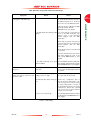
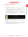
Fault finding
Refer to Table 7 for the possible causes of faults and for the recommended actions to rectify faults.
Table 7 is applicable to a basic, manually controlled pumping system with an EXC Controller configured
for local (manual) operation.
Note that if you use an EXDC Pump Drive Module to control the EXT Split Flow Pump, or if you use an
EXC Controller configured for remote operation to control the EXT Split Flow Pump, some of the
checks and actions in Table 7 may not apply to your system. Refer to the fault finding section of the
instruction manual supplied with your EXDC Pump Drive Module or EXC Controller for further fault
finding information.
Issue F
22
Mar 07
EXT Split Flow Compound Turbomolecular Pumps
Symptom
Check
The impeller does not rotate. After Is the EXC Controller power LED lit?
pressing start - Fail LED not lit.
Action
If all of the above are OK then the EXC
Controller is faulty. Consult
BOC Edwards or your supplier.
Is the EXC Controller Start/Stop LED If so, check that the correct links are
flashing?
made on the EXC Controller logic
interface (refer to the instruction
manual supplied with the EXC
Controller).
Check that any system interlocks are
correctly made (refer to the instruction
manual supplied with the EXC
Controller).
Check that the pump-to-controller lead
is connected.
If you have made all of the above checks
and cannot identify the cause of the
fault, consult BOC Edwards or your
supplier.
Is the EXC Controller first speed If not, the EXC Controller is faulty. If lit,
indication LED lit?
then the EXT Split Flow Pump is faulty.
Consult BOC Edwards or your supplier.
The EXC Controller trips into Fail - at Are the system interlocks correctly Ensure that the system interlocks do
any speed.
connected?
not open after the EXT Split Flow Pump
has started.
The EXC Controller trips into Fail Is the inlet pressure too high? Is the If so, reduce the pumping load, or check
during the ramp-up and before 50% backing pressure too high?
for a gross leak into the system.
speed is reached.
Is the EXT Split Flow Pump running too Increase the cooling-water flow or
hot?
decrease the water temperature or do
both. You may need to add air-cooling
to water-cooling. (Refer to Section 3
for maximum inlet pressure and cooling
requirements). Check that external
heat sources (such as system bakeout
heaters) are not excessive.
Does the rotor rotate freely?
If not, the EXT Split Flow Pump bearings
are damaged. Consult BOC Edwards or
your supplier.
Table 7 - Fault finding
Mar 07
23
Issue F
PAGE
23
MAINTENANCE
If not, check that the electrical supply is
on, check that the switch at the rear of
the EXC Controller is on, check the
fuse in the rear of the EXC Controller.
EXT Split Flow Compound Turbomolecular Pumps
Symptom
PAGE
24
MAINTENANCE
The EXC Controller trips into Fail
after 50% speed has been reached the first two speed LEDs are lit.
Check
Action
Is the timer set incorrectly?
Increase the timer setting (refer to the
instruction manual supplied with the
EXC Controller). If the EXC
Controller still trips into Fail consult
BOC Edwards or your supplier.
Is the pressure too high?
If so, reduce the pumping load or check
for a gross leak into the system.
If the high gas load is temporary,
configure the EXC Controller to delay
the Fail trip on 50% speed and set an
appropriate delay time (refer to the
instruction manual supplied with the
EXC Controller).
Is the EXT Split Flow Pump running too Increase the cooling-water flow or
hot?
decrease the water temperature or do
both. You may need to add air-cooling
to water-cooling.
The EXC Controller trips into Fail
after 50% speed has been reached the first two speed LEDs are lit
(continued).
Does the EXT Split Flow Pump rotor
rotate freely?
The EXC Controller trips into Fail - all
the speed LEDs are lit.
System operating pressure cannot be
reached.
If not, the EXT Split Flow Pump
bearings are damaged. Consult
BOC Edwards or your supplier.
Consult BOC Edwards or your
supplier.
Are any of the vacuum gauges
contaminated?
If so, clean or replace them.
Is the pumping speed insufficient (due
to poor conductance between the
pump and the gauge or too large a
chamber)?
Increase the conductance or reduce
the volume.
Is the interstage inlet pressure > 0.2
mbar (20 Pa)?
If the interstage inlet pressure is too
high, inlet pressure at the
turbomolecular inlet is reduced; ensure
that the interstage inlet pressure is <
0.2 mbar 20 Pa).
Is the backing pressure < 12 mbar
(1200 Pa)?
Check for backing line leaks. If the
backing pressure is too high, you may
need a larger backing pump.
Is the high-vacuum area of the system
contaminated?
If so, clean the high-vacuum system.
Check the rest of your system for leaks If found, clean the contaminated areas
and contamination.
and repair the leaks.
Table 7 - Fault finding (Continued)
Issue F
24
Mar 07
EXT Split Flow Compound Turbomolecular Pumps
Symptom
Check
The EXT Split Flow Pump is very noisy Is the pump rotational speed the same
or there is excessive vibration or both. as the resonant frequency of the
attached system?
If so, change the natural frequency of
your system.
Is the vibration being transmitted from
the rotary pump?
If so, fit flexible bellows or a vibration
isolator in the backing line.
Is the noise irregular and getting
progressively worse?
If so, a bearing is defective. Consult
BOC Edwards or your supplier.
Is the EXT Split Flow Pump making a
constant high-pitched noise?
If so, the rotor is out of balance.
Consult BOC Edwards or your
supplier.
-
Consult BOC Edwards or your
supplier.
Table 7 - Fault finding (Continued)
Mar 07
25
Issue F
PAGE
25
MAINTENANCE
None of the above.
Action
EXT Split Flow Compound Turbomolecular Pumps
PAGE
26
MAINTENANCE
This page intentionally blank.
Issue F
26
Mar 07
EXT Split Flow Compound Turbomolecular Pumps
6
STORAGE AND DISPOSAL
6.1
Storage
PAGE
27
Use the following procedure to store the pump.
Place protective covers over the main inlet, side inlet, outlet, interstage (Hi variants only) and vent
ports.
2.
Place the pump in its packing materials. For fastest pump-down when the pump is put back into
service, seal the pump inside a plastic bag together with a suitable desiccant.
3.
Store the pump in cool, dry conditions until required for use. When required, prepare and install
the pump as described in Section 3.
4.
Keep the pump upright at all times to prevent the drainage of oil from the bearing reservoir.
5.
Avoid long-term storage if possible. When long-term storage is necessary, the pump should be set
up and run for at least eight hours every six months.
Disposal
WARNING
In the unlikely event of a failure of the pump rotor, dust can be generated from the carbon
fibre reinforced components.
In this event, use appropriate Personal Protective Equipment when handling and disposing
of the pump, and ensure that all pump inlets and outlets are capped off before disposal.
Dispose of the EXT Split Flow Pump and any components and accessories safely in accordance with all
local and national safety and environmental requirements.
Particular care must be taken with any components which have been contaminated with dangerous
process substances.
Take appropriate action to avoid inhalation of any particulates which may be present in the pump. Do
not incinerate the pump. The pump contains phenolic and fluorosilicone materials which can decompose
to very dangerous substances when heated to high temperatures.
Mar 07
27
Issue F
STORAGE AND DISPOSAL
6.2
1.
EXT Split Flow Compound Turbomolecular Pumps
PAGE
28
STORAGE AND DISPOSAL
This page intentionally blank.
Issue F
28
Mar 07
EXT Split Flow Compound Turbomolecular Pumps
7
SERVICE, SPARES AND ACCESSORIES
7.1
Introduction
PAGE
29
Order spare parts and accessories from your nearest BOC Edwards company or distributor. When you
order, please state for each part required:
7.2
•
Model and item number of your equipment.
•
Serial number (if any).
•
Item number and description of the part.
Service
BOC Edwards products are supported by a worldwide network of BOC Edwards Service Centres. Each
Service Centre offers a wide range of options including: equipment decontamination; service exchange;
repair; rebuild and testing to factory specifications. Equipment which has been serviced, repaired or
rebuilt is returned with a full warranty.
Your local Service Centre can also provide BOC Edwards engineers to support on-site maintenance,
service or repair of your equipment.
For more information about service options, contact your nearest Service Centre or other
BOC Edwards company.
7.3
Spares
7.3.1
ISX Inlet-Screens
Inlet-screens are fitted to your pump as supplied to prevent damage from the entry of debris into the
pump. The Item Numbers of replacement inlet-screens are given below. Select the inlet-screen according
to the pump inlet-flange size.
Note: Kits contain 10 screens each.
Flange size
Inlet-screen
Item Number
DN100ISO-K
ISX100
B736-00-122
DN100ISO-K
ISX100 (coarse)
B756-40-813
DN63ISO-K
ISX63
B722-00-116
Table 8 - ISX Inlet-screens
7.3.2
Inlet-strainer (interstage pumps only)
The EXT70/200Hi and EXT200/200Hi Split Flow Pumps are supplied with inlet-strainers for the
interstage- port. The Item Number of a replacement inlet-strainer is given below.
Flange size
NW25ISO-K
Item Number
A223-05-067
Table 9 - Inlet-strainer (interstage pumps only)
Mar 07
29
Issue F
SERVICE, SPARES AND ACCESSORIES
BOC Edwards products, spares and accessories are available from BOC Edwards companies in Belgium,
Brazil, Canada, France, Germany, Hong Kong, Italy, Japan, Korea, United Kingdom, USA and a worldwide
network of distributors. The majority of these employ service engineers who have undergone
comprehensive BOC Edwards training courses.
EXT Split Flow Compound Turbomolecular Pumps
7.3.3
Inlet-flange seals
EXT Split Flow Pumps are supplied with inlet seals. The Item Numbers of replacement seals are given
below.
PAGE
30
SERVICE, SPARES AND ACCESSORIES
Flange size
Inlet-flange seal
Item Number
DN100ISO-K
ISO100 trapped o-ring, fluoroelastomer
B271-58-171
DN63ISO-K
ISO63 trapped o-ring, fluoroelastomer
B271-58-170
Table 10 - Inlet-flange seals
7.4
Accessories
7.4.1
Installation
The accessories available for use with the EXT Split Flow Pumps are described in the following sections.
Figure 2 shows how the accessories are fitted to an EXT Split Flow Pump.
7.4.2
EXDC Drive Modules
Fit an EXDC Drive Module as an alternative to an EXC Controller and pump-to-controller cable.
Drive Module
Item Number
EXDC160 24 V 45 deg
D396-46-600*
EXDC160 80 V
D396-41-000
* Pump system originally supplied with D396-46-510 (unpackaged)
Table 11 - EXDC Drive modules
7.4.3
EXC Controllers
The BOC Edwards EXC Controllers provide the facilities necessary for operating a pumping system
based on an EXT70/200H, EXT70/200Hi, EXT200/200H or EXT200/200Hi Split Flow Pump. The Item
Numbers of the EXC Controllers are given below.
Controller
Voltage
Item Number
EXC100E
90 - 264 V a.c.
D396-20-000
EXC100L
90 - 264 V a.c.
D396-22-000
EXC120
90 - 264 V a.c.
D396-16-000
EXC300
90 - 132/180 - 264 V a.c.
D396-14-000
Table 12 - EXC Controllers
Issue F
30
Mar 07
EXT Split Flow Compound Turbomolecular Pumps
7.4.4
Pump-to-controller cables
You must fit a pump-to-controller cable between an EXC Controller and the EXT Split Flow Pump. A
cable is not supplied with the EXT Split Flow Pump or the EXC Controller (except EXC100L). The
following cables are available:
Length
Item Number
Pump-to-controller
1m
D396-18-010
Pump-to-controller
3m
D396-18-030
Pump-to-controller
5m
D396-18-050
Table 13 - Pump-to-controller cable
7.4.5
EXT Water cooling block assembly
A water-cooler can be fitted to the EXT Split Flow Pump. However please refer to Section 2.4 to check
the stability of the cooling-water supply.
Water-cooler
WCX250M
Item Number
B735-01-164
Table 14 - EXT Water cooling block assembly
7.4.6
TAV Vent-valve and vent-port adaptor
Two solenoid-operated vent-valves are available for system venting. The valves are 24 V d.c., normallyopen, and can be driven automatically from the EXC Controller. The solenoid-valve is fitted in place of
the manual-valve, or alternatively can be fitted with an adaptor (supplied with the valve) and be used with
any suitable NW10 flanged port on your vacuum system. The vent-port adaptor allows the vent-port or
the purge-port to be used with any suitable NW10 fitting.
Product
Item Number
TAV5 vent-valve
B580-66-010
TAV6 vent-valve
B580-66-020
NW10-1/8 inch BSP male adaptor
B580-66-011
NW10-1/8 inch BSP male extended
vent port adaptor
B580-66-028
Table 15 - TAV Vent-valve and vent-port adaptor
7.4.7
ACX Air-Cooler
An ACX air-cooler can be fitted to the EXT Split Flow Pump. However, please refer to Section 2 to
check the suitability of air-cooling in a particular application.
Air-cooler
ACX250H
Item Number
B580-53-160
Table 16 - ACX Air-cooler
Mar 07
31
Issue F
SERVICE, SPARES AND ACCESSORIES
Cable
PAGE
31
EXT Split Flow Compound Turbomolecular Pumps
7.4.8
VRX Vent-restrictor
Use a VRX fixed orifice vent-restrictor to restrict the flow of vent gas into the EXT Split Flow Pump.
Refer to Section 3.4 for information on the selection of the correct VRX Vent-restrictor.
PAGE
32
SERVICE, SPARES AND ACCESSORIES
Vent-restrictor
Orifice diameter
Item Number
VRX10
VRX20
VRX30
VRX50
VRX70
0.1 mm
0.2 mm
0.3 mm
0.5 mm
0.7 mm
B580-66-021
B580-66-022
B580-66-023
B580-66-024
B580-66-025
Table 17 - VRX Vent-restrictor
1. ACX Cooling fan
3. TAV Vent-valve
2. WCX Water-cooler
4. EXDC Controller
Figure 8 – Installation of optional accessories
Issue F
32
Mar 07
INDEX
A
Mechanical fixing . . . . . . . . . . . . . . . . . . . . . . . . . . 13
Accessories . . . . . . . . . . . . . . . . . . . . . . . . . . . . . 30
ACX air-cooler . . . . . . . . . . . . . . . . . . . . . . . . . . 31
P
B
Pumping media . . . . . . . . . . . . . . . . . . . . . . . . . . . . 3
Pump-to-controller cables . . . . . . . . . . . . . . . . . . 31
Backing connection . . . . . . . . . . . . . . . . . . . . . . . 15
Bearing maintenance . . . . . . . . . . . . . . . . . . . . . . 21
R
Rotor life . . . . . . . . . . . . . . . . . . . . . . . . . . . . . . . 21
C
S
Cautions . . . . . . . . . . . . . . . . . . . . . . . . . . . . . . . . . 1
Cleaning the pump . . . . . . . . . . . . . . . . . . . . . . . . 22
Connection to the vacuum system . . . . . . . . . . . 13
Cooling . . . . . . . . . . . . . . . . . . . . . . . . . . . . . . . . . 18
Safety interlocks and control system . . . . . . . . . . 20
Scope and definitions . . . . . . . . . . . . . . . . . . . . . . . 1
Service . . . . . . . . . . . . . . . . . . . . . . . . . . . . . . . . . 29
Shut-down . . . . . . . . . . . . . . . . . . . . . . . . . . . . . . 20
Spares . . . . . . . . . . . . . . . . . . . . . . . . . . . . . . . . . . 29
D
Disposal . . . . . . . . . . . . . . . . . . . . . . . . . . . . . . . . 27
T
E
TAV vent-valve . . . . . . . . . . . . . . . . . . . . . . . . . . . 31
Typical installation . . . . . . . . . . . . . . . . . . . . . . . . 12
Electrical installation . . . . . . . . . . . . . . . . . . . . . . 17
EXC Controllers . . . . . . . . . . . . . . . . . . . . . . 20, 30
EXC controllers . . . . . . . . . . . . . . . . . . . . . . . . . . 17
EXDC Controllers . . . . . . . . . . . . . . . . . . . . . . . . 20
EXDC controllers . . . . . . . . . . . . . . . . . . . . . . . . 17
EXDC drive modules . . . . . . . . . . . . . . . . . . . . . . 30
EXT water cooling block assembly . . . . . . . . . . . 31
EXT200/200H . . . . . . . . . . . . . . . . . . . . . . . . . . . . 1
EXT200/200Hi . . . . . . . . . . . . . . . . . . . . . . . . . . . . 6
EXT70/200H . . . . . . . . . . . . . . . . . . . . . . . . . . . . . 1
U
Unpack and inspect . . . . . . . . . . . . . . . . . . . . . . . 11
V
VRX vent-restrictor . . . . . . . . . . . . . . . . . . . . . . . 32
W
Warnings . . . . . . . . . . . . . . . . . . . . . . . . . . . . . . . . 1
Water-cooling . . . . . . . . . . . . . . . . . . . . . . . . . . . 18
F
Fault finding . . . . . . . . . . . . . . . . . . . . . . . . . . . . . 22
Forced-air cooling . . . . . . . . . . . . . . . . . . . . . . . . 18
G
General . . . . . . . . . . . . . . . . . . . . . . . . . . . . . . . . . . 3
I
Inlet connection and orientation . . . . . . . . . . . . . 14
Inlet-flange seals . . . . . . . . . . . . . . . . . . . . . . . . . . 30
Inlet-screens . . . . . . . . . . . . . . . . . . . . . . . . . . . . . 14
Inlet-strainer . . . . . . . . . . . . . . . . . . . . . . . . . . . . . 29
Installation . . . . . . . . . . . . . . . . . . . . . . . . . . . . . . 30
Interstage connection . . . . . . . . . . . . . . . . . . . . . 16
INTRODUCTION . . . . . . . . . . . . . . . . . . . . . . . . . 1
Introduction . . . . . . . . . . . . . . . . . . . . . . .18, 21, 29
ISX Inlet-Screens . . . . . . . . . . . . . . . . . . . . . . . . . 29
M
MAINTENANCE . . . . . . . . . . . . . . . . . . . . . . . . . 21
Materials exposed to gases pumped . . . . . . . . . . . 7
Mar 07
33
Issue F
PAGE
33
PAGE
34
This page intentionally blank.
Issue F
34
Mar 07