1
B777-50-880 Issue A Original
Instruction Manual
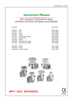
EXT Compound Turbomolecular Pumps:
EXT556H and EXT556HF
Description
Item Number
EXT556H / DN160ISO-K
EXT556H / DN160CF
EXT556H / DN160ISO-K (fine inlet)
EXT556HF / DN160ISO-K
EXT556HF / DN160CF
B777-51-000
B777-52-000
B777-61-000
B777-57-000
B777-58-000
98/37/EC
89/336/EEC
73/023/EEC
BOC EDWARDS
.%,
Declaration
of Conformity
We, BOC Edwards,
Manor Royal,
Crawley,
West Sussex RH10 2LW, UK
declareunder our sole responsibilitythat the product(s):
Pumps:
EXT556HCompoundTurboMolecular
EXTs56H
DNl60ISO-K
EXT556H
DNl6OCF
EXT556HDNl60150.K(fineinlet)
EXT556HF
DNl60150.K
EXT556HF
DN'16OCF
8777-51-000
8777-52-000
8777-61-000
8777-57-000
8777-58-OO0
to which this declaration relates is in conformity with the following standard(s)
or other normative document(s):
E N 1 2 1 0200: 0 3
Safetyof machinery.Basicconcepts,generalprincipalsfor design
principals.
Technical
'1997
EN1012-2:
Compressorsand VacuumPumps- SafetyRequirements- Part 2: Vacuum
Pumps.
E N 6 1 0 1 0 - 1 ; 2 0 0 1 SafetyRequirementsfor ElectricalEquipmentfor Measuremenq
Control and LaboratorvUse.x
EN61326:1998
Elecffical
Equipment
for Measurement,
Control and
(lndustrialLocation,
LaboratoryUse- EMC Requirements.
ClassB Emissions)
*
The pumpscomplywith EN610101:2001when installed
in accordance
with the instruction
manualsuppliedwith the pumps.
followingthe provisionsof:
73l023lEEC Low VoltageDirective.
89/336/EEC ElectromagneticCompatibilityDirective.
98l37lEC
MachinerySafetyDirective.
3t/
t I z'Do 6
B Uazq,e3s
B. D. Brewster,fechnicol Manager,
BurgessHill Producs
l-{ t L-(-
Ddte ond Ploce
9
f
This product hasbeen manufacturedunder a qualitysystemregisteredto lSO9001
W
BOC EDWARDS
EXT556H
CONTENTS
PAGE
djd/0267
Section
Title
1
INTRODUCTION
1
1.1
Scope and definitions
1
2
TECHNICAL DATA
3
2.1
2.2
2.2.1
2.2.2
2.3
2.4
2.5
2.6
General
Pumping media
Pumps without gas purge
Pumps with gas purge
Vent gas specification and vent control data
Purge gas specification
Water cooling
Materials exposed to gases pumped
3
3
4
4
4
5
5
6
3
INSTALLATION
11
3.1
3.2
3.3
3.3.1
3.3.2
3.3.3
3.4
3.5
3.5.1
3.5.2
3.6
3.7
3.7.1
3.7.2
3.7.3
3.8
Unpack and inspect
Typical installation
Connection to the vacuum system
The inlet screen (supplied fitted)
Inlet connection
Backing connection
Vent options, vent valve connection and control
Purge gas connection
Connect the purge gas
Recommended purge gas flow
Electrical installation
Cooling
Introduction
Forced air cooling
Water cooling
Magnetic Fields
11
11
11
13
13
15
15
17
17
17
17
19
19
19
20
20
4
OPERATION
21
4.1
4.2
4.3
4.4
4.5
Start up
Stand-by
Shut-down
Safety interlocks and control system
Bakeout (conflat only)
21
21
21
22
22
5
MAINTENANCE
23
5.1
5.2
5.3
5.4
5.5
Introduction
Bearing maintenance
Rotor life
Clean the pump
Fault finding
23
23
23
23
24
Aug 05
i
Page
i
Issue A
EXT556H
CONTENTS (continued)
PAGE
ii
Section
Title
Page
6
STORAGE AND DISPOSAL
27
6.1
6.2
Storage
Disposal
27
27
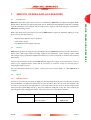
7
SERVICE, SPARES AND ACCESSORIES
29
7.1
7.2
7.3
7.3.1
7.3.2
7.4
7.4.1
7.4.2
7.4.3
7.4.4
7.4.5
7.4.6
7.4.7
7.4.8
7.4.9
7.4.10
7.4.11
7.4.12
Introduction
Service
Spares
ISX inlet-screen
Inlet-flange seals
Accessories
Installation
EXC controller
Pump-to-controller cable
EXDC drive modules
BX bakeout band (conflat only)
FL20K foreline trap
TAV vent-valve and vent-port adaptor
ACX air-cooler
WCX water-cooler
Vibration isolators
PRX purge-restrictor
VRX vent-restrictor
29
29
29
29
30
30
30
30
32
32
32
33
33
33
34
34
34
34
ILLUSTRATIONS
Figure
1
2
3
4
5
6
Issue A
Title
Page
Mounting attitude of the EXT556H pump
9
Typical pumping system
12
Diagram of inlet screen - remove screws 'A' in order to remove
the inlet screen. Do not remove screws 'B'
14
Maximum rate of pressure rise when venting
16
Dimensions and features of EXT556H pumps
18
Installation of EXT556H optional accessories and spares 31
ii
Aug 05
EXT556H
TABLES
PAGE
Table
1
2
3
4
5
6
7
8
9
10
11
12
13
14
15
16
17
18
19
20
21
Title
iii
Page
General information
3
Vent gas and vent control data
4
Purge gas specification
5
Cooling water specification
5
Technical data
6
List of items supplied
11
Vent restrictor orifice diameter (with atmospheric pressure at
the inlet)
15
Fault finding
24
ISX inlet-screen
29
Inlet-flange seals
30
EXC controller
30
Pump-to-controller cable
32
EXDC drive modules
32
BX bakeout band
32
FL20K foreline trap
33
TAV vent-valve and vent-port adaptor
33
ACX air-cooler
33
WCX water-cooler
34
Vibration isolators
34
PRX purge-restrictor
34
VRX vent-restrictor
34
ASSOCIATED PUBLICATIONS
Publication Title
Publication Number
EXC120/120E/300/300M Turbomolecular Pump Controllers
EXC250E/250L Turbomolecular Pump Controllers
EXDC Turbomolecular Pump Drive Modules
Aug 05
iii
D396-14-880
D396-36-880
D396-40-880
Issue A
EXT556H
PAGE
iv
This page intentionally blank.
Issue A
iv
Aug 05
EXT556H
1
INTRODUCTION
1.1
Scope and definitions
PAGE
1
The EXT556H pump is designed for use with a BOC Edwards EXC or EXDC controller. Read this manual and
the instruction manual supplied with your controller before you attempt to install or operate the equipment.
The controller manual contains details of electrical installation.
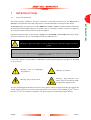
Important safety information in this manual is highlighted as WARNING and CAUTION instructions. Please
obey these instructions. The use of warnings and cautions is defined below.
WARNING
Warnings are given where failure to observe the instruction could result in injury or death to
people.
CAUTION
Cautions are given where failure to observe the instruction could result in damage to the equipment, associated
equipment or process.
In accordance with the recommendations of EN61010, the following warning symbols may appear on the pump
or its accessories:
Warning - refer to accompanying
documentation.
Warning - hot surfaces.
Warning - Large attractive forces
will be experienced when the pump
is subjected to magnetic fields.
Warning - risk of electric shock.
The units used throughout this manual conform to the SI system of units of measurement. Also, throughout this
manual, wherever flow rates are specified, the abbreviation 'sccm' is used to mean standard cm3 min-1: this is a
flow of 1cm3 min-1 at an ambient temperature of 0 °C and a pressure of 1013 mbar (1.013 x 10⁵ Pa).
Aug 05
1
Issue A
INTRODUCTION
This manual provides installation, operation, maintenance and storage instructions for the BOC Edwards
EXT556H compound turbo-molecular pumps. Please read and follow all the instructions in this manual.
EXT556H
PAGE
2
This page intentionally blank.
Issue A
2
Aug 05
EXT556H
2
TECHNICAL DATA
2.1
General
PAGE
3
General items
Reference data
See Table 5
Dimensions and features
See Figure 5
TECHNICAL DATA
Performance
Maximum permitted external magnetic field
EXT556H DN160CF
3 mT horizontal, 5 mT vertical
EXT556H DN160ISO-K
2.5 mT horizontal, 5 mT vertical
EXT556HF ISO and CF variants
50mT in any orientation
Installation category
EN61010 part 1, category 1
Pollution degree
EN61010 part 1, category 2
Equipment type
Fixed equipment, for indoor use only
Operating altitude
up to 3000 m
Ambient temperature
5 °C - 35 °C (air cooled)
5 °C - 40 °C (water cooled)
Relative humidity
10 - 95% non condensing
Table 1 - General information
2.2
Pumping media
WARNING
Vent dangerous gases and gas mixtures safely. Do not expose people to these gases.
WARNING
Do not use EXT556H pumps to pump explosive gas mixtures as the pumps are not suitable for
this purpose.
WARNING
Do not use the EXT556H pump to pump mercury vapour, and do not allow mercury to come
into contact with the pump. If you do, the rotor may corrode and fail.
CAUTION
Do not use an EXT556H pump to pump gases containing more than 20% oxygen unless a bearing purge is
applied as stated in Section 2. If you do the lubricant will be damaged and the pump will fail prematurely.
Note:
Aug 05
Concentrations of gases may be modified by the compression of the pump.
3
Issue A
EXT556H
2.2.1
PAGE
Pumps without gas purge
The pumps are designed to pump the following residual gases normally used in high vacuum systems:
4
TECHNICAL DATA
•
•
•
•
•
•
•
Air
Nitrogen
Krypton
Neon
Hydrogen
Propane
Methane
•
•
•
•
•
•
Carbon dioxide
Carbon monoxide
Helium
Argon
Ethane
Butane
You can use the pumps to pump oxygen and water vapour subject to the following conditions:
• Oxygen
The oxygen concentration must be less than 20% by volume unless a bearing purge is applied as detailed
in Section 2.2.2.
• Water vapour
You must ensure that vapour does not condense inside the pump - refer to Section 3.7.3.
If you wish to pump a gas not previously listed, contact your supplier for advice. If you do not contact your
supplier you may invalidate the warranty on the pump.
The pumps are not suitable for pumping aggressive or corrosive gases.
2.2.2
Pumps with gas purge
When purged with an inert gas the pumps can be used to pump oxygen in concentrations above 20% by volume.
2.3
Vent gas specification and vent control data
Although the pump may be vented to atmosphere, relatively high air humidity may greatly increase the
subsequent pump-down time. To reduce pump-down times you should vent the pump with dry, clean gases.
Vent gas system items
Reference data
Vent gas
Dry air, nitrogen, argon or other inert gases
Maximum dew point at atmospheric pressure
-22 °C
Maximum size of particulate
1 micron
Maximum concentration of oil
0.1 parts per million
Time for rotational speed to reach 50%
>15 seconds
Maximum allowed rate of pressure rise
see Figure 4
Table 2 - Vent gas and vent control data
Issue A
4
Aug 05
EXT556H
2.4
Purge gas specification
Purge gas system items
PAGE
Reference data
5
Dry nitrogen, argon or other inert gases
Maximum dew point at atmospheric pressure
-22 °C
Maximum size of particulates
1 micron
Maximum concentration of oil
0.1 parts per million
Allowable purge gas flow (when required)
20 to 150 sccm (0.33 to 2.48 mbar l s-1, 33 to 248
Pa l s-1)
Recommended purge gas flow
25 sccm (0.42 mbar l s-1, 42 Pa l s-1)
Maximum allowable purge gas supply pressure
2 bar gauge (29 psig, 3 x 10⁵ Pa)
Table 3 - Purge gas specification
2.5
Water cooling
The following water cooling specification corresponds to a typical high quality drinking water specification.
Check with your water supply authority if you are in doubt about the quality of your supply.
Cooling water system items
Reference data
Quality
Mechanically clean and optically with no deposits
or turbidity
pH value
6.0 to 8.0
Maximum calcium carbonate concentration
75 parts per million
Maximum chloride concentration
100 parts per million
Minimum oxygen concentration
4 parts per million
Recommended water cooling flow rate (at 15 °C)
15 l hr-1
Water temperature
See Table 5
Maximum water pressure
5 bar (gauge), 73.5 psig, 6 x 10⁵ Pa
Materials exposed to cooling water
Copper, brass and nickel plating
Table 4 - Cooling water specification
Aug 05
5
Issue A
TECHNICAL DATA
Purge gas
EXT556H
2.6
PAGE
6
Materials exposed to gases pumped
The following materials and component types are exposed to the gases pumped: aluminium alloys, stainless
steels, fluoroelastomer and nitrile 'O' rings, hydrocarbon lubricant, rare earth magnets, silicon nitride, phenolic
resin and carbon fibre epoxy resin.
TECHNICAL DATA
Parameter
EXT556H
Mass EXT556H DN160ISO-K
13.4 kg
Mass EXT556H DN160CF
21.2 kg
Mass EXT556HF DN160ISO-K
19.3 kg
Mass EXT556HF DN160CF
20.5 kg
Main inlet flange
DN160ISO-K/DN160CF
Outlet flange
DN25NW
Vent port
1/8 inch BSPP
Purge port
1/8 inch BSPP
Notes
Inlet pumping speed *
N2
540 l s-1
He
580 l s-1
H2
500 l s-1
Ar
510 l s-1
Inlet compression ratio
**
N2
>1010
Pb < 20 mbar
He
108
Pb < 12 mbar
H2
106
Pb < 7 mbar
Ar
>1010
Pb < 20 mbar
Ultimate
CF
ISO
pressure¹
<10-10 mbar
<2 x 10⁻⁹ mbar
Minimum backing pump
displacement
12 m3 h-1
Recommended backing pump
RV12
Maximum continuous inlet
pressure (light gas pumping) ††
These pressures relate to the
aluminium envelope variant B77751-000. Performance will vary for
other pump variants when air
cooled.
Forced air cooled, 30 °C ambient
1.5 x 10⁻³ mbar
Forced air cooled, 35 °C ambient
1.0 x 10⁻³ mbar
Water cooling at 15 °C
2.0 x 10⁻³ mbar
Table 5 - Technical data
Issue A
6
Aug 05
EXT556H
Parameter
EXT556H
Maximum continuous inlet
pressure (argon pumping) ††
Notes
Forced air cooled, 30 °C ambient
8.0 x 10⁻⁴ mbar
Forced air cooled, 35 °C ambient
5.0 x 10⁻⁴ mbar
Water cooling at 15 °C
1.0 x 10⁻³ mbar
Water cooling while pumping high
concentrations of argon is not
recommended
Maximum continuous backing
pressure (light gas pumping) ††
These pressures relate to the
aluminium envelope variant B77751-000. Performance will vary for
other pump variants when air
cooled.
Forced air cooled, 30 °C ambient
10 mbar
Forced air cooled, 35 °C ambient
6 mbar
Water cooling at 15 °C
7.5 mbar
Maximum continuous backing
pressure (argon pumping) ††
These pressures relate to the
aluminium envelope variant B77751-000. Performance will vary for
other pump variants when air
cooled.
Forced air cooled, 30 °C ambient
2.9 mbar
Forced air cooled, 35 °C ambient
1.8 mbar
Water cooling at 15 °C
2.2 mbar
Water cooling while pumping high
concentrations of argon is not
recommended
Operating attitude
See note at right
Vertical (inlet uppermost) to
Horizontal, not inverted. Range of
rotation of ± 60° about the axis.
Refer to Figure 1.
Nominal rotational speed
50000 rpm
Start time to 90% speed:
EXC250
< 8 minutes
EXC300
< 8 minutes
EXDC160
< 8 minutes
Table 5 - Technical data (continued)
Aug 05
7
Issue A
PAGE
7
TECHNICAL DATA
These pressures relate to the
aluminium envelope variant B77751-000. Performance will vary for
other pump variants when air
cooled.
EXT556H
Parameter
PAGE
8
Cooling
method‡
EXT556H
forced air / water
TECHNICAL DATA
Ambient air temperature for
forced air cooling
0 °C - 35 °C
Minimum cooling water flow rate
(water at 15 °C)
15 l h-1
Water temperature
10 °C - 20 °C
Noise level at 1 metre
<60 dBA
Recommended controllers
EXC250, EXC300, EXDC160
Quiescent power consumption
35 W
*
Notes
Pumping speeds are without inlet screen.
The coarse and fine inlet screen reduces the pumping speed by 11% and 17% respectively.
** Pb = backing pressure
††
Above this pressure the rotational speed of the pump drops below nominal. Heavy gas for example an
atomic mass greater than 28 AMU and light gas for example atomic mass less than or equal to 28 AMU.
‡
If air cooling is required, BOC Edwards recommend the ACX555.
¹
Ultimate pressure is measured 48 hours after bakeout with a 2 stage rotary pump.
Table 5 - Technical data (continued)
Issue A
8
Aug 05
EXT556H
PAGE
9
TECHNICAL DATA
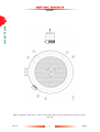
1.
2.
Inlet
Backing port
Figure 1 - Mounting attitude of the EXT556H pump
Aug 05
9
Issue A
EXT556H
PAGE
10
This page intentionally blank.
Issue A
10
Aug 05
EXT556H
3
INSTALLATION
3.1
Unpack and inspect
PAGE
11
WARNING
CAUTION
Do not damage the envelope surface of the HF variant as this may cause corrosion and a reduction in
performance. In this event the pump must be returned to your nearest service centre.
Take care when you unpack the pump to avoid excessive mechanical shocks which could damage the bearings
and reduce the life of the pump. The pump is supplied with the inlet and the outlet sealed to prevent entry of
dust and vapour. Do not remove these seals until you are ready to install the pump on your vacuum system.
Remove all the outer cardboard packaging and check the pump. If the pump is damaged, notify your supplier and
carrier in writing within three days; state the item number of the pump together with your order number and
your supplier's invoice number. Retain all the packing materials for inspection. Do not use the pump if it is
damaged.
Check that your package contains the items listed in Table 6. If any of these items is missing, notify your supplier
in writing within three days.If the pump is not to be used immediately, store the pump in suitable conditions as
described in Section 6.1. It is advised that you retain all packing materials for use should you return the pump
for service.
3.2
Typical installation
A typical pump system with an EXT556H pump is shown in Figure 2.The accessories available for the EXT556H
pump are detailed in Section 7.4. The accessories are shown in Figure 6.
3.3
Connection to the vacuum system
Carefully remove the pump from packaging media and connect to the vacuum system.
WARNING
Install the pump on the vacuum system before you connect the controller to the power supply.
This will ensure that the pump cannot operate and injure people during installation.
Qty
Description
1
EXT556H turbomolecular pump
1
Inlet screen (fitted)
1
Inlet seal (trapped 'O' ring, co-seal or copper compression gasket)
Table 6 - List of items supplied
Aug 05
11
Issue A
INSTALLATION
The EXT556H DN160CF pump variant weighs 21 kg. Observe correct manual handling
techniques when manoeuvring it.
EXT556H
PAGE
12
INSTALLATION
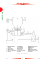
1. Alternative position for
vent-valve
2. Vacuum system
3. High-vacuum gauge
4. Inlet-screen (supplied fitted)
5. EXT pump
6. Backing valve
7. Vacuum gauge
8. Flexible bellows
9. Foreline trap
10. Rotary backing pump
11. Mist filter
12. Cooling water connectors
13. EXC controller
14. Air cooler
15. PRX10 purge restrictor
16. Regulated purge gas supply
17. Vent-valve
Figure 2 - Typical pumping system
Issue A
12
Aug 05
EXT556H
3.3.1
The inlet screen (supplied fitted)
PAGE
WARNING
13
Removal of inlet screen will expose people to the risk of injury from sharp edges.
Removal of the inlet screen could allow debris to fall into the pump, which could cause serious damage to the
pump.
Do not remove the inlet screen unless you can be sure that there is no danger that debris can fall into the pump.
If the inlet screen are removed, the pumping speed through the inlet will increase by 11% for a coarse and 17%
for a fine screen.
To remove the inlet screen, undo the three screws ('A') which hold it down (Figure 3). If you need to replace
the inlet screen, do so by undoing these screws, changing the inlet screen, and replacing the screws. Ensure that
screws are firmly tightened.
CAUTION
Do not remove the three screws which retain the locking plate ('B' in Figure 3). If you do so the pump settings
may change and the pump may cease to operate or have a shortened life.
3.3.2
Inlet connection
WARNING
Ensure that the EXT556H pump is securely fixed to the vacuum system following the instructions
below. If you do not, and the pump seizes, the stored energy of the rotor can cause rapid
movement of the pump, which may cause injury to people and further damage to equipment.
CAUTION
The pump is able to operate up to the horizontal attitude axially. If it is mounted off-vertical, ensure that the
backing port is within 60° of vertical. Refer to Figure 1.
Ensure that the EXT556H pump is securely fixed to the vacuum system following the instructions below.
Make sure that the pump inlet and all components fitted to the pump inlet are clean and dust free. If the pump
inlet is not kept clean the pump down time may be increased. Use the vacuum seal provided with the pump.
If you are using an EXT556H ISO160 pump, connect it to the vacuum system using an ISO160 rotatable flange
with a full complement of bolts. Alternatively use at least 8 claw clamps.
If you are using an EXT556H DN160CF, use a full complement of 20 M8 bolts to attach the pump to your
vacuum system.
Aug 05
13
Issue A
INSTALLATION
CAUTION
EXT556H
PAGE
14
INSTALLATION
Figure 3 - Diagram of inlet screen - remove screws 'A' in order to remove the inlet screen. Do not remove
screws 'B'
Issue A
14
Aug 05
EXT556H
If the inlet flange of the EXT556H is not connected to a rigid, firmly fixed vacuum system, ensure that the base
of the pump is fixed to a firm support. Remove the four feet and secure the pump using eight M8 bolts through
the tapped fixing holes in the base of the pump. These bolts should be in ISO 898-1 class 8.8 or higher, and should
be tightened up to approximately 7Nm torque. If you are using a WCX555 water cooling accessory, mount
through the cooling plate into the tapped holes on the base of the pump.
3.3.3
Backing connection
Use suitable vacuum tubing and connectors to connect the NW flange of the backing port to your backing pump.
If necessary use flexible pipe or bellows to reduce the transmission of vibration from the backing pump to the
EXT556H pump.
We recommend that you use a BOC Edwards RV backing pump. The minimum size of the backing pump
required is given in Table 5. You may have to use a larger backing pump if you run the pump at a high inlet
pressure or high throughput, or if you purge the pump.
CAUTION
If the EXT pump is to be backed by the interstage port of another turbomolecular pump, make sure that the
backing pressure does not fall below 5 x 10⁻⁴ mbar (5 x 10⁻² Pa). Lower backing pressures will increase the
evaporation rate of the lubricant and so will reduce the life of the bearings.
3.4
Vent options, vent valve connection and control
To maintain the cleanliness of your vacuum system we recommend that, whenever you switch the pump off, you
vent the pump or the vacuum system when the speed of the EXT556H pump is between full rotational speed
and 50% of full rotational speed. At and above 50% of full rotational speed the rotor spins fast enough to
suppress any hydrocarbon oil from your backing pump. Venting may be accomplished by one of the following
methods:
• Use a TAV5 or TAV6 solenoid vent valve accessory (see Section 7) in place of the manual vent valve.
• Use a TAV5 or TAV6 solenoid vent valve connected to a convenient flange on your vacuum system
upstream of the turbo pump.
• Use an alternative valve connected to your vacuum system upstream of the turbomolecular pump.
The maximum rate of pressure rise is given in Figure 4.
Vacuum system volume (litres)
Orifice diameter (mm)
< 20
< 1.0
< 10
< 0.7
<5
< 0.5
<2
< 0.35
Table 7 - Vent restrictor orifice diameter (with atmospheric pressure at the inlet)
Aug 05
15
Issue A
15
INSTALLATION
If the pump inlet is connected to the vacuum system using a vibration isolator, use the tapped fixing holes in the
base of the pump to secure the pump to a firm support as described above. Alternatively, fit suitable restraints
to prevent movement of the pump and fracture of the vibration isolator in the unlikely event of a seizure of the
pump rotor.
PAGE
EXT556H
PAGE
16
INSTALLATION
Figure 4 - Maximum rate of pressure rise when venting
Issue A
16
Aug 05
EXT556H
CAUTION
If you vent the pump when it is at full rotational speed and the rate of pressure rise is too high the pump bearing
life may be reduced.
If you use a TAV vent valve or other solenoid vent valve, you should only use the vent valve to vent the pump
from full speed if the vacuum system has a volume of 20 litres or more. If the system has a volume of less than
20 litres you should incorporate a suitable restrictor (see below and Table 7). Alternatively, if you are using an
EXC controller to operate the vent valve, you can configure the valve so that it opens once the pump has
reached 50% of full rotational speed.
Do not vent from the backing line as this may lead to contamination entering the turbo pump and hence reduced
bearing life. If you vent into your vacuum system, select a point upstream of the pump to prevent oil
backstreaming from the backing line.
If you use the TAV5 or TAV6 vent valve you can control it using an EXC controller or by other methods. Table 7
gives an indication of the appropriate size of orifice to be fitted to the vent valve for given vacuum system
volumes in order that the vent rate is kept within the limits given in Figure 4.
Refer to Section 2 for information on vent gas specification.
3.5
Purge gas connection
3.5.1
Connect the purge gas
If you want to supply a purge gas to the pump, fit a vent port adapter (see Section 7) in place of the purge port
plug (Figure 5, item 4). Connect your gas supply to the purge port. Your purge gas must comply with the
specification given in Section 2.
You must limit the purge gas flow rate to the allowed range, also specified in Section 2. To limit the flow rate
use a flow controller or a pressure regulator and calibrated flow restrictor. The PRX10 purge restrictor
accessory (see Section 7) is suitable for this purpose. Adjust the PRX10 as described in the instruction manual
supplied with the accessory.
3.5.2
Recommended purge gas flow
The recommended minimum purge gas flow for typical applications is 25 sccm (0.42 mbar l s-1, 42 Pa l s-1). This
flow will protect the pump when you pump oxygen in concentrations above 20% by volume.
3.6
Electrical installation
WARNING
You must electrically bond the EXT556H pump to earth (ground) using the earth (ground) screw
provided on the pump (item 5, Figure 5) to ensure that the pump complies with EN61010.
Always make the electrical connections to the pump after the pump has been installed on the vacuum system.
Aug 05
17
Issue A
17
INSTALLATION
When using the manual vent valve supplied you must only open the vent valve when the rotational speed of the
EXT556H pump has fallen to 50% of full rotational speed.
PAGE
EXT556H
PAGE
18
INSTALLATION
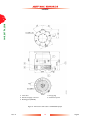
1. Vent valve
2. Electrical supply connector
3. Backing port (NW25)
4. Purge plug
5. Earth bond point
Figure 5 - Dimensions and features of EXT556H pumps
Issue A
18
Aug 05
EXT556H
The EXC controller provides the electrical supply to the EXT556H pump through the pump-to-controller cable.
Connect and lock the bayonet connectors at the ends of the cable to the mating connectors on the pump and
the EXC controller (if applicable).
It is the responsibility of the customer to ensure the stability of the system and the correct application of all
electrical and vacuum connections. It is also the responsibility of the customer to ensure that no service
connections present slip or trip hazards.
WARNING
Do not remove the EXDC controller/EXC controller cable from the pump until the pump has
come to a complete halt. To do so would expose personnel to hazardous voltages and potentially
damage the EXDC/EXC controller.
3.7
Cooling
3.7.1
Introduction
CAUTION
You must cool the pump by forced-air or water cooling to prevent damage to the bearing.
You must use water cooling in any of the following operating conditions:
• When backing pressure is high (see Table 5).
• When you bake the EXT pump or the vacuum system close to the pump.
• When the ambient temperature is above 35 °C.
• When there is high continuous gas throughput (see Table 5).
In all other operating conditions, you can use forced air cooling. If you use forced air cooling you must ensure
that there is an adequate supply of cooling air to the pump.
3.7.2
Forced air cooling
An air cooler accessory is available for the EXT556H pump (see Section 7). Fit the air cooler as described in the
instructions supplied with it. If you wish to use alternative air cooling, ensure that the flow rate is above 280 m3
h-1 (80 l s -1, 160 cfm).
Aug 05
19
Issue A
19
INSTALLATION
The EXC controller is designed to allow a pumping system to be configured in a variety of ways, from a basic
manually operated system to a fully automatic system with remote control. Refer to the instruction manual
supplied with the controller to complete the electrical installation.
PAGE
EXT556H
3.7.3
PAGE
20
Water cooling
A water cooling accessory is available for the EXT556H pump (see Section 7). Fit the water cooler as described
in the instructions supplied with it.
INSTALLATION
CAUTION
To prevent excessive thermal gradients from developing across the bearing, do not use thermal transfer paste
between the water-cooling accessory and the turbo-pump body.
CAUTION
Whilst pumping gases with rmm’s >28amu, or in the event that you are required to bake the pump, then you
must ensure that you limit the inlet and backing pressure according to the values given in Table 5.
The cooling water must comply with the specification given in Section 2.5. Pipes in the water cooling circuit may
become blocked if the cooling water contains too much calcium carbonate or if it contains particulates which
are too large. Corrosion of the water cooling circuit may occur if there is too little calcium carbonate or oxygen
in the water. Good quality drinking water is usually suitable for water cooling. If in doubt you must check the
quality of your cooling water supply and, if necessary, provide treatment and filtration.
Connect the cooling water supply to the water cooler as described below. Either of the riffled connectors can
be used for the water supply or return connections.
1.
Push reinforced hose (approximately 6 mm internal diameter) over the ends of the riffled hose connectors
on the water cooler.
2.
Attach the hose with strong hose clips and make sure that they are tightened securely.
3.
If the pump is mounted off the vertical, ensure that the water cooling plate connectors are positioned
below the electrical connector so that any leaking water does not drip onto it.
You must turn off the cooling water supply when you switch off the pump to prevent condensation of vapours
inside the pump. EXC controllers can operate a solenoid valve for this purpose. Refer to the controller manual
for details.
If you want to remove the pump for maintenance but do not want to break the cooling water circuit, unscrew
the fixing screws and remove the water cooler from the pump.
3.8
Magnetic Fields
WARNING
The EXT556HF variant will experience large attractive forces whilst in or near magnetic fields.
Ensure that the pump is firmly secured to the installation before presenting into a magnetic field.
Issue A
20
Aug 05
EXT556H
4
OPERATION
PAGE
21
WARNING
4.1
Start up
Use the following procedure to start up a basic manually controlled pumping system with a manual vent valve
and an EXC250 or EXC300 controller. Refer to the controller instruction manual.
1.
Turn the manual vent valve clockwise to close it.
2.
Turn on the cooling water supply (if cooling water is used) or switch on the power supply to the air cooler.
3.
Start the backing pump.
4.
When the vacuum system pressure is 10 mbar or less, use the controller start/stop button or the
appropriate signal command to the controller to start the pump.
5.
The pump will accelerate to full operating speed.
4.2
Stand-by
The EXC250 controller has a 95% speed standby option - this can be used to stop 'beating' between two
EXT556H pumps on a system. Refer to the controller manual for details.
The EXC300 also has a standby option, operated using the standby button on the front of the controller. This
runs the pump at 70% rotational speed. This can be used to allow system pressure to increase where this suits
a particular process. However, you should not run the pump in this mode for long periods of time, as the pump
is not designed to be run at this speed for its lifetime.
4.3
Shut-down
Use the procedure below to shut down a basic, manually controlled pumping system with a manual vent valve
and an EXC controller. Refer to the EXC controller instruction manual if the backing pump and accessories are
controlled by the EXC controller.
1.
Close the valve in the backing line connecting the EXT556H pump to the backing pump.
2.
Press the start/stop button on the EXC controller to switch off the EXT556H.
3.
When the EXT556H speed has fallen to 50% of full rotational speed, turn the manual vent valve
anticlockwise to open it. Ensure that the rate of pressure rise does not exceed the allowed rate of pressure
rise otherwise you can damage the pump - refer to Sections 3.4 and 2.3.
4.
If water cooling is in use, wait until the pump has come to a complete stop, then turn off the cooling water
supply.
5.
As the rotor turns freely and is spinning in a vacuum, if the pump is not vented at all the rotor will take
around 40 minutes to coast to a complete halt.
Aug 05
21
Issue A
OPERATION
Do not operate the EXT556H pump unless it is connected to your vacuum system. If you do the
pump rotor can cause injury. The pump rotor rotates at very high speeds and the rotating blades
might not be visible.
EXT556H
4.4
Safety interlocks and control system
WARNING
PAGE
22
When the power is restored following a power cut, the pump will restart automatically. The
pump must remain connected to the vacuum system to prevent risk of injury.
OPERATION
The pump protection and safety interlock features are listed below. Refer to the EXC/EXDC controller
instruction manual for a full description of these features.
• The EXC/EXDC controller monitors the temperature of the EXT pump and the electrical power
consumption of the pump. If the EXC controller detects excessive power consumption or temperature,
the rotational speed of the pump rotor is reduced until the power and temperature return to normal.
• If the rotational speed of a pump powered by an EXC controller is reduced to 50% of nominal speed,
then the pump is stopped immediately (or after a user defined time delay) and the Fail LED on the EXC
controller lights.
• If pump rotational overspeed is detected by the EXC Controller, the pump is stopped immediately and
the FAIL LED on the EXC Controller lights.
• The EXDC controller will not trip out into fail if the power or temperature limits are exceeded. Instead,
the rotational speed of the pump will continue dropping until the power and the temperature readings
come back within acceptable limits. In the case of rotational overspeed, the controller will reduce the
power until the pump returns to normal speed.
If the Fail LED lights, switch off the backing-pump immediately and vent the EXT pump. Once the EXT pump
has stopped, rectify the cause of the failure (refer to Section 5.5), press the EXC Controller Start/Stop button
to reset the Fail condition, and restart the EXT pump according to the guidelines in Section 4.1. If the pump is
hot, allow sufficient time for it to cool before you restart it.
4.5
Bakeout (conflat only)
CAUTION
If you bake the EXT556H pump you must use water cooling to prevent damage to the bearing lubricant. You
must also ensure that the temperature of the inlet flange does not exceed 100°C to avoid damage to the
bearing.
If you heat your EXT556H pump (and your vacuum system), you will speed up the degassing process so that
the pump will reach ultimate vacuum in the shortest possible time. If you heat the pump, this will also prevent
condensation of vapours inside the pump.
You can use the Edwards BX bakeout band to heat the pump (refer to Section 7). Fit the band around the pump,
just below the inlet-flange.
If you bake your vacuum system and the temperature of the system exceeds 110 °C, you must put a radiation
shield between the system and the EXT556H pump. This radiation shield will reduce the heat radiated onto the
pump rotor.
Typically, a bakeout of four hours is long enough to remove water condensation from the pump. However, the
bakeout time will depend on the amount of condensation in the pump and the vacuum system, and the ultimate
pressure you want to achieve.
Issue A
22
Aug 05
EXT556H
5
MAINTENANCE
PAGE
23
WARNING
5.1
Introduction
The maintenance operations for the EXT556H Turbomolecular pumps are described in the following sections.
The inlet-screen, the WCX water-cooler accessory and inlet-flange seals are available as spares (refer to
Section 7). Fit the ISX inlet-screen as described in Section 3.3.1. Fit the WCX water-cooler as described in
Section 3.7.3.
5.2
Bearing maintenance
When supplied, the pump contains sufficient lubricant to supply the bearings for life. No routine maintenance is
therefore required between bearing replacements. The bearings are not user-serviceable. The bearings will need
to be replaced when they reach the end of their service life. This is typically more than 20,000 hours, but may
be less; this depends on the type of pumping duty on which the pump is used.
When the bearings need replacement, we recommend that you exchange your pump for a factory reconditioned
replacement. Alternatively, you can send your pump to an Edwards Service Centre to have the bearings
replaced.
When you return EXT556H pumps to Edwards Service Centres please use the procedure included at the end
of this manual.
5.3
Rotor life
CAUTION
The fatigue life of EXT Turbo-pump rotors is typically 40,000 to 50,000 cycles. As a precautionary measure,
BOC Edwards recommends that pumps are returned for a major service (rotor replacement) after 20,000
cycles of rest to full speed and back to rest, or after 10 years use, whichever occurs first.
5.4
Clean the pump
CAUTION
Do not attempt to clean any parts of the pump other than external surfaces. Use of solvents may damage
internal pump components. Do not use abrasive materials on any surface of the HF variant.
If the EXT556H pump is contaminated inside, it may not be possible to achieve the specified ultimate vacuum,
or pump-down time may increase. The pump should be returned to a BOC Edwards Service Centre where the
pump will be dismantled and cleaned. Use the procedure included at the end of this manual.
Aug 05
23
Issue A
MAINTENANCE
Allow the pump-rotor to stop, then disconnect the EXC Controller before you remove the
pump from your vacuum system for maintenance or fault-finding procedures.
EXT556H
WARNING
PAGE
Clean the external surfaces of the pump in a well-ventilated location. When you use cleaning
solutions and solvents to clean the pump, observe all precautions specified by the manufacturer.
Avoid inhalation of any particulates which may be present in the pump.
24
MAINTENANCE
You can use any organic solvent to clean the external surfaces of your pump. We recommend that you use nonCFC solvents, such as isopropanol or ethanol. Use a cleaning solution which is suitable for the contaminants on
the pump surfaces.
For environmental reasons, keep wastage of cleaning solutions and solvents to a minimum.
5.5
Fault finding
Refer to Table 8 for the possible causes of faults and for the recommended actions to rectify faults. Table 8 is
applicable to a basic, manually controlled pumping system with an EXC Controller configured for local (manual)
operation.
Note that if you use an EXC Controller configured for remote operation to control the EXT556H pump, or if
you use an EXDC Pump Drive Module to control the EXT556H pump, some of the checks and actions in
Table 8 may not apply to your system.
Refer to the fault finding section of the instruction manual supplied with your EXC Controller or EXDC Pump
Drive Module for further fault finding information.
Symptom
The pump does not rotate. After
pressing start - Fail LED not lit.
Check
Action
Is the EXC Controller power LED If not, check that the electrical
lit?
supply is on, check that the switch
at the rear of the EXC Controller
is on, check the fuse in the rear of
the EXC Controller.
If all of the above are OK then the
EXC Controller is faulty. Consult
BOC Edwards or your supplier.
Is the EXC Controller Start/Stop
LED flashing?
If so, check that the correct links
are made on the EXC Controller
logic interface (refer to the
instruction manual supplied with
the EXC Controller).
Check that any system interlocks
are correctly made (refer to the
instruction manual supplied with
the EXC Controller).
Check that the pump-to-controller
lead is connected.
If all the above checks are OK then
consult BOC Edwards or your
supplier.
Table 8 - Fault finding
Issue A
24
Aug 05
EXT556H
Symptom
Check
Action
Is the EXC Controller first speed
indication LED lit?
If not, the EXC Controller is
faulty. If lit, then the EXT pump is
faulty. Consult BOC Edwards or
your supplier.
Ensure that the system interlocks
do not open after the EXT pump
has started.
The EXC Controller trips into Fail Is the inlet pressure too high? Is
during the ramp-up and before
the backing pressure too high?
50% speed is reached.
If so, reduce the pumping load, or
check for a gross leak into the
system.
Is the EXT pump running too hot? Increase the cooling or decrease
the gas load. (Refer to Section 2
for maximum inlet pressure and
cooling requirements). Check that
external heat sources (such as
system bakeout heaters) are not
excessive.
Does the rotor rotate freely?
If not, the EXT pump-bearings are
damaged. Consult BOC Edwards
or your supplier.
Is the timer set incorrectly?
Increase the timer setting (refer to
the instruction manual supplied
with the EXC Controller). If the
EXC Controller still trips into Fail
consult BOC Edwards or your
supplier.
The EXC Controller trips into Fail Is the pressure too high?
after 50% speed has been reached
- the first two speed LEDs are lit.
If so, reduce the pumping load or
check for a gross leak into the
system.
If the high gas load is temporary,
configure the EXC Controller to
delay the Fail trip on 50% speed
and set an appropriate delay time
(refer to the instruction manual
supplied with the EXC
Controller).
Is the EXT pump running too hot? Increase the cooling to the pump
or decrease the gas load.
Does the rotor rotate freely?
If not, the EXT pump-bearings are
damaged. Consult BOC Edwards
or your supplier.
The EXC Controller trips into Fail - all the speed LEDs are lit
Consult BOC Edwards or your
supplier.
Ultimate pressure cannot be
reached.
Bake the system and pump.
Is the pressure limited by water
vapour?
Table 8 - Fault finding (continued)
Aug 05
25
Issue A
25
MAINTENANCE
The EXC Controller trips into Fail Are the system interlocks
- at any speed.
correctly connected?
PAGE
EXT556H
Symptom
PAGE
26
Check
Action
MAINTENANCE
Are any of the vacuum gauges
contaminated?
If so, clean or replace them.
Is the pumping speed insufficient
(due to poor conductance
between the pump and the gauge
or too large a chamber)?
Increase the conductance or
reduce the volume.
Is the backing pressure > values
given in Table 7?
Check for backing line leaks. If the
backing pressure is too high, you
may need a larger backing-pump.
Is the high-vacuum area of the
system contaminated?
If so, clean the high-vacuum
system.
Check the rest of your system for If found, clean the contaminated
leaks and contamination.
areas and repair the leaks.
Remove the pump from the
system and test the ultimate
pressure of the pump alone (see
Section 3 for specification).
The EXT is very noisy or there is
excessive vibration or both.
If poor, check the pump for
contamination and if necessary
clean as described in
Section CAUTION. Leak-check
the pump. If the leak rate > 10-8
mbar l s-1
(10-6 Pa l s-1) consult BOC
Edwards or your supplier.
Is the pump rotational speed the
If so, change the natural frequency
same as the resonant frequency of of your system or isolate the pump
the attached system?
using flexible bellows.
Is the vibration being transmitted
from the rotary pump?
If so, fit flexible bellows or a
vibration isolator in the backing
line.
Is the noise irregular and getting
progressively worse?
If so, a bearing is defective. Switch
off the pump and consult BOC
Edwards or your supplier.
Is the EXT making a constant high- If so, the rotor might be out of
pitched noise?
balance. Consult BOC Edwards or
your supplier.
None of the above.
-
Consult BOC Edwards or your
supplier.
Table 8 - Fault finding (continued)
Issue A
26
Aug 05
EXT556H
6
STORAGE AND DISPOSAL
6.1
Storage
PAGE
27
Use the following procedure to store the pump.
Place protective covers over the inlet, outlet, purge and vent ports.
2.
Place the pump in its packing materials. For fastest pump-down when the pump is put back into service, seal
the pump inside a plastic bag together with a suitable desiccant.
3.
Store the pump in cool, dry conditions until required for use. When required, prepare and install the pump
as described in Section 3.
4.
Avoid long-term storage if possible. When long-term storage is necessary, the pump should be set up and
run for at least eight hours every six months.
6.2
Disposal
WARNING
In the unlikely event of a failure of the pump rotor, carbon fibre or rare earth magnet dust may
be generated. In this event, use appropriate Personal Protective Equipment when handling and
disposing of the pump, and ensure that all pump inlets and outlets are capped off before disposal.
Dispose of the EXT556H Turbomolecular Pump and any components and accessories safely in accordance with
all local and national safety and environmental requirements.
Particular care must be taken with any components which have been contaminated with dangerous process
substances.
Do not incinerate the pump. The pump contains phenolic and fluorosilicone materials which can decompose to
very dangerous substances when heated to high temperatures.
Aug 05
27
Issue A
STORAGE AND DISPOSAL
1.
EXT556H
PAGE
28
This page intentionally blank.
Issue A
28
Aug 05
EXT556H
7
SERVICE, SPARES AND ACCESSORIES
7.1
Introduction
PAGE
29
Order spare parts and accessories from your nearest BOC Edwards company or distributor. When you order,
please state for each part required:
• Model and Item Number of your equipment
• Serial number (if any)
• Item Number and description of the part
7.2
Service
BOC Edwards products are supported by a worldwide network of BOC Edwards Service Centres. Each Service
Centre offers a wide range of options including: equipment decontamination; service exchange; repair; rebuild
and testing to factory specifications. Equipment which has been serviced, repaired or rebuilt is returned with a
full warranty.
Your local Service Centre can also provide BOC Edwards engineers to support on-site maintenance, service or
repair of your equipment. Please ensure that all accessories (i.e. water/air cooler) are removed prior to
returning the pump for service.
For more information about service options, contact your nearest Service Centre or other BOC Edwards
company.
7.3
Spares
7.3.1
ISX inlet-screen
An inlet-screen is fitted to your pump as supplied to prevent damage from the entry of debris into the pump.
The Item Numbers of replacement inlet-screens are given in Table 9. There are two mesh sizes available - fine
and coarse. Select the mesh size appropriate to your requirements. The fine mesh (1 mm hole size) provides
better protection against falling objects e.g. fine pieces of filament, small grub screws. The coarse mesh (2 mm
hole size) gives better pumping performance. The coarse inlet screen is provided as standard.
Flange size
DN160ISO-K/DN160CF
Inlet-screen
Item Number
Inlet screen (coarse)
B580-51-007
Inlet screen (fine)
B580-51-008
Table 9 - ISX inlet-screen
Aug 05
29
Issue A
SERVICE, SPARES AND ACCESSORIES
BOC Edwards products, spares and accessories are available from BOC Edwards companies in Belgium, Brazil,
Canada, France, Germany, Hong Kong, Italy, Japan, Korea, Switzerland, United Kingdom, USA and a worldwide
network of distributors. The majority of these employ service engineers who have undergone comprehensive
BOC Edwards training courses.
EXT556H
7.3.2
PAGE
30
Inlet-flange seals
EXT pumps are supplied with an inlet seal. The Item Numbers of replacement seals are given in Table 10.
SERVICE, SPARES AND ACCESSORIES
Inlet-flange
Inlet seal
Item Number
DN160ISO-K
ISO160 trapped 'O' ring, fluoroelastomer
B271-58-172
DN160CF
Copper compression gasket (pack of 5)
C083-00-003
Table 10 - Inlet-flange seals
7.4
Accessories
7.4.1
Installation
The accessories available for use with the EXT556H turbomolecular pumps are described in the following
Sections. Figure 6 shows how the accessories are fitted to an EXT pump.
7.4.2
EXC controller
The Edwards EXC Controllers provide the facilities necessary for operating a pumping system based on an
EXT556H pump. The Item Numbers of the EXC Controllers are given in Table 11.
Controller
Voltage
Item Number
EXC250E
90 - 264 V ac
D396-35-000
EXC250L
90 - 264 V ac
D396-36-000
EXC300
90 - 132/180 - 264 V ac
D396-14-000
Table 11 - EXC controller
Issue A
30
Aug 05
EXT556H
PAGE
31
SERVICE, SPARES AND ACCESSORIES
1.
2.
3.
4.
5.
6.
7.
Vibration isolator
Bakeout band
Inlet flange seal (supplied)
Inlet screen (fitted)
EXT556H pump
TAV solenoid vent valve
DN10NW adaptor
8. Manual vent valve (fitted)
9. VRX vent restrictor
10. Vent port (supplied with
manual vent valve fitted)
11. WCX water cooling
accessory
12. Purge port
13. Purge plug (fitted)
14. DN10NW adaptor
15. PRX purge restrictor
16. Bakeout band position
17. ACX air cooler assembly
Figure 6 - Installation of EXT556H optional accessories and spares
Aug 05
31
Issue A
EXT556H
7.4.3
PAGE
32
Pump-to-controller cable
You must fit a pump-to-controller cable between an EXC Controller and the EXT pump. A cable is not supplied
with the EXT Pump or the EXC Controller (except EXC250L). The following cables are available:
SERVICE, SPARES AND ACCESSORIES
Cable
Length
Item Number
Pump-to-controller
1m
D396-18-010
Pump-to-controller
3m
D396-18-030
Pump-to-controller
5m
D396-18-050
Table 12 - Pump-to-controller cable
7.4.4
EXDC drive modules
Fit an EXDC Drive Module as an alternative to an EXC Controller and pump-to-controller cable.
Drive module
Item Number
EXDC160 80V
7.4.5
D396-41-000
Table 13 - EXDC drive modules
BX bakeout band (conflat only)
A BX bakeout band accelerates the degassing of the pump to enable it to achieve lower pressures. It may also
be used to protect the pump from condensation of contaminants. The bakeout bands are available in 110-120
V or 220-240 V versions and may be powered from a rear panel socket on the EXC Controller.
Pump
EXT556H/HF DN160CF
Bakeout band
Item Number
BX501 (110 V)
B580-52-044
BX501 (240 V)
B580-52-064
Table 14 - BX bakeout band
Issue A
32
Aug 05
EXT556H
7.4.6
FL20K foreline trap
The foreline trap minimises oil vapour backstreaming from the backing pump and is recommended where the
highest system cleanliness is required.
Item Number
FL20K
A133-05-000
Table 15 - FL20K foreline trap
7.4.7
TAV vent-valve and vent-port adaptor
Two solenoid-operated vent-valves are available for system venting. The valves are 24 V dc, normally-open, and
can be driven automatically from the EXC Controller. The solenoid-valve is fitted in place of the manual-valve,
or alternatively can be fitted with an adaptor (supplied with the valve) and be used with any suitable NW10
flanged port on your vacuum system.
The vent-port adaptor allows the vent-port or the purge-port to be used with any suitable NW10 fitting: refer
to Figure 6.
Product
Item Number
TAV5 vent-valve
B580-66-010
TAV6 vent-valve
B580-66-020
NW10-1/8 inch BSP
male adaptor
B580-66-011
Table 16 - TAV vent-valve and vent-port adaptor
7.4.8
ACX air-cooler
An ACX air-cooler can be fitted to the EXT pump. However, please refer to Section 3.7 and to Table 5 to check
the suitability of air-cooling in a particular application.
Pump
EXT556H/HF
Air-cooler
ACX555
Item Number
B580-53-561
Table 17 - ACX air-cooler
Aug 05
33
Issue A
33
SERVICE, SPARES AND ACCESSORIES
Foreline trap
PAGE
EXT556H
7.4.9
PAGE
34
WCX water-cooler
If you wish to water cool your pump, you must order the water cooling plate:
Water cooler
Item Number
SERVICE, SPARES AND ACCESSORIES
WCX555
B580-67-003
Table 18 - WCX water-cooler
7.4.10 Vibration isolators
In applications where the small amount of vibration generated by the turbomolecular pump is a problem, a
vibration isolator can be fitted. The isolator consists of two special flanges separated by a flexible bellows and
a rubber, anti-vibration, outer collar. The isolator required depends on the pump inlet-flange size.
Inlet-flange size
Item Number
DN160ISO-K
B580-49-000
DN160CF-K
B581-10-000
Table 19 - Vibration isolators
7.4.11 PRX purge-restrictor
A modified DN10NW centring-ring is available to filter the purge gas and restrict its flow rate to the
recommended flow of 25 sccm. The restrictor is suitable for all EXT pumps fitted with a purge-port.
Purge-restrictor
PRX10
Flange size
NW10
Item Number
B580-65-001
Table 20 - PRX purge-restrictor
7.4.12 VRX vent-restrictor
Use a VRX fixed orifice vent-restrictor to restrict the flow of vent gas into the EXT pump. Refer to Section 3.4
for information on the selection of the correct VRX vent-restrictor.
Vent-restrictor
Orifice diameter (mm)
Item Number
VRX10
0.1
B580-66-021
VRX20
0.2
B580-66-022
VRX30
0.3
B580-66-023
VRX50
0.5
B580-66-024
VRX70
0.7
B580-66-025
Table 21 - VRX vent-restrictor
Issue A
34
Aug 05