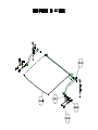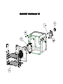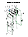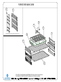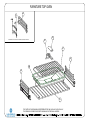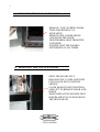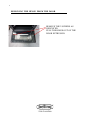
1
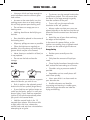
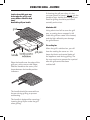
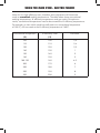
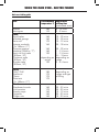
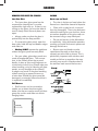
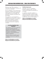
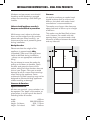
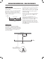
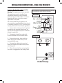
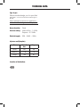
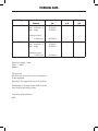
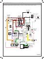
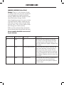
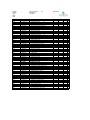
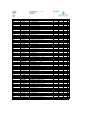
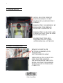
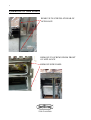
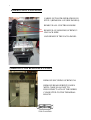
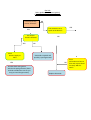
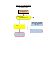
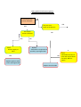
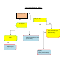
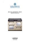
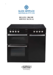
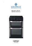
1 BELLING FSDF 60 DO SERVICE MANUAL 2 INDEX PRODUCT IDENTIFICATION PAGE APPLIANCE RATING PLATE ............................................................. 3 USER GUIDE AND INSTALLATION HANDBOOK USER GUIDE.......................................................................................... INSTALLATION INSTRUCTIONS....................................................... TECHNICAL DATA............................................................................... WIRING DIAGRAMS............................................................................. PARTS LIST FSDF 60........................................................................... 4-25 26-30 31-32 33-33 37-46 REPAIR AND MAINTAINANCE DISASSEMBLY PROCEDURES.......................................................... COMPONANT REMOVAL.................................................................. TECHNICAL SPECIFICATIONS......................................................... FAULTFINDING GUIDES................................................................... THIS MANUAL COVERS THE FOLLOWING MODELS :BELLING FSDF 60 DO AU 47-56 57-65 66-66 67-74 3 PRODUCT IDENTIFICATION Appliance rating plate location The appliance rating plate is located on the right-hand side of the front frame and also on the rear service panel 9 10 YEAR 4 1 8 MONTH 4 4 3 2 8 NUMBER OF PRODUCTION FOR THE MONTH 4 4 4 0 0 2 8 PRODUCT IDENTIFICATION CODE It is important that during all service calls the model and serial numbers are recorded on all paper work. Users Guide & Installation Handbook Belling Freestanding Dual Fuel AU OUR WARRANTY Should you need it . . . . Inside the paperwork which has come with this appliance, there is a leaflet and card explaining the terms of our extended warranty and guarantee. In order to apply for our five year guarantee, simply fill in the details on the card and post it off, this will register your appliance. Should you wish to take out extended warranty, please fill in the details on the leaflet and post this off to: Glen Dimplex Australia Unit 2, 205 Abbotts Road Dandenong South Victoria 3175 Australia Ph: 1300 556 816 Fx: 1800 058 900 Glen Dimplex New Zealand Pty 38 Harris Road, East Tamaki Auckland New Zealand Ph: 09 274 8265 Fx: 09 274 8472 If your appliance is covered by the warranty and guarantee, you will not be billed for work undertaken should your appliance be faulty, terms and conditions do apply, so please read through the literature carefully. Please ensure that you have available your appliances model number and serial number, there is a space at the back of this book for recording that information. IMPORTANT NOTICE Please note the cooling fan fitted to this appliance is an integral part of its safety and functionality. When the appliance is installed care must be taken that the cooling fans performance is not impeded by any objects coming into contact with it. (Installation pipes, leads etc) Care must also be taken that there is sufficient air flow at the rear of the appliance for the cooling fan to run at its optimum efficiency. (Particularly Built In appliances) See clearance dimensions in the installation section of the booklet. During use the Appliance must never be disconnected from the Mains supply as this will seriously affect the safety and performance of the appliance, particularly in relation to surface temperatures becoming hot and gas operated parts not working efficiently. The cooling fan is designed to run on after the control knob has been switched off to keep the front of the appliance and the controls cool until the appliance has naturally cooled itself. CONTENTS Introduction Before Using Safety Using the Hob Using the Grill Using the Ovens Cleaning Installation Technical Customer Care Please keep this handbook for future reference, or for anyone else who may use the appliance. INTRODUCTION Thank you for buying this British-built appliance from us. This guide book is designed to help you through each step of owning your new cooker, from installation to use. Please read it carefully before you start using your product, as we have endeavored to answer as many questions as possible, and provide you with as much support as we can. If, however, you should find something missing, or not covered, please contact our Customer Care team on: 0844 815 3746 For customers outside the UK and Northern Ireland, please contact your local supplier. When you dial this number you will hear a recorded message and be given a number of options. This indicates that your call has been accepted and is being held in a queue. Calls are answered in strict rotation as our Customer care representatives become available. Please ensure that you have the product’s model no and serial no available when you call. These can be found on the silver data label on your product. Alternatively, general information, spares and service information is available from our website: www.belling.co.uk Warranty Your new appliance comes with our 12-month guarantee, protecting you against electrical and mechanical breakdown. To register your appliance please call 0870 240 1914, complete the registration form included or register online at the address above. In addition, you may wish to purchase an extended warranty. A leaflet explaining how to do this is included with your appliance. Our policy is one of constant development and improvement, therefore we cannot guarantee the strict accuracy of all of our illustrations and specifications - changes may have been made subsequent to publishing. Gas warning If you smell gas: Do not try to light any appliance. Do not touch any electrical switch. Call the Gas Emergency Helpline at TRANSCO on: 0800 111999 BEFORE USING THE PRODUCT • Make sure that you have removed all packaging and wrapping. Some of the items inside this appliance may have additional wrapping. • It is advised that you turn the ovens and/or grill on for a short while. This will burn off any residues left from manufacturing. There may be a smell which accompanies this process - but this is nothing to worry about and is harmless. • It is recommend that you wash the oven shelves, baking tray, grillpan and grillpan trivet before their first use in hot soapy water. This will remove the protective oil coating. SAFETY GENERAL • Parts of the appliance may become hot while in use. Always make sure that children are supervised when they are near to the appliance. • The appliance must never be disconnected from the mains supply during use, as this will seriously affect the safety and performance, particularly in relation to surface temperatures becoming hot and gas operated parts not working efficiently. The cooling fan (if fitted) is designed to run on after the control knob has been switched off. OVEN/GRILL ✓ Always take care when removing food from the oven as the area around the cavity may be hot. ✓ Always use oven gloves when handling any utensils that have been in the oven as they will be hot. ✓ Always make sure that the oven shelves are resting in the correct position between two runners. Do not place the oven shelves on top of the highest runner, as this is not stable and can lead to spillage or injury. ✓ Always use the Minute Minder (if fitted) if you are leaving the oven unattended - this reduces the risk of food burning. ✗ Do not place items on the door while it is open. ✗ Do not wrap foil around the oven shelves or allow foil to block the flue. ✗ Do not drape tea towels near the oven while it is on; this will cause a fire hazard. ✗ Do not pull heavy items, such as turkeys or large joints of meat, out from the oven on the shelf, as they may overbalance and fall. ✗ Do not use this appliance to heat anything other than food items and do not use it for heating the room. GAS HOB ✓ Always ensure that pan bases are dry and flat before using them on the hob. ✓ Always position pans over the centre of the heat zone, and turn the handles to a safe position so they cannot be knocked or grabbed. ✓ Always use pans which are no smaller than 100mm (4”), or larger than 250mm (10”). ✓ Always match the size of pan to the size heat zone – do not use large pans on small zones or vice versa. ✓ Always make sure that the burner caps, rings and pansupports are correctly placed. This will prevent pans becoming unstable while in use and ensure an uninterrupted gas flow. ✗ Never use double pans, rim-based pans, old or misshapen pans, or any pan that is not stable on a flat surface. ✗ Never leave cooking fat, or oil, unattended. ✗ Never use commercial simmering aids, or heat diffusers, as they create excessive heat and can damage the surface of the hob. ✗ Never use the hob for any other purpose than cooking food. ✗ Plastic cooking utensils can melt if they come into contact with a warm hob. Never leave them close to, or on top of the hob. ✗ Never leave any heat zone alight without a pan covering it. This causes a fire hazard. SAFETY CHIP PAN FIRES What causes a chip pan fire? • Chip pan fires start when oil of fat overheats and catches fire, or when oil or fat spills on to the cooker because the pan has been filled too high. • They can also start when wet chips are put into hot oil, making it bubble up and overflow. Preventing a chip pan fire • Never fill the pan more than a third full with oil of fat. • Never leave the pan alone with the heat on - even for a few seconds. • Ensure chips are dry before putting them in the pan. • Never put chips in the pan if the oil has started smoking. Turn off the heat and leave the oil to cool down. In the event of a chip pan fire • If your chip pan does catch fire - don’t panic, and don’t move the pan. Serious burns are often caused by picking up the pan and running outside with it. • If it is safe to do so, and you don’t have to reach across the pan, turn off the heat. • Never throw water or use a fire extinguisher. • If you can, drape a damp cloth or towel over the pan to smother the flames. • Leave the pan to cool down for at least half an hour. • If you can’t control the fire yourself, close the door, get out and tell everybody else to get out. • Call the fire brigade. Don’t go back inside whatever the reason. USING THE HOB - GAS • Use pans which are large enough to avoid overflows onto the ceramic glass hob surface. • As soon as the water boils, turn the cooking zones down to a lower setting; this will help prevent pans boiling over. • Do not leave an empty pan on a heating zone. • To simmer, turn the control knob to the small flame symbol. This will ensure that the flame is just large enough to gently heat the contents of the pan. • To turn off, turn the control knob clockwise to the ‘off’ position. • Nothing should ever be left lying on the hob. • Always make sure that your pans are placed centrally on the burners and do not allow the flame to extend over the base of the pan. • Pans should be placed in the centre of the heating zone. • Avoid the use of pans that overhang the edges of the hotplate. • In the event of a power failure, or the ignition not working, then a lighted match or taper can be used to light the burner. Wipe any spillage as soon as possible. • Clean the hob top as regularly as possible, this will prevent any build up of grease which may be a fire hazard. Energy Saving • Never heat up a sealed tin of food, as it may explode. • Position pans centrally over the elements. • Do not use the hob surface for storage. • Only heat the amount of liquid you need. GAS HOB • Once liquids have been brought to the boil, reduce the heat setting to a simmer. Use • Consider using a pressure cooker if possible. • Vegetables cut into small pieces will cook more quickly. • Place your pan onto the pan supports above the burner you wish to use. • Use a pan which is a close match to your element size. • Push in and turn the selected control knob to the full on symbol (large flame). • Smaller elements are ideal for simmering and stewing in smaller pans, while the larger elements are ideal for frying and boiling. • If your hob has an ignition button or switch on the fascia, press it in until your burner lights. If your hob has automatic ignition it will spark automatically when you push in the control knob. • Hold the control knob in for 15 seconds then release. If the burner fails to light within this time, release the control knob and wait one minute before attempting to re-ignite. LID The Fold Down Lid Caution: Glass lids may shatter when heated. Turn off all the burners before shutting the lid. When opening and closing the lid, use the cooler outer sides of the lid glass. The lid must be opened fully, so there is no danger of it closing while the hob is being used. The appliance is fitted with a safety system, which will automatically turn off the hot plate burner controls if they are inadvertantly left on as the lid is closed. The lid is not intended to be used as a work surface, as it becomes hot when any part of the cooker is in use, and the surface may be scratched if items with rough or sharp surfaces are placed on it. USING THE GRILL - ELECTRIC Caution: Accessible parts may be hot when the grill is used, young children should be kept away. Detachable grill pan handle If cleaning the grill pan when it is hot, use oven gloves to move it. Do not use the handle to pour hot fats from the grill pan. Food for grilling should be positioned centrally on the trivet. Aluminium foil Using aluminium foil to cover the grill pan, or putting items wrapped in foil under the grill can create a fire hazard, and the high reflectivity can damage the grill element. The cooling fan When the grill is switched on, you will hear the cooling fan come on - this keeps the fascia and control knobs of the appliance cool during grilling. The fan may continue to operate for a period Place the handle over the edge of the grill pan, at the narrow side edges. Slide the handle to the centre, and locate between the handle position indicators. The handle should be removed from the pan during grilling, to prevent overheating. The handle is designed for removing / inserting the grill pan under the grill when grilling. after the grill control has been switched off. USING THE GRILL - ELECTRIC Using the grill When using the grill in the top oven, Caution: Accessible parts may the speed of grilling can be controlled be hot when the grill is used, by adjusting the grill setting or by young children should be kept selecting a higher or lower shelf position. away. For toasting, and for grilling foods The top oven grill has 3 heat settings such as bacon, sausages or steaks, as follows:- use a higher shelf position. For thicker foods such as chops or $<& * , * * Preheating For best results, preheat the grill for 3 - 5 minutes. To switch on the grill Open the top oven / grill door. Turn the top oven control knob to the required setting. Important: The door must be kept open when the grill is used. To switch off, return the control knob to the “off” position. For grilling smaller quantities of food the centre (economy) grill can be utilised. For grilling larger quantities of food, the full grill can be utilised. chicken joint pieces, use the low shelf position. USING THE TOP OVEN - ELECTRIC When you are cooking keep children away from the vicinity of the oven. Caution: The top element gets extremely hot when in use, so take extra care to avoid touching it. The top oven is a conventional oven. Note: The top oven is not controlled by the programmer. To turn on the top oven Turn the temperature control knob clockwise until the required temperature is selected. The red thermostat indicator will come on until the selected temperature is reached, and then go off; it will turn on and off periodically as the thermostat operates to maintain the selected temperature. To switch off, return the top oven control knob to the off position. Important: Never put items directly on the base of the oven, or cover the oven base with foil, as this may cause the element to overheat. Always position items on the shelf. The cooling fan When the top oven is switched on, you will hear the cooling fan come on - this keeps the fascia and control knobs of the appliance cool during cooking. The fan may continue to operate for a period after the oven control has been switched off. Preheating The oven must be preheated when cooking frozen or chilled foods, and we recommend preheating for yeast mixtures, batters, soufflés, and whisked sponges. Preheat the oven until the indicator light switches off for the first time, this will take up to 20 minutes depending on the temperature selected. If you are not preheating the oven, the cooking times in the following guide may need to be extended, as they are based on a preheated oven. Shelf positions There are 2 shelf positions which are counted from the bottom of the oven upwards, so shelf position 1 is the lowest. When cooking frozen or chilled food, use the highest possible shelf position, while allowing some clearance between the food and the top element. The oven shelf must be positioned with the upstand at the rear of the oven and facing up. Position baking trays and roasting tins on the middle of the shelves, and leave one clear shelf position between shelves, to allow for circulation of heat. When using the top oven As part of the cooking process, hot air is expelled through a vent at the top of the oven(s). When opening the oven door, care should be taken to avoid any possible contact with potentially hot air, since this may cause discomfort to peoplewith sensitive skin. We recommend that you hold the underneath of the oven door handle. USING THE TOP OVEN - ELECTRIC Top oven baking guide Cooking temperatures Cooking times The temperature settings and time given in the Baking Guides are based on dishes made with block margarine. If soft tub margarine is used, it may be necessary to reduce the temperature setting. If a recipe gives a different temperature setting to that shown in the guide, the recipe instruction should be followed. These times are based on cooking in a preheated oven. These cooking times are approximate, because the size and type of cooking dish will influence time as personal preferences. Because the top oven is more compact, it may be necessary to reduce cooking temperatures specified in recipes by up to 20°C. Shelf positions As a general guide, when cooking frozen or chilled food, use the highest possible shelf position, while allowing some clearance between the food and the top element. Follow the instructions given on packaging. Use the baking guide as a reference for determining which temperatures to use. Item Temperature °C Shelf position Approxiamte cooking time Small cakes Victoria sandwich (2 x 180mm / 7”) Swiss roll Semi rich fruit cake (180mm x 7”) Scones Meringues 180 160 1 1 15 - 20 mins 20 - 25 mins 200 140 1 1 8 - 12 mins 2¼ - 2¾ hours 215 90 - 100 1 1 10 - 15 mins 2 - 3 hours Shortcrust pastry Puff / flaky pastry Choux pasrty 200 - 210 200 - 210 200 - 210 1 1 1 Depends on size & type of cooking dish & also the filling Biscuits Sponge pudding Milk pudding 160 - 200 150 140 2 1 1 10 - 20 mins 30 - 45 mins 2 - 2½ hours USING THE MAIN OVEN - ELECTRIC FANNED Accessible parts may be hot when the oven is used. Young children should be kept away. To switch on the oven Turn the oven control knob to the required setting. The red thermostat indicator will come on until the selected temperature is reached and then go off; it will turn on and off periodically as the thermostat operates to maintain the selected temperature. Manual Operation The programmer must be set to manual operation before the main oven can be used. If A (Auto) is on the programmer display, return the oven to manual by pressing the up and down buttons simultaneously Any programmme which has been set is cancelled. The cooling fan To switch off, return the control knob to the “off” position. The cooling fan may operate when the main oven is on and may continue to operate for a period after the oven has been switched off. When using the oven Oven furniture As part of the cooking process, hot air is expelled through a vent at the rear of the oven. When opening the oven door, care should be taken to avoid any possible contact with potentially hot air, since this may cause discomfort to people with sensitive skin.We recommend that you hold the underneath of the oven door handle. Oven shelves The oven shelf must be positioned with the upstand at the rear of the oven and facing upwards. Position baking trays and roasting tins on the middle of the shelves, and leave one clear shelf position between shelves, to allow for circulation of heat. Baking tray and roasting tins Preheating When cooking sensitive items such as souffle and Yorkshire puddings or, when cooking bread, we recommend that the oven is pre-heated until the neon switches off for the first time. For any other types of cooking, a pre-heat is not required. For best cooked results and even browning, the maximum size baking trays and roasting tins that should be used are as follows; Baking tray 350mm x 280mm This size of baking tray will hold up to 16 small cakes. Roasting tin 370mm x 320mm We recommend that you use good quality cookware. Poor quality trays and tins may warp when heated, leading to uneven baking results. USING THE MAIN OVEN - ELECTRIC FANNED Slow cooking ( Setting) • Make sure that frozen foods are thoroughly THAWED before cooking. • Do not slow cook joints of meat or poultry weighing more than 2¼kg / 4½lb. • Preheat the oven to 170°C and cook for 30 minutes, then adjust the oven control to (slow cook setting) for the remainder of the cooking time. • Slow cooking times will be about 3 times as long as conventional cooking times. • Do not open the oven door unnecessarily during slow cooking, as this will result in heat loss at low temperatures. • Always use dishes with tightly fitting lids. To rectify badly fitting lids, place foil over the dish underneath the lid. Aluminium foil Use foil only to cover food or cooking dishes, using foil to cover the shelves or oven base creates a fire hazard. Cooking with a fanned oven As this is a high efficiency oven, you may notice the emission of steam from the oven when the door is opened. Please take care when opening the door. If you are used to cooking with a conventional oven you will find a number of differences to cooking with a fan oven which will require a different approach: There are no zones of heat in a fan oven as the convection fan at the back of the oven ensures an even temperature throughout the oven. This makes it ideal for batch baking - eg; when planning a party or stocking the freezer - as all the items will be cooked within the same length of time. Foods are cooked at a lower temperature than a conventional oven, so conventional recipe temperature may have to be reduced. Please refer to the conversion chart. Preheating is generally not necessary as a fan oven warms up quickly. There is no flavour transference in a fan oven, which means you can cook strong smelling foods such as fish at the same time as mild foods - eg; milk puddings. When batch baking foods that will rise during cooking - eg; bread - always ensure that enough space has been left between the shelves to allow for the rise. Notes: When 2 or more shelves are being used, it may be necessary to increase the cooking time slightly. Because the 2 oven shelves are wider than in many ovens, it is possible to cook 2 items per shelf - eg; 2 victoria sandwiches or 2 casseroles. Although you need to keep in mind the points ‘To help the air circulate freely’ with careful choice of dishes and tins, it is possible to cook a complete meal, and perhaps something else for the freezer, in the oven at the same time. When roasting meats, you will notice that fat splashing is reduced, which is due in part to the lower oven temperatures, and will help keep cleaning of the oven to a minimum. Because a fan oven has an even temperature throughout the oven, there is no need to follow the shelf positions given in the baking guide. There is no need to interchange dishes onto different shelves part way through cooking, as with a conventional oven. USING THE MAIN OVEN - ELECTRIC FANNED To help the air circulate freely Be safe Position the shelves evenly within the oven and maintain a clearance from the oven roof and base. Do not defrost stuffed poultry using this method. If more than one cooking dish or baking tray is to be used on a shelf, leave a gap of at least 25mm between the items themselves and the oven interior. Defrosting and cooling in the main oven To defrost frozen foods, turn the main oven control to the defrost position, place the food in the centre of the oven and close the door. To cool foods after cooking prior to refrigerating or freezing, turn the main oven control to the defrost position and open the door. Defrosting times Small or thin pieces of frozen fish or meat - eg; fish filets, prawns & mince will take approximately 1 - 2 hours. Placing the food in a single layer will reduce the thawing time. A medium sized casserole or stew will take approximately 3 - 4 hours. A 1½kg / 3lb oven ready chicken will take approximately 5 hours, remove the giblets as soon as possible. Do not defrost larger joints of meat and poultry over 2kg / 4lb using this method. Never place uncooked food for defrosting next to cooked food which is to be cooled, as this can lead to cross contamination. Defrosting meat, poultry, and fish can be accelerated using this method but make sure they are completely thawed before cooking thoroughly. Place meat and poultry on a trivet in a meat tin. Main oven baking guide Cooking times & temperatures The temperature settings and times given in the baking guide are based on dishes made with block margarine. If soft tub margarine is used it may be necessary to reduce the temperature setting. Allow enough space between shelves for food that will rise during cooking. Do not place items on the oven base as this will prevent air circulating freely. USING THE MAIN OVEN - ELECTRIC FANNED Note: this is a high efficiency oven, therefore some adjustment will have to be made to conventional cooking temperatures. The table below shows conventional cooking temperatures, ‘A’ efficiency temperatures and gas marks. For optimum results, conventional temperatures need to be converted to ‘A’ efficiency temperatures. For example, an item which would normally cook at a conventional temperature of 180 °C, will now cook at the ‘A’ efficiency temperature of 160°C. Conventional temperature ‘A’ Efficiency Oven Gas Mark (°C) (°C) 100 100 1/4 110 110 1/4 130 120 1/2 140 130 1 150 140 2 160 150 3 180-190 160 4-5 200 170 6 220 180 7 230 190 8 250 200 9 USING THE MAIN OVEN - ELECTRIC FANNED Main oven baking guide Dish Scones Meringues Cakes Small cakes Whisked sponge Swiss roll Victoria sandwich (2 x 180mm / 7”) Genoese sponge Madeira (180mm / 7”) Semi rich fruit cake (205mm / 8”) Christmas cake (205mm / 8”) Dundee cake (205mm / 8”) Pastry Flaky / Puff Shortcrust Choux Plate tarts (2 x 180mm / 7”) Biscuits Shortbread rounds Nut brownies Brandy snaps Flapjacks Ginger nuts Recommended Approximate temperature °C cooking time (preheated oven) 180 110 8 - 15 mins 2 - 3 hours 160 160 170 160 15 - 25 mins 15 - 20 mins 10 - 12 mins 20 - 30 mins 160 160 130 20 - 25 mins 1 - 1¼ hours 1 - 1¼ hours 2½ - 3 hours depending on depending on recipe recipe 130 2 - 2½ hours 180 170 170 170 depending on recipe and type of filling 160 170 160 160 160 25 - 35 mins 20 - 25 mins 10 - 12 mins 20 - 25 mins 10 - 20 mins USING THE MAIN OVEN - ELECTRIC FANNED Traditional fruit cakes Roast turkey It should be remembered that ovens can vary over time, therefore cooking times can vary, making it difficult to be precise when baking fruit cakes. Roasting turkey involves cooking two different types of meat - the delicate light breast meat, which must not be allowed to dry out, and the darker leg meat, which takes longer to cook. It is necessary therefore, to test the cake before removal from the oven. Use a fine warmed skewer inserted into the centre of the cake. If the skewer comes out clean, then the cake is cooked. The turkey must be roasted long enough for the legs to cook, so frequent basting is necessary. The breast meat can be covered once browned. • Follow the temperatures suggested in the recipe and then adjust accordingly to the conversion table. • Always make sure that the turkey is completely thawed and that the giblets are removed before cooking. • Do not attempt to make Christmas cakes larger than the oven can cope with, you should allow at least 25mm (1 inch) space between the oven walls and the tin. • Turkey should be roasted at 150°C - 160°C for 20 minutes per lb, plus 20 minutes, unless packaging advises otherwise. • Always follow the temperatures recommended in the recipe. • The turkey can be open roasted, breast side down, for half of the cook time, and then turned over for the remainder of the cooking time. • To protect a very rich fruit cake during cooking, tie 2 layers of brown paper around the tin. • We recommend that the cake tin is not stood on layers of brown paper, as this can hinder effective circulation of air. • Do not use soft tub margarine for rich fruit cakes, unless specified in the recipe. • Always use the correct size and shape of tin for the recipe quantities. • If the turkey is stuffed, add 5 minutes per lb to the cooking time. • If roasting turkey covered with foil, add 5 minutes per 1lb to the cooking time. To test if the turkey is cooked, push a fine skewer into the thickest part of the thigh. If the juices run clear, the turkey is cooked. If the juices are still pink, the turkey will need longer cooking. USING THE MAIN OVEN - ELECTRIC FANNED Notes: Roasting guide The times given in the roasting guide are only approximate, because the size and age of the bird will influence cooking times as will the shape of a joint and the proportion of the bone. Frozen meat should be thoroughly thawed before cooking. For large joints it is advisable to thaw over night. Frozen poultry should be thoroughly thawed before cooking. The time required depends on the size of the bird - eg; a large turkey may take up to 48 hours to thaw. Use of a trivet with a roasting tin will reduce fat splashing and will help to keep the oven interior clean. Alternatively, to help reduce fat splashing, potatoes or other vegetables can be roasted around the meat / poultry. • When cooking stuffed meat or poultry calculate the cooking time from the total weight of the meat plus the stuffing. • For joints cooked in foil or covered roasters, and for lidded casseroles, add 5 minutes per 450g (1lb) to the calculated cooking time. • Smaller joints weighing less than 1.25kg (2½lb) may require 5 minutes per 450g (1lb) extra cooking time. • Position the oven shelf so that the meat or poultry is in the centre of the oven. • It is recommended that the appliance is cleaned after open roasting. Cook in oven at: 160°C - Main Oven (Fanned) 180°C - Top Oven (Conventional) Approximate Cooking Time (preheated oven) Beef Rare Medium Well done 20 minutes per 450g (1lb), plus 20 minutes 25 minutes per 450g (1lb), plus 25 minutes 30 minutes per 450g (1lb), plus 30 minutes Lamb Medium Well Done 25 minutes per 450g (1lb), plus 25 minutes 30 minutes per 450g (1lb), plus 30 minutes Pork 35 minutes per 450g (1lb), plus 35 minutes Poultry 20 minutes per 450g (1lb), plus 20 minutes CLEANING GENERAL • It is important to clean the product regularly as a build up of fat can affect its performance or damage it and may invalidate your guarantee. • Always switch off your appliance and allow it to cool down before you clean any part of it. • Do not use undiluted bleaches, products containing chlorides, wire wool, abrasive cleaners or nylon pads. • Take extra care when cleaning over symbols on fascia panels. Excessive cleaning can lead to the symbols fading. Painted & Plastic parts • Only use a clean cloth wrung out in hot soapy water. • Do not use abrasive cleaners, such as “Cif”, wire or nylon cleaning pads on these parts. • Baby oil can be used to restore stainless steel finishes - but only use a few drops. Don’t use cooking oils as they can contain salts, which will damage the metal. • Do not use steam cleaners. Enamel surfaces & parts • Clean with warm, soapy water and a clean cloth. • If larger splashes of fat do not readily disappear, you can use a mild cream cleaner to remove them. More stubborn marks can be removed using a soap filled pad. • Rinse well and dry with a soft clean towel or cloth. • Do not use steam cleaners. Glass parts Stainless steel & Aluminium surfaces • Only use a clean cloth wrung out in hot soapy water, or a specialist glass cleaner. • Only use a clean cloth wrung out in hot soapy water, and dry with a soft cloth. • Rinse away any excess cleaner and dry with a soft cloth. • Stubborn marks can be removed using a stainless steel cleaner. Supplies can be purchased from the Customer Care Centre. • Do not use abrasives or polishes as they will scratch and damage the glass. • Sharp objects can mark the surface of stainless steel, but will become less noticeable with time. • Wipe any spillage immediately, taking care to avoid burning your hands. • Some foods are corrosive eg; vinegar, fruit juices and especially salt - they can mark or damage the metal if they are left on the surface. Chrome plated parts • Use a moist soap filled pad, or place in a dishwasher. CLEANING REMOVING OVEN PARTS FOR CLEANING GAS HOB Inner Door Glass Burner caps and heads • The inner door glass panel can be removed for cleaning but it must be replaced the right way up. If there is any writing on the glass, you must be able to read it clearly when the cavity doors are open. • The slots in the burner head where the flames burn should be cleared of deposits. • Always make sure that the glass is pushed fully into the Stop position. • To remove the glass panel, open the door wide, hold the top and bottom edges and slide out. • Warning: DO NOT operate the appliance without the glass panel correctly fitted. • For your safety, glass door panels are made of toughened glass. This ensures that, in the unlikely event that a panel breaks, it does so into small fragments to minimise the risk of injury. Please take care when handling, using or cleaning all glass panels, as any damage to the surfaces or edges may result in the glass breaking without warning or apparent cause at a later date. Should any glass panel be damaged, we strongly recommend that it is replaced immediately. Shelf Runners • Shelf runners can be removed to enable you to clean then thoroughly. Make sure they are cool to touch and then grasp the runners and slide out of their hanging holes. • Clean with a nylon brush, rinse and then dry thoroughly. There may be brown coloured markings on your burners; these are carbon deposits or fat stains and can be removed using a soap filled pad. • Do not put burners in the dishwasher or soak them. Using dishwasher powders, washing up liquids and caustic pastes can damage the burners. • Burner caps and heads must be repositioned correctly so that they sit squarely on to the hob as shown. This is particularly important with stainless steel models as failure to reposition the caps correctly may result in discolouration of the stainless steel around the burners. INSTALLATION INSTRUCTIONS - DUAL FUEL PRODUCTS Before you start: Please read the instructions. Planning your installation will save you time and effort. Prior to installation, ensure that the local distribution conditions (nature of the gas and gas pressure) and the adjustment of the appliance are compatible. The adjustment conditions are stated on the data badge. This appliance is not connected to a combustion evacuation device. It shall be installed and connected in accordance with current installation regulation. Particular attention shall be given to the relevant requirements regarding ventilation. Gas Safety (Installation & Use) Regulations This appliance must by an authorised person in accordance with the Australian Gas Installation Standard AS5601 the manufacturers installation instructions, local gas fitting regulations, and any other relevant statutory regulations. Particular attention should be given to relevant requirements regarding ventilation. Failure to install appliances correctly is dangerous and could lead to prosecution. Ventilation Requirements Ventilation must be as specified by AS 5601 Installation code. The room conatining the appliance should have an air supply. An appliance should be installed in a location for complete combustion of gas, proper flueing and to maintain ambient temperature of the immediate surrounding at safe limits, under normal conditions. Failure to install appliances correctly is dangerous and could lead to prosecution. INSTALLATION INSTRUCTIONS - DUAL FUEL PRODUCTS Windows and permanent vents should therefore not be blocked or removed without first consulting a GAS SAFE gas installer. Clearances Failure to install appliances correctly is dangerous and could lead to prosecution. The cooker must have a side clearance above hob level of 90mm up to a height of 400mm. Whilst every care is taken to eliminate burrs and raw edges from this product, please take care when handling - we recommend the use of protective gloves during installation. No shelf or overhang or cooker hood should be closer than a minimum of 650mm, but check with cooker hood manufacturer’s recommendations. This cooker may be fitted flush to base units. However, for models with side opening doors, we recommend a side clearance of 60mm between the cooker and any side wall. Moving the cooker Please note that the weight of this appliance is approximately 60kg (unpacked). Take care if the appli ance needs to be lifted during installation - always use an appropriate method of lifting. Do not attempt to move the cooker by pulling on the doors or handles. Open the door and grasp the frame of the cooker, taking care that the door does not shut on your fingers. Take care to avoid damage to soft or uneven floor coverings when moving the appliance. Some cushioned vinyl floor coverings may not be designed to withstand sliding appliances without marking or damage. Clearances & dimensions Appliance dimensions All sizes are nominal - some variation is to be expected. The ‘depth’ of the cooker, as given below, is to the front of the door & excluding knobs & handles. depth: width: height - lid down: height - lid raised: 600mm 500/550/600mm 900 - 915mm 1430 - 1445mm INSTALLATION INSTRUCTIONS - DUAL FUEL PRODUCTS Levelling Your Cooker A stability bracket can be fitted as follows: Place a spirit level on a baking sheet onto an oven shelf. Place the cooker in position and draw a PENCIL LINE level with the front edge (2). The cooker is fitted with LEVELLING FEET (1). Level your cooker to your desired height using the levelling feet at the front and rear of the cooker. Mark the centre of the cooker to give a CENTRE LINE (3). Remove the cooker and mark off 200mm to the right of the centre line (4) on the rear wall. Measure from FLOOR LEVEL to the ENGAGEMENT EDGE where the stability bracket will rest and add 2mm (5). Transfer this dimension to the rear wall and secure the bracket to the wall at this height (6) using the two off centre holes in the single bracket. Stability bracket If the cooker is fitted with a flexible connection, a stability bracket should be fitted to engage in the back of the cooker. A stability bracket can be bought from your local supplier. " ! INSTALLATION INSTRUCTIONS - DUAL FUEL PRODUCTS Connect to the electricity supply - Dual fuel Warning: This appliance must be earthed. The appliance must be installed by a competent electrician using a double pole control unit of 32 ampere minimum capacity with 3mm minimum contact separation at all poles. Your appliance will be fitted with one of the two terminal blocks below, Block A, Block B Block A # $ % We recommend that the appliance is connected by a qualified electrician who is a member of the N.I.C.E.I.C. and who will comply with the I.E.E. and local regulation. 1. Access to the mains terminal is gained by opening the terminal block cover at the rear of the appliance (use a small flatbladed screwdriver). 2. Connection should be made with 6.0mm2 flexible twin and earth cable. Block B 3. First strip the wires, then push the cable through the cable clamp in the terminal block cover. 4. Connect the cable to the terminal block and tighten the cable clamp screw (see diagram). 5. Close the terminal box, ensuring that the cover is engaged on the locking tabs. INSTALLATION INSTRUCTIONS - DUAL FUEL PRODUCTS Connect to the gas supply The inlet to the cooker is ½” BSP internal situated at the rear right corner. Fit the bayonet connection. This should be located so as to ensure that the flexible connector hose does not kink. Under no circumstances should the flexible connector be allowed to come into contact with the vertical oven flue tubes on the rear of the appliance. Use a 900mm - 1125mm length of flexible connector. Ensure that all pipework is of the correct rating for both size and temperature. Natural Gas - Flexible connections should comply with BS 669. Parts of the appliance likely to come into contact with a flexible connector have a temperature rise of less than 70°C. After installation, make sure all connections are gas sound. Commissioning Burner aeration All burners have fixed aeration and no adjustment is possible. Pressure setting Natural Gas @ 1.00kPa Hob burner - Turn the control knob to the FULL ON position, wait a second before pressing the ignition switch or holding a lighted match or taper to the burner. Hold the control knob in for 15 seconds. Do not hold the control knob in for longer that 15 seconds. If the burner fails to light within this time, release the control knob and wait one minute before attempting further ignition. Before leaving the installation 1. Place all the loose parts of the cooker into position. 2. Show the customer how to operate the cooker and give them this handbook. Thank you. TECHNICAL DATA Type of gas: Please see data badge your for specified gas type. * Can be converted from Natural gas to LP Gas Never attempt to convert an appliance unless the data badge states that you can. Burner Aeration: Fixed Pressure setting: Natural Gas - 1.0 kPa Propane - 2.75 kPa Electrical supply: 220 - 240V ~ 50Hz Injectors used (hotplate) Size Natural Gas LP gas Small 82 50 Medium 118 70 Large 142 87 Countries of destination: AUS TECHNICAL DATA Fuel Type Hotplate Burner / Element Nominal Rate Qn Butane g/h Propane g/h Natural Gas Hob - small Hob - medium x 2 Hob - large 3.2MJ/h 6.5MJ/h 9.5MJ/h - - •4 burners 25.7MJ/h - - Hob - small Hob - medium x 2 Hob - large 3.2MJ/h 6.5MJ/h 9.5MJ/h - - 25.7MJ/h - - Total heat input LP Gas Total heat input •4 burners Electrical supply / load 240v ~ 50Hz 4865w Dimensions All sizes are nominal so some variation ia to be expected. Warning: This appliance must ne earthed Databadge is located at the bottom of the front frame, behind the door. Countries of destination: AUS B elling FSDF 60 DO - AU Wiring Diagram ISSUE A Wiring colour code: Bk - Black, Bn - Brown, Bu - Blue, Gn - Green, Or - Orange, R - Red, W - White, Y - Yellow. TOP OVEN STAT. NEON Bk Bk TERMINAL BLOCK 410 Or Or Gn R THERMAL Y SWITCH 8 P8 7 P7 6 421 5 431 421 4 Y 3 2 408 Or 1 V 421 P6 P5 R Y Bn P4 MAIN OVEN STAT. NEON 579 MAIN OVEN THERMOSTAT & SWITCH P3 P2 Bk P1 Bu Bn 1 2 2 P2 W Gn 444 445 530 422 Y 435 Bk 592 Or IGNITION SWITCH Bk 404 516 R 438 W R 2 Bk Bn Y 437 1 444 407 Bn Bn 427 W 416 1 42.02400.008 Bn Bk TOP OVEN THERMOSTAT & SWITCH 42.03000.019 Or TOP OVEN THERMAL CUTOUT 404 P1 W R MAIN OVEN THERMAL CUTOUT 401 431 412 Bu Bn Gn Bk V Bk R OVEN STIR FAN Bk Bk COOLING FAN Bk BASE ELEMENT GRILL ELEMENT 444 414 Or 147 Y Y Y Gn 501 FAN OVEN ELEMENT 401 404 412 Or R 414 Gn MAIN OVEN LAMP Y 20 Gn 445 Bu Bk Bk GnGn Bu 435 L 501 Y 147 435 427 N Bk N TERMINAL BLOCK 438 R L 21 Gn Gn EARTH POINT EYELET 454 (2 off) HOTPLATE ELECTODES IGNITION GENERATOR 08 27494 00 01.2010 CUSTOMER CARE FAQs What parts of the appliance can be washed in a dishwasher? • Any enamelled parts such as the grillpan can be cleaned in a dishwasher, as can oven shelves and shelf guides. What parts must NOT be cleaned in a dishwasher? • Parts such as burner skirts and caps, control knobs and any cast iron items must not be cleaned in a dishwasher, they should be cleaned with hot soapy water and a nylon brush once they are cool enough. • Automatic cooking will normally produce condensation when the oven is cooling down with food inside. Should the cooling fan continue to run once the appliance has been switched off? • Yes. This is to make sure that you can always touch the control knobs to make temperature adjustments, and turn your appliance off. What is a Multifunction oven? • A multifunction oven combines a variety of features, which are explained fully earlier in this book, it allows you more flexibility when cooking. There’s been a power failure and the product won’t work. The neon on my appliance keep going out and coming back on again - is this right? • • Yes. In most cases the neon will cycle on and off to show that oven is maintaining your temperature choice. Switch off the electricity supply. • When the power returns switch the electricity supply back on and re-set any programmer/clock to the correct time of day. My oven is a single combined oven and grill - can I use both functions together? • No. You can only use one or the other. Why is there condensation on the doors? • Condensation is caused by hot, moist air meeting a cooler surface (i.e. the oven door). You cannot always prevent it, but you can minimise it when it happens by doing the following: o Pre-heat the oven at a high temperature before putting food in the oven, and cover the food you are cooking wherever possible. o Whenever you can, cook wet foods at higher temperatures. o Don’t leave food in the oven to cool down. Can all gas appliances be converted from Natural Gas to LP Gas? • Not all gas appliances can be converted. If Category II is stated on the databadge, then the appliance may be converted and a conversion kit must be obtained if not already provided. If in doubt, please contact Customer Care for further advice - do not attempt to convert an appliance if it is not compatible. Why won’t the ignition work? • Check there is a spark when the ignition button is depressed. If there is no spark, check the electricity supply is switched on at the socket. Check that the gas supply is switched on. CUSTOMER CARE CHANGING LIGHT BULBS (where fitted) Warning: There is a risk of electric shock, so always make sure you have turned off and unplugged your appliance before starting. Always allow the product to cool down before you change a bulb. Not all appliances have the same number and type of bulbs. Before replacing your bulb, open the oven door and see which type you have. Then use the table to help you change your bulb correctly. Bulbs can be purchased from hardware stores (always take the old bulb with you). Please remember that bulbs are not covered by your warranty. No of Lamps Bulb location Oven Type Instructions 2 Side All Remove the oven shelves. Grasp the lens cover on the light fitting and pull it away from the side of the oven. Unscrew the bulb and replace. Replace the lens cover 1 Rear Fanned/Multifunction Remove the oven shelves. Remove the loose oven back by unscrewing the 4 securing screws (one at each corner) and remove. Unscrew the lens cover by turning anticlockwise. Remove the bulb and replace. Replace the lens cover and oven back. 1 Rear Conventional Remove the oven shelves. Unscrew the lens cover by turning anticlockwise. Remove the bulb and replace. Replace the lens cover. CONTACT US Calling for a service If you should experience any problems with your cooker please contact your retailer or place of purchase. Important note: Service work is to be conducted by authorised persons only. It is also adviseable that your cooker is checked regularly and maintained in good condition. An annual maintenance is recommended. Always check the instruction book before calling a service agent to make sure you have not missed anything. Glen Dimplex Australia Pty Ltd Customer Care: Tel: Australia 1-300-556-816 New Zealand 09-274-8265 Before you contact a service agent, make sure that you have the following information to hand: Model Number Serial Number Date of Purchase Postcode Glen Dimplex Australia, Unit 2, 205 Abbotts Road, Dandenong, South Victoria 3175, Australia e-mail: [email protected] web: www.glendimplex.com.au Model Names: Belling FSDF 08 27495 00a 02 2010 PRODUCT: COLOUR: CODE: ISSUE: DATE: Key 00358 00783 0211 0314 0349 0697 0880 0882 0108 0210 0294 0315 0544 0728 0734 0791 0880 0881 0912 0108 0287 0293 0467 0508 0511 0728 0734 0876 0912 0001 0056 0056 0083 0084 0085 0102 0103 0104 0178 0281 0552 0580 0728 0736 0803 0876 0888 0889 0894 BEL FSDF 60 DO AU Stainless Steel 444440493 Product 073103224 602925404 082360801 082291500 082233400 081830501 562044130 082914200 082808902 073103427 081586001 602598709 082971302 081581800 926016900 080180676 081797200 082554300 081545403 082558101 082558001 073103618 081586001 082971200 082971801 082852401 082972400 083000500 080180676 081797200 083045300 082558001 073103828 503003000 082922401 082922400 082519304 082519406 082519506 082957700 082957701 082957702 082520000 082532602 502427500 082938800 083011900 081423974 082303400 083007700 082964506 082964505 082964604 Sta Product Description CHASSIS fs 60 df do FRONTFRAME 60 std mot SLEEVE silicone (black) COVER flue vent FAN cooling DP203A-2123LST-C31 FOOT levelling long PLINTH 60 blk SWITCH thermal cutout L120C SWITCH thermal fan MAIN OVEN fs 60 df fan light BUSH cavity support FANCOVER 60 flue lamp mot ELEMENT oven fan 20.35719.010 FAN oven circulation LAMP assy oven SCREW m6x30 pp mc SEAL main ov 550HL KB SPACER oven fan SWITCH thermal cut-out 150c SWITCH m/ov 42.02400.008 THERMOSTAT EGO 55.17069.090 TOP OVEN fs 60 df fg BUSH cavity support Element gr/dual 20.35715.000 Element base 20.35727.000 HOLDER phial INSULATION top oven back INSULATION top oven elec 12mm SCREW m6x30 pp mc SEAL main ov 550HL KB SWITCH t/ov 42.03000.030 THERMOSTAT EGO 55.17069.090 HOB MECH 60 g lid au ACTUATOR arm HINGE BRKT ASS SBS RH(RIVETTD) HINGE BRKT ASS SBS LH(RIVETTD) BURNERBOWL aux (injector 0.82) BURNERBOWL s/rapid (inj 1.18) BURNERBOWL rapid (inj 1.42) BURNERSKIRT aux (serie 3) BURNERSKIRT semi (serie 3) BURNERSKIRT rapid (serie 3) CLIP spring Defendi ELECTRODE 1300mm DEL703 LID clip NUT flanged locking SCREW no2 x 5/8" pz pan bzp SEAL tap 4mm COPRECI F3862-04 SPRING lid rs2 SWITCH thermocouple TAP semi 0.39 bp lh set 52-54A TAP aux 0.32 bp lh set 52-54A TAP semi 0.39 bp rh set 52-54A FREESTANDING TCO Replace Date Qty 1 1 1 1 1 4 1 1 1 1 2 1 1 1 1 2 1.6 3 1 1 1 1 2 1 1 1 1 1 2 1.2 1 1 1 2 1 1 1 2 1 1 2 1 4 4 2 4 4 4 2 4 1 1 1 PRODUCT: COLOUR: CODE: ISSUE: DATE: Key 0895 0909 0979 0050 0545 0574 0147 0392 0458 0459 0738 0823 00455 0392 0738 0835 0182 0420 0421 0749 0182 0411 0420 0421 0427 0749 0967 0057 0247 0303 0304 0428 0057 0256 0303 0304 0428 0090 0091 0092 0111 0472 0551 0614 0032 0114 0299 0299 0322 0525 BEL FSDF 60 DO AU Stainless Steel 444440493 Product 082964606 083007500 083007600 073104830 503071200 082964901 082964900 073104001 082533800 083001000 082979700 082979701 080180734 082494402 073104201 082905901 083001001 080180734 082963200 073104409 082101600 082917304 082917305 082917403 073104607 082101600 602517700 082917300 082917301 082283705 082917403 082518800 073107500 561776724 073105501 083006000 013009702 082557900 082557901 562989812 073106001 083006000 013009602 082557900 082557901 702989812 073105004 082957800 082957801 082957802 056900900 602895007 012903901 082249902 073106591 082566102 081811301 083003103 083003102 013009516 083000900 Sta Product Description TAP rapid 0.45 bp rh set 65-70 THERMOCOUPLE THERMOCOUPLE wire FACIA MECH fs 60 ang df BRACKET neon FS DF LENS neon NEON lamp assembly MAIN DOOR MECH fs 60 CATCH roller (nylon) GLASS inner fs 60 main HINGE bottom door HINGE top door SCREW m4x12 tt pcsk ch blk STRIKER door (silver) TOP DOOR MECH fs 60 do HINGE drop down door (Zan) GLASS inner fs 60 top SCREW m4x12 tt pcsk ch blk Counter support FURNITURE MAIN 60 stop CLIP tubular GUIDE shelf large lh 1978 GUIDE shelf large rh 1979 SHELF main oven 452 wide 1970 FURNITURE TOP 60 stop CLIP tubular GRILLPAN std mot GUIDE shelf small lh 1974 GUIDE shelf small rh 1975 HANDLE grill pan 1041 SHELF main oven 452 wide 1970 WIRE TRIVET grill pan 1130 SIDE PANELS blk Outerside MAIN DOOR AES fs 60 be Sta BRACKET door handle DOOR assy 60 main be sta END CAP LH door ext Blk END CAP RH door ext Blk HANDLE door be 60 sta TOP DOOR AES fs 60 be do sta BRACKET door handle DOOR assy 60 top be sta END CAP LH door ext Blk END CAP RH door ext Blk HANDLE door be 60 sta HOB AES 60 g wire lid-be blk BURNERCAP aux (serie3)blk gls BURNERCAP semi (serie3)blk gls BURNERCAP rapid(serie3)blk gls BUTTON hotplate Blk HOTPLATE 60 gas fsd lid be blk LID glass assy 60 blk PANSUPPORT wire fs 55/60 FACIA AES fs be 60df blk BEZEL switch nic BUTTON switch ENDCAP facia rh matt black ENDCAP facia lh matt black FACIA assy be 60 fs dfdo blk KNOB cont bi-gas fs-gasBlk/Chr FREESTANDING TCO Replace Date Qty 1 4 4 1 2 2 2 1 1 1 1 1 4 1 1 2 1 2 2 1 2 1 1 2 1 2 1 1 1 1 1 1 1 2 1 2 1 1 1 1 1 2 1 1 1 1 1 1 2 1 4 1 1 2 1 2 2 1 1 1 6 PRODUCT: COLOUR: CODE: ISSUE: DATE: Key 0878 0040 0478 0424 BEL FSDF 60 DO AU Stainless Steel 444440493 Product 081811101 073107029 083029900 081273002 081150200 073107680 082749500 Sta Product Description SWITCH ignition E2009 WIRING fs df do BLOCK terminal PA223Sn/3 Connector 3 way GENERATOR ignition DG111 LABELS be 60df au HANDBOOK Bel FSD AU FREESTANDING TCO KB Replace Date Qty 1 1 1 1 1 1 1 FREESTANDING DF HOTPLATE ASSEMBLY 0614 0091 0092 0103 0091 0090 0103 0102 0104 0111 0472 0084 0909 0083 0084 0281 0085 0929 0912 0889 0876 0887 0888 0876 C O This diagram is the property of GLEN DIMPLEX HOME APPLIANCES Not to be reproduced or transmitted in any shape or form without permission of GLEN DIMPLEX HOME APPLIANCES. 0420 0421 0420 0421 7 FURNITURE MAIN OVEN 422 422 410 427 967 ALTERNATIVE SHELF GUIDES- KEY NUMBER FOR OPPOSITE HAND 421 421 411 422 749 THE PARTS ON THIS DRAWING ARE REPRESENTATIVE ONLY AND MAY VARY VISUALLY. THIS DRAWING IS GENERIC AND PARTS SHOWN MAY NOT BE ON ALL MODELS. FURNITURE TOP OVEN 419 419 410 ALTERNATIVE SHELF GUIDES - KEY NUMBER FOR OPPOSITE HAND 420 427 967 420 411 419 749 THE PARTS ON THIS DRAWING ARE REPRESENTATIVE ONLY AND MAY VARY VISUALLY. THIS DRAWING IS GENERIC AND PARTS SHOWN MAY NOT BE ON ALL MODELS. 1 BELLING FSDF 60 DO REPAIR AND MAINTAINANCE PROCEDURES 2 IMPORTANT BEFORE CARRYING OUT ANY SERVICING WORK ALWAYS DISCONNECT FROM THE ELECTRICAL SUPPLY 3 1) REMOVING THE MAIN OVEN DOOR REMOVE THE 2 SCREWS FROM THE LOWER HINGE AS INDICATED. REMOVE THE LOWER HINGE AND SLIDE THE DOOR DOWNWARDS AWAY FROM THE TOP HINGE ENSURE THAT THE DOOR IS SUPPORTED AT ALL TIMES 2) REMOVING THE TOP OVEN DOOR OPEN THE DOOR FULLY RELEASE THE 2 CLIPS AND PUSH FULLY BACK INTO POSITION SHOWN CLOSE DOOR TO REST POSITION AND LIFT TO REMOVE DOOR AND HINGE WHEN REPLACING ENSURE THAT HINGES ARE FULLY ENGAGED IN THE HINGE BUSH 4 REMOVING THE HINGE FROM THE DOOR REMOVE THE 2 SCREWS AS INDICATED PULL THE HINGE OUT OF THE DOOR EXTRUSION 5 3) LID REMOVAL WITH LID IN THE UPRIGHT POSITION REMOVE 2 SIDE PLATES BY LOOSENING THE 2 SCREWS REMOVE THE 2 LID SPRINGS BY RELEASING THE SPRINGS FROM THE LOWER HOLES REMOVE THE 2 LID CLIPS AND CAREFULLY LIFT THE LID AWAY FROM THE HOBTOP ENSURE THAT THE LID IS SUPPORTED AT ALL TIMES AFTER REMOVAL OF THE LID 4) HOB TOP REMOVAL REMOVE 4X HOTPLATE BUTTONS AS SHOWN (2 ON EITHER SIDE) LIFT THE HOB TOP AWAY WHEN REPLACING ALWAYS ENSURE THAT THE HOB TOP LOCATES BENEATH THE FACIA PANEL AND THAT THE BURNER BOWLS LOCATE IN THE HOLES CORRECTLY 6 5) REMOVAL OF SIDE PANELS REMOVE 2X SCREWS AT REAR OF APPLIANCE REMOVE 2X SCREWS FROM FRONT OF APPLIANCE REMOVE SIDE PANEL 7 6) REMOVAL OF FACIA PANEL CARRY OUT BOTH OPERATIONS IN STEP 5 (REMOVAL OF SIDE PANELS) REMOVE ALL CONTROL KNOBS REMOVE 4 X HOLDING SCREWS 2 ON EACH SIDE AND REMOVE THE FACIA PANEL 7) REMOVING THE REAR SERVICE PANEL REMOVE SECURING SCREWS X6 REMOVE REAR SERVICE PANEL WITH CARE SO AS NOT TO DISCONNECT ANY OF THE WIRES CONNECTED TO THE TERMINAL BLOCK 8 REAR SERVICE PANEL REMOVED COOLING FAN GRILL ELEMENT LOWER OVEN ELEMENT MAIN OVEN ELEMENT MAIN OVEN STIR FAN 8) DOOR SEALS THE DOOR SEAL IS REMOVED BY JUST PULLING IT IS SECURED IN THE GAP BETWEEN THE CAVITY AND FRONTFRAME AND REQUIRES NO OTHER FIXING TO REFIT PUSH IN ALWAYS ENSURE THAT DOOR SEAL LIP IS FACING CORRECT WAY 9 9) GAINING ACCESS UNDERNEATH HOBTOP THE HOB TOP CAN BE REMOVED WITHOUT REMOVING THE LID USING THE FOLLOWING PROCEDURE REMOVE THE 2 SCREWS HOLDING THE SIDE PANEL REPEAT FOR L/H SIDE PANEL REMOVE THE CONTROL KNOBS GENTLY PULL THE SIDE PANEL AWAY FROM THE APPLIANCE AND REMOVE THE 2 FACIA PANEL SECURING SCREWS REMOVE THE 4 HOTPLATE BUTTONS AS SHOWN IN STEP 4 10 THE HOB TOP MAY NOW BE LIFTED TO GAIN ACCESS TO THE GAS TAPS/ THERMOSTATS/ELECTRODES ETC TAKE CARE TO ENSURE THAT THE HOB TOP IS SUPPORTED AT ALL TIMES WHEN WORKING UNDERNEATH WHEN REFITTING ALWAYS ENSURE THAT THE BURNER BOWLS PROTRUDE THROUGH THE HOLES IN THE HOB TOP FULLY 11 REPLACEMENT OF COMPONANTS A) ELECTRODES FOLLOW STEP 8( PAGE 9 ) AND REMOVE THE HOB TOP REMOVE ELCTRODE CLIP BY SQEEZING TOGETHER AND PULLING TO REMOVE REMOVE ELECTRODE FROM BURNER BOWL AND IGNITION LEAD FROM IGNITIION GENERATOR ON REPLACING ALWAYS ENSURE THAT THE RUBBER WASHER IS REFITTED B) HOB THERMOCOUPLES FOLLOW STEP 8 (PAGE 9) AND REMOVE THE HOB TOP REMOVE UPPER NUT USING A 7mm SPANNER REMOVE THE THERMOCOUPLE FROM THE BURNERBOWL AND DISCONNECT FROM HOB SHUT-OFF MICROSWITCH ON REPLACING ALWAYS ENSURE THAT THE RUBBER WASHER IS REPLACED TO REDUCE DISTURBANCE TO THE FLAME DUE TO THE COOLING FAN 12 C) COOLING FAN FOLLOW STEP 8 (PAGE 9) AND REMOVE THE HOB TOP REMOVE THE 4 SECURING SCREWS AND REMOVE THE FAN AND FAN GUARD DISCONNECT THE WIRES WHEN RE-FITTING ALWAYS REFIT THE FAN GUARD 13 D) GAS TAPS FOLLOW STEP 8 (PAGE 9) LIFT HOB TOP FOLLOW STEP 6 (PAGE 7) REMOVE FACIA PANEL REMOVE 1 SCREW AS SHOWN ON EITHER SIDE PULL FORWARD INNER FACIA PANEL TO GAIN ACCESS TO THE 2 TAP SECURING SCREWS UNDO BUNDY TUBE CONNECTION AND REMOVE DISCONNECT THERMOCOUPLE REMOVE 2 GAS TAP SECURING SCREWS AND REMOVE THE TAP WHEN REPLACING TAP ALWAYS ENSURE THAT A NEW TAP WASHER IS FITTED (part number 081423974) 14 E) THERMOSTATS FOLLOW STEP 9AND THE LIFT THE HOB TOP PULL THE T/STAT OUT OF THE SWITCH HOUSING DISCONNECT THE T/STAT PHIAL FROM INSIDE THE OVEN CAVITY (R/H SIDE OF CAVITY IN BOTH OVENS AND PULL THROUGH TO REMOVE T/STAT FULLY 15 F) TIMER FOLLOW STEP 6 (PAGE 7) REMOVE FACIA PANEL RELEASE TIMER FROM HOLDING CLIPS BY GENTLY PUSHING IN CLIPS WITH A SCREWDRIVER 16 G) DOOR SEAL THE DOOR SEAL IS REMOVED BY JUST PULLING IT IS SECURED IN THE GAP BETWEEN THE CAVITY AND FRONFRAME AND REQUIRES NO OTHER FIXING TO REFIT PUSH IN ALWAYS ENSURE THAT DOOR SEAL LIP IS FACING CORRECT WAY H) GRILL ELEMENT FOLLOW STEP 7 REMOVE REAR SERVICE PANEL DISCONNECT WIRES REMOVE GRILL ELEMENT GUARD BY LOOSENING 2 HIDDEN SCREWS (POSITIONS INDICATED ) AND SLIDING OFF REMOVE 2 SECURING SCREWS FROM ELEMENT BRACKET AND REMOVE FROM CAVITY BY PULLING FORWARD 17 I) TOP OVEN LOWER ELEMENT REMOVE INSULATION AT THE BACK OF THE TOP OVEN CAVITY REMOVE SCREW FROM INSIDE TOP OVEN CAVITY AS INDICATED PULL ELEMENT FROM REAR OF APPLIANCE ALWAYS ENSURE WHEN REPLACING INSULATION TO USE CORRECT TAPE 18 J) MAIN OVEN ELEMENT FOLLOW STEP 7 AND REMOVE THE REAR SERVICE PANEL REMOVE 4 X REAR FAN COVER SECURING SCREWS AND REMOVE FAN COVER DISCONNECT WIRING REMOVE THE 2 ELEMENT SECURING SCREWS AND PULL ELEMENT FORWARD INTO THE CAVITY 19 K) MAIN OVEN STIR FAN FOLLOW STEP 7 AND REMOVE THE REAR SERVICE PANEL REMOVE THE REAR FAN COVER AS ON PREVIOUS PAGE REMOVE THE FAN IMPELLOR N.B L/H THREAD NEEDS TO TURNED CLOCKWISE TO REMOVE DISCONNECT WIRING FROM FAN REMOVE 3 X STIR FAN SECURING SCREWS AND REMOVE FAN FROM THE REAR OF THE APPLIANCE L) MAIN OVEN LIGHT FITTING FOLLOW STEP 7 REMOVING REAR SERVICE PANEL REMOVE GLASS LAMP COVER BY UNSCREWING REMOVE THE EARTH LEAD RELEASE 4 XCLIPS HOLDING LIGHT FITTING IN PLACE REMOVE BY PULLING LIGHT FITTING FORWARD INTO CAVITY 20 TECHNICAL SPECIFICATIONS NOMINAL RESISTANCES AT 20oC *5,//(/(0(17,11(5 287(5 : : 72329(1/2:(5(/(0(17 : 0$,129(1)$1(/(0(17 : 0$,129(167,5)$1 &22/,1*)$1 N OVERHEAT CUT-OUTS TOP 120oC REAR 150oC FAN RUN-ON 60oC 21 BELLING FSDF 60 DO AU FAULTFINDING GUIDES Single Electric Cooker Main Fan oven not working Nothing working at all? Is the Timer working? No Check fuse or supply turned on Yes Is the clock set to manual? YES Is there a neon on the facia? Advise customer on setting the timer Yes No Is the neon on? NO Replace Thermostat. YES NO Does oven Stir fan run? possible fault with motor and switch. YES Does the oven heat up? Yes Appliance working OK NO No Fault with element. Electric Multi function oven Main oven not working Nothing working at all? No Is the Timer working? Check fuse or supply turned on Yes Is the clock set b to manual? YES Has the customer selected the correct function and set the thermostat? No NO Advise customer on how to use oven functions. Advise customer on setting the timer Yes NO Do any of the selected functions work? No Possible fault with Selector switch. Yes Does fan NO oven work? No Which part of oven not working? Fan or Element? Replace failed part Yes Does the Conventional No oven heat up? No Do either of the top or bottom elements work? Yes Replace failed part Yes No Are ovens working OK, and only certain functions not working? Fault with the selector switch Yes Diagnose faulty part and replace i.e. Lamp assy or Top heat not working,replace top element. Gas Hob Faulty ignition (Automatic ignition) Customer states no ignition to burner/s Is more than one burner affected? NO Can You see a spark at the burner? YES Are all four burners affected YES YES NO NO NO check electric supply to hob? Send engineer order electrodes required and Ignition switch (micro switch) clean and make sure burner skirt and cap are fitted correctly. If this does not work. YES Replace spark generator Replace electrode and ignition switch ( micro switch) Gas Hob Faulty ignition (Push button ignition) Customer states no ignition to burner/s Is more than one burner affected? NO Are all four burners affected YES check electric supply to hob? NO NO electrodes required and possibly a spark generator YES Possible fault with ignition switch and spark generator (these could be combined as one so you may just need the generator). YES Can customer see a spark at the burner? YES NO Replace electrode clean and make sure burner skirt and cap are fitted correctly. Did this work?. Gas hob with thermocouples Hob burner will not stay lit Burner won’t stay on when control knob released keep the control knob depressed for 10 secs. NO YES Advise customer control knob must be kept depressed for at least 10 secs is the thermocouple probe is in the flame YES Replace thermocouple and or gas tap. NO clean burner skirt and cap also to make sure they are correctly fitted. Faulty ignition (Push button ignition) Customer states no ignition to burner/s Is more than one burner affected? NO Are all four burners affected YES check electric supply to hob? YES Can you see a spark at the burner? YES NO NO Replace electrodes as required and possibly a spark generator YES NO Replace ignition switch and or spark generator Replace the electrode clean and make sure burner skirt and cap are fitted correctly. Did this work?. Faulty ignition (Automatic ignition) Customer states no ignition to burner/s Is more than one burner affected? NO Can you see a spark at the burner? YES YES Are all four burners affected YES NO NO NO check electric supply to hob? clean and make sure burnerskirt and cap are fitted correctly. If this does not work. Replace electrodes as required andIgnition switch (micro switch) YES Replace spark generator Replace electrode and or ignition switch ( micro switch)