1
AD-8922A
Remote Controller
INSTRUCTION MANUAL
1WMPD4002022
© 2009 A&D Company Ltd. All rights reserved.
No part of this publication may be reproduced, transmitted, transcribed, or translated
into any language in any form by any means without the written permission of A&D
Company Ltd.
The contents of this manual and the specifications of the instrument covered by this
manual are subject to change for improvement without notice.
CONTENTS
1 INTRODUCTION .................................................................................................................................... 2
1-1 Outline .......................................................................................................................................................2
1-2 Applicable Instruments ..............................................................................................................................2
1-3 Compliance................................................................................................................................................3
2 DESCRIPTION OF EACH PART ............................................................................................................ 4
2-1 Display .......................................................................................................................................................5
2-2 Key Operation............................................................................................................................................5
2-3 Connectors ................................................................................................................................................5
3 GETTING READY................................................................................................................................... 6
3-1 Setting the Weighing Instrument and the AD-8922A.................................................................................6
3-2 Connecting the AD-8922A .........................................................................................................................6
3-3 Turning the Power on ................................................................................................................................7
3-4 Operation ...................................................................................................................................................7
3-5 Example of Use .........................................................................................................................................7
4 FUNCTION SETTINGS........................................................................................................................... 9
4-1 Display and Keys .......................................................................................................................................9
4-2 Function Table .........................................................................................................................................10
4-3 Initialization ..............................................................................................................................................12
5 TROUBLESHOOTING.......................................................................................................................... 13
6 SPECIFICATIONS ................................................................................................................................ 14
7 RS-232C SERIAL INTERFACE ............................................................................................................ 15
8 EXTERNAL DIMENSIONS ................................................................................................................... 16
9 OPTIONS.............................................................................................................................................. 17
9-1 Confirming the AD-8922A Software Version............................................................................................17
9-2 Installing the Option .................................................................................................................................18
10 BCD OUTPUT (AD-8922A-01) ......................................................................................................... 19
10-1 BCD Output Specifications...................................................................................................................19
10-2 Setting of the Decimal Point Position...................................................................................................24
11 COMPARATOR OUTPUT (AD-8922A-04)........................................................................................ 25
11-1 Comparator Output Specifications .......................................................................................................25
11-2 Using the Comparator Output ..............................................................................................................27
11-3 Setting the Upper and Lower Limit Values...........................................................................................28
12 CURRENT LOOP INPUT (AD-8922A-05)......................................................................................... 30
12-1 Current Loop Input Specifications........................................................................................................30
13 ANALOG OUTPUT (AD-8922A-06).................................................................................................. 32
13-1 Analog Output Specifications ...............................................................................................................32
13-2 Function setting....................................................................................................................................34
13-3 Switching Output Voltage.....................................................................................................................35
13-4 Output Voltage Fine Adjustment ..........................................................................................................35
13-5 Fixed Output Voltage ...........................................................................................................................36
14 ACCESSORIES (CABLE LIST) ........................................................................................................ 37
1
1 INTRODUCTION
The AD-8922A is a remote controller. Read this manual completely before using the AD-8922A in order to
ensure a sufficient understanding for proper use.
1-1 Outline
The AD-8922A is connected to an A&D manufactured weighing instrument, using the RS-232C serial interface.
Displays the weighing data transmitted by the weighing instrument.
Key operations remotely control the weighing instrument.
(Entering the function setting mode of the weighing instrument is not available. Available operations
depend on the weighing instrument used. See Table 2 in "1-2 Applicable Instruments".)
The data the AD-8922A receives can be output, using the RS-232C serial interface. So, external
devices such as a personal computer or a printer can be connected to the AD-8922A.
Can be panel-mounted.
Various options such as BCD output, comparator output, current loop input and analog output are
available. For details, refer to "9 OPTIONS" and the following relevant chapters.
When connected to the AD-4212C, the AD-8922A can change the response characteristic, calibrate
the AD-4212C using the external weight, and both instruments can share power.
(Power can be supplied to both instruments by plugging the AC adapter into either the AD-4212C or
the AD-8922A. For details, refer to "3-3 Turning the Power on ".)
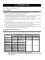
1-2 Applicable Instruments
Applicable weighing instruments and what is required are shown in the table below.
Table 1 Applicable weighing instruments and what is required
What is required to connect to
Cable required to connect to
a weighing instrument
an external device such as
Personal
AD-8121B
Option for the Communications cable*
(Length 2 m)
computer
compact printer
instrument
None
None
AD-4212C
(Use
the cable provided
(D-Sub 9-pin)
for AD-4212C)
GX, GF, GX-K,
None
AX-KO1710-200
GF-K, GP, FP,
AD-4212A/B, GR, HR (D-Sub 25-pin)
EK-i, EW-i, FC-i, None
AX-KO2466-200
FC-Si, GH, HR-i, (D-Sub 9-pin)
FZ-i, FX-i
EK-G, EK-H,
OP-03
ET-W, EW-G
(D-Sub 25-pin) AX-KO1710-200
AX-KO1786-200 AX-KO462-200
HV-G, HV-WP,
None
AX-KO1786-200
HW-G, HW-WP
(DIN 7-pin)
OP-03
FG
AX-KO1786-200
(DIN 7-pin)
OP-03
FS, FS-KL
AX-KO1786-200
(DIN 8-pin)
OP-23
FG-L, FG-M
AX-KO1786-200
(DIN 8-pin)
Note (*) - The standard communications cable is AX-KO1710-200. A substitute communications
cable may be provided as specified when ordering the AD-8922A.
- When connecting to the AD-4212C, use the AX-KO3590-500 (5m) cable, provided as standard
for the AD-4212C.
Weighing
instrument
2
The AD-8922A functions in two ways as follows, depending on the weighing instrument used:
A remote controller that displays the weighing data and remotely controls the weighing instrument.
A remote display that displays the weighing data.
Available key operations depend on the weighing instrument used, as shown below. Set the command set
"C5et" of the function setting, appropriate to the weighing instrument.
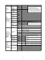
Table 2 Applicable weighing instruments and key operations
Weighing
instrument
AD-4212C
GX, GX-K, GP,
GH, ET-W, FZ-i
GR
ON:OFF
CAL
Calibrates
using the
external
Turns the mass.
weighing Calibrates
instrument using the
display
internal
on or off. mass.
*1
AD-8922A key
SAMPLE
PRINT
Switches
the
minimum Outputs
the
display.
received
*2
data to
an
external
device.
*3
⎯
MODE
RE-ZERO
Switches
the
response
characteristic.
Switches
the unit
displayed.
*4
Sets the
display to
zero.
Command
set *5
C5et 1
C5et 1
C5et 2
GF, GF-K,
EK-H,
⎯
C5et 3
AD-4212A/B, HR,
HR-i, FX-i
EK-i, EW-i
⎯
⎯
C5et 4
EK-G, EW-G, FC-i,
FC-Si, FG, FG-L,
FG-M, FP, FS, FS-KL,
⎯
⎯
⎯
⎯
⎯
C5et 0
HV-G, HV-WP, HW-G,
HW-WP
Note: "⎯" in the table indicates that the key operation is not available.
*1: Switching the standby or weighing mode is available for the AD-4212C.
*2: Not applicable to the counting mode and the percent mode. Switching the minimum display
is not available for the ET-W.
*3: Available when the AD-8922A is in key mode ("out 1" or "out 2" of the function setting).
*4: Not available for the ET-W and AD-4212
*5: AD-8922A function settings
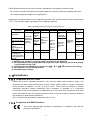
1-3Compliance
1-3-1 Compliance with FCC Rules
Please note that this equipment generates, uses and can radiate radio frequency energy. This
equipment has been tested and has been found to comply with the limits of a Class A computing
device pursuant to Subpart J of Part 15 of FCC rules.
These rules are designed to provide
reasonable protection against interference when equipment is operated in a commercial
environment. If this unit is operated in a residential area, it may cause some interference and under
these circumstances the user would be required to take, at his own expense, whatever measures
are necessary to eliminate the interference.
(FCC = Federal Communications Commission in the U.S.A.)
1-3-2 Compliance with EMC Directives
This device features radio interference suppression in compliance with valid EC
Regulation 89/336/EEC.
3
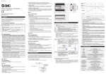
2 DESCRIPTION OF EACH PART
Main unit
Display
Keys
Angle adjustment knob
Connector
to the external device
(DIN 8-pin )
Rear
AC adapter
jack
Connector
to the weighing instrument
(D-Sub 9-pin )
Grounding terminal
Stand
Accessories
AC adapter
AC adapter identification label
See Note below.
Communications cable
to connect to a weighing
instrument (Length: 2 m, 1 pc.)
D-Sub 25-pin to D-Sub 9-pin
(AX-KO1710-200)
Note: Please confirm that the AC adapter type is correct for your local voltage and receptacle
type.
A substitute communications cable, listed below, may be provided as specified when
ordering the AD-8922A.
• D-Sub 9-pin to D-Sub 9-pin (AX-KO2466-200)
• DIN 7-pin to D-Sub 9-pin (AX-KO1786-200)
When connecting to the AD-4212C, use the cable provided for the AD-4212C.
Do not use the cable provided for the AD-8922A.
4
2-1 Display
Displays the weighing data and the unit (or mode) received. The unit (or mode) may be different from
that of the weighing instrument.
Turns on the stabilization indicator when the header of the weighing data received is "ST", "QT", or "WT".
Turns on the comparator indicator when the comparison results are added to the data received.
Applicable to GX-K, GF-K, GP and AD-4212A/B. (Function setting "Cp-r")
When nothing has been received for two seconds or more, the bar display [- - - - -] appears. By
changing the function setting, the previous data received is displayed until the next data is received
(Hold display). During the hold display, the hold indicator is turned on.
Note: When the data is in eight digits, the highest-order digit is displayed in the upper left
corner as shown below.
For example, if the weighing data is 101.00000 g, the display is like
.
2-2 Key Operation
Available key operations to control the weighing instrument depend on the weighing instrument used. For
details, see Table 2 in " 1-2 Applicable Instruments".
Set the command set "C5et" of the function setting, appropriate to the weighing instrument.
To enter the function setting mode of the AD-8922A, press and hold the ON:OFF key and press the CAL
key.
The weighing instrument has its own function settings and the AD-8922A can not change those settings.
2-3 Connectors
2-3-1Connector to the weighing instrument (BALANCE / SCALE) ... D-Sub 9-pin male
Used to connect to the weighing instrument. The cable used for connection depends on the instrument.
For details, refer to the instruction manual of the weighing instrument.
2-3-2Connector to the external device (PC / PRINTER) ... DIN 8-pin female
Used to connect to an external device such as a personal computer or a printer (AD-8121B). The cable
used for connection depends on the device. For details, refer to the instruction manual of the device.
5
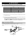
3 GETTING READY
3-1 Setting the Weighing Instrument and the AD-8922A
1. Set each item as shown below. Set the same value for the weighing instrument and the AD-8922A.
Table 3
Item
Baud rate
Data bits, Parity bit
Stop bits
Terminator
Data format
Communication control
Data output mode
Weighing instrument
AD-8922A
600, 1200, 2400, 4800, 9600. 19200 bps
7 bits - EVEN, 7 bits - ODD, 8 bits - NONE
1 bit or 2 bits
<CR> or <CR><LF>
A&D standard format
⎯
No RTS/CTS control
⎯
Stream mode*
⎯
Items in bold face type: Factory settings for both the AD-8922A and the weighing instrument.
* When connected to an external device, the settings can be changed to suit the use.
2. Set the command set "C5et" of the function setting, appropriate to the weighing instrument. See Table 2
in "1-2 Applicable Instruments".
Note: Some items may not be available for the instrument used. For details on setting, refer to
the instruction manual of each weighing instrument.
When connected to an external device such as a personal computer or a printer, set the output
mode "out" and time out "Hold" of the function setting, and set the data output mode of the
weighing instrument, appropriate to the use. (See Table 3 in "3-5 Example of Use".)
3-2 Connecting the AD-8922A
For information on cables required for connection, see Table 1 in " 1-2 Applicable Instruments".
Connect the weighing instrument to the AD-8922A D-Sub 9-pin connector.
Connect an external device such as a personal computer or a printer to the AD-8922A DIN 8-pin
connector.
6
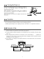
3-3 Turning the Power on
Insert the AC adapter plug into the AC adapter jack located on
the rear of the AD-8922A. Plug the AC adapter into an
appropriate electrical outlet.
When connected to the AD-4212C, power can be supplied to
both instruments by plugging the AC adapter into either the
AD-4212C or the AD-8922A.
(Both instruments can have their AC adapter connected at the
same time.)
3-4 Operation
The AD-8922A displays the weighing data transmitted by the weighing instrument used.
The AD-8922A key operations remotely control the weighing instrument.
Available operations depend on the weighing instrument. See Table 2 in "1-2 Applicable Instruments".
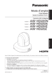
3-5 Example of Use
A personal computer is connected to the AD-8922A and the weighing data can be transmitted to the
personal computer, using Windows communication tools (WinCT).
To protect against inadvertent operations, the AD-8922A keys can be disabled. (Function setting
"C5et 0").
When nothing has been received for two seconds or more, the bar display [- - - - -] appears. By
changing the function setting, the previous data received is displayed until the next data is received
(Hold display). (Function setting "Hold 1 ")
About details on the settings of the weighing instrument or the external device, see the relevant
instruction manual.
AD-8922A
PC/PRINTER
Used to connect to
the external device
BALANCE/SCALE
Used to connect to
the weighing instrument
External device
AD-8121B
Personal computer
PLC
Weighing
instrument
7
Table 4 Use of the AD-8922A
Example
of use
Weighing
instrument
AD-8922A setting
Through mode "out 0"
Monitors the
weighing data
of the
weighing
instrument
remotely.
Stream mode
(Outputs the
Key mode 1
weighing data
continuously.)
"out 1"
Key mode 2
"out 2"
Sends all of the
received weighing
data to the external
device.
When the AD-8922A
PRINT key is
pressed, sends the
latest weighing data
received to the
external device,
regardless of the data
status.
When the AD-8922A
PRINT key is
pressed, sends the
latest weighing data
received to the external
device when the data is
stable.
External device
setting
[AD-8121B]
MODE 2
(Prints data in
conjunction with
theAD-8121B
DATA key or
interval setting.)
[AD-8121B]
MODE 1
(Prints data when
the AD-8121B
DATA key is
pressed.)
Key mode or
[AD-8121B]
Auto print mode
MODE 1
(Outputs the
Sends all of the
(Prints data
weighing data
received weighing
according to the
when the key Through mode "out 0"
data to the external
data output
is pressed or
device.
mode of the
outputs the data
weighing
automatically
instrument.)
when stable.)
Monitors the
Command
[Personal computer
weighing data mode *
or PLC]
Sends all of the
of the
(Outputs the
(The program to
received weighing
weighing
weighing data Through mode "out 0"
data to the external
control the
instrument that by the data
device is
device.
is built into a
request
required.)
weighing system. command.)
* The command mode may not be available for weighing instruments of which command is always
valid.
8
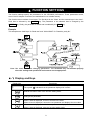
4 FUNCTION SETTINGS
The function settings specify the parameters for the AD-8922A performance. These parameters stored,
even if the AC adapter is removed, are maintained in non-volatile memory.
The function menu consists of two layers. The first layer is the “Class” and the second layer is the “Item”.
Each item is selected by the SAMPLE key. The parameter of the selected item is changed by the
RE-ZERO key. Finally, the parameter is stored and is enabled by the PRINT key.
Example
This example sets “9600 bps” for “Baud rate” and “8 bits NONE” for “Data bits, parity bit”.
Note: Use much care when changing parameters. The AD-8922A may not function properly
when the settings and operational environment are not appropriate.
4-1 Display and Keys
Table 5
Display/Key
Description
The symbol “
” indicates that the parameter displayed is in effect.
Selects the class or item in the function setting mode.
Changes the parameter.
When a class is displayed, moves to an item in the class.
When an item is displayed, stores the new parameter and displays the next class.
When an item is displayed, cancels the new parameter and displays the next class.
When a class is displayed, exits the function setting mode.
9
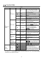
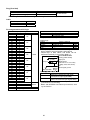
4-2 Function Table
Table 6
Class
Item
Parameter
0
Set 0
1
Set 1
2
Set 2
3
Set 3
4
Set 4
0
Through mode
1
Key mode 1
2
Key mode 2
0
Bar display
1
Hold display
0
Not used
1
At intervals
2
Used
dpp
0
Not set
5apl
6
0
C5et *
Command set
out
Output mode
fnc
Environment
Display
Hold
Timeout
bep
Data receipt
buzzer
Position of
decimal point
Function of the
SAMPLE key
Set
No function
Description
When connected to EK-G, EW-G,
FC-i, FC-Si, FG, FP, FS, FS-KL
HV-G, HV-WP, HW-G or HW-WP.
Disables the AD-8922A keys for use
as a remote display.
When connected to ET-W, GH, GP,
GX, GX-K, FZ-i, AD-4212C.
When connected to a GR series
balance.
When connected to GF, GF-K,
AD-4212A/B, HR, HR-i. EK-H, FX-i
When connected to an EK-i/EW-i
series balance.
Always outputs the data received by
the D-Sub 9-pin connector, to the
DIN 8-pin connector.
Outputs the latest data received by
the D-Sub 9-pin connector, to the
DIN 8-pin connector, when the
AD-8922A PRINT key is pressed.
Outputs the latest stable data
received by the D-Sub 9-pin
connector, to the DIN 8-pin
connector, when the AD-8922A
PRINT key is pressed.
Bar display if nothing has been
received for two seconds or more.
Displays the previous data received
if nothing has been received for two
seconds or more, and turns on the
hold indicator.
No buzzer upon data receipt.
Sounds buzzer when the data is
received with an interval of two
seconds or more.
Sounds buzzer upon each data
receipt.
Sets the decimal at a specific position. When
changing the minimum display digit, pressing
SAMPLE key does not change the decimal
point position. (For details, refer to “9-2”.)
The SAMPLE key does not function.
1
Function
The SAMPLE key will function.
0
600 bps
Choose a parameter appropriate to
1200 bps
1
the weighing instrument.
5if
2400 bps
2
When the AD-8121B compact
bp5
Serial
printer is to be connected, leave the
Baud rate
4800
bps
3
interface
factory settings of the AD-8922A as
9600 bps
4
is and set the weighing instrument.
19200 bps
5
Factory setting
* See Table 2 in "1-2 Applicable Instruments" to set the command set "C5et" of the function setting,
appropriate to the weighing instrument.
10
Class
Item
btpr
5if
Serial
interface
Data bits
Parity bit
5top
Stop bits
Crlf
Terminator
data
data
polp
bcd
BCD
Available only
when the
BCD output
is installed.
Polarity
5tbp
Stability
0erp
Over
5trp
Strobe
5trt
Strobe pulse
width
5trp
(Input terminal
function)
Cp fnc
Cp
Comparator
Comparator mode
Available only
when the
comparator
bep
output is
LO buzzer
installed.
bep-
OK buzzer
bep
HI buzzer
aout
Analog
output
Available only
when the
analog output
is installed.
an
Analog output
mode
5el
Analog output
digit selection
Parameter
0
1
2
0
1
0
1
0
1
0
1
0
1
0
1
0
1
0
1
2
Description
7 bits - EVEN
7 bits - ODD
8 bits - NONE
1 bit
2 bits
CR/LF
CR
Class
Choose a parameter appropriate to
the weighing instrument.
When the AD-8121B compact
printer is to be connected, leave the
factory settings of the AD-8922A as
is and set the weighing instrument.
ON when 0
ON when 1
ON when positive or 0
ON when negative
ON when the stabilization indicator is turned off
ON when the stabilization indicator is turned on
OFF when e or -e
ON when e or -e
Data refresh is complete when ON → OFF
Data refresh is complete when OFF → ON
Approx. 10 ms
Approx. 20 ms Strobe pulse width after data refresh
Approx. 50 ms
0
BUSY input function
1
0
RE-ZERO input function
No comparison
Comparison, excluding "near zero" when the value is
1
stable or overloaded
Comparison, including "near zero" when the value is
2
stable or overloaded
Continuous comparison, excluding "near zero"
3
Continuous comparison, including "near zero"
4
Contact-outputs the second header information of the data
5
received. (Applicable to AD-4212A, GP and GX-K)
OFF
0
Selects whether or not to sound the buzzer
when LO.
ON
1
OFF
0
Selects whether or not to sound the buzzer
when OK.
ON
1
OFF
0
Selects whether or not to sound the buzzer
when HI.
ON
1
2-digt
Converts the consecutive 2 digits, with the digit
0
output selected in 5el as the least, to voltage and outputs.
3-digt
Converts the consecutive 3 digits, with the digit
1
output selected in 5el as the least, to voltage and outputs.
Selects the first digit as the least.
0
Selects the second digit as the least.
1
Selects the third digit as the least.
2
Selects the fourth digit as the least.
3
Selects the fifth digit as the least.
4
Selects the sixth digit as the least.
5
Factory setting
11
4-3 Initialization
Initialization restores the AD-8922A function settings to factory settings.
1. Connect the AC adapter. The bar display or the weighing data
display appears.
2. While pressing and holding the ON:OFF key, press the PRINT
key. "Clr" appears in the display.
3. Press the PRINT key. (To cancel the operation, press the CAL
key.)
4. Press the RE-ZERO key to select "go".
5. Press the PRINT key to perform initialization.
After initialization, the bar display or the weighing data display
appears.
12
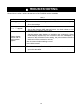
5 TROUBLESHOOTING
Shown below is a list of various phenomena of the AD-8922A and the remedies.
Table 7
Phenomenon
error10 appears.
Cause and remedy
• The communications settings of the AD-8922A and the weighing
instrument are not the same.
Check the settings.
• The weighing instrument data format is incorrect.
error11 appears.
The bar display
remains and no
weighing data
appears.
Set the data format to A&D standard format. Also check whether or not
data other than weighing data is output.
• Is the weighing instrument in the stream mode?
Only the stream mode displays the weighing data continuously. Other
modes display the data only when received. When the hold display is
selected in the AD-8922A function setting, the previous data received is
displayed until the next data is received.
• Are the communications settings correct?
• Is the cable correct?
• Electrical noises may affect the display.
The display flickers.
Using the grounding terminal located on the rear of the AD-8922A,
ground the AD-8922A.
13
6 SPECIFICATIONS
Power supply
: AC adapter
(Please confirm that the AC adapter type is correct for your local voltage
and receptacle type.)
Power consumption
: Approx.11 VA (Including the AC adapter, AD-8922A: approx. 1.5 VA)
Transmission system
: RS-232C
Baud rate
: 600, 1200, 2400, 4800, 9600, 19200 bps
Refresh rate
: Approx. 10 times/second (When Baud rate is 2400 bps or greater).
Applicable connectors
: D-Sub 9-pin (Male) to connect to the weighing instrument
DIN 8-pin (Female) to connect to an external device
Dimensions
: 238 (W) x 132 (D) x 170 (H) mm
Mass
: Approx. 1.0 kg
Standard accessories
: AC adapter, Communications cable (Approx. 2 m)
(Please confirm that the AC adapter type is correct for your local voltage
and receptacle.)
14
7 RS-232C SERIAL INTERFACE
RS-232C
Transmission system
Transmission form
Data format
:
:
:
EIA RS-232C
Asynchronous, bi-directional, half duplex
Baud rate
: 600, 1200, 2400, 4800, 9600, 19200 bps
Data bits
: 7 bits or 8 bits
Parity bit
: EVEN, ODD
(Data bits 7 bits)
NONE
(Data bits 8 bits)
Stop bits
: 1 bit or 2 bits
Code
: ASCII
Terminator
: <CR> or <CR><LF>
RXD
TXD
(Va)
Circuit
CTS
RTS
DSR
(Vs)
SG
TXD
FG
SG
6
7
8
1
3
5
4
2
RXD
AD-8922A interior
5 4 3 2 1
9 8 7 6
AD-8922A interior
Inch screw thread
(#4-40UNC)
To a weighing instrument
To an external device such as
a personal computer or a printer
Connection to the weighing instrument
Connection to an external device
D-Sub 9-pin
Pin
Signal
No.
name
1
(Vs)
2
RXD
3
TXD
4
⎯
5
SG
6
DSR
7
RTS
8
CTS
9
(Va)
DIN 8-pin
Pin
Signal
No.
name
1
FG
2
RXD
3
TXD
4
RTS
5
SG
6
CTS
7
DSR
8
⎯
Direction
Description
⎯
Input
Output
⎯
⎯
Input
Output
Input
⎯
Used internally
Receive data
Transmit data
N.C.
Signal ground
Data set ready
Request to send
Clear to send
Used internally
(AD-8922A is a DTE. Connects to a DCE
such as a weighing instrument using a
straight through cable.)
When making the cable yourself, do not
connect to the internally used terminals.
Direction
Description
⎯
Input
Output
Input
⎯
Output
Output
⎯
Frame ground
Receive data
Transmit data
Request to send
Signal ground
Clear to send
Data set ready
N.C.
(The signal names except TXD and RXD
apply to the DTE such as a personal
computer.)
15
8 EXTERNAL DIMENSIONS
185
132
100
238
57
72
91
108
170
96
192
130
Unit: mm
16
9 OPTIONS
The AD-8922A has various options available as follows.
For details on each option, refer to the relevant chapter.
AD-8922A-01 BCD output
Outputs the weighing data received from the weighing instrument using the RS-232C serial interface,
in BCD format.
AD-8922A-04 Comparator output
Compares the weighing data received from the weighing instrument using the RS-232C serial
interface with the upper or lower limit value and contact-outputs the results.
When connected to the AD-4212C, the both instruments can share power.
AD-8922A-05 Current loop input
Receives the current loop output from the weighing instrument and displays the weighing data.
The weighing data received can be output using the RS-232C serial interface.
The AD-4212C does not have current loop output. Therefore, this option can not be used.
AD-8922A-06 Analog output
Converts the specified digits of the weighing data received from the weighing instrument, using the
RS-232C serial interface, into voltage and outputs the value.
9-1 Confirming the AD-8922A Software Version
Before installing an option, confirm the AD-8922A software version.
The software version is displayed as "px.xx" for approx. 1 second before entering the function setting
mode.
17
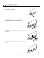
9-2 Installing the Option
Install the option as shown below. The installation procedure is the same for all the options.
1. Disconnect the AC adapter.
2. Remove the two screws and pull out the RS-232C board
provided as standard as shown in the illustration.
3. Insert the option board, along the guides on the left and
right sides.
4. Using the two screws removed in step 2, fasten the option
board.
18
10 BCD OUTPUT (AD-8922A-01)
Outputs the weighing data received from the weighing instrument in BCD format, along with the polarity
(+/-) and the data status (stable/unstable and over/under).
Using the STROBE signal, the data can be read easily. The AD-8922A-01 can set the input terminal
function to either the BUSY or the RE-ZERO input function by selecting that function. When set to the
RE-ZERO input function, the AD-8922A transmits the RE-ZERO command to the weighing instrument,
setting the weighing value to zero. BUSY input enables the data to be held or prevents data refreshing
during the reading operation.
The logic of data, status and strobe can be switched in the function setting.
Note: When the AD-8922A-01 is installed, the RS-232C serial interface can not be used.
When connected to the AD-4212C, the both instruments can share power.
For details about the RE-ZERO function of the applicable weighing instruments, refer to
RE-ZERO of Table 2 in "1-2 Applicable Instruments".
10-1 BCD Output Specifications
Accessories
I/O plug applicable to the BCD output port
1 pc.
Instruction manual
1 copy
Cable to connect to a weighing instrument (Length: Approx. 2 m) 1 pc.
D-Sub 25-pin to DIN 7-pin (AX-KO577A-200)
Note: A substitute cable may be provided as specified when ordering the AD-8922A.
D-Sub 9-pin to DIN 7-pin (AX-KO1786-200)
DIN 7-pin to DIN 7-pin (AX-KO507-W200)
A round waterproof 12-pin to DIN 7-pin (AX-KO3705-500)
The communications cable provided for the AD-4212C (5m)
Note: When the AD-8922A-01 is installed, the communications cable provided with the
AD-8922A will not be used.
Panel view
AD8922A BCD OUT
O P -01
BALANCE/SCALE
BCD output port (BCD-OUT)
19
Plug (Provided)
Part name
Over mold cover
Plug unit (Soldered type)
Product number
DX30M-50-CV
DX40M-50P
Manufacturer
Hirose Electric
Note: The products above are subject to be replaced with the equivalent.
Cable
Wire size
Core configuration
O.D. of insulator
AWG #28
7/0.127
0.58
Pin assignments and I/O logic
Output pin assignments
Pin No.
Signal
26
1
27
2
100
28
4
29
8
39
1
40
2
101
41
4
42
8
12
1
13
2
102
14
4
15
8
16
1
17
2
103
Data
18
4
19
8
20
1
21
2
104
22
4
23
8
46
1
47
2
105
48
4
49
8
24
1
25
2
106
30
4
31
8
32
1
33
2
107
34
4
35
8
Polarity
50
45
Stability
Status
44
Over
Strobe
43
Output signal GND
1
Input pin assignments
Pin No
Signal
BUSY/RE-ZERO
7
Input signal GND
3
-The pins, which are not specified, have no connection.
Output logic
Output
Factory settings
Data
1
ON
Polarity
Positive or zero
ON
Stability
Stabilization indicator ON
ON
Over
e, -e
ON
- All output, open collector; withstand voltage 30 V; no
pull-up resistor; low-level output current 48 mA
- Output logic of data, status, and strobe can be
switched individually in the function table bcd.
FG Use a shielded cable.
Housing (Cable shield)
(LS06)
BCD signals
Output signal GND
Input logic
Input
Balance
interior
Output pins
BCD signals
(Data from 100-1 to 107-8, Polarity,
Stability, OVER, Status, Strobe)
Pin 1
BCD signal ground
Data will be held during ON (when
connected to input signal GND).
RE-ZERO will be performed with ON
RE-ZERO
(when connected to input signal GND).
- All input, no voltage contact or open collector
(connected to 5 V internally)
- BUSY and RE-ZERO use same input terminal, set it
by the function.
BUSY
20
5V
FG
22kΩ
BUSY/
820Ω RE-ZERO
Use a shielded cable.
Housing (Cable shield)
(1) When a switch is used
5 pin
Input signal GND
(2) When a photocoupler is used
5 (Input terminal)
5 pin
CPU
input
terminal
Input signal GND
3
Input signal GND
(3) When a transistor is used
Balance interior
5 pin
Input signal GND
(Upon switch-ON, make the voltage
between the input terminal and the
input signal GND terminal 0.2V or less)
Output example
Display
BCD output
The example above is when the output logic has
been set at the factory.
The decimal point information will not be output.
Pin No.
26
27
28
29
39
40
41
42
12
13
14
15
16
17
18
19
20
21
22
23
46
47
48
49
24
25
30
31
32
33
34
35
50
45
44
Output pin assignments
Signal
1
2
0
10
4
8
1
2
1
10
4
8
1
2
2
10
4
8
1
2
3
10
4
8
1
2
4
10
4
8
1
2
5
10
4
8
1
2
6
10
4
8
1
2
107
4
8
Polarity
Stability
Over
Output
1
0
0
1
1
1
1
0
1
0
1
0
1
1
0
0
1
0
0
0
0
0
0
0
0
0
0
0
0
0
0
0
1
1
0
0:OFF
1:ON
21
I/O timing chart
After RE-ZERO
Receive data ON
OFF
(RS-232C)
BCD output
1
0
Tstr
STROBE
BUSY*
RE-ZERO*
Tstr
ON
OFF
ON
OFF
ON
OFF
100msec
The factory setting of Tstr (Strobe pulse width) is approx. 10 ms. It can be changed to approx. 20 ms or
approx. 50 ms in the function setting of "5trt".
* -“BUSY/RE-ZERO input ON” is the condition that BUSY is connected to input signal GND (Pin 3).
- The AD-8922A-01 can select either the BUSY input or the RE-ZERO input by setting the function.
When keeping the on state for 100msec, the weighing instruments keep the re-zero state.
22
RS-232C (BALANCE/SCALE)
Transmission system
Transmission form
Data format
:
:
:
EIA RS-232C
Asynchronous, bi-directional, half duplex
Baud rate
: 600, 1200, 2400, 4800, 9600, 19200bps
Data bits
: 7 or 8 bits
Parity
: Even, Odd (Data bits 7 bits)
None
(Data bits 8 bits)
Stop bit
: 1 or 2 bits
Code
: ASCII
Terminator
: <CR> or <CR><LF>
Circuit
TXD
SG
4
1
6
2
RXD
DIN 8-pin
AD-8922A interior
5
3
8
7
To a weighing instrument
Pin assignment(BALANCE/SCALE)
Pin No. Signal name Direction
Description
1
(Vs)
Internally used
⎯
2
TXD
Output
Transmit data
3
RXD
Input
Receive data
4
⎯
⎯
⎯
5
SG
Signal ground
⎯
6
(Va)
Internally used
⎯
7
⎯
⎯
⎯
8
⎯
⎯
⎯
When making the cable yourself, do not connect to the
internally used terminals.
23
10-2 Setting of the Decimal Point Position
The AD-8922A can set the display digit and the BCD output digit by setting dpp of the function.
When setting the decimal point position, the BCD output digit does not change if changing the minimum
display digit by pressing the SAMPLE key.
Example 1)When not setting the decimal point position(dpp -)[Factory setting]
(Key operation)
Balance display
AD-8922A display
BCD output
00012345
00123456
* When changing the minimum display digit by pressing SAMPLE key, the BCD shifts the output left and
adds the last digit.
Example 2)When setting the decimal point at the third digit position.(dpp 3)
(Key operation)
Balance display
AD-8922A display
BCD output
00123450
00123456
* When changing the minimum display digit by pressing SAMPLE key, the BCD output does not change
the number of digits.
24
11 COMPARATOR OUTPUT (AD-8922A-04)
The weighing data is compared with the upper and lower limit values and the results of the comparison are
contact-output in three levels of HI OK LO . The upper and lower limit values are set in the function setting.
Whether or not to sound the buzzer according to the results can be selected.
Note: When the AD-8922A-04 is installed, the pin assignment (DIN 8-pin), of the RS-232C serial
interface, to connect an external device, will be changed.
11-1 Comparator Output Specifications
Accessories
DIN connector (Plug)
1 pc.
Instruction manual
1 copy
Panel view
COMP.OUT
AD8922A BALANCE
OP- 0 4 /SCALE
Comparator output (COMP.OUT)
Maximum contact voltage:
100 VDC
Maximum contact current:
100 mA DC
Maximum contact resistance: 20 Ω
Comparator output judgement conditions (when upper limit value≥lower limit value):
Weighing data>upper limit value:
Activates the HI comparator output.
Upper limit value≥weighing data≥lower limit value: Activates the OK comparator output.
Weighing data<lower limit value:
Activates the LO comparator output.
Reference value setting:
Input the upper and lower limit values digitally.
Contact output:
Select whether or not to compare, using “Cp” of the function setting.
Buzzer:
Select whether or not to sound the buzzer, using “bep” of the function
setting.
25
RS-232C
Transmission system
Transmission form
Data format
:
:
:
EIA RS-232C
Asynchronous, bi-directional, half duplex
Baud rate
: 600, 1200, 2400, 4800, 9600, 19200 bps
Data bits
: 7 bits or 8 bits
Parity bit
: EVEN, ODD
(Data bits 7 bits)
NONE
(Data bits 8 bits)
Stop bits
: 1 bit or 2 bits
Code
: ASCII
Terminator
: <CR> or <CR><LF>
Circuit
COM
HI
SG
OK
DSR
SG
RXD
OK
AD-8922A interior
LO
5
4
9
3
8
2
7
LO
1
6
Inch screw thread
(#4-40UNC)
To a weighing instrument
4
1
6
2
8
TXD
TXD
RXD
HI
AD-8922 A interior
5
3
7
To an external device such as
a personal computer or a printer
Connection to the weighing instrument
Connection to an external device
D-Sub 9-pin (BALANCE/SCALE)
Pin
Signal
Direction
Description
No.
name
1
⎯
⎯
N.C.
2
RXD
Input
Receive data
3
TXD
Output Transmit data
4
⎯
⎯
N.C.
5
SG
⎯
Signal ground
6
DSR
Input
Data set ready
7
RTS
Output Request to send
8
⎯
⎯
N.C.
9
⎯
⎯
N.C.
DIN 8-pin (COMP.OUT)
Pin Signal
Description
No. name
1
HI
HI contact-output
2
COM COM contact-output
3
TXD Transmit data (RS-232C output)
4
LO
LO contact-output
5
SG
Signal ground
6
OK
OK contact-output
7
DSR Data set ready (RS-232C output)
8
RXD Receive data (RS-232C output)
(AD-8922A is a DTE. Connects to a DCE
such as a weighing instrument using a
straight through cable.)
26
11-2 Using the Comparator Output
To use the comparator output, perform the following four steps.
1. Connect the peripheral to the AD-8922A-04 DIN connector.
2. Set the “Comparator (Cp fnc)” of the AD-8922A function setting. For details, see “4. FUNCTION
SETTINGS”.
3. Set the upper and lower limit values. For details, see “11-3 Setting the Upper and Lower Limit
values”.
4. When the weighing data is received, the comparison results will be output.
When the weighing data is equal to or less than the upper limit value, and equal to or greater than
the lower limit value, the OK comparator will be output.
Comparator output
LO
OK
HI
Weighing data>upper limit
Open
Open
Short
Upper limit ≥weighing data≥lower limit
Open
Short
Open
Weighing data<lower limit
Short
Open
Open
Whether or not to sound the buzzer when the contact output is shorted
can be set in the “Buzzer mode (bep) of the “Comparator (Cp fnc)”.
Note: When setting the upper and lower limit values, make sure that the upper limit value is
greater than the lower limit value.
Function setting
The function setting "Cp fnc” is available only when the AD-8922A-04 is installed.
Parameter
Description
Class
Item
No
comparison
0
Cp
Comparison, excluding "near zero" when the value is
Comparator
1
stable or overloaded
mode
Comparison, including "near zero" when the value is
2
stable or overloaded
Continuous comparison, excluding "near zero"
3
Continuous comparison, including "near zero"
4
Cp fnc
Contact-outputs the second header information of the data
Comparator
5
received. (Applicable to AD-4212A, GP and GX-K)
OFF
0
Selects whether or not to sound the
bep
buzzer when LO.
ON
1
LO buzzer
OFF
0
Selects whether or not to sound the
bepbuzzer when OK.
ON
1
OK buzzer
OFF
0
Selects whether or not to sound the
bep
buzzer when HI.
ON
HI buzzer
1
Factory setting
Note: “Near zero” indicates the amount of ten digits (Digit = the smallest displayable weighing
value).
27
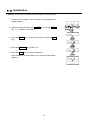
11-3 Setting the Upper and Lower Limit Values
Up to 10 set of upper and lower limit values can be stored.
Using the stored upper and lower limit values, comparison can be performed easily. To recall the
stored values, press and hold the ON:OFF key and press the MODE key.
11-3-1 Storing the upper and lower limit values
To store new upper and lower limit values, recall the stored data ("C01" to "C10") and change them.
1. While pressing and holding the ON:OFF key, press the RE-ZERO key to enter the confirmation
mode. The upper limit value data (Comparator number and the upper limit mass (blinking)) of the
comparator number that was selected last.
Displaying example
2. Select the comparator number using the following keys.
RE-ZERO key
MODE key
To increase the comparator number by 1.
To decrease the comparator number by 1.
Each time the key is pressed, the upper limit value and the lower limit value of the comparator
number selected is displayed alternately. (C01 HI ⇔ C01 LO ⇔ C02 HI ⇔ C02 LO ⇔…)
3. Press the SAMPLE key to go to the storing mode to change the stored values.
Digital input mode
SAMPLE key
To select the digit to change
the value.
RE-ZERO key
To change the value of the
digit selected.
MODE key
To move the decimal point
position to the right by 1
digit.
ON:OFF key (press and hold) MODE key
To switch the polarity.
PRINT key
To store the new setting and
return to step 2.
CAL key
To cancel the new setting
and return to step 2.
4. Press the CAL key to return to the weighing data
display.
28
11-3-2 Recalling the upper and lower limit values
The procedure below describes an easy way to recall the upper and lower limit values to be used for
weighing.
1 While pressing and holding the ON:OFF key, press the MODE key to enter the selection mode.
2 The upper limit value last selected with its comparator number appears.
3. Select the comparator number using the following keys.
RE-ZERO key
MODE key
To increase the comparator number by 1.
To decrease the comparator number by 1.
Each time the key is pressed, the upper limit value and the lower limit value of the comparator
number selected is displayed alternately. (C01 HI ⇔ C01 LO ⇔ C02 HI ⇔ C02 LO ⇔…)
Only the stored comparator numbers are displayed.
4 Press the PRINT key to confirm the selection and return to the weighing data display with the
selected upper and lower limit values ready for use (In the example shown below, the values of
"C08". )
Note: When no operation is performed in step 4 (after a few seconds of inactivity), the AD-8922A
selects the value currently displayed and returns to the weighing data display
automatically.
To cancel the operation, press the CAL key.
29
12 CURRENT LOOP INPUT (AD-8922A-05)
Can receive the current loop output from the weighing instrument. The data received can be output to an
external device such as a personal computer and a printer, using the RS-232C serial interface. The
weighing instrument can not be operated using the AD-8922A keys.
Note: When AD-8922A-05 is installed, the pin assignment (DIN 8-pin) of the RS-232C serial
interface, to connect an external device, will be changed.
Note: The AD-4212C does not have current loop output. Therefore, this option can not be used.
12-1 Current Loop Input Specifications
Accessories
Cable to connect to a weighing instrument (AX-KO1786-200: Length: Approx.2 m )
DIN 7-pin to D-Sub 9-pin
Instruction manual
1 copy
Note: When the AD-8922A-05 is installed, the communications cable provided with the AD-8922A
as standard will not be used.
Panel view
AD8922A CURRENT
OP- 05 LOOP
PC/PRINTER
Current loop input / PC/PRINTER output
Transmission system
:
Transmission form
Data format
:
:
Input: 20 mA current loop (Active)
D-Sub 9-pin (Current loop)
Output: EIA RS-232C DIN 8-pin (PC/PRINTER)
Asynchronous, uni-directional
Baud rate
: 600, 1200, 2400, 4800, 9600, 19200 bps
Data bits
: 7 bits or 8 bits
Parity bit
: EVEN, ODD
(Data bits 7 bits)
NONE
(Data bits 8 bits)
Stop bits
: 1 bit or 2 bits
Code
: ASCII
Note: When a baud rate of 4800 bps or higher is used, communication may not be performed
properly.
30
Circuit
5V
C.L
C.L
DSR
TXD
3.3kΩ
SG
AD-8922A interior
4
5
4
9
3
8
2
7
1
1
6
Inch screw thread
(#4-40UNC)
To a weighing instrument
6
2
AD-8922A interior
5
3
8
7
To an external device such as
a personal computer or a printer
Connection to the weighing instrument
Connection to an external device
D-Sub 9-pin (Current loop)
Pin Signal
Description
No. name
1
⎯
N.C.
2
C.L
Current loop
3
⎯
N.C.
4
⎯
N.C.
5
C.L
Current loop
6
⎯
N.C.
7
⎯
N.C.
8
⎯
N.C.
9
⎯
N.C.
DIN 8-pin (PC/PRINTER)
Pin Signal
Description
No. name
1
⎯
N.C.
2
⎯
N.C.
3
TXD Transmit data (RS-232C output)
4
⎯
N.C.
5
SG
Signal ground
6
⎯
N.C.
7
DSR Data set ready (RS-232C output)
8
⎯
N.C.
31
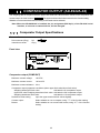
13 ANALOG OUTPUT (AD-8922A-06)
Converts the specified digits of the weighing data received from the weighing instrument to voltage and
outputs. The output voltage can be selected from "0 to 1 V" and "0.2 to 1 V".
Note: When the AD-8922A-06 is installed, the pin assignment (DIN 8-pin), of the RS-232C serial
interface, to connect an external device, will be changed.
13-1 Analog Output Specifications
Accessories
DIN connector (Plug)
1 pc.
Screwdriver
1 pc.
Instruction manual
1 copy
Panel view
AD8922A BALANCE
O P - 06 /SCALE
ANALOG OUT
0V /0.2V
ZERO SPAN
Analog output
Output impedance
100 Ω or less
Linearity
0.3% or less
Output range
0 V-1 V (With the slide switch set to “0V~“)
0.2 V-1 V (With the slide switch set to “0.2V~“)
RS-232C
Transmission system
Transmission form
Data format
:
:
:
EIA RS-232C
Asynchronous, bi-directional, half duplex
Baud rate
: 600, 1200, 2400, 4800, 9600, 19200 bps
Data bits
: 7 bits or 8 bits
Parity bit
: EVEN, ODD
(Data bits 7 bits)
NONE
(Data bits 8 bits)
Stop bits
: 1 bit or 2 bits
Code
: ASCII
Terminator
: <CR> or <CR><LF>
32
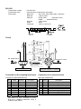
AD-8922A interior
4
5
4
9
3
8
2
7
SG
10 Ω
RXD
Analog
GND
Analog
output
TXD
RXD
DSR
SG
TXD
Circuit
1
1
6
Inch screw thread
(#4-40UNC)
6
2
5
AD-8922A interior
3
8
7
To an external device such as
a personal computer or a printer
To a weighing instrument
Connection to the weighing instrument
Connection to an external device
D-Sub 9-pin (BALANCE/SCALE)
Signal
Pin
Direction
Description
No.
name
1
⎯
⎯
N.C.
2
RXD
Input
Receive data
3
TXD
Output Transmit data
4
⎯
⎯
N.C.
5
SG
⎯
Signal ground
6
DSR
Input
Data set ready
7
⎯
⎯
N.C.
8
⎯
⎯
N.C.
9
⎯
⎯
N.C.
DIN 8-pin (ANALOG.OUT)
Pin
Signal
Direction
No.
name
1
⎯
⎯
2
AG
⎯
3
TXD
Output
4
⎯
⎯
5
SG
⎯
6
DSR
Output
7
AOUT
Output
8
RXD
Input
(AD-8922A is a DTE. Connects to a DCE
such as a weighing instrument using a
straight through cable.)
33
Description
N.C.
Analog ground
Transmit data
N.C.
Signal ground
Data set ready
Analog output
Receive data
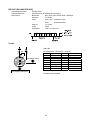
13-2 Function setting
The function setting " aout” is available only when the AD-8922A-06 is installed.
Parameter
Description
Class
Item
Converts
the consecutive 2 digits,
an
2-digt
output
with
the
digit
selected in 5el as the
0
Analog output
least,
to
voltage
and outputs.
mode
Converts the consecutive 3 digits,
3-digt output
with the digit selected in 5el as the
1
aout
least, to voltage and outputs.
Analog
Selects the first digit as the least.
0
5el
output
Selects the second digit as the least.
1
Analog output
digit selection
Selects the third digit as the least.
2
Selects the fourth digit as the least.
3
Selects the fifth digit as the least.
4
Selects the sixth digit as the least.
5
Factory setting
Setting example
Notes
The invisible high-order digits are regarded as zero.
34
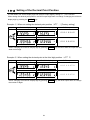
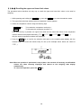
13-3 Switching Output Voltage
The output voltage can be switched using the slide switch on the option panel. “0V~” has been set at
factory before shipment.
“0V~” (0-1 V):
At zero=0.000 V
At full scale=1.000 V
“0.2~” (0.2-1 V): At zero =0.200 V
At full scale=1.000 V
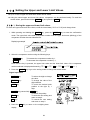
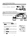
13-4 Output Voltage Fine Adjustment
The output voltage has been adjusted at the factory before
shipment.
Using the ZERO and SPAN fine-adjustment knobs and a
voltmeter, output voltage can be fine adjusted.
13-4-1 Fine-adjustment procedure
1. While pressing and holding the ON:OFF key, press the
RE-ZERO key. At this time, the output voltage will be at
zero.
2. Turn the ZERO knob so that the voltmeter indicates 0.000 V
when the slide switch is set to “0V~”; 0.200 V when the
slide switch is set to “0.2V~”.
3. Press the RE-ZERO key. At this time, a voltage of 1 V is
generated. Turn the SPAN knob so that the voltmeter
indicates 1.000 V.
4. Press the RE-ZERO key again to return to step 2. Repeat
steps 2 and 3 until the correct output voltage is obtained.
5. Press the CAL key to return to the weighing data display.
35
13-5 Fixed Output Voltage
The output voltage is fixed under the following conditions:
1. While the weighing data is not displayed
(e.g., the bar display, function setting operation)
:0 V (or 0.2 V)
2. When “-e” (Weighing pan error) is being displayed:
:0 V (or 0.2 V)
3. When “e” (Overload error) is being displayed:
:1V
36
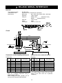
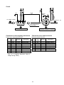
14 ACCESSORIES (CABLE LIST)
1. Cable to connect the AD-8922A, AD-8922A-01, AD-8922A-04, or AD-8922A-06 and the weighing
instrument
Table 8 Applicable weighing instruments and what is required
Weighing
instrument
AD-4212C
GX, GF, GX-K,
GF-K, GP, FP,
AD-4212A/B, GR,
HR
EK-i, EW-i, FC-i,
FC-Si, GH, HR-i,
FZ-i, FX-i
EK-G, EK-H,
ET-W, EW-G
HV-G, HV-WP,
HW-G, HW-WP
Option for the
instrument
None
(D-Sub 9-pin)
What is required to connect to
a weighing instrument
Communications cable (Length 2 m)
・ AD-8922A standard
・ To connect AD-8922A-04 To connect AD-8922A-01
or AD-8922A-06
Cable provided for
AD-4212C (5m)
AX-KO3705-500 (5m)
AX-KO3590-500
None
(D-Sub 25-pin)
AX-KO1710-200
AX-KO577A-200
None
(D-Sub 9-pin)
AX-KO2466-200
AX-KO1786-200
OP-03
AX-KO1710-200
AX-KO577A-200
(D-Sub 25-pin)
None
AX-KO1786-200
AX-KO507A-200
(DIN 7-pin)
OP-03
FG
AX-KO1786-200
AX-KO507-W200
(DIN 7-pin)
OP-03
FS, FS-KL
AX-KO1786-200
AX-KO507-W200
(DIN 8-pin)
OP-23
FG-L, FG-M
AX-KO1786-200
AX-KO507-W200
(DIN 8-pin)
Note: A substitute communications cable may be provided as specified when ordering the
AD-8922A or AD-8922A-01.
2. Cable to connect the AD-8922A-05 and the weighing instrument: AX-KO1786-200 (AD-8922A-05
accessory)
3. Cable to connect the AD-8922A or AD-8922A-05 and an external device
When connecting to a personal computer: AX-KO1786-200
When connecting to the compact printer AD-8121B: AX-KO462-200
37
38
39
40