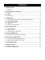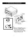
1
AD-8923-BCD
Remote Controller
(BCD)
INSTRUCTION MANUAL
1WMPD4002137
© 2010 A&D Company, Limited. All rights reserved.
No part of this publication may be reproduced, transmitted, transcribed, or translated
into any language in any form by any means without the written permission of A&D
Company, Limited.
The contents of this manual and the specifications of the instrument covered by this
manual are subject to change for improvement without notice.
.
CONTENTS
1. INTRODUCTION ....................................................................................... 2
1.1. Features ............................................................................................... 2
2. DESCRIPTION OF EACH PART .............................................................. 3
2.1. Display ................................................................................................. 4
2.2. Keys ..................................................................................................... 4
2.3. Connectors........................................................................................... 4
3. CONNECTION .......................................................................................... 5
3.1.
3.2.
3.3.
3.4.
3.5.
Setting the weighing instrument and the AD-8923-BCD ...................... 5
Connecting the cables.......................................................................... 5
Turning the power on ........................................................................... 6
Operation ............................................................................................. 8
Calibrating the AD-4212C .................................................................... 8
4. FUNCTION SETTING ............................................................................. 10
4.1. Display and keys .................................................................................11
4.2. Function table......................................................................................11
4.3. Initializing the AD-8923-BCD.............................................................. 12
5. RS-232C CONNECTOR.......................................................................... 13
5.1. RS-232C serial interface specifications.............................................. 13
6. BCD OUTPUT CONNECTOR ................................................................. 14
6.1. Connector Pin No and Specifications ................................................. 14
6.2. Fixing of the Decimal Point Position................................................... 16
7. TROUBLESHOOTING ............................................................................ 17
8. SPECIFICATIONS................................................................................... 18
9. EXTERNAL DIMENSIONS...................................................................... 18
1
1. INTRODUCTION
This manual describes how the AD-8923-BCD remote controller works and
how to get the most out of it in terms of performance.
Read this manual thoroughly before using the AD-8923-BCD and keep it at
hand for future reference.
1.1. Features
Connecting the AD-8923-BCD remote controller and the AD-4212C series
production weighing unit will enable transmission of the weight data to a
PLC using BCD.
z Displays the weight data transmitted from the weighing instrument.
z Can change the weighing speed of the AD-4212C, calibrate the
AD-4212C using an external calibration weight and share the power
supply with the AD-4212C.
Note
When the AD-4212C is used as the weighing instrument,
connecting power to either the AD-8923-BCD or the AD-4212C will
supply power to both devices. Refer to “3.3. Turning the power
on.”
z When connecting the AD-8923-BCD output, refer to “6. BCD OUTPUT
CONNECTOR”
2
2. DESCRIPTION OF EACH PART
Display
AC adapter
input jack
DC input terminal
Keys
BCD connector
Accessories
FG terminal
BCD plug 1 pc.
RS-232C connector
(D-Sub 9-pin)
See the note
below.
Rear View
.
Note
When the AD-8923-BCD is to be
built into a weighing system, be
sure to ground the FG terminal.
AC adapter 1 pc. AD adapter
ID label
Please confirm that the AC adapter
type is correct for your local
voltage and receptacle type.
3
2.1. Display
AD-8923
REMOTE CONTROLLER
RESPONSE
SLOW
STABLE FAST
MID.
Turns on while the AD-4212C
is in the standby mode.
STABLE indicator Weighing
Unit indicator
speed
indicators
ON:OFF
CAL
SAMPLE
PRINT
MODE
RE-ZERO
z Displays the weight data received. When the unit is “g” (gram), the unit
indicator turns on.
z When the weight value is stable (the header of the weight data received is
“ST”), the STABLE indicator turns on.
z If the AD-8923-BCD does not receive the weight data for two seconds or
more,
- - - - - is displayed (Bar display).
z Displays the AD-4212C weighing speed that is currently set, by turning on
the corresponding indicator.
2.2. Keys
z Operates the weighing instrument. For details, refer to “3.4. Operation”.
z To enter the function setting of the AD-8923-BCD, press the CAL key
while holding down the ON:OFF key. For details, refer to “4. FUNCTION
SETTING”.)
2.3. Connectors
z RS-232C connector ...... D-Sub 9-pin (male)
Used to connect to the AD-4212C weighing unit. For details, refer to “5.
RS-232C CONNECTOR”.
z BCD connector ............. Half pitch 50-pin (female)
Used for connecting the AD-8923-BCD to another instrument. For details,
refer to “6. BCD OUTPUT CONNECTOR”.
z DC input terminal (24 DCV) / AC adapter input jack
Either power supply can be used. For details, refer to “3.3. Turing the
power on”.
4
3. CONNECTION
3.1. Setting the weighing instrument and the AD-8923-BCD
Set the following items so that the weighing instrument and the
AD-8923-BCD have the same value for each item.
Item
Weighing instrument
AD-8923-BCD
Baud rate
600, 1200, 2400*, 4800, 9600, 19200 bps
Data bits, parity
7 bits EVEN*
Stop bit
1 bit*
Terminator
<CR><LF>*
Data format
A&D standard format
−
Communication control
No RTS/CTS control
−
Data output mode
Stream mode
−
* Factory setting for the AD-8923-BCD. The factory setting for the weighing instrument is
the same unless otherwise specified.
3.2. Connecting the cables
Connect the cables using the connectors located on the rear of the
AD-8923-BCD.
Connection example to the AD-4212C and a PLC
RS-232C connector (D-Sub 9-pin)
AD-8923-BCD
BCD connector (Half pitch 50-pin)
Connect to the power supply
Refer to “3.3. Turning the power on”.
AD-4212C
Ground
Ground
BCD signals
RS-232C cable provided
with the AD-4212C
PLC
Note
Be sure to ground the AD-4212C and the AD-8923-BCD.
5
3.3. Turning the power on
As a power supply, an external 24-VDC power supply (24 VDC±10% /
700mA) or a 12-VDC AC adapter can be used.
Note
When the AD-4212C is used, connecting power to either the
AD-8923-BCD or the AD-4212C will supply power to both devices.
So, instead of the AD-8923-BCD, using the AC adapter on the
AD-4212C will supply power to the AD-8923-BCD.
If the power is connected to both, no problems occur because the
power to be used is selected automatically.
When the external 24-VDC power supply is used
Connect an external 24-VDC power supply to the DC input terminal located
on the rear of the AD-8923-BCD.
Precautions on using the external power supply
CAUTION
z Use a power supply within the rated voltage range (24 VDC±10%).
Never use a power supply with a voltage exceeding the rated range.
• It may cause damage or heat buildup.
• The AD-8923-BCD may not function properly.
z Ground the FG terminal of the switching power supply used.
• To avoid electrical shock and increase the system safety.
• To increase the resistance against noises.
z Do not share the power line with other devices.
• Strong noises introduced from other devices may cause damage to the
AD-8923-BCD.
• Inrush current from other devices may cause the AD-8923-BCD not to start
up properly.
• Circuit configuration of the AD-8923-BCD may affect other devices to
prevent them from functioning properly.
z Select a switching power supply with a capacity of approximately 700mA
for each AD-8923-BCD. Note that the AD-8923-BCD may not start up with
a capacity less than 700mA.
• If the power supply capacity is not sufficient, the AD-8923-BCD may not
function properly.
6
z Be sure to add a noise filter on the front end of the switching power supply
and ground the FG terminal.
• This will increase the resistance against noises.
z Be sure to ground the FG terminal of the AD-8923-BCD and the
AD-4212C.
• This will increase the resistance against noises.
Cable connection
CAUTION
Before inserting the power line, make sure that the power to the
AD-8923-BCD is turned off.
DC input terminal
AD-8923-BCD rear
(1) Inserting the power line
Press down the release button on the
DC input terminal using a screwdriver
and insert the power line.
The recommended stripping length
for the power line is 10 mm.
Release button
Power line
Screwdriver
Applicable wire range
• Single wire: φ1.0 mm (AWG 26) to φ1.2 mm (AWG 16)
• Twisted wire: 0.3 mm2 (AWG 22) to 0.75 mm2 (AWG 20)
Individual wire diameter φ0.18 mm or greater
(2) Securing or removing the power line
To secure the power line, return the release button to the initial position
using the screwdriver. The power line will be locked.
To remove the power line, press the release button again using the
screwdriver, unlocking the power line.
AC adapter input jack
When the AC adapter is used
Insert the AC adapter plug into the AC
adapter input jack located on the rear
of the AD-8923-BCD and insert the AC
adapter into an electrical outlet.
DC input terminal
AC adapter plug
AD-8923-BCD rear
7
3.4. Operation
z Displays the data transmitted by the weighing instrument connected.
z The AD-8923-BCD key functions when connected to a weighing
instrument are listed below: (e.g. when the AD-4212C is connected)
Model
Keys of the AD-8923-BCD
ON:OFF
Switches
between the
weighing
AD-4212C
mode and
the standby
mode.
CAL
Enters the
calibration
mode
using a
weight.
SAMPLE
PRINT
Switches the Used for the
minimum
function
display.
setting mode
and
calibration
mode.
MODE
RE-ZERO
Switches Sets the
the
display to
weighing zero.
speed.
3.5. Calibrating the AD-4212C
The following is the calibration procedure when the AD-4212C is connected.
(A calibration weight is used.)
Caution
z Do not allow vibration, drafts or temperature change to affect the
AD-4212C during calibration.
Caution on using an external calibration weight
z The accuracy of the weight can influence the accuracy of weighing.
Select an appropriate weight as listed below.
A calibration weight of 200 g (conforming to OIML, Class E2 or equivalent)
is provided with the AD-4212C as a standard accessory.
Weighing instrument
Usable calibration weight
AD-4212C-300
50g, 100g, 200 g, 300g
AD-4212C-600
50g, 100g, 200 g, 300g, 400 g, 500 g, 600 g
AD-4212C-3000
50g, 100g, 200 g, 300g, 400 g, 500 g, 1000 g, 2000g, 3000g
AD-4212C-6000
200 g, 500 g, 1000 g, 2000g, 3000g, 4000 g, 5000 g, 6000 g
The calibration weight in bold type: factory setting
Display
z This indicator means “the AD-4212C is measuring
calibration data”. Do not allow vibration, drafts or
other external disturbances to affect AD-4212C
while this indicator is displayed.
8
Calibration procedure
Calibrates the AD-4212C using the calibration weight.
Operation
1. Warm up the AD-4212C for 30 minutes or more with
nothing on the pan.
RESPONSE
2. Press the CAL key.
Cal 0
is displayed.
z If you want to cancel calibration, press the CAL
key. The display will return to the weighing mode.
z If you want to change the calibration mass value,
press the SAMPLE key.
Press the RE-ZERO key to select the mass value,
and press the PRINT key to store it. Cal 0 is
displayed.
3. Confirm that there is nothing on the pan and press
the PRINT key. The AD-4212C measures the zero
point. Do not allow vibration or drafts to affect the
AD-4212C.
The calibration weight value is displayed.
MID. SLOW
STABLE FAST
Press
CAL
RESPONSE
MID. SLOW
STABLE FAST
Press
PRINT
RESPONSE
STABLE FAST
MID. SLOW
RESPONSE
STABLE FAST
MID. SLOW
4. Place a calibration weight, of the weight value Calibration
displayed, on the pan and press the PRINT key. weight
The AD-4212C measures the calibration weight.
Press
Do not allow vibration or drafts to affect the
AD-4212C.
5. end
pan.
is displayed. Remove the weight from the
6. The display will automatically return to the weighing
mode.
PRINT
RESPONSE
MID. SLOW
STABLE FAST
RESPONSE
STABLE FAST
7. Place the calibration weight on the pan and confirm
that calibration was performed correctly. If not,
check the ambient conditions such as drafts or
vibration, and repeat steps 2 through 7.
9
MID. SLOW
RESPONSE
STABLE FAST
MID. SLOW
4. FUNCTION SETTING
Function setting specifies the AD-8923-BCD performance. The parameters are
stored in non-volatile memory, and are maintained even if the power line or AC
adapter is removed.
The function setting menu consists of two layers. The first layer is the “Class”
and the second layer is the “Item”. Each item stores a parameter.
Press the SAMPLE key to select an item and press the RE-ZERO key to
change the parameter. Then, press the PRINT key to store the new
parameter.
Example
This example sets “Baud rate” to “9600 bps”.
START
While holding
down
press
Item
"Baud rate"
Parameter
"9600 bps"
Press twice
Item
Class
END
Note
The AD-8923-BCD may not function properly, depending on the
settings and operating environment. Check the settings and change
them as necessary.
10
4.1. Display and keys
The STABLE indicator turns on to indicate that the parameter displayed is
in effect.
Selects a class or item.
Changes the parameter.
When a class is displayed, moves to an item in the class.
When an item is displayed, stores the new parameter and displays the
next class.
When an item is displayed, cancels the new parameter and displays the
next class.
When a class is displayed, exits the function setting mode and
returns to the weighing mode.
4.2. Function table
Class
Item and Parameter
-
Not fixed
0
fnc
Environment
Display
dpp
Decimal point
position
5
5apl
Sample key
function
5if
Serial
interface
Fixed
bp5
Baud rate
Description
Displays the decimal point position
of the weight data received.
Fixes the decimal point at the set
digit. Even if the minimum display
is switched using the SAMPLE key,
the decimal point position does not
change. For details, refer to
“6.2.Fixing of the Decimal Point
Position”.
0
Disabled
Disables the SAMPLE key function.
1
Enabled
Enables the SAMPLE key function.
0
600 bps
1
1200 bps
2
2400 bps
3
4800 bps
4
9600 bps
5
19200 bps
Factory setting
11
Set the same value as that of the
weighing instrument to be
connected.
4.3. Initializing the AD-8923-BCD
Initialization restores the function settings of the AD-8923-BCD to factory
settings.
Operation
1 Turn the power on. - - - - mode display appears.
or weighing
While holding ON:OFF
down
2 While holding down the ON:OFF key, press
Press
the PRINT key.
Clr
is displayed.
PRINT
3 Press the PRINT key.
To cancel this operation, press the CAL key
Press
4 Press the RE-ZERO key to select “go”.
Press
RE-ZERO
5 Press the
initialization.
Press
PRINT
PRINT
key
After initialization, - - - - mode display appears.
to
perform
or weighing
.
12
PRINT
5. RS-232C CONNECTOR
The RS-232C cable provided with the AD-4212C can be connected directly.
5.1. RS-232C serial interface specifications
RS-232C
Transmission system : EIA RS-232C
Transmission form : Asynchronous, bi-directional, half duplex
Data format
: Baud rate : 600, 1200, 2400, 4800, 9600, 19200 bps
Data bits : 7 or 8 bits
Parity
: EVEN, ODD (Data bits 7 bits)
NONE (Data bits 8 bits)
Stop bits : 1 bit or 2 bits
Code
: ASCII
Terminator : <CR> or <CR><LF>
LSB
0
1
2
3
4
5
Data bits
RS-232C
1 -5V to -15V
0 +5V to +15V
MSB
6
Stop bit
Parity bit
Start bit
Circuit
Pin Signal Direction
No. name
1
(Vs)
−
(RTS) RXD
(DSR)
(Vs)
SG
(Va)
(CTS) TXD
Connection to the weighing instrument
D-Sub 9-pin
AD-8923-CC
interior
5
4
9
3
8
2
7
1
6
Inch screw
(#4-40UNC)
To the weighing instrument
Description
Used internally
2
RXD
Input
Receive data
3
TXD
Output
Transmit data
4
−
−
N.C.
5
SG
−
Signal ground
6
(DSR)
−
Used internally
7
(RTS)
−
Used internally
8
(CTS)
−
Used internally
9
(Va)
−
Used internally
(The AD-8923-BCD is a DTE device.
Connect to a DCE device such as the
AD-4212C, using a straight through
cable.)
Note
When the user prepares a cable, do not connect to the pins that
are used internally.
13
6. BCD OUTPUT CONNECTOR
Outputs the weighing data received from the weighing instrument in BCD
format, along with the polarity (+/-) and the data status (stable/unstable and
over (E display)).
Using the STROBE signal, the data can be read easily. BUSY input enables
the data to be held or prevents data refreshing during the reading operation.
Contact inputs are RE-ZERO and ON/OFF. They have same function as the
key switches on the front panel.
6.1. Connector Pin No and Specifications
I/O connector of the rear panel
25
50
Pin assignments and I/O logic
Output pin assignments
Signal
1
2
100
4
8
1
2
101
4
8
1
2
102
4
8
1
2
103
4
Data
8
1
2
104
4
8
1
2
105
4
8
1
2
106
4
8
1
2
107
4
8
Polarity
Status
Stability
Over
Controlling
43
Strobe
signals
1
Output signal GND
Housing Frame ground
Pin No.
26
27
28
29
39
40
41
42
12
13
14
15
16
17
18
19
20
21
22
23
46
47
48
49
24
25
30
31
32
33
34
35
50
45
44
1
Half pitch 50 pin
26
Input pin assignments
Pin No.
Signal
7
BUSY
9
RE-ZERO
Switch
5
ON/OFF
3
Input signal GND
11
Do not use
-The pins, which are not specified, have no connection.
(2, 4, 6, 8, 10, 36, 38 pin)
Output logic
Output logic (Factory settings)
Data
1
ON
Polarity
Positive or zero
ON
Stability
Stabilization indicator ON
ON
Over
e, -e
ON
Strobe
Changing data
ON*
Status
Weighing state
ON
* When changing OFF→ON, replaces the data.
- All output, open collector; withstand voltage 30 V; no
pull-up resistor; low-level output current 10 mA
FG Use a shielded cable.
Housing (Cable shield)
Output pins
BCD signals
7
0
(Data from 10 -1 to 10 -8, Polarity,
Stability, OVER, Status, Strobe)
Pin 1
Output signal GND
BCD
signals
Balance
interior
14
Input logic
Data will be held during ON (when
connected to input signal GND).
BUSY
Switch
Switch will be performed with ON (when
input
connected to input signal GND).
- All input, no voltage contact or open collector
(connected to 5 V internally)
(1)When a switch is used
5, 9, 7 pin
+5V
FG
FG
Housing (Cable shield)
Input terminal
4.7kΩ RE-ZERO, ON/OFF, BUSY
Input signal GND
3
Input signal GND
(2) When a photocoupler is used
5, 9, 7 pin
Input signal GND
(Upon switch-ON, make the voltage
between the input terminal and the
input signal GND terminal 0.2V or less)
Balance interior
Plug (Provided)
Part name
Product number
Manufacturer
Over mold cover
DX30M-50-CV
Hirose Electric
Plug unit (Soldered type)
DX40M-50P
Note: The products above are subject to be replaced with the equivalent.
Cable
Wire size
AWG #28
Core configuration
7/0.127
O.D. of insulator
0.58
Note: Use a shielded cable. Connect the shield to the connector case.
I/O timing chart
After RE-ZERO
Receive data ON
(RS-232C)
OFF
BCD output
1
0
STROBE
ON
OFF
BUSY*
ON
OFF
RE-ZERO*
ON
OFF
Tstr
Tstr
100msec
The factory setting of Tstr (Strobe pulse width) is approx. 10 msec. The BCD data
should be acquired approximately 5 msec after the strobe changes from ON to OFF.
* -“All input pins ON”, is the condition, where all input signals are connected to
GND (Pin 3).
- When inputting RE-ZERO for 100 msec, the weighing instrument
maintains the re-zero state.
15
6.2. Fixing of the Decimal Point Position
The AD-8923-BCD can set the display digit and the BCD output digit by
setting dpp of the function.
When fixing the decimal point position, the BCD output digit does not change
if changing the minimum display digit by pressing the SAMPLE key.
Example 1)When not fixing the decimal point position.(dpp -)
[Factory setting]
Key
AD-8923-BCD display
Balance output
S T , + 0 0 1 2 3 . 4 6 , g CR LF
RESPONSE
STABLE FAST
00012346
MID. SLOW
RESPONSE
STABLE FAST
BCD output
00123456
MID. SLOW
Note
: space 20h
When changing the minimum display digit by pressing SAMPLE
key, the BCD shifts the output left and adds the last digit.
Example 2)When fixing the decimal point at the third digit position.(dpp 3)
Key
Balance output
AD-8923-BCD display
S T , + 0 0 1 2 3 . 4 6 , g CR LF
RESPONSE
STABLE FAST
00123460
MID. SLOW
RESPONSE
STABLE FAST
BCD output
00123456
MID. SLOW
Note
: space 20h
When changing the minimum display digit by pressing SAMPLE
key, the BCD output does not change the number of digits.
16
7. TROUBLESHOOTING
Symptom
eerror 10
appears.
- - - - - - (Bar display)
remains and the weight
value is not displayed.
Description
Communication settings of the AD-8923-BCD do not match
with those of the weighing instrument.
Check the settings such as baud rate and parity and correct
them as necessary.
For details, refer to “3.1. Setting the weighing instrument and
the AD-8923-BCD”.
• Is the data output mode of the weighing instrument set to
“stream mode”?
In a mode other than “stream mode”, the weight values
are displayed only when they are transmitted.
• Check if the communication settings are correct.
• Check if the cables are the correct type and are not
damaged.
Electrical noise may cause this symptom.
The display flickers.
Ground the FG terminal located on the rear of the
AD-8923-BCD.
17
8. SPECIFICATIONS
Power supply
: External 24-VDC power supply (24 VDC±10% / 700mA)
or
AC adapter (Output: 12 VDC / 300mA)
Please confirm that the AC adapter type is correct for
your local voltage and receptacle type.
Transmission system
: RS-232C, BCD
Communications connector : D-Sub 9-pin (male) (RS-232C connector to the weighing
instrument)
Half pitch 50-pin (female) (BCD connector)
External dimensions
: 144 (W) X 110 (D) X 72 (H) mm
Mass
: Approx. 1.0 kg
Standard accessories
: BCD plug
1 pc.
9. EXTERNAL DIMENSIONS
67
10
(116)
110
100
137
144
+1
138 0
SAMPLE PRINT
RESPONSE
STABLE
FAST
MID.
CAL
72
ON:OFF
68+0.7
0
REMOTE CONTROLLER
AD-8923
Panel cutout dimensions
SLOW
MODE
RE-ZERO
BCD OUT
Panel cutout dimensions when
panel mounted
Unit: mm
18