1
Waterproof Digital Platform Scale
HV-15KV-WP
HV-60KV-WP
HV-200KV-WP
HW-10KV-WP
HW-60KV-WP
HW-100KV-WP
HW-200KV-WP
1WMPD4000211B
This is a hazard alert mark.
This mark informs you about the operation of the product.
Note
This manual is subject to change without notice at any time to improve the product.
No part of this manual may be photocopied, reproduced, or translated into another
language without the prior written consent of the A&D Company.
Product specifications are subject to change without any obligation on the part of the
manufacture.
Contents
1.
Compliance ........................................................................ 3
1.1.1.
1.1.2.
Compliance with FCC rules....................................................... 3
Classification of protection provided by enclosures .................. 3
2.
Outline and Features.......................................................... 4
3.
Unpacking .......................................................................... 5
3.1.
4.
Accessories and Options list ......................................................... 6
Caution............................................................................... 7
4.1.
4.2.
4.3.
5.
Precautions for Installing the Scale ............................................... 7
Precautions for Operating the Scale.............................................. 7
Precautions for Storing the Scale .................................................. 7
Installing the Scale ............................................................. 8
5.1.
5.2.
6.
Removing the pole ........................................................................ 9
Grounding the scale .................................................................... 11
Names.............................................................................. 12
6.1.
6.2.
7.
Display and Symbols................................................................... 13
Switches...................................................................................... 15
Basic Operation................................................................ 17
7.1.
7.2.
7.2.1.
7.2.2.
7.3.
7.4.
8.
Turing the Scale on/off and Weighing ......................................... 17
Tare (And Net Display)................................................................ 18
The Way of Tare Input by Weighing........................................ 18
The Way of Digital Input (Preset Tare).................................... 18
Weighing Range for the HV-WP series ....................................... 19
Mode Switch (Changing Unit and Mode)..................................... 20
Counting Mode................................................................. 22
8.1.
8.2.
9.
Storing a Unit Mass ..................................................................... 22
Counting the number of articles .................................................. 23
Percentage Mode............................................................. 24
9.1.
9.2.
10.
10.1.
10.2.
11.
11.1.
11.2.
12.
Storing a 100% Mass .................................................................. 24
Reading percentage .................................................................... 25
Accumulation Function..................................................... 26
Preparation (Setting Parameters)................................................ 27
Operation and Performance (Examples) ..................................... 28
Upper/Lower Comparator Function .................................. 29
Preparation (Setting Parameters)................................................ 30
Operation and Performance (Examples) ..................................... 32
Full/Dribble Batch Function .............................................. 33
HV-WP/HW-WP Series
Page 1
12.1.
13.
Preparation (Setting Parameters)................................................ 35
Simple Batch Function ..................................................... 37
13.1.
13.2.
14.
Preparation (Setting Parameters)................................................ 38
Operation and Performance (Examples) ..................................... 39
Calibration (Adjusting the Scale) ...................................... 40
14.1.1.
The Gravity Acceleration Table............................................... 41
14.2.
The Complete Calibration Procedure .......................................... 42
14.2.1.
Gravity Acceleration Correction .............................................. 42
14.2.2.
Preparation ............................................................................. 42
14.2.3.
Calibration of the Zero Point ................................................... 43
14.2.4.
Span Calibration ..................................................................... 43
15.
The Function Table .......................................................... 44
15.1.
15.2.
16.
The Procedure for Setting Parameters........................................ 44
Parameter List ............................................................................. 45
RS-232C Serial Interface ................................................. 48
16.1.
Data Format ................................................................................ 49
16.2.
Stream Mode............................................................................... 51
16.2.1.
Preparation and Performance (Examples) .............................. 51
16.3.
Command mode.......................................................................... 52
16.3.1.
Command List ......................................................................... 52
16.3.2.
Example of Setting Parameters .............................................. 55
17.
Options............................................................................. 56
17.1.
17.2.
17.2.1.
17.3.
17.3.1.
17.3.2.
17.3.3.
17.4.
Extension cable (OP-02) ............................................................. 56
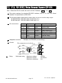
RS-232C/ Relay output/ Buzzer (OP-03)..................................... 57
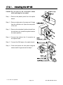
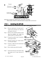
Installing OP-03 ...................................................................... 58
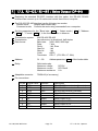
RS-422/ RS-485 / Relay output (OP-04) ..................................... 59
Installing OP-04 ...................................................................... 60
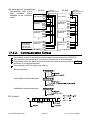
Communication Format........................................................... 61
Command List ......................................................................... 62
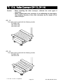
Roller Conveyor (OP-13, OP-14) ................................................ 64
18.
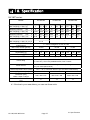
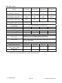
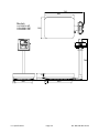
Specification..................................................................... 65
19.
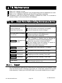
Maintenance..................................................................... 69
19.1.
Check Points Before Calling Maintenance Service ..................... 69
19.1.1.
Repair ..................................................................................... 69
Page 2
HV-WP/HW-WP Series
1. Compliance
1.1.1.
Compliance with FCC rules
Please note that this equipment generates, uses and can radiate radio frequency
energy. This equipment has been tested and has been found to comply with the limits
of a Class A computing device pursuant to Subpart J of Part 15 of FCC rules. These
rules are designed to provide reasonable protection against interference when this
equipment is operated in a commercial environment. If this unit is operated in a
residential area it may cause some interference and under these circumstances the
user would be required to take, at his own expense, whatever measures are
necessary to eliminate the interference.
(FCC = Federal Communications Commission in the U.S.A.)
1.1.2.
Classification of protection provided by enclosures
This equipment is designed to comply with the IP Code of IEC 529.
The "IP-65" code is explained as follows:
"IP"
International Protection.
"6"
Against ingress of solid foreign objects.
Dust-tight. No ingress of dust.
"5"
Against ingress of water with harmful effects.
Protected against water jets (no powerful jets). Water projected in jets
against the enclosure from any direction shall have no harmful effects.
Compliance with European Directive
This appliance features radio interference suppression and safety of electrical
equipment designed for certain voltage in compliance with valid EC Regulation
89/366/EEC and 73/23/EEC.
Note: The displayed value may be adversely affected under extreme electromagnetic
influences.
HV-WP/HW-WP Series
Page 3
2. Outline and Features
2. Outline and Features
These scales are designed to comply with IP-65 of IEC 529
The HV-WP series is a platform scale with 1/3000 resolution, and has a "triple
weighing range" function to select the weighing range.
The HW-WP series is a platform scale with 1/10000 resolution.
The scales have a fluorescent display so the weighing value can be read in dim light.
This type uses the AC power line as a power source.
Using the standard RS-232C serial interface, data can be output to a printer, and the
scale can be controlled or can be set by a command from a personal computer.
The counting mode function converts the total mass value (total weight) of articles to
be counted, to a count, when each of these articles assume the same mass value.
The scales can display the unit of percentage.
The accumulation function accumulates each weighing value and counts the number
of weighings using six figures.
The comparator function compares the display value with the upper limit value (HI),
lower limit value (LO) and displays the result. The result can be output by a buzzer if
option OP-03 is installed.
The simple batch function or full/dribble batch function can be used for filling up to a
target mass value. The status of a weighing value can be output if option OP-03 or
OP-04 is installed. The outputs are zero band, preliminary and final.
Using the optional RS-422/RS-485 serial interface and a computer, up to 16 scales
can be controled, if this option (OP-04) is installed in place of the RS-232C serial
interface.
The following parameters are stored in the product with no power supplied.
Unit mass of the counting mode
100% mass of the percentage mode
Total count and total mass of the accumulation function
Upper limit value and lower limit value of the upper / lower comparator function,
Final value, preliminary value and zero band of the full / dribble batch function or
Final value, preliminary value and zero band of the simple batch function
Calibration data
Parameters of the function table (f1 ~ f17)
2. Outline and Features
Page 4
HV-WP/HW-WP Series
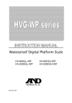
3. Unpacking
Models
HV-15KV-WP
HW-10KV-WP
Display Unit
Models
HV-60KV-WP
HW-60KV-WP
Pan
Base Unit
Display Unit
Pan
Main power cord
Models
HV-200KV-WP
HW-100KV-WP
HW-200KV-WP
Display Unit
Base Unit
Caution
Do not pull the load-cell cable.
Main power cord
Main power
Please confirm that the local
voltage and receptacle type
are correct for your scale.
Pan
All Accessories
Refer to the accessries list on the next
page. The combination of accessories is
according to the scale model.
Base Unit
3mm allen wrench
Caution
Do not pull the load-cell cable.
Main power cord
HV-WP/HW-WP Series
Page 5
Instruction manual
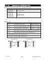
3. Unpacking
3.1.
Accessories and Options List
Accessories for the HV-WP series and HW-WP series
Models
HV-15KV-WP
HW-10KV-WP
HV-60KV-WP
HV-200KV-WP
HW-60KV-WP
HW-100KV-WP
HW-200KV-WP
Options List
A
A
Accessories
Instruction manual
A
A
A
A
3mm Allen wrench
Instruction manual
Cable or option name
Accessories
OP-02
5m extension loadcell cable
Tapping screw M4x10
OP-03
RS-232C interface/ Relay output/ Buzzer Connector JA:TCP0586
OP-04
RS-422/485 interface / Relay output
OP-13
Roller conveyor for HV-200KV-WP, HW-100KV-WP and HW-200KV-WP
OP-14
Roller conveyor for HV-60KV-WP and HW-60KV-WP
Connector
TM:BLA9
AX-KO577A-200 RS-232C cable, D-sub 25 pin, 2m
3. Unpacking
A
A
A
A
AX-KO1786-200
Page 6
A
A
AX-KO1786-200 RS-232C cable, D-sub 9 pin, 2m
AX-KO577A-200
A
A
HV-WP/HW-WP Series
4. Caution
4.1.
Precautions for Installing the Scale
Ground the scale, so that the user will not be subjected to an electric shock.
Do not handle the Main power cord with wet hands.
The AC plug is not water-resistant. Install it in an area where it does not get wet.
Do not install the scale where there is flammable or corrosive gas present.
Do not install the scale under water.
Do not pull, fold or arrange cables forcibly.
Consider the following conditions to get the most from your scale.
The best operation is where the temperature and relative humidity is stable, the place to
install the scale is a solid and level floor, there is no draft and the power source is stable.
Do not install the scale in direct sunlight.
Do not install the scale near heaters or air conditioners.
Do not install the scale near equipment which produces magnetic fields.
Do not install the scale in a place where it is apt to be charged with static electricity, or
where the relative humidity is lower than 45%RH. Plastic and isolators are apt to be
charged with static electricity.
Do not use an unstable power source.
4.2.
Precautions for Operating the Scale
Periodically ensure that the weighing value is correct.
Calibrate the scale before using and after moving it to another location.
Do not place anything on the weighing pan which is heavier than the weighing capacity
Do not drop anything upon the weighing pan.
Do not use a sharp instrument such as a pencil or ball-point pen to press the switches.
Press the switches gently using only your finger.
We recommend pressing the ZERO switch before each weighing to prevent possible error.
Close the calibration switch cover and the display rear cover to keep waterproof.
4.3.
Precautions for Storing the Scale
Do not disassemble the scale.
Do not use solvents to clean the scale.
For best cleaning of the display unit, wipe with a dry lint free cloth or a lint free cloth
which is moistened with warm water and a mild detergent.
Do not scratch the base unit with a brash.
Do not use a powerful water jet.
HV-WP/HW-WP Series
Page 7
4. Caution
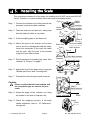
5. Installing the Scale
This procedure includes all of the steps for installing the HV-WP series and HW-WP
series. Therefore, on some models, there are some unnecessary steps.
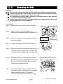
Step 1 Connect the indicator unit to the pole with the
accesory knobs and rubber washers.
Pole
Cable
Indicator
Knob
Rubber washer
Step 2 Take the base unit and pole out, taking care
that the load-cell cable is not pulled.
Step 3 Put the weighing pan on the base unit.
Step 4 Attach the pole to the bracket of the base
unit so as not to damage the load cell cable.
Insert the remainder of the load cell cable
into the pole. Affix the pole to the bracket
using two 3mm Allen screws.
Pan
Pole
Step 3
Step 2
Load-cell cable
Base unit
Pole
Allen wrench
Step 4
3mm allen screws
Bracket
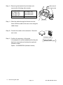
Step 5 Select the place for installing the scale. Also
consider "4. Caution" on page 7.
Step 6 Adjust the level of the base unit by using the
"Bubble spirit level" and "Leveling feet".
Step 7 Ground the scale using the earth terminal.
Bubble spirit level
Leveling feet
Step 6
OK
Power label
NG
Caution
Please confirm that the local voltage and
the receptacle type are correct for your
scale.
Step 8 Adjust the angle of the indicator unit using
the knobs on the side of indicator unit.
Step 9 Check the weighing accuracy. If the scale
needs calibration, refer to "14. Calibration".
on page 40.
5. Installing the Scale
Page 8
Earth
Step7
Earth terminal
Power terminals
Earth
Step8
Knob
HV-WP/HW-WP Series
5.1.
Removing the Pole
Caution
Remove the main power plug from the receptacle before removing the pole.
When removing the loadcell cable, do not pull the loadcell cable connector
forcibly and do not pull on the wires of the cable.
Do not bend the cable forcibly. Use care so that the load cell cable does not
touch the pan inside the base unit.
Avoid dust, static electricity and high humidity (or drops) because the inside
of the display unit is very sensitive.
Procedure
Step 1 Remove the power plug from the receptacle.
Connector
Screw and O ring
Step 2 Open the rear cover of the display unit.
Disconnect the loadcell cable connector gently.
Step 3 Remove the ferrite core and cable clamp from
the loadcell cable.
Step 4 Loosen the knobs to remove the display unit.
Ferrite core
Wind up 2 times
Loadcell cable
knob
Step 5 Remove four 3mm screws from the bottom cover
of the bracket for HV-60KV-WP, HV-200KV-WP,
HW-60KV-WP, HW-100KV-WP, HW-200KV-WP.
Step 6 Carefully remove the load cell cable from the
pole and the bracket. Especially, use care with
the HV-15KV-WP, HW-10KV-WP so that the
connector is not pulled forcibly.
Step 7 Arrange the cable so that it does not touch to
the weighing pan in the base unit. The untied
cable is at least 2m long. The optional
extension loadcell cable (OP-02) is 5m long.
HV-WP/HW-WP Series
Page 9
Cable clamp
Pole
Bracket (Middle and large size)
Pole
Bottom cover
3mm screws
5. 1. Removing the ploe
Allen wrench
Allen head screw
Step 8 Removing the bracket from the base unit,
requires the following allen wrench.
HV-15KV-WP,
HV-60KV-WP,
HW-10KV-WP,
HW-60KV-WP
5mm Allen wrench
HV-200KV-WP,
HW-100KV-WP,
HW-200KV-WP
6mm Allen wrench
Bracket
Step 9 Wind the cable through the ferrite core two
times. Affix the cable to the rear cover using the
cable clamp.
Step 10 Connect the cable to the connector. Close the
rear cover.
Step 11 Confirm the accuracy of the scale.
* An example of a scale installation after the pole
has been removed and includes the optional
Indicator holder
Option…AX:043005266 (Indicator holder)
5. 1. Removing the ploe
Page 10
Indicator holder
To be purchased
separately as an option.
HV-WP/HW-WP Series
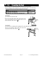
5.2.
Grounding the Scale
When using where there may be static electricity, ground the scale.
The grounding procedure depends on the scale model. Refer to the table below.
These procedures are only for grounding part of the scale.
Models
Refer to
Procedure
A
HV-15KV-WP, HW-10KV-WP
HV-60KV-WP, HV-200KV-WP
Procedure B
HW-60KV-WP, HW-100KV-WP, HW-200KV-WP
Procedure A
(HV-15KV-WP, HW-10KV-WP)
Secure the grounding cable using a M4 screw in the
screw hole between the two hexagon bolts on the
base unit bottom side. (Part of “ ”)
Base unit
bottom side
Levering feet
Procedure B
(HV-60KV-WP, HV-200KV-WP, HW-60KV-WP, HW-100KV-WP, HW-200KV-WP)
Secure the grounding cable using the screw that
secures the under cover. (Part of “ ”)
HV-WP/HW-WP Series
Page 11
Under cover
Base unit
bottom side
5. 2. Grounding the Balance
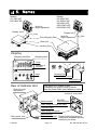
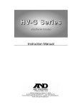
6. Names
Models
HV-15KV-WP
HW-10KV-WP
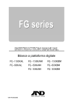
Models
HV-60KV-WP
HV-200KV-WP
HW-60KV-WP
HW-100KV-WP
HW-200KV-WP
Knob for
angle adjustment
Display Unit
Display Unit
Knob for
angle adjustment
Pole
Pan (Weighing Pan)
Pole
Base Unit
Leveling Foot
Display
Weighing condition
Weighing data
Units
STABLE
NET
ZERO
PT READY M+ 15kg
HI
CAP.
6kg
Indicator of
function
3kg
OK
NG
LO
OK
Max 3/6/15kg d=1/2/5g
Leveling Foot
Keys
Rear of Indicator Unit
Knob for angle
adjustment
Bubble Spirit Level
Leveling Foot
CAL switch is in a depth of 5cm.
Calibrating the scale to weigh correctly.
Use the proper OIML class calibration mass.
Inside of rear panel
Earth terminal
RS-232C
DIN connector
Cable clamp for load cell cable
Load cell cable
Cable clamp for option
Main power cord
6.Names
Earth terminal
Power line terminal Please Confirm that the local
voltage and receptacle type are
correct for your scale.
Page 12
HV-WP/HW-WP Series
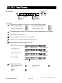
6.1.
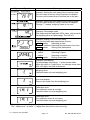
Display and Symbols
Display and Symbols
Meaning
Stability mark.
When the current weighing value is stable, this mark is
displayed, indicating a condition where the value is
readable.
Zero point mark.
With nothing on the weighing pan and pressing the
ZERO switch, this mark is displayed. The zero point is a
fundamental starting point to weigh anything.
A
A
A
A
A
A
A
A
A
A
A
A
Net mark.
Pressing the TARE switch, this mark is displayed with
net display.
Used to indicate that the mass of the container placed
on the pan has been subtracted from the gross value.
A
Preset tare mark.
Storing a tare with digital input, this mark blinks.
A
A
A
A
A
A
A
A
A
A
A
A
A
A
A
A
A
A
unit Example. Display of zero (zero point).
With nothing on the weighing pan and pressing A
the ZERO switch, this mark is displayed.
A
The zero point mark is displayed.
A
The stability mark is displayed.
A
A
Example. Display of the counting mode.
This mode uses the registered unit mass, and counts A
the amount of articles on the weighing pan. The unit is A
.
A
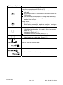
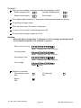
Accumulation mark.
Using the accumulation function, this mark is displayed.
Ready mark for the full/dribble batch function. The
meaning of the mark is as follows:
ON
The weighing value is within the zero-band.
OFF
The full/dribble batch process is above the
zero-band.
Blinking The start or end of the full/dribble batch
process in not within the zero-band.
The comparator indicator.
Using the comparator function and comparing a
weighing value with the upper and lower limits, the
result is indicated.
Using the full/dribble batch function, the full flow
gate indicator is OK, the dribble flow gate indicator
is HI and the zero band indicator is LO.
The weighing range indicator for the HV-WP series.
The current range is indicated.
Weighed mass value
STABLE
ZERO
HV-WP/HW-WP Series
Page 13
6.1. Display and Symbols
Display and Symbols
20 pieces Zero value
STABLE
PT
A
A
Example. Storing the unit mass of the counting mode.
A
The unit mass is stored, using 20 pieces of samples.
A
The zero value means that no articles are on the pan.
A
A
Example. Storing the unit mass of the counting mode.
A
The unit mass is stored, using 10 pieces of samples.
The sign "-" means "weighing value is not zero".
A
A
A
Example. Percentage mode.
A
This mode uses the registered 100% mass, and converts
A
the weighing value to a percentage. The unit is % .
A
A
Example. Display of the function table.
A
This function table sets parameters of items.
ENTER switch
Selecting an item.
A
∧ and < switches Selecting the parameter of an item. A
ENTER switch
Storing new parameters.
A
A
Example. Preset tare. Entering tare with digital input.
< switch
Selecting a figure.
A
∧ switch
Selecting a number.
A
ENTER switch
Storing a new tare.
A
A
Example. Hold display
A
The hold display is set using f12 of the function table.
When the value is "nearly-zero" or changes more than A
25% +30 digits, the hold is canceled.
A
Meaning
Weighing error.
Check the base unit and weighing pan.
Over load display.
Remove the mass from the weighing pan.
Calibration error.
The calibration mass is too light.
Check the base unit and weighing pan.
Calibration error.
The calibration mass is too heavy.
Check the base unit and weighing pan.
The "digit" is a unit of display, and is equivalent to the minimum measurable mass.
The " nearly-zero " is within ±5 digits from zero point in the unit of kg.
6.1. Display and Symbols
Page 14
HV-WP/HW-WP Series
A
A
A
A
A
A
A
A
A
A
A
A
Display and Symbols
Meaning
Does not display zero when the scale is turned on.
Remove anything that is on the weighing pan.
Perform zero point calibration.
Or
The weight value is unstable due to drift or vibration
when the scale is turned on.
A breeze or vibration may be affecting the
measurement.
Check around the weighing pan.
A
A
A
A
A
A
A
Total mass value of the accumulated data.
A
A
Comparator function, display is an upper limit.
Full/dribble batch function, the display is a final value.
A
Full/dribble batch function, the display is a preliminary A
value.
A
A
Comparator function, display is a lower limit.
Full/dribble batch function, the display is the zero band. A
Description of the weighing unit, weighing range and A
measurable minimum mass.
A
Accumulated data count.
CAP. MAX. 3/6/15kg d=1/2/5g
6.2.
Example: Displays the weight value by 5 g up to 15 kg.
Displays the weight value by 2 g up to 6 kg.
Displays the weight value by 1 g up to 3 kg.
Switches
Display and Symbols
HV-WP/HW-WP Series
A
A
Display ON/ OFF switch.
A
Note Standby status when power is connected.
A
A
ZERO switch.
When there is nothing on the weighing pan and the ZERO A
switch is pressed, the scale displays the mass value of zero A
and the zero point mark. Net is canceled, if it is displayed.
A
A
TARE switch.
Canceling the mass of a receptacle, case, bag, etc. which is A
put on the weighing pan, and does not weigh its mass.
A
A
RANGE switch, SAMPLE switch.
Changing weighing range for HV-WP series.(Refer to f2 ) A
Storing the unit mass, it is used to select a sample number.
A
In the function table, it is used to select a parameter.
A
Meaning
Page 15
6.2. Switches
Display and Symbols
Meaning
SET switch.
Turns the comparator on/off. (Refer to f6 )
Counting mode, it is used to enter the mode to store the
unit mass.
Percentage mode, it is used to enter the mode to store the
100% mass.
The full/dribble batch function, it is used as a start switch.
For the preset tare and selecting a calibration mass, it is
used to select a figure.
MODE switch.
Changing the current unit.
While setting modes, this switch is used for " storing a
parameter and proceeding to the next step".
F switch.
Full/dribble batch function, it is used to finish the process.
(Refer to f10 )
Hold switch. (Refer to f12 )
Comparator function, selects polarity (+,-).
A
A
A
A
A
A
A
A
A
A
A
A
A
A
A
A
A
A
PRINT switch.
Used to print or output data. (Refer to f5 )
Used to enter the function table.
Used to enter the mode to set a preset tare.
6.2. Switches
Page 16
HV-WP/HW-WP Series
A
A
A
A
A
A
A
A
A
A
A
7.
7.1.
Step
Step
Step
Step
Step
1
2
3
4
5
Step 6
Step 7
Step 8
Step 9
Step 10
Basic Operation
Turning the Scale on/off and Weighing
Ground the scale using the earth terminal.
Place nothing on the weighing pan.
Confirm that local voltage and receptacle type adapt to your scale.
The scale turns on/off using the ON/OFF switch alternately.
Check the accuracy of weighing. If you calibrate the scale, perform it after turning
the scale on for 30 minutes (warming up).
Press the ZERO switch to display zero. (with nothing on the weighing pan.)
Place an item on the weighing pan gently.
You can read the mass value after the stability mark is displayed.
Remove the item from the weighing pan.
Turn the scale using the ON/OFF switch off.
Memo
With the power cord connected, the scale consumes only the power for standby
status after turning off the scale. To shut down the power completely, disconnect the
power cord.
HV-WP/HW-WP Series
Page 17
7. Basic Operation
7.2.
Tare (And Net Display)
"Tare" is used to cancel the mass of a container, receptacle, case, bag, etc. which is
put on the weighing pan to contain the item to be weighed.
Caution
Using a tare value reduces the weighing range.
The current tare value is reset by pressing the ZERO switch or turning the
scale off. (Reset value is zero.)
The preset tare value must be within the minimum weighing range for the HV-WP series.
7.2.1.
The Way of Tare Input by Weighing
Step 1 Put the container item on the weighing pan.
Step 2 Wait for the stability mark to be displayed. Press the TARE switch. The display
becomes zero and the net mark is displayed.
Step 3 It is now possible to put something into the container. Wait for the stability mark to
be displayed and to read its net display.
Step 4 Remove all things on the weighing pan.
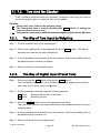
7.2.2.
The Way of Digital Input (Preset Tare)
Step 1 Press and hold the SET switch and press the TARE switch.
Then the blank or stored tare value is displayed. A blank display means that the
tare value is zero (reset value), and blinks.
Step 2 Set the preset tare value by using the following switches.
∧ switch
Selecting the number of the figure.
< switch
Selecting a figure.
Step 3 Press the ENTER switch to store the new preset tare value.
Then the scale displays a net value with the tare value subtracted from the gross
weighing value.
Step 4 It is then possible to put something into the container. Wait for the stability mark to
be displayed and to read its net.
Step 5 Remove all things from the weighing pan.
7. Basic Operation
Page 18
HV-WP/HW-WP Series
7.3.
7. Basic Operation
Weighing Range for the HV-WP Series
This is the function to select a weighing range for the HV-WP series.
The mass value is displayed within a selected range.
Select automatic range (f2 0) or manual range (f2 1) in the function table.
Operation and Performance
Function table
Meaning and purpose
f2 0
Automatic range
The weighing range changes automatically, if the weighing
value proceeds from narrow range to wide range when
placing articles on the weighing pan.
When there is nothing on the weighing pan and the zero point
mark is displayed, it changes to the minimum range
automatically.
Press the ZERO switch to change to the minimum range,
when there is nothing on the weighing pan and the zero point
mark is not displayed due to net display or zero error.
f2 1
Manual range
Press the RANGE switch to expand the range.
Press the RANGE switch to change to the minimum range,
when there is nothing on the weighing pan and the zero point
mark is displayed.
Press the ZERO switch and the RANGE switch to change to
the minimum range, when there is nothing on the weighing
pan and the zero point mark is not displayed due to net display
or zero error.
Weighing Range
Models
HV-15KV-WP
HV-60KV-WP
HV-200KV-WP
HV-WP/HW-WP Series
3kg,
15kg,
60kg,
Page 19
Weighing Range
6kg,
15kg
30kg,
60kg
150kg,
220kg
7. Basic Operation
A
A
A
A
A
A
A
A
A
A
A
A
A
A
A
A
A
A
A
A
A
A
A
7.4.
Mode Switch (Changing Unit and Mode)
Pressing the MODE switch, the display changes as follows. Refer to function table f3
for units. Usable units are according to the factory settings.
If the law in your area
premits, you may use all
of the units. Also, some
dealers may initially turn
off units which are not
regularly used.
Pound
Ounce
Pound-Ounce
Non metric units
Metric unit
Metric kg
Counting Mode
Percentage Mode
Inactive Comparator (f6)
and
Inactive Accumulation Function (f8 0)
Either function is active.
Comparator (f6 0 ~ f6 7)
Simple Batch Function (f6 8)
Full/Dribble Batch Function (f6 9)
Accumulation Function (f8 1)
Accumulation Count
M+
No Accumulation Data
Accumulation Value
M+
Active Simple Batch Function or
Active Full/Dribble Batch Function
(f6 8, f6 9)
Active Comparator (f6 0 ~ f6 7)
Final value
HI
Comparator
Upper limit
HI
Preliminary value OK
Comparator
Lower limit
LO
Zero band
7. Basic Operation
Page 20
LO
HV-WP/HW-WP Series
Explanation
The status of "Inactive comparator (f6)" is that comparator function (f6 0, f6 2, f6 4, f6 6)
is selected and the comparator is not used. The "active" or "Inactive" (ON/OFF) for the
comparator can be selected by pressing the SET switch alternately.
The following parameters are stored in the same memory. Therefore, the functions
can not be used at the same time. If you use each function, it will be necessary to
select the function from the function table, to set the parameters of HI,OK and LO, to
weigh it using the function.
Indicator and Output
HI
Upper/Lower Comparator Function (f6 0 ~ 7)
Upper limit
Simple Batch Function (f6 8)
Final value
Full/ Dribble Batch Function (f6 9)
Final value
HV-WP/HW-WP Series
Page 21
OK
LO
Lower limit
Preliminary
value
Preliminary
value
Zero band
Zero band
7. Basic Operation
8. Counting Mode
The counting mode is the function to convert the total mass value (total weight) of
articles to a count, when each of these articles assume the same mass value.
It is necessary to store a unit mass to count articles.
Even if the AC adapter or the batteries is removed, the unit mass is maintained in
non-volatile memory.
8.1.
Storing a Unit Mass
Step 1 Press the MODE switch to display the unit
.
Counting mode
Step 2 Press the SET switch to enter the mode to store a
unit mass.
Step 3 Press the ∧ switch to select the number of
STABLE
samples. The greater the quantity of samples, the
greater the accuracy of the count.
5 pieces, 10 pieces, 20 pieces, 50 pieces, 100 pieces
STABLE
Step 4 Put a container item on the weighing pan.
Press the TARE switch.
Step 5 Put in samples of number selected at step 3.
Press the ENTER switch to store it after the satbility
mark is displayed. Then the count is displayed.
Number of samples
A container(bowl)
Pan
STABLE
Caution
When the sample is too light and it is not possible Zeroing value
to calculate a unit mass, the scale displays lo ut
and returns to step 3. Increase the number of
samples. It is necessary to have more than 5 digits
in the unit of kg to weigh a sample.
When the unit mass is too light to store, the scale
STABLE
displays lo ut . . In this case, the unit mass will not be
stored even if the number of samples is increased.
Counts
Pressing the ENTER switch after lo ut . is
displayed, the next unit is displayed.
Step 6 Remove all things from the weighing pan.
8. Counting Mode
Page 22
Note
The pan shape depends
on the scale model.
HV-WP/HW-WP Series
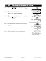
8.2.
Counting the Number of Articles
Step 1 Press the MODE switch to display the unit
.
Counting mode
Step 2 Store the articles unit mass.
Refer to "8.1 Storing a Unit Mass"
Storing a unit mass
A container(bowl)
Step 3 Place the container item only on the weighing pan.
Press the TARE switch.
Pan
STABLE
Zeroing value
Step 4 Put articles in the container item and read the
count.
STABLE
Step 5 Remove all things from the weighing pan.
Note
The pan shape depends
on the scale model.
HV-WP/HW-WP Series
Page 23
8. Counting Mode
9.
Percentage Mode
The percent mode is the function to display a mass value in the unit of "%".
Store a 100% mass value, in advance, to use this function.
The 100% mass value is stored in the scale even if the power is removed.
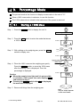
9.1.
Storing a 100% Mass
Step 1 Press the MODE switch to display the unit %.
Percentage mode
Step 2 Press the SET switch to enter the mode that stores
a 100% mass.
Step 3 With nothing on the weighing pan, press the ZERO
switch to display zero.
%
STABLE
Pan
STABLE
Zeroing value
100% mass
Step 4 Place the 100% mass on the weighing pan gently.
Press the ENTER switch, to store the 100% mass
after the stability mark is displayed. Then the
percentage is displayed.
Caution
When the sample is too light and it is not possible
to calculate a 100% mass, the scale displays lo .
and returns to step 3.
Pressing the ENTER switch after lo is displayed,
the next unit is displayed.
Step 5 Remove all things from the weighing pan.
9. Percentage Mode
Page 24
STABLE
Note
The pan shape depends
on the scale model.
HV-WP/HW-WP Series
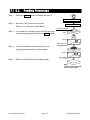
9.2.
Reading Percentage
Step 1 Press the MODE switch to display the unit %.
Percentage mode %
Step 2 Store the 100% mass of the article.
Refer to "9.1 Storing a 100% Mass "
Storing a 100% mass
A container(bowl)
Step 3 If a container is needed, place the tare item only
on the weighing pan and press the TARE switch.
Pan
STABLE
Zeroing value
Step 4 It is now possible to put something on the
weighing pan and read the percentage.
STABLE
Percentage
Step 5 Remove all things from the weighing pan.
Note
The pan shape depends
on the scale model.
HV-WP/HW-WP Series
Page 25
9. Percentage Mode
10. Accumulation Function
This function counts the number of weighed items, calculates the total mass value
and can display the number and accumulated mass value.
The accumulation function is displayed with up to 6 digits. The balance can not display 7 or
more digits, therefore the leading digits are not displayed.
Example: With 60K type, when importing the data of 17 accumulations of up to 60kg (60.000
X 17=1020.000), the balance displays this as “020.000”.
Set the parameters of the "accumulation function ( f8
advance, to use this function.
)" in the function table, in
The accumulation count and accumulated mass value are stored in the scale even if
the power is removed.
Operation and Switches
The display of the accumulation count has a blinking
without a unit.
The display of the accumulated mass value has a unit and a blinking
.
Pressing the MODE switch, the accumulation count and accumulated mass value are
displayed.
Pressing the ZERO switch in the accumulation function (
is blinking), the current
function resets. (The count and accumulated mass value become zero.)
Caution
The accumulation function can be used with the first weighing unit accumulated.
Parameter List and Word Definition
The "nearly-zero" is within ±5 digits from the zero point in the unit of kg.
The "digit", a unit of display, is equivalent to the minimum measurable mass.
The "zero point" is the fundamental starting point to weigh anything.
Function table
Meaning and purpose
Accumulation function not used.
f8 0
f8 1
f8 2
f8 3
The scale accumulates the data, if the F switch is pressed, when
the display is a positive stable value without nearly-zero. The next
accumulation can be performed after the display is nearly-zero or a
negative value.
The scale accumulates the data, if the F switch is pressed, when
the display is a stable value and without nearly-zero. The next
accumulation can be performed after the display is nearly-zero.
When the display is a positive stable value and without nearly-zero,
the scale accumulates the data automatically. The next
accumulation can be performed after the display is nearly-zero or a
negative value.
10. Accumulation Function
Page 26
HV-WP/HW-WP Series
A
A
A
A
A
A
A
A
A
A
A
A
Function table
Meaning and purpose
f8 4
When the display is a stable value and without nearly-zero, the
scale accumulates the data automatically. The next accumulation
can be performed after the display is nearly-zero.
Use
Recording the number and mass of articles removed from
the weighing pan. (Put the articles on the weighing pan.
Press the TARE switch at each removal.)
f8 5
At each finish of the full/dribble batch function, the scale accumulates
the data automatically.
Use
Packaging articles like a powder, it is used for recording the
bag number and total mass.
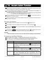
10.1. Preparation (Setting Parameters)
Step 1 Turn off the display.
Press the ON/OFF switch while the ZERO switch is
pressed and held. The function table is displayed.
Step 2 Press the ENTER switch to display an item of the
accumulation function ( f8 ).
Step 3 Select a parameter of the accumulation function
( f8 1 ~ f8 4 ) with the ∧ switch.
Step 4 Press the ENTER switch and the F switch to
display end . Press the ENTER switch to return
to the normal weighing mode.
HV-WP/HW-WP Series
Page 27
10. Accumulation Function
A
A
A
A
A
A
A
A
A
A
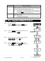
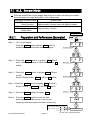
10.2. Operation and Performance (Examples)
Example 1
Weighing each article, the scale makes the accumulation according to f8 3 .
Step 1 Press the MODE switch to display
.
Step 2 Press the ZERO switch to reset the accumulation data.
Step 3 Return to the kg mode using the MODE switch.
Step 4 Put an article on the weighing pan. Wait for the stability mark to be displayed and
the value to be blinking. Remove the article and press the ZERO switch.
Step 5 Weigh additional articles using step 4.
Step 6 Press the MODE switch to display the number of articles and total mass with
.
Example 2
This example accumulates the articles that were removed from the weighing pan. The
function parameter is set to f8 4 .
Step 1 Enter into the kg mode using the MODE switch.
Put all articles on the weighing pan and press the TARE switch.
Step 2 Press the MODE switch to display
.
Step 3 Press the ZERO switch to reset the accumulation data.
Retun to kg mode with the MODE switch.
Step 4 Remove an article from the weighing pan. Wait for the stability mark to be
displayed and the value to be blinking. Press the TARE switch.
Step 5 Weigh additional articles using step 4.
Step 6 Press the MODE switch to display the number of articles and total mass with
10. Accumulation Function
Page 28
.
HV-WP/HW-WP Series
11. Upper/Lower Comparator Function
This function compares a display value with the upper limit (HI), the lower limit (LO)
and displays the result.
Set the "comparator function ( f6 0 ~ f6 7 )" parameters, upper limit value (HI) and
lower limit value (LO) in the function table, in advance, to use this function.
Install option OP-03 or OP-04, to use the relay output of the comparator.
Install option OP-03, to use the buzzer output of the comparator.
The settings are stored in the scale even if the power is removed. (Refer to Caution
on the next page.)
Comparator Indicators
Comparison results are displayed by indicators
.
Comparison Condition
Weighing value < lower limit value....................................LO is displayed and output.
Lower limit value ≦ weighing value ≦ upper limit value...OK is displayed and output.
Upper limit value< weighing value .....................................HI is displayed and output.
Parameter List and Word Definition
The decimal point is not displayed in the upper or lower limit value settings.
The " nearly-zero " is within ±5 digits from the zero point in the unit of kg.
The "digit", a unit of display, and is equivalent to the minimum measurable mass.
The "zero point" is the fundamental starting point to weigh anything.
Function table
f6 0
f6 1
f6 2
f6 3
Meaning and purpose
Pressing the SET switch, the scale always compares the current
display value. Press the SET switch again to stop the comparison.
The scale always compares the display value.
Pressing the SET switch, the scale always compares the display
value if not nearly-zero.
The scale always compares the display value if not nearly-zero.
f6 4
When the display value becomes stable after pressing the SET
switch, the scale compares the display value. It does not compare on
an unstable condition. If the SET switch is pressed again, the scale
stops the comparison.
f6 5
When the display value is stable, the scale compares the display
value. It does not compare on an unstable condition.
f6 6
When the display value becomes stable, while not nearly-zero,
after pressing the SET switch, the scale compares the display value. It
does not compare on an unstable condition. If the SET switch is
pressed again, the scale stops the comparison.
HV-WP/HW-WP Series
Page 29
11. Upper/Lower Comparator Function
A
A
A
A
A
A
A
A
A
A
A
A
A
A
A
A
A
Function table
f6 7
Meaning and purpose
A
When the display value becomes stable and not nearly-zero, the A
scale compares the value. It does not compare on an unstable A
condition.
Caution
The upper limit value (HI) must be greater than the lower limit value (LO).
The parameters of the upper limit value (HI) and the final value (HI) use the
same memory. The parameters of the lower limit value (LO) and the
preliminary value (OK) use the same memory.
The upper/lower comparator function, the simple batch function and the
full/dribble batch function can not be used at the same time because these
parameters use common memory.
11.1. Preparation (Setting Parameters)
Step 1 Turn off the display.
Press the ON/OFF switch while the ZERO switch is
pressed and held. The function table is displayed.
Step 2 Press the ENTER switch to display an item of the
comparator function ( f6 ).
Step 3 Select a parameter of the comparator function
( f6 0 ~ f6 7 ) with the ∧ switch.
Step 4 Press the ENTER switch and the F switch to display
end . Press the the ENTER switch to return to the
normal weighing mode.
11. Upper/Lower Comparator Function
Page 30
HV-WP/HW-WP Series
Last page
Step 5 If either of f6 0 , f6 2 , f6 4 , f6 6 has been
selected, press the SET switch to use the
comparator.
Either parameter is selected.
f6 0,
f6 4,
f6 2
f6 6
Step 6 Press the MODE switch to display the blinking HI.
Blinking HI
Step 7 Set the upper limit value by using the following
switches.
∧ switch
Selecting the number of a figure.
< switch
Selecting a figure.
F switch
,
Upper limit value
Selecting the polarity (+,-).
Step 8 Press the ENTER switch to store the new
parameter and display the blinking LO.
Step 9 Set the lower limit value by using the following
switches.
∧ switch
Selecting the number of a figure.
< switch
Selecting a figure.
F switch
Blinking LO
,
,
Lower limit value
Selecting the polarity (+,-).
Step 10 Press the ENTER switch to store the new
parameters and display the weighing mode.
If the lower limit value is greater than the upper
limit value, the scale returns to step 7.
HV-WP/HW-WP Series
,
Page 31
Weighing value and
comparison result
11. Upper/Lower Comparator Function
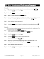
11.2. Operation and Performance (Examples)
Example 1
This example is set as follows:
Function table
f6 1
Upper limit value (HI)
Lower limit value (LO)
(The scale always compares the weight value
even when the value is nearly-zero.)
7.000kg
6.500kg
Case
The comparison starts at turning the scale on.
When the current value is less than 6.500kg, LO is displayed.
When the current value is 6.500kg to 7.000kg, OK is displayed.
When the current value is greater than 7.000kg, HI is displayed.
Example 2
This example is set as follows:
Function table
f6 4
Upper limit value (HI)
Lower limit value (LO)
(Pressing the SET switch, after the stability
mark is displayed, the scale compares the
current display value with the upper limit value
and the lower limit value immediately.)
2.000kg
-1.000kg
Case
Pressing the SET switch, the comparison is performed after displaying the stability
mark.
When the current value is less than -1.000kg, LO is displayed.
When the current value is -1.000kg to 2.000kg, OK is displayed.
When the current value is greater than 2.000kg, HI is displayed.
11. Upper/Lower Comparator Function
Page 32
HV-WP/HW-WP Series
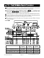
12. Full/Dribble Batch Function
This function changes the scale to a filling machine which subdivides a bulk product
( like grain) into loads of predetermined and virtually constant mass.
Set the parameters of the "comparator function ( f6 9 )", " full/dribble batch
sub-function ( f10 0 ~ f10 3 )" in the function table, final value (HI), preliminary value
(OK) and zero band (LO), in advance, to use this function.
Install option OP-03 or OP-04, to use the relay output of the full/dribble batch function.
In case of building up a filling machine with a scale and hopper, the performance and
processing product of the system are assumed to be as follows:
The settings are stored in the scale even if the power is removed. (Refer to Caution
on the next page.)
A
Zero band
Preliminary value
Final value
indicator/
indicator/
indicator/
A
LO relay output OK relay output HI relay output A
Gross < Zero band (Zero detection Level)
Net < Final - Preliminary
Final - Preliminary ≦ Net < Final
Final ≦ Net
HV-WP/HW-WP Series
ON / Make
OFF / Break
OFF / Break
OFF / Break
Page 33
OFF / Break
ON / Make
OFF / Break
OFF / Break
OFF / Break
ON / Make
ON / Make
OFF / Break
12. Full/Dribble Batch Function
A
A
A
A
Caution
The comparison of the full/dribble batch function is a one way sequence (not
reversible). If the display value becomes less than the final value after the
value reached a predetermined target value, neither HI nor LO is on.
The parameters of the upper limit value (HI) and the final value (HI) use the
same memory. The parameters of the lower limit value (LO) and the
preliminary value (OK) use the same memory.
The upper/lower comparator function, the simple batch function and the
full/dribble batch function can not be used at the same time because these
parameters use common memory.
Set the zero band greater than the tare value.
Operation
Pressing the SET switch, the scale starts the batch process.
Selecting a parameter from f10 0 or f10 2 of the full/dribble batch sub-function, the
cF switch works as the finish switch.
Parameter List and Word Definition
The "gross" is a total weighing value where the tare value is not subtracted.
The "net" is a measurement value with the tare value subtracted from the gross.
The "zero band" is the zero detection level.
The "zero point" is the fundamental starting point to weigh anything.
Comparator
Function table
Meaning and purpose
Full/dribble batch function.
f6 9
Full/dribble batch sub-function
Function table
Meaning and purpose
Reaching final value and pressing the F
f10 0
process is finished.
A
A
switch, the current
f10 1
Reaching final value and displaying the stability mark, the current
process is finished automatically.
f10 2
Pressing the SET switch, the scale automatically tares and starts
the full/dribble batch process. Reaching final value and pressing
the F switch, the current process is finished.
f10 3
Pressing the SET switch, the scale automatically tares and starts
the full/dribble batch process. Reaching final value and displaying
the stability mark, the current process is finished.
Hold
Function table
Meaning and purpose
The hold function is not used.
f12 0
12. Full/Dribble Batch Function
Page 34
A
A
A
A
A
A
A
A
A
A
A
A
A
HV-WP/HW-WP Series
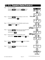
12.1. Preparation (Setting Parameters)
Step 1 Turn off the display.
Press the ON/OFF switch while the ZERO switch is
pressed and held. The function table is displayed.
Step 2 Press the ENTER switch to display an item of the
comparator function ( f6 ).
Step 3 Select a parameter of the full/dribble batch function
( f6 9 ) with the ∧ switch.
Step 4 Press the ENTER switch to store the new parameter
and display an item of the full/dribble batch
sub-function ( f10 ) .
Step 5 Select a parameter of the full/dribble batch
sub-function ( f10 0 ~ f10 3 ) with the ∧ switch.
Step 6 Press the ENTER switch and the F switch to display
end
.
Step 7 Press the ENTER switch to return to the normal
weighing mode.
HV-WP/HW-WP Series
Page 35
12. Full/Dribble Batch Function
Last page
Step 8 Press the MODE switch to display the blinking HI (of
the final value).
Step 9 Set the final value using the following switches.
∧ switch
Selecting the number of a figure.
< switch
Selecting a figure.
Blinking
HI
,
Final value
Step 10 Press the ENTER switch to store the new parameter
and display the blinking OK (of preliminary value).
Blinking
Step 11 Set the preliminary value using the following switches.
∧ switch
Selecting the number of a figure.
< switch
Selecting a figure.
Preliminary value
OK
,
Step 12 Press the ENTER switch to store the new parameter
and display the blinking LO (of zero band).
Blinking LO
Step 13 Set a zero band which is greater than the tare value,
using the following switches.
∧ switch
Selecting the number of a figure.
< switch
Selecting a figure.
Step 14 Press the ENTER switch to store the new parameter
and display the weighing mode.
12. Full/Dribble Batch Function
Page 36
,
Zero band
Weighing value and
comparison result
HV-WP/HW-WP Series
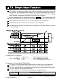
13. Simple Batch Function
This function compares a display value with the final value, preliminary value and
zero band for the full/dribble batch function. The result is indicated by zero band (LO
indicator), full flow (HI indicator) and dribble flow (OK indicator). Even if a weighing
value includes increase and decrease, this function can compare it.
Set the parameters of the "simple batch function ( f6 8 )", in the function table, final
value (HI), preliminary value (OK) and zero band (LO), in advance, to use this function.
Install option OP-03 or OP-04, to use the relay output of the comparison.
Install option OP-03, to use the buzzer output of the comparator.
The settings are stored in the scale even if the power is removed. (Refer to Caution
on the next page.)
Comparison Condition
Gross < Zero band ..............LO is displayed and output.
Final - Preliminary ≦ Net .........................OK is displayed and output.
Final ≦ Net .........................OK, HI are displayed and output.
Parameter List and Word Definition
The "gross" is a total measurement value where the tare value is not subtracted.
The "net" is a measurement value with a tare value subtracted from the gross.
The "tare" is an item put on the weighing pan and its mass is subtracted from the gross.
The "zero band" is the zero detection level.
The "zero point" is the fundamental starting point to weigh anything.
Function table
Meaning and purpose
f6 8
Simple batch function
HV-WP/HW-WP Series
Page 37
13. Simple Batch Function
A
A
Caution
The parameters of the upper limit value (HI) and a final value (HI) use the
same memory. The parameters of the lower limit value (LO) and the
preliminary value (OK) use the same memory.
The upper/lower comparator function, the simple batch function and the
full/dribble batch function can not be used at the same time because these
parameters use common memory.
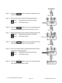
13.1. Preparation (Setting Parameters)
Step 1 Turn off the display.
Press the ON/OFF switch while the ZERO switch is
pressed and held. The function table is displayed.
Step 2 Press the ENTER switch to display an item of the
comparator function ( f6 ).
Step 3 Select a parameter of the simple batch function
( f6 8 ) with the ∧ switch.
Step 4 Press the ENTER switch and the F switch to display
end
.
Step 5 Press the ENTER switch to return to the normal
weighing mode.
13. Simple Batch Function
Page 38
HV-WP/HW-WP Series
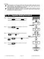
Last page
Step 6 Press the MODE switch to display the blinking HI (of
the final value).
Blinking
Step 7 Set the final value using the following switches.
∧ switch
Selecting the number of a figure.
< switch
Selecting a figure.
HI
,
Final value
Step 8 Press the ENTER switch to store the new parameter
and display the blinking OK (of preliminary value).
Blinking
Step 9 Set the preliminary value using the following switches.
∧ switch
Selecting the number of a figure.
< switch
Selecting a figure.
OK
,
Preliminary value
Step 10 Press the ENTER switch to store the new parameter
and display the blinking LO (of zero band).
Blinking LO
Step 11 Set the zero band using the following switches.
∧ switch
Selecting the number of a figure.
< switch
Selecting a figure.
,
Zero band
Step 12 Press the ENTER switch to store the new parameter
and display the weighing mode.
Weighing value and
comparison result
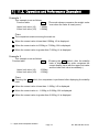
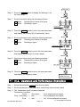
13.2. Operation and Performance (Examples)
Step 1 Select the parameter f6 8 of the function table.
Step 2 Set the parameters of the final value, preliminary value and zero band.
Step 3 The comparison result is always displayed.
Comparison Condition
Gross < Zero band ..........LO is displayed and output.
Final - Preliminary ≦ Net.....................OK is displayed and output.
Final
≦ Net ....................OK, HI are displayed and output.
HV-WP/HW-WP Series
Page 39
13. Simple Batch Function
14. Calibration (Adjusting the Scale)
The scale is an instrument which measures the "weight" and displays its "mass" value.
Calibration is the adjustment function so that the scale can weigh correctly.
There are three steps to calibration.
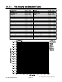
Gravity Acceleration Correction ... When a calibrated scale is moved to a distant
place, the scale can correctly weigh anything
by revising to a new local gravity acceleration.
Refer to the "Gravity Acceleration Table" on
the next page.
Calibration of the Zero Point ......... When there is nothing on the weighing pan, it is
the function that performs adjustment so as to
display the zero point mark .
Comment The zero point, is the fundamental starting point
to weigh anything, influences the performance
of scale.
Span Calibration.............................. The function that adjusts the span with a
calibrated mass so the scale can accurately
weigh anything within the weighing capacity.
Comment Span means the range of weighing capacity.
Use a calibration mass heavier than two thirds
of the weighing capacity.
Caution
Periodically check the accuracy of weighing. Calibrate the scale, if it is moved
to another location or the environment has changed.
It is not necessary to set the gravity acceleration correction, when calibrating
the scale with a calibration mass at the place where the scale is to be used.
14. Calibration (Adjusting Scale)
Page 40
HV-WP/HW-WP Series
14.1.1.
The Gravity Acceleration Table
Amsterdam
Athens
Auckland NZ
Bangkok
Birmingham
Brussels
Buenos Aires
Calcutta
Chicago
Copenhagen
Cyprus
Djakarta
Frankfurt
Glasgow
Havana
Helsinki
Kuwait
Lisbon
London (Greenwich)
Los Angeles
Madrid
HV-WP/HW-WP Series
9.813
9.800
9.799
9.783
9.813
9.811
9.797
9.788
9.803
9.815
9.797
9.781
9.810
9.816
9.788
9.819
9.793
9.801
9.812
9.796
9.800
m/s2
m/s2
m/s2
m/s2
m/s2
m/s2
m/s2
m/s2
m/s2
m/s2
m/s2
m/s2
m/s2
m/s2
m/s2
m/s2
m/s2
m/s2
m/s2
m/s2
m/s2
Page 41
Manila
Melbourne
Mexico City
Milan
New York
Oslo
Ottawa
Paris
Rio de Janeiro
Rome
San Francisco
Singapore
Stockholm
Sydney
Taiwan
Taipei
Tokyo
Vancouver, BC
Washington DC
Wellington NZ
Zurich
9.784
9.800
9.779
9.806
9.802
9.819
9.806
9.809
9.788
9.803
9.800
9.781
9.818
9.797
9.788
9.790
9.798
9.809
9.801
9.803
9.807
m/s2
m/s2
m/s2
m/s2
m/s2
m/s2
m/s2
m/s2
m/s2
m/s2
m/s2
m/s2
m/s2
m/s2
m/s2
m/s2
m/s2
m/s2
m/s2
m/s2
m/s2
14. Calibration (Adjusting Scale)
14.2. The Complete Calibration Procedure
14.2.1.
Gravity Acceleration Correction
Step 1 Turn on the display.
Open the rear cover of the display unit.
Press and hold the CAL switch, it is in the depth of
5cm, to enter the calibration mode.
Then Cal 0 is displayed.
Step 2 Press the ZERO switch to enter the gravity
acceleration correction mode.
Step 3 Set your local gravity acceleration using the following
switches.
∧ switch
Selecting the number of a figure.
< switch
Selecting a figure.
Step 4 Press the ENTER switch to store the new value.
Then Cal 0 is displayed.
Step 5 Press the CAL switch again. Then the scale returns to
the normal weighing mode.
14.2.2.
Preparation
Step 6 Confirm the environmental conditions as follows:
Maintain a constant temperature and stable power.
Install the scale on a solid floor where there is no draft, vibration, strong magetic
fields or direct sunlight.
Consider section "4. Caution".
Step 7 Display normal weighing for at least 30 minutes to warm up the scale.
14. Calibration (Adjusting Scale)
Page 42
HV-WP/HW-WP Series
14.2.3.
Calibration of the Zero Point
Step 8 Press and hold the CAL switch to enter
the calibration mode after displaying
normal weighing for 30 minutes.
Then Cal 0 is displayed.
Step 9 With nothing on the weighing pan, press
the ENTER switch while the stable mark is
displayed. The scale stores the current
condition as the zero point.
Weighing value
CAL switch
STABLE
STABLE
Stability mark
For several seconds
Step 10 The scale displays 5pn1 for several
seconds. Finishing the calibration mode
at this stage, proceed to step 14.
14.2.4.
Span Calibration
,
Step 11 Set the value of the calibration mass
using the following switches. (This initial
value is according to each model.)
∧ switch
Selecting the number of a
< switch
figure.
Selecting a figure.
Step 12 Place the mass on the weighing pan
which was set at step 11, press the
ENTER switch while the stable mark is
displayed. The scale then calculates the
span and stores it.
Mass value
15kg
STABLE
Stability mark
Step 13 The scale displays end at the finish.
Remove the mass from the weighing pan.
CAL switch
Step 14 Press the CAL switch to return to the normal
weighing mode.
HV-WP/HW-WP Series
Page 43
Weighing value
Note
The pan shape depends
on the scale model.
14. Calibration (Adjusting Scale)
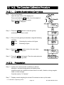
15. The Function Table
The function table is the function to store and refer items that determine the
performance of the scale. Each item has a parameter.
The parameters are maintained even without power applied.
15.1. The Procedure for Setting Parameters
Step 1 Turn off the display.
Press the ON/OFF switch while the ZERO switch is
pressed and held. The function table is displayed.
Step 2 Set parameters for each item using the following
switches.
∧ switch
Selecting the parameter of an item.
< switch
Selecting a figure.
F switch
Proceeding to Step 3 without storing the
parameter.
ENTER switch Storing a parameter for the current item
and proceeding to the next item.
Step 3 When the end of the table is reached,
displayed.
end is
Step 4 Press the ENTER switch to store the new parameters
and return to the normal weighing mode.
15. The Function Table
Page 44
HV-WP/HW-WP Series
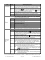
15.2. Parameter List
Item
Display
f1
Weighing
range
Unit
Baud rate
f2 0 #
f2 1
f3
f3
f3
f3
0 #
1
2
3
f4 0 #
f4 1
f4 2
f5 0 #
f5 1
f5 2
Output
mode
f5 3
f5 4
f5 5
f6 0 #
f6 1
Comparator f6 2
f6 3
f6 4
Meaning and purpose
Not used
Selects the way of changing weighing range for HV-WP series.
Automatic range
Manual range using the RANGE switch.
Selection of the first unit at the time when the scale turns on.
Kg
Lb
Oz
lb-oz
Selects the transmission rate of the serial interface (RS-232C/ 422/485).
2400bps
4800bps
9600bps
Mode selection for the serial interface (RS-232C/ 422/485).
Stream mode. (Refer to "16.2 Stream Mode")
Command mode. (Refer to "16.3 Command Mode")
Data is output, when the PRINT switch is pressed.
Auto-print +
When the display becomes a positive stable value without
nearly-zero, the scale outputs the data automatically. Next output can
be performed after the display becomes nearly-zero or a negative
value.
Auto-print +/When the display becomes a stable value without nearly-zero,
the scale outputs the data automatically. Next output can be
performed after the display becomes nearly-zero.
At each finish of full/dribble batch function, the data is output.
Selects the comparator mode.
Pressing the SET switch, the scale always compares the current
display value. Press the SET switch again to stop the comparison.
The scale always compares the display value.
Pressing the SET switch, the scale always compares the display
value when not nearly-zero. Press the SET switch again to stop the
comparison.
The scale always compares the display value when not
nearly-zero.
When the display value becomes stable after pressing the SET switch, the
scale compares the display value. It does not compare on an unstable
condition. If the SET switch is pressed again, the scale stops the comparison.
The "#" is factory settings. The "nearly-zero" is within ±5 digits from zero point in the unit of kg.
HV-WP/HW-WP Series
Page 45
15. The Function Table
A
A
A
A
A
A
A
A
A
A
A
A
A
A
A
A
A
A
A
A
A
A
A
A
A
A
A
A
A
A
A
A
A
Item
Display
Comparator f6 5
f6 6
f6 7
f6 8
f6 9
Buzzer
f7
f7
f7
f7
f7
f7
f7
f7
f7
0 #
1
2
3
4
5
6
7
8
f8 0 #
f8 1
f8 2
Accumulation function
f8 3
f8 4
f8 5
Meaning and purpose
A
When the display value becomes stable, the scale compares the
display value. It does not compare on an unstable condition.
When the display value becomes stable when not nearly-zero
after pressing the SET switch, the scale compares the display value.
It does not compare on an unstable condition. If the SET switch is
pressed again, the scale stops the comparison.
When the display value becomes stable when not nearly-zero, the scale
compares the value. It does not compare on an unstable condition.
Simple batch function. (Refer to section 13.)
Full/dribble batch function. (Refer to section 12.)
The condition of the buzzer on option OP-03 by comparator
function or full/dribble batch function.
No buzzer.
The buzzer sounds at LO.
The buzzer sounds at OK.
The buzzer sounds at LO and OK.
The buzzer sounds at HI.
The buzzer sounds at LO and HI.
The buzzer sounds at OK and HI.
The buzzer sounds at LO, OK and HI.
The buzzer sounds at finishing the full/dribble batch process.
The condition of the accumulation function
Accumulation function not used.
The scale accumulates the data, if the F switch is pressed, when
the display becomes a positive stable value without nearly-zero.
Next accumulation can be performed after the display becomes
nearly-zero or a negative value.
The scale accumulates the data, if the F switch is pressed, when the
display becomes a stable value without nearly-zero. Next accumulation
can be performed after the display becomes nearly-zero.
When the display becomes a positive stable value without nearly-zero,
the scale accumulates the data automatically. Next accumulation can be
performed after the display becomes nearly-zero or a negative value.
Use After weighing the first unit sample, one after another, it
records the total count and total weight value.
When the display becomes a stable value without nearly-zero, the
scale accumulates the data automatically. Next accumulation can
be preformed after the display becomes nearly-zero.
Use
Recording number and mass of articles removed from the
weighing pan. (Put articles on the weighing pan. Press
TARE switch at each removal.)
At each finish of the full/dribble batch function, the scale
accumulates the data automatically.
Use
Packing articles like a powder. used for recording the bag
number and total mass.
A
A
A
A
A
The "#" is factory settings. The "nearly-zero" is within ±5 digits from zero point in the unit of kg.
15. The Function Table
Page 46
HV-WP/HW-WP Series
A
A
A
A
A
A
A
A
A
A
A
A
A
A
A
A
A
A
A
A
A
A
A
A
A
A
A
A
A
A
A
A
Item
Display
Meaning and purpose
A
f9
Not used
The details of the full/dribble batch function (f6 9)
A
Reaching final value and pressing the F switch, the current A
f10 0 #
process is finished.
A
Reaching final value and displaying the stability mark, the current A
Full/Dribble f10 1
process is finished automatically.
A
batch
Pressing the SET switch, the scale automatically tares and starts A
sub-func-ti
the
full/dribble batch process. Reaching final value and pressing A
f10
2
on
the F switch, the current process is finished.
A
f10 3
Pressing the SET switch, the scale automatically tares and starts A
the full/dribble batch process. Reaching final value and A
displaying the stability mark, the current process is finished.
A
Address for RS-422 / RS-485 for option OP-04
Address
Hold
Averaging
Precision
of unit
mass
Format
A
A
This address can be set from 01 to 99. It is possible for a
A
computer to control the scale assigned an address.
A
(RS-232C should be set to "00".)
f11 00#
Use
f11 01
~
f11 99
The function to hold the current display value. When the value
becomes nearly-zero or the weighing value changes more than
25% +30 digits, hold display is canceled.
f12 0 # Not used
The hold function is ON or OFF alternately by the F switch.
f12 1
Displaying the stability mark, the display is held.
f12 2
Selects readability and response.
f13 0 # Fast response, sensitive value
Ú
f13 1
Slow response, stable value
f13 2
Selects a storable minimum unit mass in the counting mode.
f14 0 # Stores a unit mass in the unit of a digit.
Stores a unit mass in the unit of one eighth digit.
f14 1
Stores a unit mass, if the total of the sample mass is greater than
f14 2
5 digits.
Refer to "16.1. Data Format".
f15 0 # Format 1. (A&D general format for scales, balances)
Format 2. (Older HV-A/ HW-A format)
f15 1
Not used
f15 2
Format 1 (Return command is available for all commands.)
f15 3
Not used.
f16
The function number “f17” is not displayed.
f17
When displaying 000000, press the ENTER switch to cancel.
The "#" is factory settings
The "nearly-zero" is within ±5 digits from zero point in the unit of kg.
The "digit", a unit of display, is equivalent to the minimum measurable mass.
HV-WP/HW-WP Series
Page 47
15. The Function Table
A
A
A
A
A
A
A
A
A
A
A
A
A
A
A
A
A
A
A
16. RS-232C Serial Interface
Note When the RS-232C serial interface is used, be sure to set the "Address ( f11 ) " to "( 00 )".
The RS-232C interface has the following two modes.
Stream mode
Outputs data continuously and can be used for printing data.
Command mode Controls the scale using commands from a computer.
Set the parameters for the "Baud rate ( f4 )", " Output mode ( f5 )" and " Format
( f15 )", in the function table, in advance.
There are option cables as follows:
AX-KO577A-200 RS-232C cable, D-sub 25 pin, 2m
AX-KO1786-200 RS-232C cable, D-sub 9 pin, 2m
Transmission system
Transmission
Data format
EIA RS-232C
Asynchronous, bi-directional, half-duplex
Baud rate:
2400, 4800, 9600 bps
Data:
7 bits
Parity:
1 bit, Even
Start bit
1 bit
Stop bit
1 bit
Code
ASCII
Terminator CR LF (CR: 0Dh, LF: 0Ah)
Pin connections
Pin No.
1
2
3
4
5
6
7
8
Circuits
DSR
Din connector
(socket)
3
SG
5
Direction
Description
Input
Output
Receive data
Transmit data
-
Signal ground
Output
-
Data set ready
Inside of Rear panel
6
7
TXD
RXD
Signal name
RXD
TXD
SG
DSR
-
8
1
4
RS-232C interface board
2
DIN connector (socket)
DIN plug
Adaptable connector
16. RS-232C Serial Interface
DIN 8pin, (TCP0586)
Page 48
Cable clamp
HV-WP/HW-WP Series
A
A
A
A
A
A
A
A
16.1. Data Format
16. RS-232C Serial Interface
Bit Format
Format 1
There are four headers for the type of data and weighing condition.
Stable weighing data
Unstable weighing data
Stable counting data
Out of range ( Over)
The weighing data consists of 9 characters including decimal point and polarity.
The polarity is always output.
There are three units. The unit is 3 characters.
In case of "out of range", numbers become all 9’s.
The terminator is always output as CR LF.
Data in the unit of kg
S T , + 0 0 0 1 2 . 4 0 c k g
Header
Counting mode
Unit Terminator
Weighing value
Unit Terminator
O L , + 9 9 9 9 9 . 9 9 c k g
Header
Definition of symbols
CR (carriage return)
0Dh
Weighing value
S T , + 0 0 0 3 0 0 . 0 c c %
Header
Out of range
Unit Terminator
Q T , + 0 0 0 0 3 0 0 0 c P C
Header
Percentage mode
Weighing value
Polarity
LF (line feed)
0Ah
Space
20h
HV-WP/HW-WP Series
Page 49
16. RS-232C Serial Interface
Format 2
There are four headers for the type of data and weighing condition.
Stable weighing data
Unstable weighing data
Stable counting data
Out of range
The weighing data consists of 7 characters including decimal point and polarity.
The polarity is always output.
There are three units. The unit is 2 characters.
In case of "out of range", numbers become all 9’s.
The terminator is always output as CR LF.
Caution
When the data is longer than 7 characters in the counting, precentage mode
or accumulation function, the overflow is ignored.
Data in the unit of kg
S T , + 0 0 2 . 4 0 k g
Header Weighing value Unit Terminator
Counting mode
Q T , + 0 0 3 0 0 0 P C
Header Weighing value Unit Terminator
Percentage mode
S T , + 0 3 0 0 . 0 c %
Header Weighing value Unit Terminator
Out of range
O L , + 9 9 9 . 9 9 k g
Header
Definition of symbols
CR (carriage return)
0Dh
Polarity
LF (line feed)
0Ah
Space
20h
16. RS-232C Serial Interface
Page 50
HV-WP/HW-WP Series
16.2. Stream Mode
The scale outputs the current display data at the time when refreshing the display.
The scale does not output data while in the setting mode.
Averaging of function table
Refresh rate
Approximately 7 times/s while the display is unstable,
f13 0 Fast response
Sensitive value
Approximately 4 times/s when the display is stable
f13 1
Ú
Approximately 4 times/s
f13 2 Slow response
Stable value
A
A
A
A
Display off
16.2.1.
Preparation and Performance (Examples)
Step 1 Turn off the display.
Press the ON/OFF switch while the ZERO switch is
pressed and held. The function table is displayed.
Press and hold
Press
F u n c t i o n ta b l e
Step 2 Press the ENTER switch to display f4 ("Baud
rate"). Select a parameter of "Baud rate" with the ∧
B au d r a t e
switch.
Step 3 Press the ENTER switch to display f5 ("Output
mode").
Select "Stream mode ( f5 0 )" with the ∧ switch.
Stre am m ode
Step 4 Press the ENTER switch to display f15 ("Format").
Select "Format 1 ( f15 0 )" with the ∧ switch.
F or ma t 1
Step 5 Press the ENTER switch to display end .
Step 6 Press the ENTER switch to store the new
parameters. The scale returns to the normal
weighing mode and outputs the data continuously.
ST,0000.000 kg
US,0010.645 kg
Weighing value
ST,0010.644 kg
HV-WP/HW-WP Series
Page 51
16. RS-232C Serial Interface
16.3. Command Mode
The command mode is the function which can perform "output data", "controlling the
scale" and "setting parameters" by a command transmitted from a computer
Caution
16.3.1.
Allow at least 500 milliseconds between commands.
Command List
The following explanation uses "Format 1 ( f15 0 )"
Data output
The current weighing data is output.
Template
Q
Command
Reply
Selection of mode and unit
Selects the mode and unit. This is the same as the
Template
U
Command
Reply
The scale changes mode and unit.
Zero
Tare
MODE
switch.
The current mass value is set to the zero point.
This is the same as the ZERO switch.
Template
Z
Command
Reply
The mass value becomes zero and the zero point mark is displayed.
The current mass value is set to zero after placing a tare (container, receptacle, case,
etc) and the net value is displayed. This is the same as the TARE switch.
Template
T
Command
Reply
The current mass value becomes zero and the net mark is displayed.
Cancel of tare
The display value becomes the gross and the net mark is turned off. (The tare value
becomes zero.)
Template
CT
Command
Reply
Gross is displayed and the net mark is turned off.
16. RS-232C Serial Interface
Page 52
HV-WP/HW-WP Series
Preset tare
The tare value is set and the net value is displayed. The set value is a 5 digit
numerical value with a polarity sign and does not contain a decimal point.
Template
PT, [parameter]
Command
Reply
Net is displayed and the net mark is displayed.
Upper limit value
An upper limit value is stored. The set value is a 5 digit numerical value with a polarity
sign and does not contain a decimal point.
Template
HI, [parameter]
Command
Reply
The upper limit value is stored.
Caution
The upper limit value must be greater than the lower limit value.
Lower limit value
A lower limit value is stored. The set value is a 5 digit numerical value with a polarity
sign and does not contain a decimal point.
Template
LO, [parameter]
Command
Reply
The lower limit value is stored.
Caution
The lower limit value must be less than the upper limit value.
Accumulation data output
The accumulated data is output.
Template
A
Command
Reply
Accumulation count output
The number of accumulated data is output.
Template
N
Command
Reply
Reset of Accumulation data and Accumulation count
The data and number of accumulations become zero.
Template
CA
Command
Reply
The data and number of accumulations become zero.
HV-WP/HW-WP Series
Page 53
16. RS-232C Serial Interface
Final value
The final value is stored. The set value is a 5 digit numerical value with a polarity sign
and does not contain a decimal point.
Template
S0, [parameter]
Command
Reply
The value is stored.
Preliminary value
The preliminary value is stored. The set value is a 5 digit numerical value with a
polarity sign and does not contain a decimal point.
Template
S1, [parameter]
Command
Reply
The value is stored.
Zero band
The zero band is stored. The set value is a 5 digit numerical value with a polarity sign
and does not contain a decimal point.
Template
S2, [parameter]
Command
Reply
The value is stored.
16. RS-232C Serial Interface
Page 54
HV-WP/HW-WP Series
16.3.2.
Example of Setting Parameters
Step 1 Turn off the display.
Press the ON/OFF switch while the ZERO switch is
pressed and held. The function table is displayed.
Display off
Press and hold
Press
Step 2 Press the ENTER switch to display f4 ("Baud rate").
Select a parameter of "Baud rate" with the ∧ switch.
Step 3 Press the ENTER switch to display f5 ("Output
mode").
Select "Command mode ( f5 1 )" with the ∧ switch.
Function table
Baud rate
Step 4 Press the ENTER switch to display f15 ("Format").
Command mode
Select "Format 1 ( f15 0 )" with the ∧ switch.
Step 5 Press the ENTER switch to display end .
Step 6 Press the ENTER switch to store the new parameters.
The scale returns to the normal weighing mode.
Format 1
Step 7 When the computer transmits a command, the scale
replies.
Weighing value
HV-WP/HW-WP Series
Page 55
16. RS-232C Serial Interface
17. Options
17.1. Extension Cable (OP-02)
This cable is used for installing the indicator away from the base unit.
This loadcell cable is 5m long.
Refer tos " 5.1. Removing the Pole" for the way to remove the pole.
Caution
Calibrate the scale after connecting this cable.
Do not connect more than two extension cables.
Connector case
Extension cable
Connect to the indicator.
Connect to the front connector
on the connector board.
Packing C
Cap
Tapping screw
Connector board M4x10 of accessory
Attachment
The loadcell cable from the base unit.
Connect to the rear connector on the
connector board.
2m loadcell cable (at least).
5m extension cable
Base unit
Indicator
Indicator holder
To be purchased separately as an option.
AX:043005266
17.1. Extension cable (OP-02)
Page 56
Note
The pan shape depends
on the scale model.
HV-WP/HW-WP Series
17.2. RS-232C/ Relay Output/ Buzzer (OP-03)
Note When the OP-03 is used, be sure to set the "Address ( f11
) " to "( 00 )".
This option replaces the standard RS-232C interface, refer to "16. RS-232C Serial
Interface" for specification of RS-232C.
The following option cables can be used, when you do not use the relay output.
AX-KO577A-200 RS-232C cable, D-sub 25 pin, 2 m
AX-KO1786-200 RS-232C cable, D-sub 9 pin, 2 m
Pin connections
Adaptable connector
Circuits
Pin No.
1
2
3
4
5
6
7
8
Signal name
HI
RXD
TXD
LO
SG
OK
DSR
COM
Direction
Output
Input
Output
Output
Output
Output
-
Description
Relay output of HI
Receive data
Transmit data
Relay output of LO
Signal ground (RS-232C)
Relay output of OK
Data set ready
Relay common terminal
DIN 8pin, JA:TCP0586 (of accessory)
Din connector on (socket)
OK
Relay
DSR
3
SG
5
RXD
Relay
Solid-state-relay
HV-WP/HW-WP Series
6
7
TXD
8
1
4
2
HI
LO
COM
Maximum voltage
Maximum current
Maximum resistance
Page 57
DC50V
DC100mA
8Ω
17.2. OP-03, Options
A
A
A
A
A
A
A
A
A
17.2.1.
Installing the OP-03
Caution Do not pull on the connected cables
while opening the rear panel.
Step 1 Remove the plastic panel from the option
board.
Step 2 Remove eight pairs of screws and O rings
from the indicator unit. Open the rear panel
of the unit.
Step 3 Remove the standard interface board from
the indicator unit. Install the option board at
the same position.
Step 4 Connect the cable to the J1 connector on
the option board.
Step 5 Connect the DIN plug to the option board.
Step 6 Close and secure the rear panel using the
screws and O rings removed at step 2.
17.2. OP-03, Options
Page 58
HV-WP/HW-WP Series
17.3. RS-422/ RS-485 / Relay Output (OP-04)
Replacing the standard RS-232C interface with this option, the RS-422/ RS-485
interface can connect up to 16 scales and control them from a computer.
The RS-422/ RS-485 interface has the following two modes.
Stream mode
Outputs data continuosly.
Command mode Controls the scale using commands from a computer.
Set the parameters for the "Baud rate ( f4 )", " Output mode ( f5 )", "Address
( f11 )", " Format ( f15 )", in the function table, in advance.
Transmission system
Transmission
Data format
EIA RS-422/ RS-485
Asynchronous, bi-directional, half-duplex
Baud rate:
2400, 4800, 9600 bps
Data:
7 bits
Parity:
1 bit, Even
Start bit
1 bit
Stop bit
1 bit
Code
ASCII
Terminator CR LF (CR: 0Dh, LF: 0Ah)
Address
01 ~ 99
Relay
Solid-state-relay
Maximum voltage
Maximum current
Maximum resistance
Adaptable connector
Address parameter ( f11 ) of the function table.
DC50V
DC100mA
8Ω
TM:BLA9 (of accessory)
Pin connections
Pin No.
1
2
3
4
5
6
7
8
9
HV-WP/HW-WP Series
Signal name
SDA
SDB
RDA
RDB
TRM
HI
OK
LO
COM
Direction
Output
Output
Input
Input
Output
Output
Output
-
Page 59
Description
RS-422/485 transmission A terminal
RS-422/485 transmission B terminal
RS-422/485 receive A terminal
RS-422/485 receive B terminal
120Ω terminator
Relay output of HI
Relay output of OK
Relay output of LO
Relay common terminal
17.3. OP-04, Options
A
A
A
A
A
A
A
A
A
A
Relay
Circuits
RS-422 input
RS-485 input
RS-485 output
RS-422 output
RS-422/485 terminal
Relay output
Selection switch for the RS-422/ RS-485 interface
Selects either of RS-422 or RS-485 interface using a switch on the board.
17.3.1.
Installing the OP-04
Caution Do not pull on the connected cables while opening the rear panel.
Step 1 Remove eight pairs of screws and O
rings from the indicator unit. Open the
rear panel of the unit.
Step 2 Remove the standard interface board
from the indicator unit. Install the
option board at the same position.
Step 3 Connect the cable to the J3 connector
on the option board.
Step 4 Wire the connector for J1 and connect
it to the option board.
Step 5 Connect a cable from the transformer
to the J2 connector.
Step 6 Set a interface type with the switch.
Step 7 Close and secure the rear panel using
the screws and O rings removed at
step 1.
17.3. OP-04, Options
Page 60
HV-WP/HW-WP Series
An example of connection
RS-422
The polarities (A,B) of the
host
computer
signal
SDA
depends on the computer Host computer SDB
RDA
model.
RDB
Connect the
terminator to
the ones farthest from the
host computer.
17.3.2.
Terminator
(May be built in the
host computer)
RS-485
A
Host computer
Terminator
(May be built in the
host computer)
B
SDA
HV-WP/HW-WP SDB
Address=01
RDA
RDB
TRM
HV-WP/HW-WP SDA
SDB
Address=01
RDA
RDB
TRM
HV-WP/HW-WP SDA
Address=02 SDB
RDA
RDB
TRM
SDA
HV-WP/HW-WP SDB
Address=02
RDA
RDB
TRM
SDA
HV-WP/HW-WP SDB
Address=10
RDA
RDB
TRM
SDA
HV-WP/HW-WP SDB
Address=10
RDA
RDB
TRM
Communication Format
Commands consist of an address and the same command as for the RS-232C.
The address of the equipment is inserted in the first part of the command.
Commands return the same command when the communication format is f15 31
and there is no data transmitted.
If the address is 23, the reply is as follows:
Normal response
Impossible command response
Undefined command response
Bit format
HV-WP/HW-WP Series
Page 61
17.3. OP-04, Options
17.3.3.
Command List
The following explanation uses "Format 1 ( f15 3 )" assuming 23 as the address.
Data output
The current weighing data is output.
Template
Q
Command
Reply
Selection of mode and unit
Zero
Tare
Selects the mode and unit. This is the same as the
Template
U
Command
Reply
The scale changes mode and unit.
MODE
switch.
The current mass value is set to the zero point.
This is the same as the ZERO switch.
Template
Z
Command
Reply
The mass value becomes zero and the zero point mark is displayed.
The current mass value becomes zero after placing a tare (receptacle, case, etc) and
the net is displayed. This is the same as the TARE switch.
Template
T
Command
Reply
The current mass value becomes zero and the net mark is displayed.
Cancel of tare
The display value becomes the gross and the net mark is turned off. (The tare value
becomes zero.)
Template
CT
Command
Reply
Gross is displayed and the net mark is turned off.
Preset tare
The tare value is set and the net value is displayed. The set value is a 5 digit
numerical value with a polarity sign and does not contain a decimal point.
Template
PT, [parameter]
Command
Reply
Net is displayed and the net mark is displayed.
Upper limit value
An upper limit value is stored. The set value is a 5 digit numerical value with a polarity
sign and does not contain a decimal point.
Template
HI, [parameter]
Command
Reply
The upper limit value is stored.
Caution
The upper limit value must be greater than the lower limit value.
17.3. OP-04, Options
Page 62
HV-WP/HW-WP Series
Lower limit value
A lower limit value is stored. The set value is a 5 digit numerical value with a polarity
sign and does not contain a decimal point.
Template
LO, [parameter]
Command
Reply
The lower limit value is stored.
Caution
The lower limit value must be less than the upper limit value.
Accumulation data output
The accumulated data is output.
Template
A
Command
Reply
Accumulation count output
The number of accumulated data is output.
Template
N
Command
Reply
Reset of Accumulation data and number
The data and number of accumulations become zero.
Template
CA
Command
Reply
The data and number of accumulations become zero.
Final value
The final value is stored. The set value is a 5 digit numerical value with a polarity sign
and does not contain a decimal point.
Template
S0, [parameter]
Command
Reply
The value is stored.
Preliminary value
The preliminary value is stored. The set value is a 5 digit numerical value with a
polarity sign and does not contain a decimal point.
Template
S1, [parameter]
Command
Reply
The value is stored.
Zero band
The zero band is stored. The set value is a 5 digit numerical value with a polarity sign
and does not contain a decimal point.
Template
S2, [parameter]
Command
Reply
The value is stored.
HV-WP/HW-WP Series
Page 63
17.3. OP-04, Options
17.4. Roller Conveyor (OP-13, OP-14)17.3. OP-04, Options
Caution
- When installing the roller conveyor, calibrate the scale again if
necessary.
- When installing the roller conveyor, if not calibrating the scale again,
the weighing capacity of the scale decreases by the weight of the
roller conveyor
OP-13
This option can be used with the following models.
HV-200KV-WP,
HW-100KV-WP,
HW-200KV-WP
OP-14
This option can be used with the following models.
HV-60KV-WP,
HW-60KV-WP
17.4. OP-13, OP-14, Options
Page 64
HV-WP/HW-WP Series
18. Specification
HV-WP series
Models
Weighing Capacity
HV-15KV-WP
[kg]
Min. weighing (1 digit) [g]
Weighing Capacity
HV-60KV-WP
HV-200KV-WP
3
6
15
15
30
60
60
150
220
1
2
5
5
10
20
20
50
100
6
15
30
30
60
150
150
300
500
0.01
0.01
0.02
0.05
0.05
0.1
0.2
[lb]
#
Min. weighing (1 digit) [lb]
#
Weighing Capacity
[oz]
#
96
240
480
480
960
2400
2400
4800
8000
Min. weighing (1 digit) [oz]
#
0.05
0.1
0.2
0.2
0.5
1
1
2
5
Weighing Capacity
0.002 0.005
[lb_oz] #
30 lb
Min. weighing (1 digit) [lb_oz] #
Number of samples in counting
mode [pieces]
Max. count number [pieces]
0.1 oz
Display
Repeatability [g]
Linearity [g]
Span drift
---
A
5(can be changed to 10、20、50、100)
15,000
12,000
A
A
A
A
A
A
A
A
A
A
11,000
A
7 segment fluorescent display, Character height 20mm
A
±1
±2
±5
±5
±10 ±20 ±20 ±50 ±100 A
±1
±2
±5
±5
±10 ±20 ±20 ±50 ±100 A
20ppm/°
C typ. (5°
C ~ 35°
C)
A
Power rating
230V AC (+10%-15%) 50/60Hz 20VA, Fuse T200mA
or 120V AC (+10%-15%) 50/60Hz 20VA, Fuse T315mA
Power source
Please confirm that the local voltage and receptacle type are correct A
for your scale.(50Hz/ 60Hz)
A
Ambient temperature and humidity
-10°
C ~ 40°
C, Less than 85%R.H. (Do not allow condensation)
Weighing pan size [mm]
250 x 250
330 x 424
390 x 530
Dimension [mm]
Width x Depth x Height
250 x 466 x 377
330 x 615 x 786
390 x 700 x 786
Mass of scale
[ kg ]
8
13
19
# : If the law in your area allows, you can use these units.
HV-WP/HW-WP Series
Page 65
18. Specification
A
A
A
A
A
HW-WP series
Models
Weighing Capacity
[kg]
Min. weighing (1 digit) [g]
Weighing Capacity
HW-10KV-WP
HW-60KV-WP
HW-100KV-WP
HW-200KV-WP
10
60
100
220
1
5
10
20
[lb]
#
20
150
200
500
Min. weighing (1 digit) [lb]
#
0.002
0.01
0.02
0.05
Weighing Capacity
[oz]
#
320
2400
3200
8000
Min. weighing (1 digit) [oz]
#
0.05
0.2
0.5
1
[lb_oz] #
20 lb
Min. weighing (1 digit) [lb_oz] #
Number of samples in counting
mode [pieces]
Max. count number [pieces]
0.1 oz
Weighing Capacity
Display
---
A
5(can be changed to 10、20、50、100)
10,000
12,000
10,000
11,000
7 segment fluorescent display, Character height 20mm
Repeatability [g]
±2
±10
±20
±40
Linearity [g]
±2
±10
±20
±40
Span drift
A
A
A
A
A
A
A
A
A
A
20ppm/°
C typ. (5°
C ~ 35°
C)
A
A
A
A
A
Power rating
230V AC (+10%-15%) 50/60Hz 20VA, Fuse T200mA
or 120V AC (+10%-15%) 50/60Hz 20VA, Fuse T315mA
Power source
Please confirm that the local voltage and receptacle type are correct for A
your scale.(50Hz/ 60Hz)
A
Ambient temperature and humidity
Weighing pan size [mm]
Dimension [mm]
Width x Depth x Height
Mass of scale
[ kg ]
A
250 x 250
330 x 424
390 x 530
390 x 530
A
A
250 x 466 x 437 330 x 615 x 786 390 x 700 x 786 390 x 700 x 786
A
-10°
C ~ 40°
C, Less than 85%R.H. (Do not allow condensation)
8
13
19
19
# : If the law in your area allows, you can use these units.
18. Specification
Page 66
HV-WP/HW-WP Series
A
Dimensions
466
250
Models
250
HV-15KV-WP
HW-10KV-WP
437
90~130
35
60
180
35
180
424
Models
615
330
HV-60KV-WP
HW-60KV-WP
786
90~130
45
240
HV-WP/HW-WP Series
55
45
Page 67
334
18. Specification
743
530
Models
HV-200KV-WP
HW-100KV-WP
HW-200KV-WP
390
786
70
110~150
45
300
18. Specification
45
Page 68
440
HV-WP/HW-WP Series
19. Maintenance
Refer to "4. Caution" for use.
Refer to "6.1. Display and Symbols " and corresponding mode for displayed error code.
Refer to "14. Calibration (Adjusting the Scale)" for precision weighing.
Periodically check the accuracy of weighing. Calibrate the scale, if it is moved to
another location or the environment has changed.
19.1. Check Points Before Calling Maintenance Service
In this situation
Nothing displayed.
Scale does not turn on.
The scale does not display
zero at first.
------ is displayed and
does not proceed.
Cal e is displayed
-Cal e is displayed
Is the AC power cord properly connected?
Is the AC power the correct voltage ?
Calibration error that meaning "Too heavy".
Calibration error that meaning "Too light".
is displayed
Weighing error that meaning "Over load".
-e
is displayed
Weighing error that meaning "Under load".
Do you use the "hold function" ?
Turn off scale and turn it on.
Repair
Do not disassemble/ assemble the scale without an authorized service engineer. It may
cause an electric shock or damage to the scale, etc. In this case, repair is not covered
under warranty. Contact your local A&D dealer if your scale needs service or repair.
HV-WP/HW-WP Series
A
A
A
A
A
A
A
Check around the weighing pan.
Is there anything on the weighing pan.
Perform zero point calibration.
The weight value is unstable due to drift, vibration or A
other. A breeze or vibration may be affecting the A
measurement. Check around the weighing pan.
A
Check the connection of load cell cable.
No zero display when the display is turned on.
Remove anything that is on the pan.
Perform zero point calibration.
e
Fixed display
19.1.1.
Confirm these items
Page 69
19. Maintenance
A
A
A
A
A
A
A
A
A
A
MEMO
Page 70
HV-WP/HW-WP Series
MEMO
HV-WP/HW-WP Series
Page 71
MEMO
Page 72
HV-WP/HW-WP Series