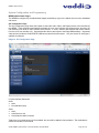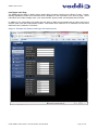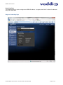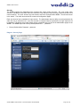
1
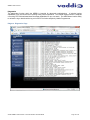
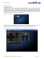
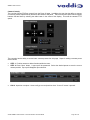
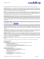
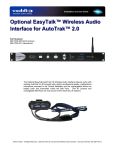
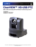
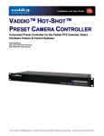
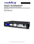
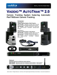
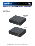
Installation and User Guide VADDIO™ WEBBi™ Web based Room Control System for Vaddio EasyUSB™ Tools Part Numbers: 999-8700-000: WEBBi Web Controller (North America) 999-8700-001: WEBBi Web Controller (International) © 2012 Vaddio - All Rights Reserved. Vaddio WEBBi - Document Number 342-0445 Rev A WEBBi - Web Controller Inside Front Cover - Blank Vaddio WEBBi - Web Controller - Document Number 342-0445 Rev B Page 2 of 24 WEBBi - Web Controller TableofContents Overview ................................................................................................................................................................................................................. 4 Unpacking ............................................................................................................................................................................................................... 5 WEBBi - Part Number 999-8700-000 for North America .................................................................................................................................... 5 WEBBi - Part Number 999-8700-001 for International ....................................................................................................................................... 5 Equipment Descriptions and Call-outs .................................................................................................................................................................... 6 Diagram: WEBBi Front Panel........................................................................................................................................................................ 6 Diagram: WEBBi Rear Panel ........................................................................................................................................................................ 6 Connecting the WEBBi............................................................................................................................................................................................ 7 WEBBi System Connection Diagrams................................................................................................................................................................ 7 Diagram: WEBBi with EasyUSB Mixer/Amp and HD-USB PTZ Camera ...................................................................................................... 7 WEBBi with AutoPresenter ................................................................................................................................................................................. 8 Diagram: WEBBi with Multiple Cameras and Auto Presenter ....................................................................................................................... 8 Installation Instructions............................................................................................................................................................................................ 9 WEBBi ................................................................................................................................................................................................................ 9 Diagram: WEBBi Installation Steps ............................................................................................................................................................... 9 System Configuration and Programming .............................................................................................................................................................. 10 WEBBi Administrator Pages ............................................................................................................................................................................. 10 A/V Configuration Page .................................................................................................................................................................................... 10 Diagram: A/V Configuration Page ............................................................................................................................................................... 10 User Button Label Page ................................................................................................................................................................................... 11 Diagram: Example User Button Label Page with AutoPresenter ................................................................................................................ 11 Networking Page .............................................................................................................................................................................................. 12 Diagram: Networking Page ......................................................................................................................................................................... 12 Security ............................................................................................................................................................................................................. 13 Diagram: Security Page .............................................................................................................................................................................. 13 Diagnostics ....................................................................................................................................................................................................... 14 Diagram: Diagnostics Page......................................................................................................................................................................... 14 System .............................................................................................................................................................................................................. 15 Diagram: System Menu............................................................................................................................................................................... 15 User Operations .................................................................................................................................................................................................... 16 Room User Interface (UI) ................................................................................................................................................................................. 16 Diagram: Log-in Screen .............................................................................................................................................................................. 16 Diagram: UI Web Page for EASYUSB Mixer/Amp and ClearVIEW HD-USB PTZ Camera ....................................................................... 16 Diagram: UI Web Page for EasyUSB and AutoPresenter .......................................................................................................................... 17 Audio Controls .................................................................................................................................................................................................. 17 Camera Controls .............................................................................................................................................................................................. 18 AutoPresenter Controls .................................................................................................................................................................................... 19 Warranty Information:............................................................................................................................................................................................ 20 Technical Specifications........................................................................................................................................................................................ 21 Customer Support Contact Information ........................................................................................................................................................... 21 Appendix 1- Connectors Pin Outs ......................................................................................................................................................................... 23 Vaddio WEBBi - Web Controller - Document Number 342-0445 Rev B Page 3 of 24 WEBBi - Web Controller Overview The WEBBi is an inexpensive room A/V control system for use with the EasyUSB Tools product family. The WEBBi is a complete room control system for the EasyUSB™ Tools devices including EasyMic™ MicPODs, EasyUSB Mixer/Amp, ClearVIEW™ HD-USB PTZ Camera and AutoPresenter™ products. Simply connect to the WEBBi’s web server with a PC browser and control the room’s camera, display and audio. The WEBBi control functions are intended to be used with any device equipped with a web browser and internet access providing an intuitive user interface for control of the room audio and video devices. An embedded web server serves the room’s user interface control page to a connected client like a PC, tablet, or smartphone. The room UI includes interactive user controls for room audio volume, microphone mute, camera PTZ and preset execution, and LCD display power control via IR probe. The WEBBi is easily configured from administration pages allowing the installer the flexibility to select Vaddio EasyUSB devices used in application, communication interfaces, and button labeling. Intended Use: Before operating the device, please read the entire manual thoroughly. The system was designed, built and tested for use indoors, and with the provided power supply and cabling. The use of a power supply other than the one provided or outdoor operation has not been tested and could damage the device and/or create a potentially unsafe operating condition. Important Safeguards: Read and understand all instructions before using. Do not operate any device if it has been dropped or damaged. In this case, a Vaddio technician must examine the product before operating. To reduce the risk of electric shock, do not immerse in water or other liquids and avoid extremely humid conditions. Do not connect Ethernet or Power over Ethernet (POE) cables directly to the RJ-45 ports on the device as damage may result. Use only the power supply provided with the system. Use of any unauthorized power supply will void any and all warranties. Please do not use “pass-thru” type RJ-45 connectors. These pass-thru type connectors do not work well for professional installations and can be the cause of intermittent connections which can result in the RS-232 control line failing and locking up. For best results please use standard RJ-45 connectors and test all cables for proper pin-outs prior to use. Save These Instructions: The information contained in this manual will help you install and operate your product. If these instructions are misplaced, Vaddio keeps copies of Specifications, Installation and User Guides and most pertinent product drawings for the Vaddio product line on the Vaddio website. These documents can be downloaded from www.vaddio.com free of charge. Vaddio WEBBi - Web Controller - Document Number 342-0445 Rev B Page 4 of 24 WEBBi - Web Controller Unpacking All components within the shipping box are individually packaged as described in the sections below. Carefully remove all parts included in the individual packaging. WEBBi - Part Number 999-8700-000 for North America North American Pack-out includes: One (1) WEBBi Web Controller Appliance One (1) 12 VDC 1.0 Amp PowerRite™ Switching Power Supply One (1) Power Cord for North America One (1) 6’ (1.83m) USB Type A to Type B Cable (Black) WEBBi - Part Number 999-8700-001 for International International Pack-out includes: One (1) WEBBi Web Controller Appliance One (1) 12 VDC 1.0 Amp PowerRite Switching Power Supply One (1) Euro Power Cord One (1) UK Power Cord One (1) 6’ (1.83m) USB Type A to Type B Cable (Black) Option: Rack Mounting Kit The rack kit provides a method for the WEBBi to be installed in a 1-RU space within a rack. The rack kit includes two rack ears (one long and one short). The rack ears are mounted in the sides of the WEBBi enclosure using the existing screws included on the device. Rack Kit Part Number 998-6000-004 Vaddio WEBBi - Web Controller - Document Number 342-0445 Rev B Page 5 of 24 WEBBi - Web Controller Equipment Descriptions and Call-outs Diagram: WEBBi Front Panel ➋ ➊ ➍ ➌ ➎ 1) Recessed Power/Reset Button: Resets and reboots the WEBBi device with push button activation. 2) LCD Display: Scrolls current IP Address across the screen when the unit is plugged in. 3) RS-232 LED Indicators: Blue LED indicators for both the Audio & Video port connection to the EasyUSB Tool devices. LED will flash when communication activity is detected with the device under control. 4) Network LED Indicators: LEDs will flash blue to indicate detection of Ethernet activity between web server and attached browser client. 5) Power LED Indicator: This LED will illuminate blue when power is detected. Diagram: WEBBi Rear Panel ➊ ➋ ➌ ➍ ➎ ➏ ➐ 1) Power Connector: 5.5mm OD x 2.5mm ID coaxial connector, positive center for supplying power to device. Use with 12 VDC, 1.0A power supply included in package only. 2) DIP Switches: Used to reset device to factory defaults. Setting all dip switches to the off-position will reset the unit to factory defaults on the next power cycle. User will lose all programmed configurations on the factory default operation. 3) Audio Control: RJ-45 connector with RS-232 functionality (see appendix for pin-out). RS-232 Control port for use with Vaddio EasyUSB Mixer/Amp. . 4) Video Control: RJ-45 connector with RS-232 functionality (see appendix for pin-out). RS-232 Control port for use with Vaddio HD-USB PTZ Camera or AutoPresenter. 5) USB: For future use. 6) Network: 10/100 Ethernet port for connection to the Local Area Network. 7) IR Port: For future use. Vaddio WEBBi - Web Controller - Document Number 342-0445 Rev B Page 6 of 24 WEBBi - Web Controller Connecting the WEBBi WEBBi System Connection Diagrams The WEBBi control system is for use with Vaddio A/V equipment providing a plug & play connection scheme using standard RJ-45 connectors and CAT-5 cable for the physical connection between devices. Supported devices include the EasyUSB Mixer/Amp, ClearVIEW HD-USB PTZ Camera, and AutoPresenter products. The applications below depict common applications that can be supported with the WEBBi control system. WEBBi Configuration with EasyUSB and HD-USB Camera Below are the connections for enabling web control of an EasyTalk Audio solution and an HD-USB PTZ Camera. Web pages will be served up via the Ethernet connection. Diagram: WEBBi with EasyUSB Mixer/Amp and HD-USB PTZ Camera Two (2) EasyTalk Bose DS16F Ceiling Speakers ClearVIEW HD-USB PTZ Camera USB 2.0 Audio with UAC Drivers EasyUSB Mixer/AMP Rear Panel RS-232 RS-232 USB 2.0 Video with UVC Drivers RS-232 for Audio Device Two (2) EasyMic MicPOD Table Mics RS-232 for Video Device PC with UC Client and WEBBi control web Page WEBBi Ethernet Ethernet Vaddio WEBBi - Web Controller - Document Number 342-0445 Rev B Page 7 of 24 WEBBi - Web Controller WEBBi with AutoPresenter The WEBBi can be used with the AutoPresenter providing camera controls, video input selection, preset activation, and PIP controls from the embedded Web Pages. The physical connection is a simple RJ-45 with CAT-5 cable along with a 9-pin (DE-9 or DB-9 for the conventionalists) to RJ-45 adapter for use on the AutoPresenter RS-232 back panel connector. The WEBBi will serve up web pages via the network connection. Diagram: WEBBi with Multiple Cameras and Auto Presenter WallVIEW HD-20’s with CONCEAL Mounts AV Bridge - Audio and Video Encoder HD Video IN USB 2.0 Video OUT EasyUSB Mixer/Amp With Mics and Speakers RS-232 for Video Device RS-232 for Audio WEBBi USB 2.0 Audio with UAC Drivers PC with UC Client and WEBBi control web Page Ethernet Ethernet USB 2.0 - Video with UVC Drivers Vaddio WEBBi - Web Controller - Document Number 342-0445 Rev B Page 8 of 24 WEBBi - Web Controller Installation Instructions WEBBi Locate the WEBBi near a Network jack for control over the Local Area Network. Follow the steps below to install all of the devices. Diagram: WEBBi Installation Steps WEBBI - Web Controller 12 VDC, 1.0 Amp Power Supply EasyUSB Mixer/Amp Cessna 174 Not Included HD-USB PTZ Camera 1 4 2 PC 3 STEP 1: Plug 12 VDC, 1.0 Amp power supply included in package into the WEBBi. Power LED on the front panel should light solid blue when powered. STEP 2: Connect RJ-45 using CAT-5 or better cable between WEBBi audio control RS-232 RJ-45 jack and EasyUSB Mixer/Amp RS-232 RJ-45 jack for audio control via web pages. STEP 3: Connect RJ-45 using CAT-5 or better cable between WEBBi video control RS-232 RJ-45 jack and ClearVIEW HD-USB PTZ Camera (RJ-45 jack) or AutoPresenter RS-232 9-pin jack. STEP 4: Connect WEBBi to the LAN for serving web pages over an IP address configured by the administrator**. **Note: The WEBBi can be directly connected to a PC using a network crossover cable for initial installation configuration purposes. In absence of a DHCP server in this scenario, the WEBBi will default to a static IP address of 169.254.1.1. Once connected with the Network crossover cable, the installer can use this static IP address in the browser to navigate to the web pages**. Vaddio WEBBi - Web Controller - Document Number 342-0445 Rev B Page 9 of 24 WEBBi - Web Controller System Configuration and Programming WEBBi Administrator Pages The WEBBi is configured by the administrator pages accessible by log-in to the Admin account on the embedded web server. A/V Configuration Page The A/V Configuration page allows the installer to select the Audio, Video, and Display device to be controlled by the WEBBi. These selections automatically generate the room user interface web pages that are served to the user allowing room audio & video controls of the devices. A “none” selection will eliminate that control feature from the room user interface (UI). Supported audio devices are limited to the EasyUSB Mixer/Amp. Supported video devices include the ClearVIEW HD-USB camera and the AutoPresenter. Only one device for each type is available for selection. Diagram: A/V Configuration Page UI (user interface) Selections: Audio: None EasyUSB Mixer/Amp Video: None, AutoPresenter and ClearVIEW HD‐USB PTZ Camera Today there is a limited amount of UI’s available, but more will be added in future releases. The combinations will be covered later in the manual. Vaddio WEBBi - Web Controller - Document Number 342-0445 Rev B Page 10 of 24 WEBBi - Web Controller User Button Label Page The WEBBi has the ability to define custom button labels for select functions on the Room UI page. Custom labeling capabilities include room information that is displayed on the top header of the room UI page. Room information can include company name, room name/number, phone number, and help desk phone number. In addition to the room labels, the installer has the ability to label camera presets and the video source input selection when used with AutoPresenter product. Most labels are a maximum of 10 characters, but the Room labels can have a maximum of 32 letters. Diagram: Example User Button Label Page with AutoPresenter Vaddio WEBBi - Web Controller - Document Number 342-0445 Rev B Page 11 of 24 WEBBi - Web Controller Networking Page The Networking page is used to configure the WEBBi IP address. It supports either DHCP or Static IP addresses along with a Host name. . Diagram: Networking Page Vaddio WEBBi - Web Controller - Document Number 342-0445 Rev B Page 12 of 24 WEBBi - Web Controller Security The WEBBi supports two independent user accounts with varying levels of access. The “user” (lower case) account is intended for end-users within the conference room that only require access to audio and video room control functions. The ‘User’ account only has access to the Room UI pages within WEBBi. The second account is the ‘admin’. The admin account has full access to all configuration pages. Each user account has a password for login security. The administrator has the ability to set the passwords for either the user or admin account. If the user account is configured without a password, the login sequence will be bypassed. The admin account will always require a password entry for login to the administrator pages on the WEBBi. The WEBBi ships with a factory default password of….. ‘password’. Factory Default Admin Password: password Diagram: Security Page Vaddio WEBBi - Web Controller - Document Number 342-0445 Rev B Page 13 of 24 WEBBi - Web Controller Diagnostics The diagnostics function within the WEBBi is intended for advanced troubleshooting. It includes logging capabilities of key events and error reporting during normal operations. The internal logging function is setup as a revolving FIFO with estimated internal storage capabilities for up to one week. The administrator has the ability to refresh the log or download the Log to a local PC for further analysis by Vaddio Programmers. Diagram: Diagnostics Page Vaddio WEBBi - Web Controller - Document Number 342-0445 Rev B Page 14 of 24 WEBBi - Web Controller System The system menu is intended for firmware update operations associated with the WEBBi. The administrator can select the new firmware file from a local or network drive. The ‘begin firmware update’ button is actuated once desired firmware file is selected. The update process will include user notification of status. Diagram: System Menu Help: The help menu provides general information on the WEBBi and is intended to assist the installer in configuration and programming of the WEBBi. The help menu also includes information on the current firmware release loaded on the device. Camera Controls: The Camera Controls page allows the installer to position the PTZ camera and store camera presets within the Administrative pages. The camera controls page will mimic that of the Room UI page presented to the user after installation. Logout: The logout menu function exists from the administrator pages within the web server. Factory Default: The WEBBi can be restored to factory defaults with the dip switches on the rear of the device. Process for defaulting WEBBi to factory settings is: Step 1: Place all dip switches to the off position (down). Warning: Current settings will be erased. Step 2: Press Reset on the front panel of the WEBBi. Device will reboot to factory settings. Vaddio WEBBi - Web Controller - Document Number 342-0445 Rev B Page 15 of 24 WEBBi - Web Controller User Operations Room User Interface (UI) The WEBBi web server includes a graphical user interface page intended for end-user operations of the Vaddio EasyUSB Tools product family. The UI page includes all audio and video controls needed by the user during a meeting or conference call. The user can access the Room UI page by opening a browser on a PC or tablet and typing in the URL or IP address of the WEBBi. If a user password was configured by the administrator, a login screen will be presented to the user. If a user password was not programmed, the Room UI page with automatically be served upon connection to the URL address. Diagram: Log-in Screen WEBBi automatically generates Room UI webpages based upon the EasyUSB Tools products connected. The following UI screen Shot is for the EasyUSB Mixer/Amp and the ClearVIEW HD-USB PTZ Camera. Diagram: UI Web Page for EASYUSB Mixer/Amp and ClearVIEW HD-USB PTZ Camera Vaddio WEBBi - Web Controller - Document Number 342-0445 Rev B Page 16 of 24 WEBBi - Web Controller Diagram: UI Web Page for EasyUSB and AutoPresenter The video input buttons were added on the bottom of the page and the PIP functions were added to the top of the page in order to better control the AutoPresenter’s key features. Audio Controls The user audio controls include microphone mute, microphone gain, and speaker volume controls. The microphone mute applies to all EasyMic devices in a global fashion. The microphone icon changes visual representation (RED with NOT ICON) to depict the mute state. Microphone gain can be modified with the up and down buttons. This gain represents the USB audio level (RECORD) being set to the Host PC. The loudspeaker volume can be modified with the second set of Up/Down buttons. The Volume change applies to the EasyUSB Mixer/Amp loudspeakers and Line Outputs. Vaddio WEBBi - Web Controller - Document Number 342-0445 Rev B Page 17 of 24 WEBBi - Web Controller Camera Controls The user has full Pan/Tilt/Zoom controls from the Room UI page. In addition, the user has the ability to execute six camera presets represented by buttons at the bottom of the panel. Pan/Tilt and Zoom speed can be toggled between fast and slow by selecting the radio button in the center of the display. This sets the camera’s PTZ speed. The user also has the ability to set and store camera presets from this page. Steps for setting a camera preset are as follows: STEP 1: Position camera to desired location within the room. STEP 2: Press ‘Store’ button. A pop-up will be presented. Select the desired preset to store the current camera position. Pop-up will disappear upon selection. STEP 3: Operation complete. Camera will go to stored position when “Preset 4” button is pressed. Vaddio WEBBi - Web Controller - Document Number 342-0445 Rev B Page 18 of 24 WEBBi - Web Controller AutoPresenter Controls Additional control features will be presented to the user when WEBBi is used with the AutoPresenter. Controls will include Video Inputs and Picture-In-Picture. Video Input Select allows the user to switch between up to 5 additional video source inputs connected to the AutoPresenter. If the selected Video Input source is a Vaddio PTZ camera, the PTZ controls will be switched to that source allowing camera controls from the Room UI. The PIP Controls provides the user with the ability to create a mosaic image from two independent video input sources. Steps for creation and operations of the PIP function are: STEP 1: Press the PIP On/Off Button STEP 2: Upon turning the PIP on, a pop-up will be presented allowing the user to select the second video source to be used for the PIP output. Once selected a PIP mosaic output will be created with the current video input source and the selected PIP video input source. STEP 3: Additional PIP controls allow the user to format the video output as desired. PIP control functions include: Move will position the PIP video input into one of the five (5) positions; four corners and lower center of the main video image. Pushing the button will toggle the PIP image between the five locations. Resize changes the PIP image size. Pushing the button will toggle between the available three (3) images sizes. Swap will automatically switch the main video input and the PIP video input within the mosaic image. Vaddio WEBBi - Web Controller - Document Number 342-0445 Rev B Page 19 of 24 WEBBi - Web Controller Warranty Information: (See Vaddio Warranty, Service and Return Policies posted on vaddio.com for complete details): Hardware* Warranty: One year limited warranty on all parts. Vaddio warrants this product against defects in materials and workmanship for a period of one year from the day of purchase from Vaddio. If Vaddio receives notice of such defects during the warranty period, they will, at their option, repair or replace products that prove to be defective. Please see Vaddio’s Service Terms and Conditions at vaddio.com for specific details and policies. Exclusions: The above warranty shall not apply to defects resulting from: improper or inadequate maintenance by the customer, customer applied software or interfacing, unauthorized modifications or misuse, operation outside the normal environmental specifications for the product, use of the incorrect power supply, improper installation (plugging things in wrong), improper extension of the power supply cable or improper site operation and maintenance. Vaddio Customer Service: Vaddio will test, repair, or replace the product or products without charge if the unit is under warranty and is found to be defective. If the product is out of warranty, Vaddio will test then repair the product or products. The cost of parts and labor charge will be estimated by a technician and confirmed by the customer prior to repair. All components must be returned for testing as a complete unit. Vaddio will not accept responsibility for shipment after it has left the premises. Vaddio will only advance replace out of box failures or random equipment failures up to 30 days after the purchase date (not the install date). Vaddio Technical Support: Vaddio technicians will determine and discuss with the customer the criteria for repair costs and/or replacement. Vaddio Technical Support can be contacted through one of the following resources: e-mail support at [email protected] or online at www.vaddio.com. Return Material Authorization (RMA) Number: Before returning a product for repair or replacement, request an RMA from Vaddio’s technical support. Provide a technician with a return phone number, e-mail address, shipping address, and product serial numbers and describe the reason for repairs or returns as well as the date of purchase and proof of purchase. Include your assigned RMA number in all correspondence with Vaddio. Write your assigned RMA number on the clearly on the shipping label when returning the product. All products returned for credit are subject to a restocking charge without exception. Voided Warranty: The warranty does not apply if the original serial number has been removed or if the product has been disassembled or damaged through misuse, accident, modifications, or unauthorized repair. Cutting the power supply cable on the secondary side (low voltage side) to extend the power to the device voids the warranty for that device. Shipping and Handling: Vaddio will not pay for inbound shipping transportation or insurance charges or accept any responsibility for laws and ordinances from inbound transit. Vaddio will pay for outbound shipping, transportation, and insurance charges for all items under warranty but will not assume responsibility for loss and/or damage by the outbound freight carrier. If the return shipment appears damaged, retain the original boxes and packing material for inspection by the carrier. Contact your carrier immediately. Products Not Under Warranty: Payment arrangements are required before outbound shipment for all out of warranty products. *Vaddio manufactures its hardware products from parts and components that are new or equivalent to new in accordance with industry standard practices. Other General Information: Care and Cleaning Do not attempt to take this product apart at any time. There are no user-serviceable components inside. Do not spill liquids in the product Keep this device away from food and liquid For smears or smudges on the product, wipe with a clean, soft cloth Use a lens cleaner on the lens, but no lens is on the WEBBi, so it’s one less thing to remember. Do not use any abrasive chemicals. Operating and Storage Conditions: Do not store or operate the device under the following conditions: Temperatures above 40°C (104°F) or temperatures below 0°C (32°F) High humidity, condensing or wet environments In Bear Caves and Cliff Dwellings In inclement weather Dry environments with an excess of static discharge In an loosely organized system of nominally oxygenated amino acids Under severe vibration Vaddio WEBBi - Web Controller - Document Number 342-0445 Rev B Page 20 of 24 WEBBi - Web Controller Technical Specifications WEBBi Part Numbers WEBBi 999-8700-000 (North America) WEBBi 999-8700-001 (International) USB Port Future Network Port Connector: RJ-45 10/100 Base-T Audio Control Connector: RJ 45 Port Interface: RS-232 ,38.4K baud Max Distance: 100’ (30.48m) Video Control Connector: RJ-45 Port Interface: RS-232, 9600 Baud Max Distance: 100’ (30.48m) IR Port Future Settings 6-Position Dip Switch (Factory Default) Power Supply 5.5mm OD x 2.5mm ID Coax Connector 12 VDC, 1.0 Amp, Auto-switching General Information Operating 32° to 104° F (0° to 40° C) Temp Power < 12 watts Consumption Dimensions 8.375” ( 212.73mm) W x 6.0” (152.4mm) x 1.72” ( 43.688mm) H Weight 1.4 lbs (0.635Kg) Customer Support Contact Information Address: Vaddio 9433 Science Center Drive New Hope, MN 55428 Email: [email protected] Website: www.vaddio.com Toll Free: +1 (800) 572-2011 Phone: +1 (763) 971-4400 Fax: +1 (763) 971-4464 Vaddio WEBBi - Web Controller - Document Number 342-0445 Rev B Page 21 of 24 WEBBi - Web Controller Compliance and CE Declaration of Conformity: WEBBi - Web Controller Compliance testing was performed to the following regulations: FCC Part15, Sections 15.107, 15.109 Subpart B Class A ICES-003 ISSUE 4, 2004 Class A EN55022 A1 2007 Class A EMC Directive 2004/108/EC Class A IEC 60950-1:2005 (2nd Edition); Am 1:2009 Class A EN 60950-1:2006+A11:2009+A1:2010+A12:2011 Class A FCC Part 15 Compliance This equipment has been tested and found to comply with the limits for a Class A digital device, pursuant to Part 15, Subpart B, of the FCC Rules. These limits are designed to provide reasonable protection against harmful interference when the equipment is operated in a commercial environment. This equipment generates, uses, and can radiate radio frequency energy and, if not installed and used in accordance with the instruction manual, may cause harmful interference to radio communications. Operation of this equipment in a residential area is likely to cause harmful interference in which case the user will be required to correct the interference at his/her own expense. Operation is subject to the following two conditions: (1) This device may not cause interference, and (2) This device must accept any interference including interference that may cause undesired operation of the device. Changes or modifications not expressly approved by Vaddio can affect emission compliance and could void the user’s authority to operate this equipment. ICES-003 Compliance ICES-003, Issue 4: 2004 This digital apparatus does not exceed the Class A limits for radio noise emissions from digital apparatus set out in the Radio Interference Regulations of the Canadian Department of Communications. Le présent appareil numérique n’emet pas de bruits radioélectriques dépassant les limites applicables aux appareils numeriques de la classe B préscrites dans le Règlement sur le brouillage radioélectrique édicte par le ministère des Communications du Canada. European Compliance This product has been evaluated for Electromagnetic Compatibility under the EMC Directive for Emissions and Immunity and meets the requirements for a Class A digital device. In a domestic environment this product may cause radio interference in which case the user may be required to take adequate measures. Standard(s) To Which Conformity Is Declared: EMC Directive 2004/108/EC EN55024/A2:2003 Information Technology Equipment Immunity Characteristics Limits and Methods of Measurement EN 61000-4-2: 1995 + Amendments A1: 1998 + A2: 2001 EN 61000-4-3: 2006 + A1: 2008 EN 61000-4-4: 2004 + Corrigendum 2006 EN 61000-4-5: 2006 EN 61000-4-6: 2009 EN 61000-4-8: 2010 EN 61000-4-11: Second Edition: 2004 IEC 60950-1:2005 (2nd Edition); Am 1:2009 EN 60950-1:2006+A11:2009+A1:2010+A12:2011 Vaddio WEBBi - Web Controller - Document Number 342-0445 Rev B Electrostatic Discharge Radiated Immunity Electrical Fast Transients Surge Immunity Conducted Immunity Power Frequency Magnetic Field Voltage Dips, Interrupts and Fluctuations Information technology equipment - Safety Information technology equipment - Safety Page 22 of 24 WEBBi - Web Controller Appendix 1- Connectors Pin Outs Audio Control Port (RS-232) on WEBBi Baud Rate: 36.4 kbps Pin # 1 2 3 4 5 6 7* 8* Audio Control Port (RS-232) Unused Unused Unused Unused Unused GRD TXD RXD Video Control Port (RS-232) on WEBBi Baud Rate: 9600 kbps Pin # 1 2 3 4 5 6 7 8 Video Control Port (RS-232) Unused Unused Unused Unused Unused GRD TXD RXD Vaddio WEBBi - Web Controller - Document Number 342-0445 Rev B Page 23 of 24 WEBBi - Web Controller 9433 Science Center Drive, Minneapolis, MN 55428 Toll Free: 800-572-2011 ▪ Phone: 763-971-4400 ▪ FAX: 763-971-4464 www.vaddio.com ©2012 Vaddio - All Rights Reserved. Reproduction in whole or in part without written permission is prohibited. Specifications and pricing are subject to change without notice. Vaddio, ClearVIEW, WEBBi, EZCamera, EasyTalk, EasyMic, EasyUSB, AutoPresenter and PowerRite are trademarks of Vaddio. All other trademarks are property of their respective owners. Document 342-0445 Rev. B Vaddio WEBBi - Web Controller - Document Number 342-0445 Rev B Page 24 of 24