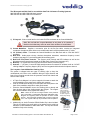
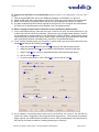
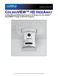
1
INSTALLATION AND USERS GUIDE ™ VADDIO™ AUTOTRAK™ 2.0 Camera Tracking System featuring Automatic Pan/Tilt/Zoom Camera Tracking Part Numbers: AutoTrak 2.0 Camera Tracking System: North America 999-7250-000: AutoTrak 2.0-Dual HD-18 Kit with Quick-Connect DVI/HDMI Interface-North America 999-7260-000: AutoTrak 2.0-HD-18 & HD-20 Kit with Quick-Connect DVI/HDMI Interface-North America AutoTrak 2.0 Camera Tracking System: International 999-7250-001: AutoTrak 2.0-Dual HD-18 Kit with Quick-Connect DVI/HDMI Interface-International 999-7260-001: AutoTrak 2.0-HD-18 & HD-20 Kit with Quick-Connect DVI/HDMI InterfaceInternational Optional: EasyTalk AutoTrak 2.0 Wireless Audio Interface: 998-7230-000: EasyTalk AutoTrak 2.0 Wireless Audio Interface - North America 998-7230-001: EasyTalk AutoTrak 2.0 Wireless Audio Interface - International ©2012 Vaddio - All Rights Reserved. AutoTrak 2.0 with Optional EasyTalk Wireless Audio Interface - Document 342-0382 Rev. B AutoTrak 2.0 Camera Tracking System Inside Front Cover - Blank Inside Front Cover - Blank AutoTrak 2.0 Camera Tracking System - Document Number 342-0382 Rev. B Page 2 of 52 AutoTrak 2.0 Camera Tracking System AutoTrak 2.0 System Overview The AutoTrak 2.0 System is an IR tracking system that consists of an IR lanyard attached to a rechargeable Lithium Ion Belt Pack that is worn by a presenter or instructor. Within the lanyard’s cloth cover, there are fifteen (15) 850nm wavelength IR LEDs on a flat flex circuit that emit IR light that is tracked by a HD-18 PTZ IR Reference Camera with special IR filters. The IR position is relayed to the AutoTrak 2.0 CPU which in turn controls the HD-18 PTZ (or the HD-20 PTZ) Tracking Camera which follows the presenter and keeps the presenter framed in the camera shot throughout the presentation environment. The AutoTrak 2.0 System is designed to integrate with the optional EasyTalk AutoTrak 2.0 Wireless Audio System. The EasyTalk AutoTrak 2.0 Wireless Audio System includes a HD wireless receiver that receives the HD wireless microphone audio transmitted from the AutoTrak 2.0 IR Lanyard and Belt Pack. It also provides audio outputs for connection to an audio amplifier/speaker system or a video conference system. It includes a USB output that can directly connect to a PC USB port which will provide connection of the microphone and room speaker audio for use with Unified Communication clients such as Skype, Microsoft Lync, Google+ and others. AutoTrak 2.0, 999-7250-000 Dual HD-18 PTZ Cameras AutoTrak 2.0, 999-7260-000 HD-18 PTZ IR Reference and HD-20 PTZ Tracking Camera There are two versions of AutoTrak 2.0: AutoTrak 2.0 Dual HD-18 999-7250-000 North America 999-7250-001 International Includes: One (1) HD-18 PTZ IR Reference Camera and one (1) HD-18 Tracking Camera AutoTrak 2.0 HD-18/HD-20 999-7260-000 North America 999-7260-001 International Includes: One (1) HD-18 PTZ IR Reference Camera and one (1) HD-20 PTZ Tracking Camera The HD-18 and HD-20 cameras use the Vaddio Quick-Connect DVI/HDMI Interface to provide Cat-5e cabling systems for ease of set up and installation. The system can be permanently installed or configured as a cart system for portability and ease of positioning in the largest of lecture halls. Each system includes a dual camera mount which can be wall mounted or mounted on top of the Vaddio Edge series video carts. The optimum operating range or the system (from the IR Lanyard to the IR Reference camera) is between 12’ (3.65m) and up to 40’ (12.2m). System positioning is critical for proper and consistent operation. The AutoTrak 2.0 can be installed as a standalone system or can be used in conjunction with myriad Vaddio Presenter controlled solutions including AutoPresenter™, PresenterPOD™, ControlVIEW XHD™, TouchVIEW™, AutoVIEW™ IR, StepVIEW™ Mats, MicVIEW™ and the Vaddio Squiggle Video Whiteboard. As an added benefit, once the AutoTrak 2.0 system is configured the Mouse, Keyboard and Monitor I/O devices can be removed from the system to ensure the system isn’t subject to unauthorized modification. Intended Use: Before operating the device, please read the entire manual thoroughly. The system was designed, built and tested for use indoors, and with the provided power supply and cabling. The use of a power supply other than the one provided or outdoor operation has not been tested and could damage the device and/or create a potentially unsafe operating condition. AutoTrak 2.0 Camera Tracking System - Document Number 342-0382 Rev. B Page 3 of 52 AutoTrak 2.0 Camera Tracking System Important Safeguards: Read and understand all instructions before using. Do not operate any device if it has been dropped or damaged. In this case, a Vaddio technician must examine the product before operating. To reduce the risk of electric shock, do not immerse in water or other liquids and avoid extremely humid conditions. Use only the power supply provided with the system. supply will void any and all warranties. Use of any unauthorized power Please do not use “pass-thru” type RJ-45 connectors. These pass-thru type connectors do not work well for professional installations and can be the cause of intermittent connections which can result in the RS-232 control line failing and locking up, and/or compromising the HSDS™ signals. For best results please use standard RJ-45 connectors and test all cables for proper pin-outs prior to use and connection to Vaddio product. Please treat the AutoTrak 2.0 CPU like a computer. Please shut down the CPU before removing power, like all business computers, or… The AutoTrak 2.0 CPU is a computer running a Linux OS. Please do not remove power from the AutoTrak 2.0 CPU without first shutting the system down, as you would any other business computer. Only after the AutoTrak 2.0 CPU has been shut down, it is safe to remove power. Consistently power cycling the CPU with the Rear Power Switch will eventually wreak havoc with the AutoTrak 2.0 CPU and cause non-warrantable harm. Failure to adhere to this warning will void the product warranty. Save These Instructions: The information contained in this manual will help you install and operate your product. If these instructions are misplaced, Vaddio keeps copies of Specifications, Installation and User Guides and most pertinent product drawings for the Vaddio product line on the Vaddio website. These documents can be downloaded from www.vaddio.com free. UNPACKING: Carefully remove all of the parts for the AutoTrak 2.0 999-7250-000 Dual HD-18 Kit with Quick Connect DVI/HDMI Interface (North America Only) packaging: One (1) AutoTrak 2.0 CPU (closed system preloaded with AutoTrak 2.0 software and video card) One (1) AC Cord Set for AutoTrak 2.0 CPU One (1) PS/2 Keyboard and PS/2 Mouse One (1) IR and Audio Lanyard with attached cable with 5-pin mini XLR connector, One (1) Audio-Technica AT8439 Cable Clip to attach Lanyard Central Medallion to clothing One (1) Triple Circle Magnet Kit for attaching the Lanyard Central Medallion to clothing One (1) Belt Pack Unit “BPU” with 1” (1/4 wave) RP-SMA straight antenna and attached belt clip with rechargeable lithium-ion battery pack and 5 VDC USB charging power supply for North America One (1) USB Type A-Male to micro-B-Male Charging Cable One (1) Vaddio PowerRite 12 VDC, 1A Switching Power Supply with North American Power Cord One (1) AutoTrak POD Kit (for presets and rescan) and Manual (in separate box) AutoTrak 2.0-Dual HD-18 Kit: One (1) *HD-18 PTZ Camera with AutoTrak 2.0 Software preloaded - Tracking Camera One (1) Quick-Connect DVI/HDMI SR Interface (998-1105-018) for Tracking Camera One (1) 24VDC, 2A, Switching Power Supply with North American Power Cord One (1) *HD-18 PTZ Camera with AutoTrak 2.0 Software preloaded – IR Reference Camera One (1) 37mm female lens ring adapter, One (1) 37mm to 58mm adapter ring, One (1) 58mm polarizing filter, One (1) 58mm band-pass IR filter, all parts adapters and filters attached to HD-18 Camera One (1) AutoTrak 2.0 Quick-Connect Box (998-1105-020) One (1) Standard Quick-Connect Box (998-1105-001) One (1) 24VDC, 2A, Switching Power Supply with North American Power Cord One (1) 18”/45.8cm Video Cable (BNC to RCA) One (1) 12”/30.48cm Cat 5e Patch Cable One (1) 998-2100-000 - Vaddio IR Remote & Manual (2-AAA batteries not included) One (1) **535-2000-233 Stacked Gusseted Mount for two (2) HD-18 and Mounting Hardware Three (3) 998-1001-232 Control Adapters One (1) 998-7200-232 Control Adapter for use with the AutoPresenter - (Only needed when used with the AutoPresenter for Tracking Camera PTZ Presets) Documentation and Manuals (Document Number (342-0382) For the 999-7260-000 System¨ Start with the 999-7250-000 System Remove: One (1) *AutoTrak HD-18 PTZ Camera with AutoTrak 2.0 Software preloaded - Tracking Camera Add: One (1) *AutoTrak HD-20 PTZ Camera with AutoTrak 2.0 Software preloaded - Tracking Camera AutoTrak 2.0 Camera Tracking System - Document Number 342-0382 Rev. B Page 4 of 52 AutoTrak 2.0 Camera Tracking System UNPACKING: Carefully remove all of the parts for the AutoTrak 2.0 999-7250-001 (Int’l) Dual HD-18 Kit with Quick Connect DVI/HDMI Interface) packaging: One (1) AutoTrak 2.0 CPU (closed system preloaded with AutoTrak 2.0 software and video card) One (1) Euro Power Cord for AutoTrak 2.0 CPU One (1) UK Power Cord for AutoTrak 2.0 CPU One (1) PS/2 Keyboard and PS/2 Mouse One (1) IR and Audio Lanyard with attached cable with 5-pin mini XLR connector One (1) Audio-Technica AT8439 Cable Clip to attach Lanyard Central Medallion to clothing One (1) Triple Circle Magnet Kit for attaching the Lanyard Central Medallion to clothing One (1) Belt Pack Unit “BPU” with 1” (1/4 wave) RP-SMA straight antenna and attached belt clip with rechargeable lithium ion battery pack One (1) 5 VDC USB Charging Supply for Europe One (1) 5 VDC USB Charging Supply for UK One (1) USB Type A-Male to micro-B-Male Charging Cable One (1) Vaddio PowerRite 12 VDC, 1A Switching Power Supply One (1) Euro Power Cord One (1) UK Power Cord One (1) AutoTrak POD Kit (for presets and rescan) and Manual (in separate box) AutoTrak 2.0-Dual HD-18 Kit: One (1) *HD-18 PTZ Camera with AutoTrak 2.0 Software preloaded - Tracking Camera One (1) Quick-Connect SR Interface (998-1105-016) for Tracking Camera One (1) 24VDC, 2A, Switching Power Supply One (1) Euro Power Cord One (1) UK Power Cord One (1) *HD-18 PTZ Camera with AutoTrak 2.0 Software preloaded - IR Reference Camera One (1) 37mm female lens ring adapter, One (1) 37mm to 58mm adapter ring, One (1) 58mm polarizing filter, One (1) 58mm band-pass IR filter, all parts adapters and filters attached to HD-18 Camera One (1) AutoTrak 2.0 Quick-Connect Box (998-1105-020) One (1) Standard Quick-Connect Box (998-1105-001) One (1) 24VDC, 2A, 50/60Hz 110-240V Switching Power Supply (451-2000-0024) One (1) Euro Power Cord One (1) UK Power Cord One (1) 18”/45.8cm Video Cable (BNC to RCA) One (1) 12”/30.48cm Cat 5e Patch Cable One (1) 998-2100-000 - Vaddio IR Remote & Manual (2-AAA batteries not included) One (1) **535-2000-233 Stacked Gusseted Mount for two (2) HD-18 and Mounting Hardware Three (3) 998-1001-232 Control Adapters One (1) 998-7200-232 Control Adapter for use with the AutoPresenter - (Only needed when used with the AutoPresenter for Tracking Camera PTZ Presets) Documentation and Manuals (Document Number (342-0382) For the 999-7260-001 System - Start with the 999-7250-001 System Remove: One (1) *HD-18 PTZ Camera with AutoTrak 2.0 Software preloaded - Tracking Camera Add: One (1) *HD-20 PTZ Camera with AutoTrak 2.0 Software preloaded - Tracking Camera *Note 1: The Vaddio HD-18 and HD-20 cameras are preloaded with AutoTrak 2.0 control protocols which differ from the modified VISCA type control codes normally used in the stock HD-18 PTZ Camera. The HD-18 and HD-20 cameras will work with the Vaddio IR Remote but is recommended that the PTZ positions of the camera be set with the AutoTrak 2.0 Software. The HD-18 and HD-20 AutoTrak 2.0 cameras will not work with any other controller other than AutoTrak 2.0 at this time. **Note 2: The stacked camera arrangement is required for the AutoTrak 2.0 software to track properly. AutoTrak 2.0 Camera Tracking System - Document Number 342-0382 Rev. B Page 5 of 52 AutoTrak 2.0 Camera Tracking System AutoTrak 2.0 Components: AutoTrak 2.0 CPU Note: The AutoTrak 2.0 CPU may be subject to change in cosmetics due to the extraordinarily turbulent nature of the PC industry, parts availability and model year upgrades. If changes are made, Vaddio will be certain to make changes in the documentation accordingly. The AutoTrak 2.0 CPU is a 1-RU rack mount computer that will come preloaded with the AutoTrak 2.0 software. The exact specifications are subject to change and any changes that will be made will be in the spirit of product improvement only. The AutoTrak 2.0 CPU uses an Intel® Atom™ Dual Core Processor, Intel Graphics Media Accelerator, 1GB DDR2 Memory, four (4) RS-232 Ports, six (6) USB 2.0 ports, two (2) PS/2 interfaces for keyboard/mouse, 16GB Compact Flash and Video capture card. An important feature: After the AutoTrak 2.0 CPU and software is configured using the mouse, keyboard and monitor, these I/O devices can be removed to prevent any unauthorized access to the system. To reattach the mouse and keyboard, the system will need to be rebooted to recognize these devices. Front Panel Controls of AutoTrak 2.0 Worldwide CPU: ① ② ③ ④ 1) Power Indicator: Illuminates when power in on 2) Hard Drive Activity Indicator: Indicates when solid state drive is active 3) Recessed Reset Switch: A Momentary press of this switch resets the system and prepares the CPU for an orderly shut-down. When the green light blinks, it is ready to be turned off or it is safe to restart (power cycle). 4) USB Ports: Two (2) Front Panel USB Ports Rear Panel of AutoTrak 2.0 Worldwide CPU: ② ④ ⑤ ⑦ ⑩ ① ③ ⑥ ⑧ ⑨ 1) Power Receptacle: IEC60320 C14 for power cable 2) Power Switch: Turns ON/OFF AutoTrak 2.0 CPU NOTE: Do not turn the power off with the power switch on the rear panel or rack power switch unless the computer has been shut down first. Repeated power cycling without shutting down the computer first will cause harm to the system (like all other business computers) and any warranties will be voided. 3) COM PORT 1: RS-232 Port for HD-18 IR Reference Camera 4) COM PORT 2: RS-232 Port for HD-18 Tracking Camera 5) COM PORT 3: Use RS-232 Port 3 when AutoTrak 2.0 is used with the AutoTrak POD or the AutoPresenter 6x1 HD Switcher 6) RGBHV (on DE-15) Output: To setup and view software menus (800 x 600 @ 60Hz) 7) Ethernet Ports: Not used with AutoTrak 2.0 Application 8) USB Ports: Four USB Ports on the back panel for use with Keyboard, Mouse and USB Flash Drive 9) Audio I/O: Not used with AutoTrak 2.0 Application 10) Video Input Port: Plug the HD-18 IR Reference Camera into the center yellow composite video connector Shut Down CPU First AutoTrak 2.0 Camera Tracking System - Document Number 342-0382 Rev. B Page 6 of 52 AutoTrak 2.0 Camera Tracking System The IR Lanyard and Belt Pack for use with the AutoTrak 2.0 Camera Tracking Systems: 999-7250-000 and 999-7260-000 North America 999-7250-001 and 999-7260-001 International ⑤ ⑥ ⑦ ④ ③ ② ① 1) IR Lanyard: Cloth covered flat flex circuit with IR LEDs terminates at the Central Medallion Note: Do not fold the Lanyard Necklace at any time as it contains a flexible circuit that may cease to work if the necklace is hard folded. 2) Central Medallion: Supplies a connection point for the flat flex cable, contains an integrated condenser microphone and a rubber over-molded cable strain relief that attaches the 32” cable. 3) 32” (813mm) Cable: Terminates the Central Medallion to the Belt Pack with a 5-Pin Mini XLR-F connector. 4) Belt Pack: Holds power circuitry, wireless microphone transmitter, transmitter frequency control switches (see pages 6-7) and rechargeable lithium battery pack. 5) Belt Pack Front Panel Controls: The System on/off controls and LED indicator as well as the Microphone on/off controls are located on the Belt Pack Control Panel (see page 6-7). 6) Belt Clip: To clip the Belt Pack on a belt like device that the presenter wears. 7) Antenna: 1” (25.4mm) ¼-wave RP-SMA straight antenna to transmit RF wireless audio at 2.4 GHZ utilizing Adaptive Frequency Hopper (AFH) from the integrated unidirectional microphone element. The Lanyard’s Central Medallion Clothing Clips: The system is shipped with two types of clothing clips to keep the unidirectional mic built-in to the medallion facing the right direction and keep it from flopping around when the presenter moves their hands and arms to make a point. 1. A Triple Circle Magnet is a 2-piece magnetic kit meant to attach the central medallion to the presenter’s clothes with magnets. Peel off the adhesive backing cover and place the metal plate to the back of the medallion and push to make good contact Place the Central Medallion next to the clothing (shirt or dress) and from the back side of the clothing attach the magnet. The magnet will hold the medallion firmly against the clothing. Note: Please do not use the magnet solution if the presenter has a pacemaker or implantable cardioverter-defibrillator (ICD). Magnets can negatively affect the operation of these medical devices. The magnet side is labeled with a caution to warn the user. Use only the Cable Clip for pacemaker and ICD patients 2. Additionally, an Audio-Technica AT8439 Cable Clip is also included. This clip for clothing is a small and is to be attached to the cable just below the central medallion’s cable strain relief. The clip will hold the medallion firmly to the clothing AutoTrak 2.0 Camera Tracking System - Document Number 342-0382 Rev. B Attach metal plate with the adhesive backing to the back of the medallion. Use the triple magnets to attach trough clothing. Attach Cable Clip to a point just below the strain relief. Page 7 of 52 AutoTrak 2.0 Camera Tracking System Belt Pack Control Panel ① ⑤ ② ③ ④ 1) Lanyard Cable Connector (5-pin mini XLR - M): Plug the cable attached to the Lanyard into the mini XLR connector to allow audio to be received by the Belt Pack and for power to be provided to the IR LEDs in the Lanyard. 2) Radio: This LED indicates an active radio link with the EasyTalk AutoTrak 2.0 Wireless Audio Interface. Solid blue LED indicates connection with the AutoTrak 2.0 Wireless Audio Interface. Flashing blue LED indicates radio link has been lost. Note: Radio link operates up to 100 feet line of sight of the AutoTrak 2.0 Wireless Audio Interface. 3) System Power: To use the Belt Pack or IR Lanyard, turn the SYSTEM POWER switch to the on position and the LED will illuminate. Be sure to turn off the SYSTEM POWER switch when the system is not in use to save the battery life. The Rechargeable Lithium Ion Battery Pack provides up to ten (10) hours with full charge. Note: It is highly recommended that the Rechargeable Lithium Ion Battery Pack be fully charged prior to using the Belt Pack for the first time! 4) Microphone ON/OFF: This switch turns the wireless microphone on or off at the Belt Pack allowing the presenter to use an existing room system microphone instead, or for momentary microphone muting. Note: The System Status light on the EasyTalk AutoTrak 2.0 Wireless Audio Interface will light if the microphone signal is detected. If the Microphone is turned off at the Belt Pack, the System Status light will not light. 5) 1” ¼-Wave Antenna: Used to transmit the wireless microphone audio back to the AutoTrak 2.0 Wireless Audio Interface. AutoTrak 2.0 Camera Tracking System - Document Number 342-0382 Rev. B Page 8 of 52 AutoTrak 2.0 Camera Tracking System Belt Pack Views: ① ④ ⑤ ③ ② ⑥ Belt Pack and Battery Compartment: 1) Removable Battery Compartment Cover: To open, carefully press down at the top of the Removable Battery Cover near the center of the small opening and slide the cover downward. To replace the Removable Battery Cover, start sliding the cover on at the bottom of the Battery Pack Compartment and slide cover upward to the top to the small opening until the cover latches in place. 2) Micro-B USB Charging Port: The Belt Pack rechargeable battery can be charged by the micro-B USB connector on the bottom side of the belt pack enclosure. A USB charger is included with the Belt Pack. The Belt Pack can also be recharged by using a micro-B USB to USB adapter which can be connected to a PC or Laptop USB port for recharging. Use only the charging power supply provided. 3) Dip Switches: There are two (2) 4-position dip switches located on the circuit board, SW4 and SW5. They provide configuration settings for Microphone Gain Control, Filtering, Compression and Microphone Filtering and Pairing of the Wireless Belt Pack to the AutoTrak 2.0 Wireless Audio Interface. 4) Rechargeable Lithium Ion Battery: The battery is housed and attached inside the Battery Compartment and under normal use should last up to ten (10) hours when fully charged. 5) Battery Indicator LED: The Battery Indicator LED is located on the bottom of the Belt Pack. When the USB Charger is not connected to the Belt Pack: The Battery Indicator LED will be off when battery power is adequate for the Belt Pack. The Battery Indicator LED will blink Red indicating that the battery power is low and needs to be recharged soon. When the USB Charger is connected to the Belt Pack: The Battery Indicator LED will be Yellow when the battery is charging. The Battery Indicator LED will be Green when the battery is fully charged. Average charging time from dead battery to full charge is 10 hours. 6) Radio Pairing Button SW3: push this button in conjunction with the Pairing button on the front panel of the Optional Wireless Receiver to “pair” the transmitting Belt Pack with the Receiver. AutoTrak 2.0 Camera Tracking System - Document Number 342-0382 Rev. B Page 9 of 52 AutoTrak 2.0 Camera Tracking System Belt Pack Dip Switch Settings: Switch Number 1 2 3 4 1 2 3 4 Dip Switch Function Switch Set 4 Not Used ON/OFF - IR LED’s in Lanyard ON/OFF - Radio in Belt Pack *Turn off when not using Optional EasyTalk Wireless Receiver Clear Pairing (pairing is required for proper operation) Switch Set 5 ON/OFF: ON adds 3dB Gain Boost on Microphone ON/OFF: ON adds 6dB Gain Boost on Microphone ON/OFF: ON adds 9dB Gain Boost on Microphone ON/OFF: Automatic Gain Control Mode SW5 SW4 SW3 Belt Pack Configuration Settings: The Belt Pack has a number of custom settings that can be enabled or disabled for specific applications. These settings can be applied by activating dip switch settings on the two (2) 4-position dip switches SW4 and SW5 located on the Belt Pack Circuit Board. Switch Set 4: SW4: Dip Switch 1 - Not Used SW4: Dip Switch 2 - IR Transmitter: ON enables the IR Transmitter LED’s in the IR Lanyard. OFF disables the IR Transmitters in the Lanyard and the camera tracking will not function. SW4: Dip Switch 3 - Radio in Belt Pack: ON enables the Radio circuit in the Belt Pack. OFF disables will turn off the Radio circuit. Note: Turn OFF Dip Switch 3 when not using the optional EasyTalk AutoTrak 2.0 Wireless Audio Interface with the AutoTrak 2.0 System. . SW4: Dip Switch 4 - Clear Pairing: ON clears the pairing setting of the receiver in the Belt Pack. Switch Set 5: SW5: Dip Switch 1 - 3dB Gain Boost: Enable adds a three (3) dB gain to the microphone audio. Disable provides zero gain. SW5: Dip Switch 2 - 6dB Gain Boost: Enable adds a six (6) dB gain to the microphone audio. Disable provides zero gain. SW5: Dip Switch 3 - 9dB Gain Boost: Enable adds a nine (9) dB gain to the microphone audio. Disable provides zero gain. Note: The following Gain Boost Switches, 1 through 3, can be used individually or in combination. For example, if Dip Switch 1, 3dB Gain and Dip Switch 2, 6dB Gain are both ON, they will add a total of 9 dB of gain SW5: Dip Switch 4 - Automatic Gain Control: ON enables an Automatic Gain Control function that maintains a constant audio level to regulate soft talkers as well as loud talkers. OFF disables the Automatic Gain Control, of course. AutoTrak 2.0 Camera Tracking System - Document Number 342-0382 Rev. B Page 10 of 52 AutoTrak 2.0 Camera Tracking System Optional: AutoTrak 2.0 Wireless Audio Interface for AutoTrak 2.0 Systems: 998-7230-000: EasyTalk AutoTrak 2.0 Wireless Audio Interface-North America 998-7230-001: EasyTalk AutoTrak 2.0 Wireless Audio Interface-International Front Panel Controls ① ② ③ ④ ⑤ ⑥ ⑦ 1) Power ON/OFF: This switch turns the power for the AutoTrak 2.0 Wireless Audio Interface on or off. To use, push the power button until the blue LED is lit and the system is ready for operation. 2) Pair: This button initiates the automatic pairing (Pairing is the matching of the same Adaptive Frequency Hopper AFH hopping sequence for both devices) for the Belt Pack Radio Transmitter and the AutoTrak 2.0 Wireless Audio Interface Radio Receiver in the AutoTrak 2.0 Wireless Audio Interface. 3) Mute: This control mutes (turns off) the audio outputs of the AutoTrak 2.0 Wireless Audio Interface. 4) Volume: The + (plus) and – (minus) buttons are used to raise and lower the audio outputs (Balanced and Unbalanced) from the AutoTrak 2.0 Wireless Audio Interface. 5) Audio Level: This LED display will indicate the relative audio level output (from all sources) of the AutoTrak 2.0 Wireless Audio Interface. Red Line at the top of the LED Display indicates clipping of the audio signal. 6) Radio, EQ Filter and Compressor Status LED’s: Radio LED: Solid blue light indicates normal operations. Fast flashing indicates no link established with the Belt Pack Wireless Microphone. Slow flashing indicates the Pairing cycle is in progress. EQ Filter: Blue light on indicates the EQ Filter is turned on. Blue light off indicates the EQ Filter is off. When EQ Filter is enabled, it helps increase speaker intelligibility for voice applications. Compressor: Solid blue light indicates that the Compressor is on. No light indicates that the Compressor is off. Compressor on minimizes the potential of “clipping” by attenuating the audio signals that exceed the maximum output levels. 7) Antenna: The 4” antenna is tuned to receive 2.4 GHZ signals from the IR Lanyard Belt Pack Microphone. Note: If the AutoTrak 2.0 Wireless Audio Interface is installed deep inside a metal equipment rack or is surrounded by other metal cased equipment, the antenna may need to be extended away from the rack to improve reception. AutoTrak 2.0 Camera Tracking System - Document Number 342-0382 Rev. B Page 11 of 52 AutoTrak 2.0 Camera Tracking System Optional: AutoTrak 2.0 Wireless Audio Interface/Rear Panel Connections ① ② ③ ④ ⑤ ⑥ ⑦ 1) 12 VDC, 1.0 Amp Power Connector: The 5.5mm OD and 2.5mm ID power connector should be plugged into the PowerRite power supply provided by Vaddio. Use of any unauthorized power supplies will void any and all warranties. 2) RS-232 Control: The DB-9 female connector is provided for 3rd party control systems using the Wireless Audio Interface Application Protocol Interface (API). See the Command List. 3) Settings (8-Position Dip Switch): The eight position dip switch is used for system configuration of the AutoTrak 2.0 Wireless Audio Interface: Dip Switch 1 - Compressor: Enable adds a Dynamic Range Compressor for the Audio Line Level Outputs (balanced or unbalanced). Disable turns it off. Dip Switch 2 - Speaker EQ Filter: Enable adds a specialized output filter for improved intelligibility for voice applications. Disable turns it off. Dip Switch 3 - ON Position/USB Conference Mode: Enable (Dip Switch 3 On) creates the desired audio mixing (Near and Far ends) for USB conferencing applications such as Skype. Disable turns off the USB Conference Mode. o Note: In the USB Conference Mode, the PC USB Speaker Audio is sent to the balanced and unbalanced audio line outputs, which allows the Far End Audio to be presented in the room. The Belt Pack Wireless Microphone Audio is also sent to the PC to send to the Far End. o The AutoTrak 2.0 Wireless Audio Interface will also be recognized as a USB Audio Device by the PC with recording (the Belt Pack Wireless Microphone Audio) and playback (the Speaker Audio) capabilities. Disable turns the USB Conference Mode off. Dip Switch 3 - OFF Position/USB Record Mode: Disable (Dip Switch 3 Off) creates a USB Record Mode for PC Audio Recording (PC requires Audio Recording Software-not included) and Playback through the USB port (Audio output through the Balanced or Unbalanced Audio Line Outputs). o The AutoTrak 2.0 Wireless Audio Interface will be recognized as a USB Audio Device by the PC with recording (the Belt Pack Wireless Microphone Audio) and playback (the Speaker Audio) capabilities. Dip Switch 4 - Radio ON/OFF: ON enables the Radio Receiver for the Wireless Microphone on. OFF turns it off, naturally. Dip Switch 5 - Baud Rate Selection ON/OFF: OFF sets the Baud Rate to the default 9600bps. ON sets the Baud Rate to 38400bps. Dip Switch 6 - Front Panel Buttons Lock ON/OFF: ON locks the Front Panel Buttons and disables the buttons from functioning. OFF allows the front panel buttons to be used. Dip Switch 7 - Software Control ON/OFF: When ON, dip switches 1, 2, 3, 4, and 8 are ignored to allow full serial control of the audio interface Dip Switch 8 - Resets to Factory Defaults ON/OFF: When ON and power is plugged in, the interface is set to factory defaults. Leave OFF for normal operation. AutoTrak 2.0 Camera Tracking System - Document Number 342-0382 Rev. B Page 12 of 52 AutoTrak 2.0 Camera Tracking System 4) GPIO Port: The GPIO Port provides the ability to interface with external control systems. Inputs are logic level low. Output is an open collector. Pin Function 1 2 3 4 5 6 7 Power (12 VDC) Mute Toggle (Input) Mute Status (Output) Volume Up (Input) Volume Down (Output) Not Used Ground 5) USB Type B Connector: This connector is used to interface with the Host PC for soft-client codec type applications. 6) Audio Outputs: There are two (2) Audio Outputs on the rear panel: Balanced Audio Output Jack: Balanced Line Level (on XLR - M connector) +4dBu Unbalanced Audio Output Jack: Unbalanced Line Level (on RCA-F connector) -10dbV Pairing Procedure for Belt Pack Pairing with the AutoTrak 2.0 Wireless Audio Interface: A. Place the Belt Pack in close proximity to the AutoTrak 2.0 Wireless Audio Interface. B. Remove the Battery Compartment Cover: To open: See top of page 9. C. Locate Pairing Button Switch labeled SW3. Press the button and release. The Radio LED on the Belt Pack will begin blinking at a slow rate. Important Note: The Pairing button on the AutoTrak 2.0 Wireless Audio Interface must be pushed within ten (10) seconds of pressing the pairing button SW3 on the Belt Pack or pairing will not occur! D. Press the Pair Button on the front panel of the EasyTalk AutoTrak 2.0 Wireless Audio Interface. E. The Belt Pack and the AutoTrak 2.0 Wireless Audio Interface will automatically sync with each other. The blue Radio LED’s on the Belt Pack and the AutoTrak 2.0 Wireless Interface will illuminate solid blue indicating they are paired and ready for operation. Lanyard, Belt Pack Controls: The central medallion of the lanyard has an attached, strain-relieved, 32” cable that terminates to a 5-pin mini XLR female connector. Attach the 5-pin mini XLR to the 5-pin mini XLR male connector on the belt pack. The microphone element is on the top of the central medallion. The lanyard material houses a flat flex type circuit where the IR LEDs are mounted. After the initial setup is complete, the presenter should slip the lanyard over their head and position the medallion away from the presenter and face the Vaddio logos on the lanyard cloth cover out, toward the cameras. Clip the belt pack onto the clothing, belt or waistband securely. Please avoid dropping the belt pack! A smashed Belt Pack isn’t a happy thing. However, replacements are available. Power to illuminate the IR LEDs is supplied from the Belt Pack and if the System Power Switch is ON, the IR LEDs will illuminate at 850 nanometers (out of the range of visible light for mere humans). Each Lanyard has 15 IR LEDs spread out evenly throughout the Lanyard Necklace. This invisible light is picked up by the IR reference camera of the AutoTrak 2.0 System and information is sent to the Tracking Camera in order to follow the presenter throughout the presentation environment. Note: Do not fold the Lanyard Necklace at any time as it contains a flexible circuit that may cease to work if the necklace is hard folded. Folding the Lanyard Flex Circuit will void any and all warranties. AutoTrak 2.0 Camera Tracking System - Document Number 342-0382 Rev. B 24” Lanyard Necklace Central Medallion Mic Element 32” Cable to Belt Pack Belt Pack AutoTrak 2.0 Belt Pack and Lanyard Page 13 of 52 AutoTrak 2.0 Camera Tracking System Basic System Configuration 1: AutoTrak 2.0 999-7250-000 Dual HD-18 Kit with Quick Connect DVI/HDMI Interface (North America Only) AutoTrak 2.0 IR Lanyard, attached cable, Rechargeable Belt Pack and 1-inch RP-SMA AutoTrak 2.0 Quick-Connect Box 998-1105-020 HD-18 IR Reference Camera with Adapters and Filters Cat-5e Power to EZ Port CVBS BNC to RCA Composite Video feed to AutoTrak 2.0 Note: Belt Pack is capable of transmitting Wireless Mic Audio at 2.4 GHz to Optional EasyTalk AutoTrak 2.0 Wireless Audio Interface Quick-Connect DVI/HDMI - SR Interface 998-1105-018 PWR Supply Cat-5e Cat-5e AutoTrak 2.0 Dual HD-18 Mount HD-18 Tracking Camera Cat-5e Cat-5e Power to Camera Cat-5e Cable to EZ Power Video Port Differential HSDS Video from Camera YPbPr Instructor’s Confidence Monitor (Not Included) DVI-D or HDMI with adapter Simulated Video Feed Power to Camera Cat-5e C60 Codec (Not Included) CVBS from Camera RS-232 Cat-5e HDMI Video HD Video Monitors (Not Included) Really Simulated Video Feeds RGBHV Monitor (Not Included) Std Quick-Connect Box 998-1105-001 Serial to Cat-5e Control Adapters Use Adapter P/N: 998-1001-232 on these Ports 4” RP-SMA Antenna PWR Supply RGBHV Optional Wireless Audio EasyTalk AutoTrak 2.0 Wireless Audio Interface Receiving Audio from Wireless Belt Pack at 2.4 GHz Balanced Line Level (on XLR +4dBu) or Unbalanced Line Level (on RCA -10dBV) Port 2 Port 1 CVBS in Video 2 AutoTrak 2.0 CPU Keyboard & Mouse Sound System (Not Included) AutoTrak 2.0 Camera Tracking System - Document Number 342-0382 Rev. B Page 14 of 52 AutoTrak 2.0 Camera Tracking System Basic System Configuration 2: AutoTrak 2.0 999-7260-000 HD-18 IR Reference Camera and HD-20 Tracking Camera Kit with Quick Connect DVI/HDMI Interface (North America Only) AutoTrak 2.0 IR Lanyard, attached cable, Rechargeable Belt Pack and 1-inch RP-SMA AutoTrak 2.0 Quick-Connect Box 998-1105-020 HD-18 IR Reference Camera with Adapters and Filters Cat-5e Power to EZ Port CVBS BNC to RCA Composite Video feed to AutoTrak 2.0 Note: Belt Pack is capable of Transmitting Wireless Mic Audio at 2.4 GHz to Optional EasyTalk AutoTrak 2.0 Wireless Audio Interface Quick-Connect DVI/HDMI - SR Interface 998-1105-018 PWR Supply Cat-5e Cat-5e AutoTrak 2.0 HD-18HD-20 Mount HD-20 Tracking Camera Cat-5e Cat-5e Power to Camera Cat-5e Cable to EZ Power Video Port Differential HSDS Video from Camera YPbPr Instructor’s Confidence Monitor (Not Included) DVI-D or HDMI with adapter Simulated Video Feed Power to Camera Cat-5e T C60 Codec (Not Included) CVBS from Camera RS-232 Cat-5e HDMI Video HD Video Monitors (Not Included) Simulated Video Feeds RGBHV Monitor (Not Included) Std Quick-Connect Box 998-1105-001 Serial to Cat-5e Control Adapters Use Adapter P/N: 998-1001-232 on these Ports 4” RP-SMA Antenna PWR Supply RGBHV Optional Wireless Audio EasyTalk AutoTrak 2.0 Wireless Audio Interface Receiving Audio from Wireless Belt Pack at 2.4 GHz Balanced Line Level (on XLR +4dBu) or Unbalanced Line Level (on RCA -10dBV) Port 2 Port 1 CVBS in Video 2 AutoTrak 2.0 CPU Keyboard & Mouse Sound System (Not Included) AutoTrak 2.0 Camera Tracking System - Document Number 342-0382 Rev. B Page 15 of 52 AutoTrak 2.0 Camera Tracking System The AutoTrak 2.0 CPU, Camera and Software Operating Instructions The AutoTrak 2.0 CPU is a 1-RU rack mount computer that comes preloaded with the AutoTrak 2.0 software. It is a closed system based on a Linux operating system. One More Time: The AutoTrak 2.0 CPU is a computer running a Linux OS. Please do not remove power from the AutoTrak 2.0 CPU without first shutting the system down, as you would any other business computer. It is safe to remove power only after the AutoTrak 2.0 CPU has been shut down. Consistently power cycling the CPU with the Rear Power Switch will eventually wreck the AutoTrak 2.0 CPU and void the warranty. The AutoTrak 2.0 CPU uses an Intel® Atom™ Dual Core Processor, Intel Graphics Media Accelerator, 1GB DDR2 Memory with six (6) USB ports, four (4) RS-232 Ports, two (2) PS/2 interfaces for keyboard/mouse, 16GB Compact Flash and Video capture card. CPU specifications and cosmetics are subject to change. Getting Started: 1) Take the AutoTrak 2.0 CPU out of the box (typical) and start the system connection. 2) Connect two (2) of the 998-1001-232 control adapters (check part numbers carefully) to serial com ports 1 and 2. The IR Reference camera will be connected to Port 1 and the Tracking Camera will be connected to Port 2. 3) Connect the Keyboard and the Mouse to the AutoTrak 2.0 CPU using USB ports 4) Connect the computer monitor (not included) to the DE-15 (HD-15) on the AutoTrak 2.0 CPU. 5) Connect the AC Power Cord, but do not turn on the computer yet. Mounting Cameras and Distance Limits: The AutoTrak 2.0 systems are shipped with either dual HD-18 cameras and mount or an HD-18 and HD-20 cameras and mount that can be mounted to a wall permanently or mounted to an optional cart system. The vertically stacked camera arrangement is required for the AutoTrak 2.0 software to track properly. Consider the placement of the cameras carefully; the range of use is from 12’ (3.65m) and up to 40’ (12.2m). System positioning is critical for proper and consistent operation. If the distance from the presenter to the wall mounting location is greater than 40’ (12.2m), then an optional portable cart system is recommended to place the cameras in range of the IR Lanyard, which is required for the tracking system to acquire the IR LED light in order to track the presenter. AutoTrak 2.0 HD-18 IR Reference Camera with Adapters and Filters AutoTrak 2.0 HD-18 IR Reference Camera with Adapters and Filters Dual Mount AutoTrak 2.0 HD-18 Tracking Camera AutoTrak 2.0 999-7250-000 Dual HD-18 Cameras for IR Reference and Tracking Cameras Dual Mount AutoTrak 2.0 HD-20 Tracking Camera AutoTrak 2.0 999-7260-000 HD-18 IR Reference Camera and HD-20 Tracking Camera Mount the cameras with the IR Reference Camera on the top shelf of the dual mount and mount the Tracking Camera on the lower shelf of the dual mount. Please mark and test all cables prior to termination. Please do not connect these cameras to the Quick-Connect systems using the “guess/trial and error” method. Plugging the EZ POWER/VIDEO Cat. 5 Cable into the wrong RJ-45 may cause damage to the camera system and void the warranty! Guessing Bad AutoTrak 2.0 Camera Tracking System - Document Number 342-0382 Rev. B Page 16 of 52 AutoTrak 2.0 Camera Tracking System Installing the PTZ Cameras The IR Reference Camera requires two (2) Cat-5e cables run from the head-end equipment; one for composite video and power, and one for control. The installation steps for the IR Reference Camera are as follows: 1) 2) 3) 4) 5) 6) Identify the IR Reference Camera, the HD-18 with the 37mm lens adapter on the lens Make sure the 37mm to 58mm adapter ring is in place Make sure the 58mm polarizing filter is in place Make sure the 58mm band-pass IR filter is in place Mount this camera to the top shelf of the dual mount with the supplied ¼”-20 screws. Connect the 18”/45.8mm BNC to RCA Video Cable to the Composite (CVBS) BNC-M video connector on the back of the camera and connect the RCA-M connector to the RCA–F connector on the AutoTrak 2.0 QuickConnect Box 998-1105-020. 7) Connect one side of the 12”/30.48cm Cat-5e Patch Cable to the EZ Power Video RJ-45 connector on the camera and the other end of the cable to the AutoTrak 2.0 Quick-Connect Box 998-1105-020 to the end marked “IR Reference Camera”. This connector is only providing power to the EZ Power Video Port. st 8) Connect the 1 Cat-5e cable (up to 100’/30.5m not supplied) to the AutoTrak 2.0 Quick-Connect Box 998-1105020 to the RJ-45 port labeled “AutoTrak 2.0”. This Cat-5e cable is terminated at the head end to the other Quick-Connect Box (998-1105-001) RJ-45 connector. 9) Take the composite output of the Quick-Connect Box 998-1105-001 and connect it to the AutoTrak 2.0 CPU composite video input (you’ll need a RCA-M to RCA-M cable, which is not supplied) to the center yellow composite input on the back of the AutoTrak 2.0 CPU. nd 10) Connect the 2 Cat-5e cable (up to 100’ /30.5m - not supplied) to the RS-232/IR port on the camera, and at the head-end connect it to the Control Adapter that is on COM PORT 1 on the CPU. 11) Connect the 24VDC power supply to the 998-1105-001 Quick-Connect Box. The Tracking Camera requires two (2) Cat-5e cables run from the head-end equipment; one for YPbPr HD video and power, and one for control. Note: AutoTrak 2.0 999-7250-000 includes a HD-18 Camera for Tracking and 999-7260-000 includes a HD-20 Camera for Tracking. 1) 2) 3) 4) 5) 6) Identify the HD-18 or HD-20 Tracking Camera (the normal camera without the 37mm lens adapter). Mount this camera on the lower shelf of the mount with the supplied ¼”-20 screws. Run one Cat-5e (up to 100/30.5m) cable between the EZ Power Video Port on the HD-18 or HD-20 Tracking Camera to the EZCamera Power & HD Video Port on the Quick-Connect DVI-HDMI-SR Interface 998-1105-018. Connect the HD Video DVI-D or the YPbPr output (or both) to a high definition monitor Run the 2nd Cat-5e from the RS-232/IR port on the back of the HD-18 or HD-20 Camera to Control Adapter that is connected to COM PORT 2 on the AutoTrak 2.0 CPU. Connect the 24VDC Power supply to the Quick-Connect DVI-HDMI-SR Interface. Booting up the System and Initial Set-up: 1) With the AutoTrak 2.0 Belt Pack on (at least the system power switch on) and the lanyard plugged into the belt 2) pack (with the battery fully charged), place the lanyard/belt pack in a centered location approximately 20’ (6.096m) from the AutoTrak 2.0 stacked camera assembly and about 5’ (1.524m) off the floor to imitate the height of a presenter/instructor. Turn on the cameras and AutoTrak 2.0 CPU. The AutoTrak 2.0 CPU should boot up to the AutoTrak 2.0 application automatically. Click the Pause button to enter setup. The screen shot is below: AutoTrak 2.0 Camera Tracking System - Document Number 342-0382 Rev. B Page 17 of 52 AutoTrak 2.0 Camera Tracking System Note: If AutoTrak 2.0 CPU green light is blinking (which indicates standby mode), restart system by: Turn the rear mounted Power Switch OFF for a few seconds and then back ON - or - remove CPU power and then restore it - or - push the recessed Restart Button for a few seconds and then release it. 3) Plug the IR Reference Camera into a monitor for set-up purposes. With the IR Reference plugged into a monitor, the IR LEDs should be visible as white dots on a black background. These LEDs will be tracked as the presenter moves around the room. To aid in set-up, a temporary RCA Y-cable may be used to split the signal between the monitor and CPU. 4) Select the Presets Tab①, then the Reference Camera Tab②. Use the Position③ buttons to Center the IR lanyard in the monitor display horizontally and vertically. 5) Use the Zoom④ buttons (tele & wide) to increase the size of the lanyard in the display until it is approximately 1/3 the size of the video image on the monitor. Use the Position③ up/down buttons to locate the lanyard in the center of the screen so the presenter’s head is in the top ½ of the screen. 6) Click the Save⑤ button to save this default zoom and tilt position for the IR Reference Camera. The Load⑥ button is for recalling a previously saved preset. ① ② ④ ③ ⑥ ⑤ 7) Plug the composite video from the IR Reference Camera back into the middle yellow RCA-F jack on the back of the AutoTrak 2.0 CPU. AutoTrak 2.0 Camera Tracking System - Document Number 342-0382 Rev. B Page 18 of 52 AutoTrak 2.0 Camera Tracking System 8) With the Tracking Camera plugged into a monitor, select the Presets① Tab and then the Tracking Camera② Tab. Adjust the Position③ buttons and the Zoom④ buttons to tilt/zoom the camera to the desired presenter framing. Set the zoom position and the tilt angle of the Tracking Camera and click on the Save Preset Button⑤ to store the System Tracking Preset. The Load⑥ button is for recalling a previously saved preset. ① ② ④ ③ ⑥ ⑤ ⑦ Note: The AutoPresenter Camera Presets ⑦ are supported by AutoTrak 2.0 when used in conjunction with an AutoTrak POD or a AutoPresenter 6x1 HD Seamless Switcher and Automated Camera Preset Controller. A later section explains the connectivity and set-up when using these devices together. AutoTrak 2.0 Camera Tracking System - Document Number 342-0382 Rev. B Page 19 of 52 AutoTrak 2.0 Camera Tracking System 9) On the Tuning① / Tracking② Camera page, Camera Select③ automatically detects the camera being used as the Tracking Camera. The auto-detect choices are between the HD-18 and HD-20. 10) The Iris④ control allows the user to set the specific f-stop (iris value) of the camera for challenging lighting environments or use the system in Automatic mode. The system will auto set this value. 11) The Auto Focus Type⑤ allows the user to select the type of auto focus that is preferred. The Low and Bright Light setting is effective for bright to low light conditions. The Low Light setting allows for faster focusing in low light conditions. The system will auto set this value. 12) The Tilt Correction⑥ angle is to compensate for the different heights of the camera lens when the HD-18 cameras are mounted in a co-linear stacked array which is a highly preferred and recommended configuration. This correction angle is automatically figured by the system when the Tracking Camera Preset or the Reference Camera Preset is saved assuring that both cameras are pointing at the same target. 13) The Zoom Position⑦ is a reference position stored as part of the system Tracking Camera Preset. 14) The Pan Correction⑧ parameter should only be used if; there is absolutely no way that the cameras can be stacked in a co-linear array and have to be used side by side. The side by side configuration is not recommended. The stacked configuration is highly preferred. 15) Auto or Manual White Balance.⑨ In Manual mode, access to the Red and Blue levels is allowed to manually adjust the camera’s color/white balance. ① ② ③ ⑧ ⑥ ④ ⑦ ⑤ ⑨ ⑨ To start AutoTrak 2.0 click the Resume button. AutoTrak 2.0 Camera Tracking System - Document Number 342-0382 Rev. B Page 20 of 52 AutoTrak 2.0 Camera Tracking System 16) After approximately twenty (19.4352617) seconds the IR Reference Camera will search and locate the IR lanyard. The lanyard was placed earlier at a specific central location and height and distance from the cameras in previous steps. 17) Once the lanyard is located, the Tracking Camera will acquire a shot of the lanyard. A slight manual adjustment may be necessary if the lanyard is not centered in the shot. To make the fine adjustment, loosen the ¼-20 screw(s) holding the Tracking Camera to the mount and move the Tracking Camera until the lanyard is centered in the display monitor. Re-tighten the ¼-20 screw and initial setup is complete. Important Notes Regarding AutoTrak 2.0 When setting up the IR Reference Camera, avoid the lights on the ceiling or other bright light sources. Bright light from any source or sunlight can overwhelm IR reception in the camera, making it impossible to distinguish the lanyard from the background light. Tilt the Reference Camera down and away from ceiling light cells to limit the stray light. The IR Reference Zoom Field of View (FOV) should be as wide as possible. When the IR Reference Camera is zoomed in too far on the tele end, the pan search speed must be slowed down, which could cause the acquisition of the presenter’s lanyard to take a much longer time. The AutoTrak 2.0 CPU is a computer running a Linux OS. Please do not remove power from the AutoTrak 2.0 CPU without first shutting the system down, this can cause damage to the CPU and solid state drive and void the warranty. After the AutoTrak 2.0 CPU is shut down it is safe to remove power. Also note that a quick power cycle can also wreak havoc with the AutoTrak 2.0 CPU, just like any other computer. When the system is not being used, please note that the System Power on the belt pack should be turned off and the blue LED should be off to save battery life. The Lanyard battery life is expected at 6 to 8 hours, so please change or recharge the batteries regularly to insure proper IR LED light levels. Refer to the Control Parameter Descriptions table for definitions of the terminology used in the AutoTrak 2.0 Software Using the AutoTrak 2.0 as an Input to the AutoPresenter for Camera Presets (If the AutoTrak 2.0 and AutoPresenter are not being used together in a system – skip this section) AutoTrak 2.0 Tracking Camera presets require configuration in both AutoTrak 2.0 and AutoPresenter. In the AutoTrak 2.0, the actual camera preset positions are determined and stored. Each preset is selected based on a Preset Index and a Preset Trigger (AutoPresenter trigger number). In AutoPresenter, Presets (Input only) are identified and stored to a trigger number (1-72). A menu item (“AutoTrak 2.0 Input”) must be set identifying which video input select (1-6) is to be used with AutoTrak 2.0 video output. The AutoPresenter will send a command to the AutoTrak 2.0 when a Preset Trigger is tripped with AutoTrak 2.0 input select. AutoTrak 2.0 Camera Tracking System - Document Number 342-0382 Rev. B Page 21 of 52 AutoTrak 2.0 Camera Tracking System To Connect the AutoTrak 2.0 to AutoPresenter (skip this section if an AutoPresenter is not part of the system): 1) 2) 3) 4) Take the supplied 998-1001-232 Control Adapter and attach it to COM PORT 3 on the CPU. Attach the 998-7200-232 Control Adapter to the RS-232 THRU port on the back of the AutoPresenter. With a Cat 5e cable (not supplied) connect the two (2) control adapters list in steps 1 & 2 above. A system shutdown and reboot will be required for the AutoTrak 2.0 to recognize the AutoPresenter. For reference, the AutoPresenter port is identified on the Tuning/Setup screen. To Set the Tracking Camera Presets in AutoTrak 2.0 to be activated by AutoPresenter: 1) In the AutoPresenter Menus, select the menu item “AutoTrak 2.0 Input” and select which input (1-6) to which the AutoTrak 2.0 will be connected. This way up to six (6) trigger inputs, between 1 and 72, can be dedicated to preset positions for the AutoTrak 2.0 Tracking Camera. These presets can be incorporated into the system and use the Vaddio trigger devices such as PresenterPOD, StepVIEW mats, AutoVIEW IR Sensors, MicVIEW push to talk mics or TouchVIEW RF buttons. 2) To set Tracking Camera presets, put the system in pause mode to get at the menus and click on the Presets① tab and then the Tracking Camera② tab. a. Adjust the Position③ (Pan/Tilt) and Zoom④ controls for the desired preset position. b. Assign this position Preset⑤ # (1-6) under the AutoPresenter Camera Presets area. c. Assign Trigger⑥ # (1-72) that is associated with the AutoPresenter trigger preset. d. Click on the Save⑦ button. e. To recall a preset position, set the Preset⑤ # (1-6) and click on Load⑧. ① ② ④ ③ ⑤ ⑥ 4 ⑧ ⑦ 3) As an example, if the AutoPresenter video input for the AutoTrak 2.0 is Input 6, the AutoTrak 2.0 preset is #1 which is triggered by input trigger #4 with a trigger device. Then anytime the presenter trigger input #4, the AutoPresenter will switch to Input 6 and the AutoPresenter will communicate to the AutoTrak 2.0 which will send the Tracking Camera to go to Preset #1. AutoTrak 2.0 Camera Tracking System - Document Number 342-0382 Rev. B Page 22 of 52 AutoTrak 2.0 Camera Tracking System Updating the System Software - AutoTrak 2.0 to AutoTrak 2.0: 1) To update the AutoTrak 2.0 system software, contact Vaddio Tech Support or go to the Vaddio website to get the Zip File. Copy the file to Root Directory of USB Flash Drive (not included). 2) Turn off AutoTrak 2.0 CPU. 3) Insert the USB flash drive into any available USB port of the AutoTrak 2.0 CPU. 4) Turn ON the AutoTrak 2.0 CPU. When the system recognizes a valid update file, a dialog box will open and ask the user to confirm or cancel the firmware update. 5) Confirm the update request and the update will be applied. 6) The system will reboot and be ready to operate. 7) Remove the USB flash drive and the update process is complete. Note: Please do not try to upgrade an AutoTrak 1.0 to the AutoTrak 2.0 without contacting Vaddio Tech Support. In order to upgrade from AutoTrak 1.0 to 2.0, there are several files for the cameras and CPU that are part of the upgrade. If an AutoTrak 1.0 is not upgraded properly, the cameras and the CPU will pretty much turn into bricks and nobody will be happy...really. Contact Vaddio Tech Support for AutoTrak 2.0 upgrade pricing. The About Tab: The About Tab’s purpose in life is to provide information on the Software Revision, supply Technical Support contact information and certain acknowledgements. AutoTrak 2.0 Camera Tracking System - Document Number 342-0382 Rev. B Page 23 of 52 AutoTrak 2.0 Camera Tracking System All Menu Screen Shots and Control Descriptions: Tracking/Main Page Control Pause/Resume Button Shutdown Button Action Click/Press Click/Press AutoTrak 2.0 Camera Tracking System - Document Number 342-0382 Rev. B Description Stop/Interrupt tracking Close/Shutdown system Page 24 of 52 AutoTrak 2.0 Camera Tracking System All Menu Screen Shots and Control Descriptions (continued): Presets: Reference Camera Control Action Description Camera Control Position Up Button Click/Press and hold Direct Reference Camera Up Camera Control Position Down Button Click/Press and hold Direct Reference Camera Down Camera Control Position Left Button Click/Press and hold Direct Reference Camera Left Camera Control Position Right Button Click/Press and hold Direct Reference Camera Right Camera Control Position Home Button Click/Press and hold Direct Reference Camera Home Camera Control Zoom Tele Button Click/Press and hold Direct Reference Zoom In (Tele) Camera Control Zoom Wide Button Click/Press and hold Direct Reference Zoom Out (Wide) System Reference Load Preset Button Click/Press Load Reference Camera Preset System Reference Save Preset Button Click/Press Save Current Zoom/ Tilt Reference Camera Preset Pause/Resume Button Click/Press Pause or Return to Tracking Shutdown Button Click/Press Close/Shutdown system AutoTrak 2.0 Camera Tracking System - Document Number 342-0382 Rev. B Page 25 of 52 AutoTrak 2.0 Camera Tracking System All Menu Screen Shots and Control Descriptions (continued): Presets: Tracking Camera & Presets for use with AutoPresenter Control Action Description Camera Control Position Up Button Camera Control Position Down Button Camera Control Position Left Button Camera Control Position Right Button Camera Control Position Home Button Camera Control Zoom Tele Button Camera Control Zoom Wide Button System Tracking Load Preset Button System Tracking Save Preset Button Click/Press and hold Click/Press and hold Click/Press and hold Click/Press and hold Click/Press and hold Click/Press and hold Click/Press and hold Click/Press Click/Press AutoPresenter Presets - Preset: # Click/Press Up/Down AutoPresenter Presets - Trigger: # AutoPresenter Presets Load Button AutoPresenter Presets Save Button Click/Press Up/Down Click/Press Click/Press Direct Tracking Camera Up Direct Tracking Camera Down Direct Tracking Camera Left Direct Tracking Camera Right Direct Tracking Camera Home Direct Tracking Zoom In (Tele) Direct Tracking Zoom Out (Wide) Load Tracking Camera Preset Save Current Tilt & Zoom as Tracking Camera Preset Select AutoTrak 2.0 preset index (16) Select AutoPresenter Trigger( 1-72) Load selected preset Save selected preset Pause/Resume Button Shutdown Button Click/Press Click/Press Pause or Return to Tracking Close/Shutdown system Note 1: AutoPresenter Presets Trigger Number “0” denotes no presets present. Note 2: Status bar shows the Tracking Camera Pan/Tilt/Zoom positions and Pan/Tilt Speeds. AutoTrak 2.0 Camera Tracking System - Document Number 342-0382 Rev. B Page 26 of 52 AutoTrak 2.0 Camera Tracking System All Menu Screen Shots and Control Descriptions (continued): Presets: Setup Speeds Feature Pan Speed Tilt Speed Save Button Pause/Resume Button Shutdown Button Action Click/Press Up/Down Click/Press Up/Down Click/Press Click/Press Click/Press AutoTrak 2.0 Camera Tracking System - Document Number 342-0382 Rev. B Description Select Pan Speed Select Tilt Speed Save Pan/Tilt Speeds Pause or Return to Tracking Close/Shutdown system Page 27 of 52 AutoTrak 2.0 Camera Tracking System All Menu Screen Shots and Control Descriptions (continued): Tuning: Algorithm Control Luminance Threshold Max Luminance Density Search Left Limit Search Right Limit Move Left Limit Move Right Limit Search Pan Speed Search Tilt Position Projection Time Action Window Width Click Up/Down Max Blind Time Click Up/Down Max. Reacquisition Time Load Button Save Button Pause/Resume Button Shutdown Button Click Up/Down Click Up/Down Slider Left/Right Click Up/Down Click Up/Down Click Up/Down Click Up/Down Click Up/Down Click Up/Down Click Up/Down Click/Press Click/Press Click/Press Click/Press Description Minimum illumination to be considered a valid target (1-255) Max luminance points to be considered a valid target (19999) The Left most location, in degrees, to search for target. The Right most location, in degrees, to search for target. The Left most location, in degrees, camera can move. The Right most location, in degrees, camera can move. Pan search speed and max tracking camera speed Reference camera tilt angle, in degrees Tracking speed adjustment where higher value reduces speed. Wider Window Width reduces left-right movement. Narrow Window Width increases the left-right movement of the camera Time, in sec, to wait after target loss to begin target reacquisition Time, in sec, to search for target before going into standby mode. Load all tuning setting Save all tuning setting Pause or Return to Tracking Close/Shutdown system AutoTrak 2.0 Camera Tracking System - Document Number 342-0382 Rev. B Page 28 of 52 AutoTrak 2.0 Camera Tracking System All Menu Screen Shots and Control Descriptions (continued): Tuning: Reference Camera Feature Iris Auto Gain Action Click Up/Down Click Up/Down Zoom Position Slider Left/Right Click/Press Click/Press Description Manual Mode allows Iris adjustment in steps (f-stops) Brightness gain used to make IR lanyard more visible (030) Zoom position, in steps (0- 9984), auto-stored when Reference Camera Preset is saved. Loads previously saved settings Saves tuning settings for IR Reference Camera Click/Press Pause or Return to Tracking Click/Press Close/Shutdown system Load Button Save Button Pause/Resume Button Shutdown Button AutoTrak 2.0 Camera Tracking System - Document Number 342-0382 Rev. B Page 29 of 52 AutoTrak 2.0 Camera Tracking System All Menu Screen Shots and Control Descriptions (continued): Tuning: Tracking Camera Feature Action Description Camera Select Click On The system will auto-detect if a HD-18 Tracking Camera or HD-20 Tracking Camera is being used. Iris Click Up/Down Auto Mode Manual Mode allows Iris adjustment in steps (f-stops) The system will auto set this value to start. Auto Focus Type Click Up/Down Select Between “Low and Bright Light” Conditions or “Low Light” Conditions. The “Low and Bright Light” setting works best in rooms with bright spots and reflections (uneven lighting). The “Low Light” Setting works best in low to medium, even lighting environments and focusing is faster. The system will auto set this value to start. Pan Correction Click Up/Down Value, in degrees, to adjust reference location used to move Tracking Camera. (FOR USE ONLY WITH SIDE BY SIDE CAMERA INSTALLATIONS - THIS CONFIGURATION IS NOT RECOMMENDED) Tilt Correction Click Up/Down Value, in degrees, to adjust reference Tilt location used for the Tracking Tilt. Zoom Position Slider Left/Right Zoom position, in steps (0- 9984), auto-stored when Tracking Camera Preset is saved. Load Button Click/Press Loads previously saved settings Save Button Click/Press Saves tuning settings for Tracking Camera NOTE: Bright and natural sunlight containing too much IR light can hinder AutoTrak 2.0’s performance. AutoTrak 2.0 Camera Tracking System - Document Number 342-0382 Rev. B Page 30 of 52 AutoTrak 2.0 Camera Tracking System All Menu Screen Shots and Control Descriptions (continued): Tuning: Setup Feature Action Description System Description Type # and letters Names file for Exporting Parameters Pan Speed Click Up/Down Max Pan speed, in degrees/Sec Tilt Speed Click Up/Down Max Tilt speed, in degrees/Sec Zoom Speed Click Up/Down Max Zoom speed Auto Presenter Port Drop Down Select Device Name for AutoPresenter Serial Port Reference Camera Port Drop Down Select Device Name for Reference Camera Serial Port Tracking Camera Port Drop Down Select Device Name for Tracking Camera Serial Port Restore Factory Defaults* Click Sets all parameters to factory preset defaults Export Parameters Click/Press Opens dialogue box to allow user to export (save or store) current AutoTrak 2.0 parameters to local or flash drive Import Parameters Click/Press Opens dialogue box to allow user to export (store) current AutoTrak 2.0 parameters. A USB drive must be inserted before clicking this button. The default location is the USB drive (a path such as /media/sdxx). Alternatively, the parameter file can be saved locally at /home/Vaddio. Load Button Click/Press Loads previously saved settings Save Button Click/Press Saves Setup Page settings Pause/Resume Button Click/Press Pause or Return to Tracking Shutdown Button Click/Press Close/Shutdown system *Pop-up Warning for Restore Factory Defaults: If the Restore Factory Defaults button is selected, then the “Are You Sure” dialog box will pop up to protect the previously stored presets and make sure that resetting to the factory defaults is truly intended. AutoTrak 2.0 Camera Tracking System - Document Number 342-0382 Rev. B Page 31 of 52 AutoTrak 2.0 Camera Tracking System All Menu Screen Shots and Control Descriptions (continued): Tuning: Setup Feature Action Description System Description Type # and letters Names file for Exporting Parameters Pan Speed Click Up/Down Max Pan speed, in degrees/Sec Tilt Speed Click Up/Down Max Tilt speed, in degrees/Sec Zoom Speed Click Up/Down Max Zoom speed Auto Presenter Port Drop Down Select Device Name for AutoPresenter Serial Port Reference Camera Port Drop Down Select Device Name for Reference Camera Serial Port Tracking Camera Port Drop Down Select Device Name for Tracking Camera Serial Port Restore Factory Defaults* Click Sets all parameters to factory preset defaults Export Parameters Click/Press Opens dialogue box to allow user to export (save or store) current AutoTrak 2.0 parameters to local or flash drive Import Parameters Click/Press Opens dialogue box to allow user to export (store) current AutoTrak 2.0 parameters. A USB drive must be inserted before clicking this button. The default location is the USB drive (a path such as /media/sdxx). Alternatively, the parameter file can be saved locally at /home/Vaddio. Load Button Click/Press Loads previously saved settings Save Button Click/Press Saves Setup Page settings Pause/Resume Button Click/Press Pause or Return to Tracking Shutdown Button Click/Press Close/Shutdown system *Pop-up Warning for Restore Factory Defaults: If the Restore Factory Defaults button is selected, then the “Are You Sure” dialog box will pop up to protect the previously stored presets and make sure that resetting to the factory defaults is truly intended. AutoTrak 2.0 Camera Tracking System - Document Number 342-0382 Rev. B Page 32 of 52 AutoTrak 2.0 Camera Tracking System Control Parameter Descriptions: Definitions of the terminology used in the AutoTrak 2.0 Software This is the minimum IR brightness level indicating the IR lanyard is present in the Luminance video frame. The actual value is calculated from the video capture data received Threshold from the camera. Default = 180 Range 1-255 This is the maximum number of light points to accept the current frame as containing Max the lanyard. This value could be lowered to restrict false lanyard readings. When a Luminance value is read higher then this value, it is ignored, and the “Find Lanyard” processing Density is restarted. Default = 2000 Range 1-9999 This value is used to reduce the search pan speed based on the projected next Projection position. A larger value will increase the lag time when following the detected Time lanyard, while lower values will increase the number of camera adjustments. This parameter works in conjunction with the ‘Search Pan Speed parameter’. Default = .25 Max Blind Time This value defines the time to wait after the detected lanyard is lost before re-starting the lanyard search. This parameter is used to account for temporary lanyard loss due to a block condition. Increasing the value will delay the re-start of the Find Lanyard search. Higher values may be counter-productive where lanyard loss is due to ‘Bright Spots’. Bright spots are non-lanyard light sources which mask out the IR light. Default = 5 seconds. This value, in degrees, is the leftmost point of travel for the camera lanyard search. Search Left Limit This value, in degrees, is the rightmost point of travel for the camera lanyard search. Search Right Limit Move Left Limit This value, in degrees, is the leftmost point of travel for the camera to move. This value, in degrees, is the rightmost point of travel for the camera to move. Move Right Limit This value indicates the maximum speed for pan movement. Search Pan Speed This value, in degrees, defines the fixed Reference Tilt angle. Search Tilt Position This value indicates the maximum find lanyard time. When this time expires, the Max Reference and Tracking Cameras are returned to home. They will wait until IR is Reacquisition received again to restart. Default = 60 seconds Time This value, in degrees, is the “Close Enough Zone”. When the camera movement Window Width reaches in this window, movement stops. A smaller width will provide more accurate centering, while a larger width will reduce the number of camera movements. Default = 20 This value, in steps, directs the zoom setting of the IR Reference Camera. A lower Reference number will make the camera movement appear smoother but the lanyard needs to Zoom Position be large enough in the image to be recognized. The larger the number, the larger the Lanyard but this reduces the overall capture size and will force a reduction in the ‘Search Pan Speed’ and an increase of the ‘Projection Time’ parameters to allow enough capture data received to recognize the Lanyard. This value increases the IR Camera gain to recognize the lanyard. Default = 30, Auto Gain Range 0 – 30 Pan Correction This value, in degrees, overcorrects the Reference Camera target used to calculate the Tracking Camera pan location when the configuration uses side by side cameras (CONFIGURATION NOT RECOMMENDED). This value, in degrees, overcorrects the Reference Camera target used to calculate Tilt Correction the Tracking camera tilt location. This parameter automatically adjusts the Reference Tilt to compensate for the distance vertically between the cameras. Tracking Zoom Position This value, in steps, directs the zoom setting of the tracking camera. AutoTrak 2.0 Camera Tracking System - Document Number 342-0382 Rev. B Page 33 of 52 AutoTrak 2.0 Camera Tracking System Setup Pan Speed Setup Tilt Speed AutoPresenter Port Reference Camera Port Tracking Camera Port Iris Control Ref. Camera Iris Control Tracking Camera Camera Select Auto Focus Type This value, degrees’ is used in the ‘User Interface’ to set camera presets. This value, degrees’ is used in the ‘User Interface’ to set camera presets. This string represents the Device name of the serial port used to communicate with an AutoPresenter. This string represents the Device name of the serial port used to communicate with the IR Reference Camera. This string represents the Device name of the serial port used to communicate with the Tracking Camera. This parameter is used to reduce the light and increase the contrast of the lanyard IR emitters. Default value is in parenthesis. This parameter is used to adjust the iris (f-stop) to prevent blooming between light and dark areas in auto iris mode. The Default value is Auto mode, but if blooming within the presenter area is a problem, switch to manual mode. This parameter is used select either the AutoTrak 2.0 HD-18 or AutoTrak 2.0 HD-20 as the Tracking Camera (Iris values are different between cameras). Note: The HD18 is always the reference camera. This parameter allows the user to select the Auto Focus method. The two (2) options are; Low Light – works in average and even light conditions, Low and Bright Light – works better in rooms with bright spots and reflections. Bright light containing IR will hinder AutoTrak 2.0 operation. Details on the Vaddio AutoTrak 2.0 HD-18 Pan/Tilt/Zoom Cameras used in the AutoTrak 2.0 Systems: Camera Features: 1) Camera/Sensor/Optics: 1/3-Type, Megapixel HD CCD image sensor is combined with an 18x optical zoom lens, for capturing high-quality HD video. ① ② ④ 2) Tally Light: For the Tracking, the tally light is not used. For the IR Reference camera, the tally light will blink when it is acquiring the subject wearing the IR Lanyard and when it locks on the IR Lanyard the tally light will remain on. 3) IR Sensors: IR sensors are built into the front of the WallVIEW HD-18 to receive IR signals from the IR remote control supplied with the camera. ③ Front View of Vaddio HD-18 HD PTZ Camera 4) Power Light: A blue power light is illuminated when the camera is turned on. AutoTrak 2.0 Camera Tracking System - Document Number 342-0382 Rev. B Page 34 of 52 AutoTrak 2.0 Camera Tracking System Rear View of HD-18 ⑤ ⑨ ⑥ ⑦ ⑧ ⑩ ⑪ ⑫ 5) RS-232 In & IR Out: The RS-232 accepts modified Canon control protocol for camera control. 6) DIP Switch Settings: Settings for IR remote, baud rate, SD output format, image flip can be configured on these switches. See Pages 39-40 for additional information switch settings. 7) HD Video Select: A rotary switch allows the user to choose the component HD output video resolution and format. See Page 39-40 for additional information on switch settings. 8) 12 VDC Input NOTE: The power input is not used with the AutoTrak 2.0 system. This is only used on the standard, ClearVIEW HD-18 camera. 9) YPbPr Video Output: Component HD video is fed through the DB-15 connector. 10) SD Video Output: Standard definition video is fed through the BNC connector. 11) EZ Power Video Port: CAT-5e cable is connected to the Quick-Connect DVI/HDMI SR Interface. The EZ Power Video Port supplies power to the camera and returns component HD video up to 100’ (30.5 m)’. 12) Slot for Optional Cards Optional slot cards can be plugged into the WallVIEW HD-18 camera through the slot in the back of the camera base. AutoTrak 2.0 Camera Tracking System - Document Number 342-0382 Rev. B Page 35 of 52 AutoTrak 2.0 Camera Tracking System Details on the Vaddio AutoTrak 2.0 HD-20 Pan/Tilt/Zoom Camera used in the AutoTrak 2.0 Systems: Camera Features: ① 1) Camera/Sensor/Optics: 6.49mm diagonal (1/2.8-Type) high speed CMOS image sensor with 3.27M pixels is combined with a 20x optical zoom lens for capturing truly precise and clean HD video. ④ ② ③ Front View of Vaddio HD-20 HD PTZ Camera 2) Tally Light: For the Tracking Camera, in this case the HD-20, the tally light is not used. 3) IR Sensors: IR sensors are built into the front of the WallVIEW HD-20 to receive IR signals from the IR remote control supplied with the camera. 4) Power Light: A blue power light is illuminated when the camera is turned on. Rear View of HD-20 ⑤ ⑥ ⑦ ⑨ ⑩ ⑪ ⑧ ⑫ 5) RS-232 In & IR Out: The RS-232 accepts modified Canon control protocol for camera control. 6) DIP Switch Settings: Settings for IR remote, baud rate, SD output format, image flip can be configured on these switches. See Pages 40-41 for additional information switch settings. AutoTrak 2.0 Camera Tracking System - Document Number 342-0382 Rev. B Page 36 of 52 AutoTrak 2.0 Camera Tracking System 7) HD Video Select: A rotary switch allows the user to choose the component HD output video resolution and format. See Pages 40-41 for additional information on switch settings. 8) 12 VDC Input NOTE: The power input is not used with the AutoTrak 2.0 system. This is only used on the standard, ClearVIEW HD-20 camera. 9) HDMI Output: The HDMI output feeds out HD digital video only (no copy protect or device communication is included). SD is not supported 10) YPbPr Output: Component HD video is fed through the DB-15 connector. YPbPr and HDMI signals are simultaneous. SD is not supported 9) EZ Power Video Port: CAT-5e cable is connected to the Quick-Connect DVI/HDMI SR Interface. The EZ Power Video Port supplies power to the camera and returns component HD video up to 100’ (30.5 m)’. 10) Slot for Optional Cards Optional slot cards can be plugged into the WallVIEW HD-20 camera through the slot in the back of the camera base. HD-18 used as the IR Reference Camera: HD-18 with Adapters and Filters Attached The AutoVIEW 2.0 HD-18 camera is the only camera that is used for the IR Tracking Camera. The features of the HD-18 and the sensitivity of the image sensor make the HD-18 an ideal choice for tracking the IR Lanyard. The IR Reference HD-18 is equipped with the following adapters and filters: One (1) 37mm female lens ring adapter attached to HD-18 Camera One (1) 37mm to 58mm adapter ring One (1) 58mm polarizing filter One (1) 58mm band-pass IR filter AutoTrak 2.0 Camera Tracking System - Document Number 342-0382 Rev. B Page 37 of 52 AutoTrak 2.0 Camera Tracking System Quick-Connect DVI/HDMI - SR Interface: 1-RU ½ Rack Size, used with AutoTrak 2.0 Systems ①② ③④ ⑤ ⑥ ⑧ ⑦ ⑨ ⑩ 1) Blue LED Power Indicator. 2) 24 VDC Power Port: Coax Power Connector, 5.5mm OD x 2.5mm ID, Positive Center. 3) Recessed Color Space Conversion Switch: Toggles between HDMI YCbCr and sRGB (RGBHV) color space. Change the color space to accommodate either YCbCr or RGBHV monitors. 4) RS-232 Control Input (from joystick controller, codec or control system). 5) To Camera: RS-232 Control to & from Camera and IR signals returned from the camera. 6) Daisy Chain Control Port: Daisy Chain Control Emulation (DCCE) output to next Quick-Connect DVI/HDMI SR Interface (does not function with the AutoTrak 2.0 System). 7) IR Output Port: Non-modulated (for hard connections) and Modulated for use with IR emitters. 8) DVI-D Output: High Definition Multimedia Interface (HDMI) Transmitter, HDMI (v 1.3 with deep color) and DVI v 1.0 Compliant. 9) YPbPr Output: Analog Component Video Output on DE-15F (HD-15F) Connector, Resolutions up to 1080p/60 with monitor support. 10) EZCamera Power & HD Video Port: Supplies power to camera and returns HD video from the camera via Cat-5e. Maximum distance on the CAT-5e cable is 100’ (30.5 m). AutoTrak 2.0 HD-18 Switch Settings: These switch settings must be set in accordance with the peripherals used in the system. For the AutoTrak 2.0, the required settings are noted. On the bottom of the camera there is a label that defines the 10-positon dip switch functions and the rotary HD/YPbPr Video Select switch. Rear panel of HD-18 PTZ Camera Switch Setting Label on bottom of HD-18: DIP SWITCH SETTINGS IR 1 1 & 2 UP IR 2 ON 1 IR 3 ON 2 * IR OUT OFF 9600 bps SD NTSC ON 38400 bps SD PAL 3 4 5 SD 4:3 6 & 7 UP SD SQ 6 SD LB 7 HD VIDEO SELECT IMAGE TEST FLIP BARS OFF OFF ON 8 ON 9 10 OFF ON 0 1 2 3 4 5 6 7 720p/59.94 1080i/59.94 1080p/59.94 1080p/60 720p/50 1080i/50 1080p/50 480i/29.97 8 9 A B C D E F 576i/25 1080p/30 1080p/25 10 AutoTrak 2.0 Camera Tracking System - Document Number 342-0382 Rev. B Page 38 of 52 AutoTrak 2.0 Camera Tracking System HD Video Select: This rotary switch sets the HD YPbPr video output resolution. Use the resolution that works well with the peripheral equipment (monitors, codecs, video mixers, etc.) Not all monitors can handle all the resolutions on this table. Please choose the resolution that best serves your peripheral equipment. Finding the sweet spot can be a bit of a challenge due to the scalers built in to cameras, monitors, video mixers and video processors. AutoTrak 2.0 HD-18 Dip Switch Settings: IR 1, 2 & 3: These settings, using switches 1 & 2, determine the IR frequency of the one IR remote control that was supplied with your system. The IR remote can operate up to three different PTZ cameras from one remote, using the selector buttons at the top of the remote. Do not set the same IR number for both cameras! *IR Out: Leave this switch in the ON position on both the IR Reference and Tracking cameras for use with AutoTrak 2.0. When this switch is in the ON position, the IR Remote is overridden. Baud Rate: The options for baud rate are 9600 or 38,400 for RS-232. Set to 9600bps for AutoTrak 2.0. SD Output Frequency: Select either NTSC or PAL as the output for the camera’s SD signal that is transmitted on the BNC connector. For North America, for the IR Reference camera set to NTSC for the AutoTrak 2.0. For International systems, use the PAL setting SD Output Size: Three options are available for the SD output, select from crop, squeeze or letterbox. Set this parameter accordingly to the peripherals used. Image Flip: Turning Image Flip on (switch down), will flip the image and allow the camera to be inverted. For AutoTrak 2.0, set image flip to OFF. Test Bars: Turning this switch on will override the camera video output and send non-standard 75% test video bars from the camera output. The test color bars are intended as a convenience for testing the signal path and for use with the HD-18 CCU System and diagnostics of configuration cabling. Switch 10: This switch is unused, and should be left in the OFF position. AutoTrak 2.0 HD-20 Switch Settings: These switch settings must be set in accordance with the peripherals used in the system. For the AutoTrak 2.0, the required settings are noted. On the bottom of the camera there is a label that defines the 10-positon dip switch functions and the rotary HD/YPbPr Video Select switch. HD Video Select: This rotary switch sets the HD YPbPr video output resolution. Use the resolution that works well with the peripheral equipment (monitors, codecs, video mixers, etc.) Not all monitors can handle all the resolutions on this table. Please choose the resolution that best serves your peripheral equipment. Finding the sweet spot can be a bit of a challenge due to the scalers built in to cameras, monitors, video mixers and video processors. HD Video Select Switch Camera Settings 10-Pos Dip Switch HD-20 Rear Panel AutoTrak 2.0 Camera Tracking System - Document Number 342-0382 Rev. B Page 39 of 52 AutoTrak 2.0 Camera Tracking System Switch Setting Label on the Bottom of the HD-20 (slightly different than the HD-18) DIP SWITCH SETTINGS IR 1 OFF IR 2 OFF IR 3 OFF * IR OUT OFF IMAGE HDMI 9600 FLIP COLOR bps OFF YCbCr IR 1 ON IR 2 ON IR 3 ON IR OUT ON 38400 bps 1 2 3 4 5 ON 6 VIDEO SELECT 8 OFF 9 OFF 10 OFF sRGB 7 8 9 0 1 2 3 4 5 6 7 720p/59.94 1080i/59.94 1080p/30 720p/50 1080i/50 1080p/25 720p/60 1080i/60 8 9 A B C D E F 10 Set the HD output resolution for the camera with the Rotary Switch. AutoTrak 2.0 HD-20 Dip Switch Settings: IR 1, 2 & 3: These settings, using switches 1, 2 and 3 determine the IR frequency of the one IR remote control that was supplied with your system. The IR remote can operate up to three different PTZ cameras from one remote, using the selector buttons at the top of the remote. IR Out 4: *IR Out: Leave this switch in the ON position on both the IR Reference and Tracking cameras for use with AutoTrak 2.0. When this switch is in the ON position, the IR Remote is overridden. Baud Rate 5: The options for baud rate are either 9600 bps or 38,400 bps. Set to 9600bps for AutoTrak 2.0. Image Flip 6: To invert the HD-20, turn the IMAGE FLIP ON (switch down). For AutoTrak 2.0, set image flip to OFF. HDMI Color or sRGB Color space 7: Default is YCbCr. Use sRGB color space with older DVI-D 1.0 monitors only. The YCbCr color space is best for HDMI digital video. Switches 8, 9 and 10: Leave up - or in the OFF position AutoTrak 2.0 Camera Tracking System - Document Number 342-0382 Rev. B Page 40 of 52 AutoTrak 2.0 Camera Tracking System AutoTrak 2.0 General Specifications*: AutoTrak 2.0 Belt Pack and Lanyard Battery Type and Size Battery Life Connectors Belt Pack Size Battery Pack Weight Lanyard Necklace Length Lanyard Cable Length Lanyard Cable Lanyard Weight with Cable AutoTrak 2.0 CPU Processor Graphics RGBHV Output Video Capture Card Memory Storage Ethernet RS-232 Interfaces USB Ports Dimensions/Weight Power AutoTrak 2.0 HD-18 Camera Image Sensor Picture Elements Signal System 4400mAH Lithium Ion Typical Full-Charge Time: @ 9hours (from dead battery) 5-Pin mini XLR-M 4.5”(114.3mm) H X 3.0” (76.2mm) W X 1.25” (31.75mm) D .15 lbs. (.068 kg) 24” (609.6mm) 32” (812.8mm) 5-Pin mini XLR-F, Strain Relieved on both ends, attached to the Lanyard 0.15 lbs (0.0680388555 kg - roughly) Intel® Atom™ Dual Core Processor Intel Graphics Media Accelerator One (1) DE-15F (HD-15F) Connector (resolution limited to 800 x 600 @ 60 Hz) Internal with 3-RCA-F and 1-Y/C-F Connectors, Use the center RCA connector for AutoTrak 2.0 1GB DDR2 16GB SSD Two (2) Gb Ethernet ports on RJ-45 (Application Does not support the Ethernet ports) Three (3) RS-232 on DB-9M (DE-9M) Six (6) USB 2.0 Ports 1-RU - 1.72” (43.7mm) H x 18.93” (480.8mm) W x 10” (254mm) D / 8.8lbs (4.0kg) 110V -240V 50/60Hz Switching Power Supply (internal) 1/3-Type CCD 1.3 Megapixel HD: 1080p, 1080i or 720p @ 59.94; 1080p @ 60/50/30/25; 1080i or 720p @ 50SD: Composite - NTSC or PAL (simultaneous HD & SD Out) Crop, Squeeze or Letterbox Modes 18x Optical Zoom f=4.7 to 84.6mm 3.2 to 55.2 degrees (16:9) >50 dB Yes 1.8 Lux RS-232 (9600 - Default for AutoTrak 2.0) +170 degrees to -170 degrees +90 degrees to -30 degrees 8.55” (217.2mm) H x 6.748” (171.4mm) W x 7.134” (181.2mm) D 5.8 lbs (2.63 kg) Lens Focal Length Horizontal Viewing Angle Video S/N Ratio Invertible Minimum Illumination Serial Communication Pan Range Tilt Range Dimensions (H x W x D) Weight AutoTrak 2.0 HD-20 Camera Image Sensor 6.49mm diagonal (1/2.8 Type) Exmor High-speed CMOS Image Sensor Picture Elements 3.27 Megapixels Signal System 1080i/59.94/60, 1080/50i, 720p/59.94/60, 720/50p, 1080/30p and 1080/25p (SD Resolutions not Supported) Lens 20x Optical Zoom Lens with HiLD™ (High Index Low Dispersion) Glass, F1.6 Wide to F3.5 Tele, 11-Elements in 9-Groups Focal Length f=4.7mm wide to 94mm tele Horizontal Viewing Angle 2.9° to 55.2° - 16:9 Format Video S/N Ratio >50 dB Invertible Yes - With No Frame Delay Minimum Illumination 1.6 LUX (F1.6, 50IRE) Serial Communication RS-232 (Modified VISCA) (9600 - Default for AutoTrak 2.0) Pan Range Pan: +170 degrees to -170 degrees Tilt Range Tilt: +90 degrees to -30 degrees Dimensions (H x W x D) 7.81” (198.37mm) x 6.67” (169.42mm) x 7.057” (179.25. mm) Weight 5.6 lbs. (2.63083592 kg.) OPTIONAL EasyTalk AutoTrak 2.0 Wireless Audio Interface Part Numbers 999-7230-000 - North America, 999-7230-001 - Int’l Audio Outputs Balanced Line Level (on XLR - M connector) +4dBu Unbalanced Line Level (on RCA-F connector) -10dBV Mic Output Volume Control 10k Audio Taper Potentiometer Switch Gear Tactile illuminated push button blue LED Power Switch (ON/OFF), and Mic Mute (Mute when lit) Status Indicator Blue LED Display/LED Indicators Speed Less than 299,792,458 meters per second (accounting for the index of refractivity of air - 1.0003 Antenna Connector One (1) RP-SMA connector Power Supply/Connector 12 VDC, 1.0 Amp Switching Supply, 5.5mm OD x 2.5mm ID coax receptacle on AutoTrak 2.0 Weight Approx. 3.3 lbs (1.496854821 kg) Dimensions Audio Interface 1.72” (43.688mm) H x 18.93 (480.822mm) W x 6” (152.4mm) D Part Numbers 999-7250-000 999-7260-000 999-7250-001 999-7260-001 999-7230-000 - North America, 999-7230-001 - Int’l AutoTrak 2.0 with Dual HD-18 Kit with Quick-Connect DVI/HDMI - North America AutoTrak 2.0 with HD-18 and HD-20 Kit with Quick-Connect DVI/HDMI - North America AutoTrak 2.0 with Dual HD-18 Kit with Quick-Connect DVI/HDMI - Int’l AutoTrak 2.0 with HD-18 and HD-20 Kit with Quick-Connect DVI/HDMI - Int’l OPTIONAL EasyTalk AutoTrak 2.0 Wireless Audio Interface Origin Made in the USA with the exception of the AutoTrak 2.0 CPU (assembled in the USA) *All Specifications are subject to change without prior notice. AutoTrak 2.0 Camera Tracking System - Document Number 342-0382 Rev. B Page 41 of 52 AutoTrak 2.0 Camera Tracking System Warranty Information: (See Vaddio Warranty, Service and Return Policies posted on vaddio.com for complete details): Hardware* Warranty: One year limited warranty on all parts. Vaddio warrants this product against defects in materials and workmanship for a period of one year from the day of purchase from Vaddio. If Vaddio receives notice of such defects during the warranty period, they will, at their option, repair or replace products that prove to be defective. Please see Vaddio’s Service Terms and Conditions at vaddio.com for specific details and policies. Exclusions: The above warranty shall not apply to defects resulting from: improper or inadequate maintenance by the customer, customer applied software or interfacing, unauthorized modifications or misuse, operation outside the normal environmental specifications for the product, use of the incorrect power supply, improper installation (plugging things in wrong), improper extension of the power supply cable or improper site operation and maintenance. Vaddio Customer Service: Vaddio will test, repair, or replace the product or products without charge if the unit is under warranty and is found to be defective. If the product is out of warranty, Vaddio will test then repair the product or products. The cost of parts and labor charge will be estimated by a technician and confirmed by the customer prior to repair. All components must be returned for testing as a complete unit. Vaddio will not accept responsibility for shipment after it has left the premises. Vaddio will only advance replace out of box failures or random equipment failures up to 30 days after the purchase date (not the install date). Vaddio Technical Support: Vaddio technicians will determine and discuss with the customer the criteria for repair costs and/or replacement. Vaddio Technical Support can be contacted through one of the following resources: e-mail support at [email protected] or online at www.vaddio.com. Return Material Authorization (RMA) Number: Before returning a product for repair or replacement, request an RMA from Vaddio’s technical support. Provide a technician with a return phone number, e-mail address, shipping address, and product serial numbers and describe the reason for repairs or returns as well as the date of purchase and proof of purchase. Include your assigned RMA number in all correspondence with Vaddio. Write your assigned RMA number on the clearly on the shipping label when returning the product. All products returned for credit are subject to a restocking charge without exception. Voided Warranty: The warranty does not apply if the original serial number has been removed or if the product has been disassembled or damaged through misuse, accident, modifications, or unauthorized repair. Cutting the power supply cable on the secondary side (low voltage side) to extend the power to the device (camera or controller) voids the warranty for that device. Shipping and Handling: Vaddio will not pay for inbound shipping transportation or insurance charges or accept any responsibility for laws and ordinances from inbound transit. Vaddio will pay for outbound shipping, transportation, and insurance charges for all items under warranty but will not assume responsibility for loss and/or damage by the outbound freight carrier. If the return shipment appears damaged, retain the original boxes and packing material for inspection by the carrier. Contact your carrier immediately. Products Not Under Warranty: warranty products. Payment arrangements are required before outbound shipment for all out of *Vaddio manufactures its hardware products from parts and components that are new or equivalent to new in accordance with industry standard practices. Other General Information: Care and Cleaning Do not attempt to take this product apart at any time. There are no user-serviceable components inside. Do not spill liquids in the product Keep this device away from food and liquid For smears or smudges on the product, wipe with a clean, soft cloth Use a lens cleaner on the lens Do not use any abrasive chemicals. Operating and Storage Conditions: Do not store or operate the device under the following conditions: Temperatures above 40°C (104°F) or temperatures below 0°C (32°F) High humidity, condensing or wet environments In inclement weather In swimming pools, airport bathrooms or bat caves Dry environments with an excess of static discharge Treat the CPU like a business computer, shut it down prior to removing power. Under severe vibration AutoTrak 2.0 Camera Tracking System - Document Number 342-0382 Rev. B Page 42 of 52 AutoTrak 2.0 Camera Tracking System Compliance and CE Declaration of Conformity: AutoTrak 2.0 CPU Compliance testing was performed to the following regulations: FCC 47 CFR Part 15, Subpart B/Oct. 2009 ICES-003, Issue 4: 2004 EN-55011: 2007 + A2: 2007 EN 55022: 2006 + A1: 2007 CISPR 22: 1997 EMC Directive 2004/108/EC Class A Class A Class A Class A Class A Class A FCC Part 15 Compliance This equipment has been tested and found to comply with the limits for a Class A digital device, pursuant to Part 15 of the FCC Rules. These limits are designed to provide reasonable protection against harmful interference when the equipment is operated in a commercial environment. This equipment generates, uses, and can radiate radio frequency energy and, if not installed and used in accordance with the instruction manual, may cause harmful interference to radio communications. Operation of this equipment in a residential area is likely to cause harmful interference in which case the user will be required to correct the interference at his/her own expense. Operation is subject to the following two conditions: (1) This device may not cause interference, and (2) This device must accept any interference including interference that may cause undesired operation of the device. Changes or modifications not expressly approved by Vaddio can affect emission compliance and could void the user’s authority to operate this equipment. ICES-003 Compliance This digital apparatus does not exceed the Class A limits for radio noise emissions from digital apparatus set out in the Radio Interference Regulations of the Canadian Department of Communications. Le présent appareil numérique n’emet pas de bruits radioélectriques dépassant les limites applicables aux appareils numeriques de la classe A préscrites dans le Règlement sur le brouillage radioélectrique édicte par le ministère des Communications du Canada. European Compliance This product has been evaluated for Electromagnetic Compatibility under the EMC Directive for Emissions and Immunity and meets the requirements for a Class A digital device. In a domestic environment this product may cause radio interference in which case the user may be required to take adequate measures. Standard(s) To Which Conformity Is Declared: EMC Directive 2004/108/EC EN-55011: 2007 + A2: 2007 EN 55022: 2006 + A1: 2007 EN 61000-6-4: 2007 EN 61000-3-2: 2006 EN 6100-3-3: 2008 EN 61000-6-2: 2005 EN 55024: 1998 + Amendments A1: 2001 + A2: 2003 Emissions Conducted and Radiated Emissions Electromagnetic Compatibility Limits for Harmonic Content Limits for Voltage Fluctuations and Flicker Immunity for Industrial Environments Immunity EN 61000-4-2: 2008 Electrostatic Discharge EN 61000-4-3: 2008 Radiated Immunity EN 61000-4-4: 2004 + Corrigendum 1:2006 + Corr. 2:2007 Electrical Fast Transients EN 61000-4-5: 2005 Surge Immunity EN 61000-4-6: 2008 Conducted Immunity EN 61000-4-8: 2009 Power Frequency Magnetic Field EN 61000-4-11: Second Edition: 2004 Voltage Dips, Interrupts and Fluctuations AutoTrak 2.0 Camera Tracking System - Document Number 342-0382 Rev. B Page 43 of 52 AutoTrak 2.0 Camera Tracking System Compliance and CE Declaration of Conformity: AutoTrak 2.0 Worldwide Belt Pack and Lanyard Compliance testing was performed to the following regulations: FCC Part 15 Subpart B FCC Part 15, Subpart C, Section 15.247 Industry Canada RSS-210 Issue 8 Industry Canada RSS-Gen Issue 3 IEC 60950-1/A1: 2009 ETSI EN 300 328 V1.7.1 EN 55022 A: 2010 (CISPR 22, 2008, Modified) ICES-003, Issue 4: 2004 EN 55022 A: 2010 AS/NZS CISPR 22: 2009 +A1:2010 VCCI V-3/2011.04 EMC Directive 2004/108/EC Class A Class A Class A Class A Safety Class A Class A Class A Class A Class A Class A Class A FCC Part 15 Subpart B, Subpart C, Section 15.249 Compliance and Industry Canada RS-210 Compliance This equipment has been tested and found to comply with the limits for a Class A digital device, pursuant to Part 15, Subpart C of the FCC Rules and RS210 of Industry Canada. These limits are designed to provide reasonable protection against harmful interference when the equipment is operated in a commercial environment. This equipment generates, uses, and can radiate radio frequency energy and, if not installed and used in accordance with the instruction manual, may cause harmful interference to radio communications. Operation of this equipment in a residential area is likely to cause harmful interference in which case the user will be required to correct the interference at his/her own expense. Operation is subject to the following two conditions: (1) This device may not cause interference, and (2) This device must accept any interference including interference that may cause undesired operation of the device. Changes or modifications not expressly approved by Vaddio can affect emission compliance and could void the user’s authority to operate this equipment. Do not use any antenna other than the one provided on the unit. This equipment complies with the FCC/IC radiation exposure limits set forth for portable transmitting devices operating in an uncontrolled environment. End users must follow the specific operating instructions for satisfying RF exposure compliance. ICES-003 Compliance ICES-003, Issue 4: 2004 This digital apparatus does not exceed the Class A limits for radio noise emissions from digital apparatus set out in the Radio Interference Regulations of the Canadian Department of Communications. Le présent appareil numérique n’emet pas de bruits radioélectriques dépassant les limites applicables aux appareils numeriques de la classe B préscrites dans le Règlement sur le brouillage radioélectrique édicte par le ministère des Communications du Canada. European Compliance This product has been evaluated for Electromagnetic Compatibility under the EMC Directive for Emissions and Immunity and meets the requirements for a Class A digital device. In a domestic environment this product may cause radio interference in which case the user may be required to take adequate measures. EMC Directive 2004/108/EC EN 55024: 2010 EN 61000-4-2: 2009 EN 61000-4-3: 2006 + Amendments A1: 2008 + A2: 2010 EN 61000-4-4: 2004 + Corrigendum 2006 - Not applicable EN 61000-4-5: 2006 - Not applicable EN 61000-4-6: 2009 - Not applicable EN 61000-4-8: 2010 EN 61000-4-11 Second Edition: 2004 - Not applicable Radio and Telecommunications Terminal Equipment Directive 1999/5/EC ETSI EN 301 489-17 V2.1.1: 2009 referencing ETSI EN 301 489-1 V1.2.1: 2008 EN 61000-4-2: 2009 EN 61000-4-3: 2006 + Amendments A1: 2008 + A2: 2010 EN 61000-4-4: 2004 + Corrigendum 2006 - Not applicable EN 61000-4-5: 2006 - Not applicable EN 61000-4-6: 2009 - Not applicable EN 61000-4-11 Second Edition: 2004 - Not applicable ISO 7637-2 Second Edition: 2004 + Amendment A1: 2008 - Test not applicable for base station equipment AutoTrak 2.0 Camera Tracking System - Document Number 342-0382 Rev. B Page 44 of 52 AutoTrak 2.0 Camera Tracking System Compliance and CE Declaration of Conformity: HD-18 HD PTZ Camera Compliance testing was performed to the following regulations: FCC Part 15, Subpart B ICES-003, Issue 4: 2004 EN 55022 A: 2006 + A1: 2007(CISPR 22:2005/A1:2005) AS/NZS CISPR 22: 2009 VCCI V-3/2009.04 EMC Directive 2004/108/EC Class A Class A Class A Class A Class A Class A FCC Part 15 Compliance This equipment has been tested and found to comply with the limits for a Class A digital device, pursuant to Part 15 of the FCC Rules. These limits are designed to provide reasonable protection against harmful interference when the equipment is operated in a commercial environment. This equipment generates, uses, and can radiate radio frequency energy and, if not installed and used in accordance with the instruction manual, may cause harmful interference to radio communications. Operation of this equipment in a residential area is likely to cause harmful interference in which case the user will be required to correct the interference at his/her own expense. Operation is subject to the following two conditions: (1) This device may not cause interference, and (2) This device must accept any interference including interference that may cause undesired operation of the device. Changes or modifications not expressly approved by Vaddio can affect emission compliance and could void the user’s authority to operate this equipment. ICES-003 Compliance This digital apparatus does not exceed the Class A limits for radio noise emissions from digital apparatus set out in the Radio Interference Regulations of the Canadian Department of Communications. Le présent appareil numérique n’emet pas de bruits radioélectriques dépassant les limites applicables aux appareils numeriques de la classe A préscrites dans le Règlement sur le brouillage radioélectrique édicte par le ministère des Communications du Canada. European Compliance This product has been evaluated for Electromagnetic Compatibility under the EMC Directive for Emissions and Immunity and meets the requirements for a Class A digital device. In a domestic environment this product may cause radio interference in which case the user may be required to take adequate measures. Standard(s) To Which Conformity Is Declared: EMC Directive 2004/108/EC EN 55022 A: 2006 + A1 2007 (CISPR 22:2005/A1:2005) Conducted and Radiated Emissions EN 55024: 1998 + Amendments A1: 2001 + A2: 2003 Immunity EN 61000-4-2: 1995 + Amendments A1: 1998 + A2: 2001 Electrostatic Discharge EN 61000-4-3: 2006 Radiated Immunity EN 61000-4-4: 2004 + Corrigendum 2004 Electrical Fast Transients EN 61000-4-5: 2006 Surge Immunity EN 61000-4-6: 2007 Conducted Immunity EN 61000-4-8: 1993 + Amendment A1: 2001 Power Frequency Magnetic Field EN 61000-4-11: Second Edition: 2004 Voltage Dips, Interrupts and Fluctuations AutoTrak 2.0 Camera Tracking System - Document Number 342-0382 Rev. B Page 45 of 52 AutoTrak 2.0 Camera Tracking System Compliance and CE Declaration of Conformity - HD-20 HD PTZ Camera Compliance testing was performed to the following regulations: FCC Part 15, Subpart B ICES-003, Issue 4: 2004 EN 55022 A: 2006 + A1: 2007(CISPR 22:2005/A1:2005) AS/NZS CISPR 22: 2009 VCCI V-3/2010.04 Korean Requirements KN22: KCC Notice Number 2009-27 EMC Directive 2004/108/EC Class A Class A Class A Class A Class A Class A Class A FCC Part 15 Compliance This equipment has been tested and found to comply with the limits for a Class A digital device, pursuant to Part 15, Subpart B, of the FCC Rules. These limits are designed to provide reasonable protection against harmful interference when the equipment is operated in a commercial environment. This equipment generates, uses, and can radiate radio frequency energy and, if not installed and used in accordance with the instruction manual, may cause harmful interference to radio communications. Operation of this equipment in a residential area is likely to cause harmful interference in which case the user will be required to correct the interference at his/her own expense. Operation is subject to the following two conditions: (1) This device may not cause interference, and (2) This device must accept any interference including interference that may cause undesired operation of the device. Changes or modifications not expressly approved by Vaddio can affect emission compliance and could void the user’s authority to operate this equipment. ICES-003 Compliance This digital apparatus does not exceed the Class A limits for radio noise emissions from digital apparatus set out in the Radio Interference Regulations of the Canadian Department of Communications. Le présent appareil numérique n’emet pas de bruits radioélectriques dépassant les limites applicables aux appareils numeriques de la classe A préscrites dans le Règlement sur le brouillage radioélectrique édicte par le ministère des Communications du Canada. European Compliance This product has been evaluated for Electromagnetic Compatibility under the EMC Directive for Emissions and Immunity and meets the requirements for a Class A digital device. In a domestic environment this product may cause radio interference in which case the user may be required to take adequate measures. Standard(s) To Which Conformity Is Declared: EMC Directive 2004/108/EC EN 55024: 1998 + Amendments A1: 2001 + A2: 2003 EN 61000-4-2: 1995 + Amendments A1: 1998 + A2: 2001 EN 61000-4-3: 2006 + A1: 2008 EN 61000-4-4: 2004 + Corrigendum 2006 EN 61000-4-5: 2006 EN 61000-4-6: 2009 EN 61000-4-8: 2010 EN 61000-4-11: Second Edition: 2004 Immunity Electrostatic Discharge Radiated Immunity Electrical Fast Transients Surge Immunity Conducted Immunity Power Frequency Magnetic Field Voltage Dips, Interrupts and Fluctuations Korean Requirements: KN 61000-4-2 with KCC Notice No. 2009-27 KN 61000-4-3 with KCC Notice No. 2009-27 KN 61000-4-4 with KCC Notice No. 2009-27 KN 61000-4-5 with KCC Notice No. 2009-27 KN 61000-4-6 with KCC Notice No. 2009-27 KN 61000-4-8 with KCC Notice No. 2009-27 KN 61000-4-11 with KCC Notice No. 2009-27 AutoTrak 2.0 Camera Tracking System - Document Number 342-0382 Rev. B Page 46 of 52 AutoTrak 2.0 Camera Tracking System Compliance and CE Declaration of Conformity: Quick-Connect DVI/HDMI SR Interface Compliance testing was performed to the following regulations: FCC Part 15, Subpart B ICES-003, Issue 4: 2004 European Standard EN 55022 A: 2006 + A1: 2007(CISPR 22:2005/A1:2005) EMC Directive 2004/108/EC Class A Class A Class A Class A FCC Part 15 Compliance This equipment has been tested and found to comply with the limits for a Class A digital device, pursuant to Part 15, Subpart B, of the FCC Rules. These limits are designed to provide reasonable protection against harmful interference when the equipment is operated in a commercial environment. This equipment generates, uses, and can radiate radio frequency energy and, if not installed and used in accordance with the instruction manual, may cause harmful interference to radio communications. Operation of this equipment in a residential area is likely to cause harmful interference in which case the user will be required to correct the interference at his/her own expense. Operation is subject to the following two conditions: (1) This device may not cause interference, and (2) This device must accept any interference including interference that may cause undesired operation of the device. Changes or modifications not expressly approved by Vaddio can affect emission compliance and could void the user’s authority to operate this equipment. ICES-003 Compliance This digital apparatus does not exceed the Class A limits for radio noise emissions from digital apparatus set out in the Radio Interference Regulations of the Canadian Department of Communications. Le présent appareil numérique n’emet pas de bruits radioélectriques dépassant les limites applicables aux appareils numeriques de la classe A préscrites dans le Règlement sur le brouillage radioélectrique édicte par le ministère des Communications du Canada. European Compliance This product has been evaluated for Electromagnetic Compatibility under the EMC Directive for Emissions and Immunity and meets the requirements for a Class A digital device. In a domestic environment this product may cause radio interference in which case the user may be required to take adequate measures. Ferrite cylinders are included in order to the Quick-Connect DVI/HDMI SR Interface to strictly comply with the European Community EMC Directives compliance. Use these ferrites to ensure the elimination of possible EMI interference from cell phones and AC motors. Standard(s) To Which Conformity Is Declared: EMC Directive 2004/108/EC EN 55022 A: 2006 + A1 2007 (CISPR 22:2005/A1:2005) Conducted and Radiated Emissions EN 55024: 1998 + Amendments A1: 2001 + A2: 2003 Immunity EN 61000-4-2: 1995 + Amendments A1: 1998 + A2: 2001 Electrostatic Discharge EN 61000-4-3: 2006 Radiated Immunity EN 61000-4-4: 2004 + Corrigendum 2006 Electrical Fast Transients EN 61000-4-5: 2006 Surge Immunity EN 61000-4-6: 2007 Conducted Immunity EN 61000-4-8: 1993 + Amendment A1: 2001 Power Frequency Magnetic Field EN 61000-4-11 Second Edition: 2004 Voltage Dips, Interrupts and Fluctuations AutoTrak 2.0 Camera Tracking System - Document Number 342-0382 Rev. B Page 47 of 52 AutoTrak 2.0 Camera Tracking System Compliance and CE Declaration of Conformity: EasyTalk AutoTrak 2.0 Wireless Audio Interface Compliance testing was performed to the following regulations: FCC Part 15 Subpart B FCC Part 15, Subpart C Section 15.247 FCC Part 15, Subpart C Section 15.207 Industry Canada RSS-210 Issue 8 Industry Canada RSS-Gen Issue 3 Class A Class A Class A Class A IEC 60950-1/A1: 2009 Safety ETSI EN 300 328 V1.7.1 EN 55022 A: 2010 (CISPR 22, 2008, Modified) ICES-003, Issue 4: 2004 EN 55022 A: 2010 AS/NZS CISPR 22: 2009 +A1:2010 VCCI V-3/2011.04 EMC Directive 2004/108/EC Class A Class A Class A Class A Class A Class A Class A FCC Part 15 Subpart B, Subpart C, Section 15.249 Compliance and Industry Canada RS-210 Compliance This equipment has been tested and found to comply with the limits for a Class A digital device, pursuant to Part 15, Subpart C of the FCC Rules and RS-210 of Industry Canada. These limits are designed to provide reasonable protection against harmful interference when the equipment is operated in a commercial environment. This equipment generates, uses, and can radiate radio frequency energy and, if not installed and used in accordance with the instruction manual, may cause harmful interference to radio communications. Operation of this equipment in a residential area is likely to cause harmful interference in which case the user will be required to correct the interference at his/her own expense. Operation is subject to the following two conditions: (1) This device may not cause interference, and (2) This device must accept any interference including interference that may cause undesired operation of the device. Changes or modifications not expressly approved by Vaddio can affect emission compliance and could void the user’s authority to operate this equipment. Do not use any antenna other than the one provided on the unit. This equipment complies with the FCC/IC radiation exposure limits set forth for portable transmitting devices operating in an uncontrolled environment. End users must follow the specific operating instructions for satisfying RF exposure compliance ICES-003 Compliance ICES-003, Issue 4: 2004 This digital apparatus does not exceed the Class B limits for radio noise emissions from digital apparatus set out in the Radio Interference Regulations of the Canadian Department of Communications. Le présent appareil numérique n’emet pas de bruits radioélectriques dépassant les limites applicables aux appareils numeriques de la classe B préscrites dans le Règlement sur le brouillage radioélectrique édicte par le ministère des Communications du Canada. European Compliance This product has been evaluated for Electromagnetic Compatibility under the EMC Directive for Emissions and Immunity and meets the requirements for a Class A digital device. In a domestic environment this product may cause radio interference in which case the user may be required to take adequate measures. Standard(s) To Which Conformity Is Declared: EMC Directive 2004/108/EC EN 55024: 2010 EN 61000-4-2: 2009 EN 61000-4-3: 2006 + Amendments A1: 2008 + A2: 2010 EN 61000-4-4: 2004 + Corrigendum 2006 EN 61000-4-5: 2006 EN 61000-4-6: 2009 EN 61000-4-8: 2010 EN 61000-4-11 Second Edition: 2004 Radio and Telecommunications Terminal Equipment Directive 1999/5/EC ETSI EN 301 489-17 V2.1.1: 2009 referencing ETSI EN 301 489-1 V1.2.1: 2008 EN 61000-4-2: 2009 EN 61000-4-3: 2006 + Amendments A1: 2008 + A2: 2010 EN 61000-4-4: 2004 + Corrigendum 2006 EN 61000-4-5: 2006 EN 61000-4-6: 2009 EN 61000-4-11 Second Edition: 2004 ISO 7637-2 Second Edition: 2004 + Amendment A1: 2008 - Test not applicable for base station equipment AutoTrak 2.0 Camera Tracking System - Document Number 342-0382 Rev. B Page 48 of 52 AutoTrak 2.0 Camera Tracking System Appendix 1: HD-18 Connector Information DE-15-F (HD-15F Connector) Pin 1 2 3 4 5 6 7 8 9 10 11 12 13 14 15 YPbPr Pr Y Pb Pr GND Y GND Pb GND - EZCamera Power & HD Video RJ-45 Connector Pin-outs (For HD-18 Camera and Quick-Connect SR and Quick-Connect DVI/HDMI SR Interfaces - 568B Wiring Standard) Pin YPbPr 1 Power+ 2 Power3 Y+ 4 PB+ 12345678 5 PB GND 6 Y GND 7 PR+ 8 PR- RS-232 and IR OUT RJ-45 Connector Pin-outs (For HD-18 Camera and Quick-Connect SR and Quick-Connect DVI/HDMI SR Interfaces - 568B Wiring Standard) Pin # RS-232 and IR OUT RJ-45 1 Unused 2 Unused 3 4 12345678 5 6 GND 7 RXD (from TXD of control source) 8 TXD (to RXD of control source) Communication Specification AutoPresenter Communication Speed: 9600 bps Start bit: 1 Stop bit: 1 Data bits: 8 Parity: None No Flow control RS-232 Command P00<lf> P01<lf> P02<lf> P03<lf> P04<lf> P05<lf> P06<lf> Description Preset Off (back to active tracking) Preset 1 for Tracking camera Preset 2 for Tracking camera Preset 3 for Tracking camera Preset 4 for Tracking camera Preset 5 for Tracking camera Preset 6 for Tracking camera Notes: A total of six (6) presets can be accessed with a control system via RS-232 Each Command must be followed by a line feed <lf> Presets are set up on the Preset-Tracking Camera tabs under the AutoPresenter Camera Preset Area. No trigger assignments are needed. Set the Tracking Camera position and store the preset. Recall the preset with the commands above. The Preset OFF command must be issued to return to active tracking. AutoTrak 2.0 Camera Tracking System - Document Number 342-0382 Rev. B Page 49 of 52 AutoTrak 2.0 Camera Tracking System AutoTrak 2.0 HD-18 PTZ Camera Dimensions AutoTrak 2.0 HD-20 PTZ Camera Dimensions AutoTrak 2.0 Camera Tracking System - Document Number 342-0382 Rev. B Page 50 of 52 AutoTrak 2.0 Camera Tracking System AutoTrak System Notes: AutoTrak 2.0 Camera Tracking System - Document Number 342-0382 Rev. B Page 51 of 52 AutoTrak 2.0 Camera Tracking System 9433 Science Center Drive, Minneapolis, MN 55428 Toll Free: 800-572-2011 ▪ Phone: 763-971-4400 ▪ FAX: 763-971-4464 www.vaddio.com ©2012 Vaddio - All Rights Reserved. Reproduction in whole or in part without written permission is prohibited. Specifications and pricing are subject to change without notice. Vaddio, AutoTrak, AutoPresenter, Quick-Connect, ClearVIEW, WallVIEW, EZCamera, HSDS and PowerRite are registered trademarks of Vaddio. All other trademarks are property of their respective owners. Document 342-0382 Rev. B AutoTrak 2.0 Camera Tracking System - Document Number 342-0382 Rev. B Page 52 of 52