1
User Manual
PCI-1680U
2-Port CAN Interface Universal
PCI Communication Card w/
Isolation
PCI-1682U
2-port CAN Interface Universal
PCI Communication Card w/
CANopen
Copyright
The documentation and the software included with this product are copyrighted 2010
by Advantech Co., Ltd. All rights are reserved. Advantech Co., Ltd. reserves the right
to make improvements in the products described in this manual at any time without
notice. No part of this manual may be reproduced, copied, translated or transmitted
in any form or by any means without the prior written permission of Advantech Co.,
Ltd. Information provided in this manual is intended to be accurate and reliable. However, Advantech Co., Ltd. assumes no responsibility for its use, nor for any infringements of the rights of third parties, which may result from its use.
Acknowledgements
Intel and Pentium are trademarks of Intel Corporation.
Microsoft Windows and MS-DOS are registered trademarks of Microsoft Corp.
All other product names or trademarks are properties of their respective owners.
Product Warranty (2 years)
Advantech warrants to you, the original purchaser, that each of its products will be
free from defects in materials and workmanship for two years from the date of purchase.
This warranty does not apply to any products which have been repaired or altered by
persons other than repair personnel authorized by Advantech, or which have been
subject to misuse, abuse, accident or improper installation. Advantech assumes no
liability under the terms of this warranty as a consequence of such events.
Because of Advantech’s high quality-control standards and rigorous testing, most of
our customers never need to use our repair service. If an Advantech product is defective, it will be repaired or replaced at no charge during the warranty period. For outof-warranty repairs, you will be billed according to the cost of replacement materials,
service time and freight. Please consult your dealer for more details.
If you think you have a defective product, follow these steps:
1. Collect all the information about the problem encountered. (For example, CPU
speed, Advantech products used, other hardware and software used, etc.) Note
anything abnormal and list any onscreen messages you get when the problem
occurs.
2. Call your dealer and describe the problem. Please have your manual, product,
and any helpful information readily available.
3. If your product is diagnosed as defective, obtain an RMA (return merchandize
authorization) number from your dealer. This allows us to process your return
more quickly.
4. Carefully pack the defective product, a fully-completed Repair and Replacement
Order Card and a photocopy proof of purchase date (such as your sales receipt)
in a shippable container. A product returned without proof of the purchase date
is not eligible for warranty service.
5. Write the RMA number visibly on the outside of the package and ship it prepaid
to your dealer.
PCI-1680U/1682U User Manual
Part No. 2003168001
Edition 2
Printed in Taiwan
July 2010
ii
Declaration of Conformity
CE
This product has passed the CE test for environmental specifications when shielded
cables are used for external wiring. We recommend the use of shielded cables. This
kind of cable is available from Advantech. Please contact your local supplier for
ordering information.
FCC Class A
Note: This equipment has been tested and found to comply with the limits for a Class
A digital device, pursuant to part 15 of the FCC Rules. These limits are designed to
provide reasonable protection against harmful interference when the equipment is
operated in a commercial environment. This equipment generates, uses, and can
radiate radio frequency energy and, if not installed and used in accordance with the
instruction manual, may cause harmful interference to radio communications. Operation of this equipment in a residential area is likely to cause harmful interference in
Technical Support and Assistance
1. Visit the Advantech web site at http://support.advantech.com.cn where you can
find the latest information about the product.
2. Contact your distributor, sales representative, or Advantech's customer service
center for technical support if you need additional assistance. Please have the
following information ready before you call:
– Product name and serial number
– Description of your peripheral attachments
– Description of your software (operating system, version, application software,
etc.)
– A complete description of the problem
– The exact wording of any error messages
Packing List
Before setting up the system, check that the items listed below are included and in
good condition. If any item does not accord with the table, please contact your dealer
immediately.
PCI communication interface card
Industrial Communication Driver, Utility and PCI communication card user's
manual in ICOM CD-ROM
iii
PCI-1680U/1682U User Manual
Safety Precaution - Static Electricity
Follow these simple precautions to protect yourself from harm and the products from
damage.
To avoid electrical shock, always disconnect the power from your PC chassis
before you work on it. Don't touch any components on the CPU card or other
cards while the PC is on.
Disconnect power before making any configuration changes. The sudden rush
of power as you connect a jumper or install a card may damage sensitive electronic components.
PCI-1680U/1682U User Manual
iv
Contents
Chapter
Chapter
Chapter
Chapter
1
Introduction..........................................1
1.1
1.2
1.3
1.4
Description ................................................................................................ 2
Features .................................................................................................... 2
Specifications ............................................................................................ 3
Ordering Information ................................................................................. 3
2
Install WDM driver ...............................5
2.1
Begin to use Advantech CAN device driver .............................................. 6
2.1.1 PCI device setup........................................................................... 7
2.1.2 ISA device setup ........................................................................... 8
2.1.3 Port setup.................................................................................... 14
2.1.4 Device setup ............................................................................... 15
3
Hardware Installation ........................17
3.1
3.2
3.3
Initial Inspection ...................................................................................... 18
Jumper Locations & Setting .................................................................... 19
Figure 3.1 PCI-1680U Silk Screen............................................. 19
Figure 3.2 PCI-1682U Silk Screen............................................. 20
3.2.1 How to Set Jumpers.................................................................... 21
Figure 3.3 How to Set Jumpers ................................................. 21
3.2.2 Terminator Resistor Setup .......................................................... 21
Table 3.1: PCI-1680U/1682U Terminator Resistor Reference .. 21
Card Installation ...................................................................................... 21
4
Software Requirements ....................23
4.1
Introduction ............................................................................................. 24
4.1.1 Definitions, Acronyms, and Abbreviations .................................. 24
4.1.2 Reference ................................................................................... 24
Overview of Advantech CAN Windows WDM&CE Driver ....................... 24
Table 4.1: Hardware Support .................................................... 26
Introduction to API................................................................................... 27
4.3.1 CreateFile ................................................................................... 27
4.3.2 CloseHandle ............................................................................... 29
4.3.3 DeviceIoControl .......................................................................... 29
4.3.4 ReadFile...................................................................................... 36
4.3.5 WriteFile...................................................................................... 39
4.3.6 SetCommMask ........................................................................... 41
4.3.7 GetCommMask ........................................................................... 42
4.3.8 WaitCommEvent ......................................................................... 42
4.3.9 ClearCommError......................................................................... 44
4.3.10 GetOverlappedResult ................................................................. 46
Structure List ........................................................................................... 48
4.4.1 canmsg_t .................................................................................... 49
4.4.2 CanStatusPar_t........................................................................... 50
4.4.3 Command_par ............................................................................ 51
How to dispose message ........................................................................ 54
4.5.1 How to send Standard frame, compatible with CAN 2.0A. ......... 54
4.5.2 How to send Extended frame, compatible with CAN 2.0B.......... 55
4.5.3 How to send RTR frame. ............................................................ 55
4.2
4.3
4.4
4.5
v
PCI-1680U/1682U User Manual
4.11
4.5.4 How to dispose received messages. .......................................... 55
Acceptance filtering................................................................................. 57
Advantech CAN Windows WDM&CE Driver application development guide
................................................................................................................ 59
4.7.1 Guide for Visual C++ development............................................. 59
4.7.2 Guide for Visual Basic development........................................... 62
4.7.3 Guide for VC.NET development ................................................. 66
4.7.4 Guide for for VB.NET development ............................................ 69
4.7.5 Guide for C# development.......................................................... 73
Examples ................................................................................................ 77
4.8.1 Interface...................................................................................... 78
4.8.2 Flow Chart .................................................................................. 83
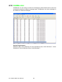
Use Utility to test hardware ..................................................................... 87
CANMonitor ............................................................................................ 88
4.10.1 Function Introduction .................................................................. 89
4.10.2 Introduction to Main Items in Menu Screen ................................ 90
COTI.DLL for CANopen Conformance Test ........................................... 94
5
Pin Assignments and Wiring ........... 95
5.1
Pin Assignments ..................................................................................... 96
Figure 5.1 PCI-1680U/1682U DB-9 pin assignment.................. 96
Wiring...................................................................................................... 96
Table 5.1: PCI-1680U/1682U Pin Wiring and Description......... 96
4.6
4.7
4.8
4.9
4.10
Chapter
5.2
PCI-1680U/1682U User Manual
vi
Chapter
1
1
Introduction
This chapter provides a general
description of the PCI-1680U and
PCI-1682U.
Sections include:
Description
Features
Specifications
Ordering Information
1.1 Description
PCI-1680U/1682U is special purpose communication card that offers connectivity to
Controller Area Networks (CAN) on your PC. With its built-in CAN controllers, the
PCI-1680U/1682U provides bus arbitration and error detection with an automatic
transmission repetition function. This drastically reduces the chance of data loss and
ensures system reliability. You can run both CAN controllers independently at the
same time. The PCI-1680U/1682U operates at baud rates up to 1 Mbps and can be
installed in a PC expansion slot.
Controller Area Network
The CAN (Controller Area Network) is a serial bus system especially suited for networking "intelligent" I/O devices as well as sensors and actuators within a machine or
plant. Characterized by its multi-master protocol, real-time capability, error correction,
high noise immunity, and the existence of many different silicon components, the
CAN serial bus system, originally developed by Bosch for use in automobiles, is
increasingly being used in industrial automation.
Universal PCI
PCI-1680U/1682U provides truly universal connectivity, enabling a single product to
be used to implement systems with dramatically different resource requirements.
This makes PCI-1680U/1682U the most robust, most flexible, and most economical
choice for any application requiring isolation. PCI-1680U/1682U uses a universal PCI
connector compatible with both new 3.3 V signaling support required for plug-in
boards by the PCI 2.2 specification and the 5 V signaling still used by many systems.
Optical Isolation Protection
On-board optical isolators protect your PC and equipment against damage from
ground loops, increasing system reliability in harsh environments.
1.2 Features
PCI bus specification 2.2 compliant
Operates two separate CAN networks at the same time
High speed transmission up to 1 Mbps
16 MHz CAN controller frequency
Optical isolation protection of 1000 VDC ensures system reliability
I/O address automatically assigned by PCI PnP
LED indicates Transmit/Receive status on each port
Windows DLL library and examples included
Supports Windows 2000/XP/Vista/7 (x86 and x64), Linux and QNX
Supports CANopen (PCI-1682U only)
PCI-1680U/1682U User Manual
2
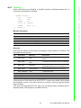
Bus Interface: PCI bus spec. 2.2 compliant
Ports: 2
Protocol: CAN 2.0 A/B
Communication Controller: NXP SJA1000
CAN Transceiver: 82C250
Signal Support: CAN_H, CAN_L
CAN Controller Frequency: 16 MHz
Speed (bps): Up to 1 Mbps programmable transfer rate
Isolation Protection: 1,000 VDC
Connector: Dual DB9 male connectors
Power Consumption: 5 V @ 400 mA (Typical)
Dimensions: 185 x 100 mm
Operating Temperature: 0 ~ 65° C
Storage Temperature: -25 ~ 85° C
Operating Humidity: 5 ~ 95% Relative Humidity, non-condensing
Storage Humidity: 0 ~ 95% Relative Humidity, non-condensing
1.4 Ordering Information
PCI-1680U: 2-port CAN-bus Universal PCI Communication Card with Isolation Protection
PCI-1682U: 2-port CAN-bus Universal PCI Communication Card with CANopen Support
3
PCI-1680U/1682U User Manual
Introduction
Chapter 1
1.3 Specifications
PCI-1680U/1682U User Manual
4
Chapter
2
2
Install WDM driver
This chapter shows how to install
WDM driver.
Sections include:
PCI device setup
ISA device setup
Port setup
Device setup
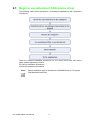
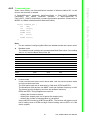
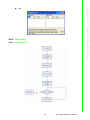
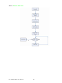
2.1 Begin to use Advantech CAN device driver
The following chart shows procedures of developing applications with Advantech
CAN Driver.
There are different installation procedures for PCI device driver and ISA device
driver, please respectively refer to:
PCI device installation procedures
ISA device installation procedures
Note!
Default installation path for Advantech CAN WDM Driver is C:\Program
Files\Advantech\AdvCAN.
PCI-1680U/1682U User Manual
6
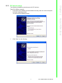
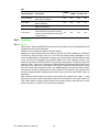
The following installation procedures are for PCI devices.
Take PCI-1680 as example:
1. First make sure hardware can be installed normally, then turn on the computer
and enter operating system.
You will see the following screen.
Chapter 2
2.1.1 PCI device setup
Install WDM driver
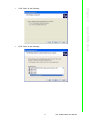
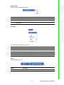
2.
Click "Next" as the following.
7
PCI-1680U/1682U User Manual
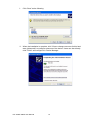
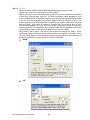
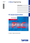
3.
Click "Finish" as the following.
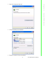
2.1.2 ISA device setup
The following installation procedures are for ISA devices.
Take PCM-3680 as an example.
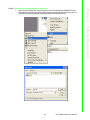
1. Follow the instructions in the manual to install the device, then turn on the computer to enter operating system.
2. Enter Control Panel, then select "Add Hardware".
PCI-1680U/1682U User Manual
8
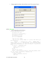
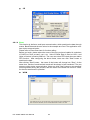
4.
Click "Next" as the following.
Install WDM driver
Click "Next" as the following.
Chapter 2
3.
9
PCI-1680U/1682U User Manual
5.
Click "Next" as the following.
6.
Click "Next" as the following.
PCI-1680U/1682U User Manual
10
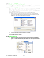
Click "Have Disk...".
8.
Suppose inf file is installed under C:\Program Files\Advantech\AdvCAN\inf, click
"Next" as the following.
Chapter 2
7.
PCI-1680U/1682U User Manual
Install WDM driver
11
9.
Click "Next" as the following.
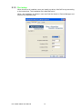
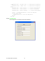
10. When the installation is complete, click "View or change resources for this hard
ware (Advanced)" to configure resources of the device. Users can also directly
click "Finish" and configure it in Device Manager.
PCI-1680U/1682U User Manual
12
Chapter 2
11. Select "Set Configuration Manually".
Install WDM driver
12. Configure according to your hardware.
13. Restart the computer to finish the installation.
13
PCI-1680U/1682U User Manual
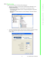
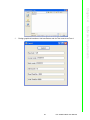
2.1.3 Port setup
When bus driver is installed, users can install port driver AdvCanPort.sys according
to the instructions. The installation file is AdvCanPort.inf.
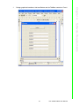
When the installation is finished, users can find the device in Device Manager and
set ports in properties page.
PCI-1680U/1682U User Manual
14
2.
Click the eAutomation CAN port that you want to configure, and select "Properties" to open properties page of the port. Users can set the device in
PORT_INFO.
15
PCI-1680U/1682U User Manual
Install WDM driver
Users can set the device in "Windows Device Manager".
1. When driver is installed, users can open "Windows Device Manager" to set
Advantech CAN device;
" Windows Device Manager" can be opened in the following two ways:
– Control Panel->Administrative Tools->Computer Management, then select
"Device Manager";
– Right click icon of "My Computer" and click "Manage", then select "Device
Manager".
Chapter 2
2.1.4 Device setup
PCI-1680U/1682U User Manual
16
Chapter
3
3
Hardware Installation
This chapter covers inspection
and installation of hardware and
drivers.
Sections include:
Initial inspection
Jumper locations & setting
Card installation
3.1 Initial Inspection
You should find the following items inside the shipping package:
PCI communication interface card
Industrial Communication Driver, Utility and PCI communication card user's
manual in ICOM CD-ROM
PCI-1680U/1682U was carefully inspected mechanically and electrically before it
was shipped. It should be free of marks and scratches and in perfect working order
when received.
As you unpack the PCI-1680U/1682U, check for signs of shipping damage (damaged
box, scratches, dents, etc.). If it is damaged or it fails to meet specifications, notify
our service department or your local sales representative immediately. Also notify the
carrier. Retain the shipping carton and packing material for inspection by the carrier.
After inspection we will make arrangements to repair or replace the unit.
When you handle the PCI-1680U/1682U, remove it from its protective packaging by
grasping the rear metal panel. Keep the anti-vibration packing. Whenever you
remove the card from the PC, store it in this package for protection.
Warning! Discharge your body's static electric charge by touching the back of the
grounded chassis of the system unit (metal) before handling the board.
You should avoid contact with materials that hold a static charge such
as plastic, vinyl and Styrofoam. Handle the board only by its edges to
avoid static damage to its integrated circuits. Avoid touching the
exposed circuit connectors. We also recommend that you use a
grounded wrist strap and place the card on a static dissipative mat
whenever you work with it.
PCI-1680U/1682U User Manual
18
Chapter 3
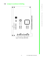
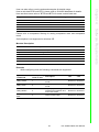
3.2 Jumper Locations & Setting
Hardware Installation
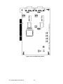
Figure 3.1 PCI-1680U Silk Screen
19
PCI-1680U/1682U User Manual
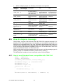
Figure 3.2 PCI-1682U Silk Screen
PCI-1680U/1682U User Manual
20
You configure your card to match the needs of your application by setting jumpers. A
jumper is the simplest kind of electric switch. It consists of two metal pins and a small
metal clip (often protected by a plastic cover) that slides over the pins to connect
them. To "close" a jumper you connect the pins with the clip. To "open" a jumper you
remove the clip.
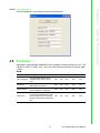
3.2.2 Terminator Resistor Setup
You can set the terminator resistor if necessary to match impedance. Each port has a
separate resistor.
Table 3.1: PCI-1680U/1682U Terminator Resistor Reference
Status
Value of Terminator Resistor
Open mode
0
Close mode
120
3.3 Card Installation
Note!
Make sure you have installed the driver before installing the card. We
strongly recommend that you install the software driver before installing
the hardware into your system, since this will guarantee a smooth and
trouble-free installation process.
Warning! Turn off your PC's power supply whenever you install or remove the PCI
communication card or its cables. Static electricity can easily damage
computer equipment. Ground yourself by touching the chassis of the
computer (metal) before you touch any boards.
1.
2.
3.
4.
5.
6.
Turn off the computer.
Turn the power off to any peripheral devices (such as printers and monitors).
Disconnect the power cord and any other cables from the back of the computer.
Turn the PC if necessary to gain access to the cables.
Remove the PC's cover (refer to your user's guide if necessary).
Locate the expansion slots or passive back-plane (at the rear of the PC) and
choose any unused slot.
7. Remove the screw that secures the expansion slot cover to the PC (save the
screw to secure the interface card retaining bracket).
8. Remove the anti-vibration card clamp if supplied.
9. Carefully grasp the upper edge of the PCI communication card.
10. Align the hole in the retaining bracket with the hole on top of the expansion slot.
11. Align the gold striped edge connector with the expansion slot socket.
21
PCI-1680U/1682U User Manual
Hardware Installation
Figure 3.3 How to Set Jumpers
Chapter 3
3.2.1 How to Set Jumpers
12.
13.
14.
15.
16.
17.
Press the board firmly into the socket.
Replace the screw in the expansion slot's retaining bracket.
Replace anti-vibration cardholder.
Replace the PC's cover. Connect the cables you removed in step 3.
Turn the computer power on.
The board is now installed in the computer. See Chapter 5 for information on
cabling.
PCI-1680U/1682U User Manual
22
Chapter
4
4
Software
Requirements
This chapter has information on
the software of PCI-1680U/1682U.
4.1 Introduction
PCI-1680U/1682U and PCL-841 are Isolated Dual-port CAN communication cards.
Each provides two isolated CAN ports for communication applications in difficult environments. The chip on the CAN cards is SJA1000. The SJA1000 is a single chip
solution for PC-based CAN port and parallel expansion add-in cards.
This chapter outlines the CAN card's windows DLL driver software requirement specifications. Including functionality, performance, and user interface requirements. It
applies to programming the CAN cards Windows unified DLL driver, including the
driver for PCL841 and PCI1680.
4.1.1 Definitions, Acronyms, and Abbreviations
SRS = Software Requirements Specification
PPI = Programmable Peripheral Interface
GUI = Graphics User Interface
4.1.2 Reference
Please see "SJA1000.pdf" on your CD-ROM for further information on the SJA1000
chip.
4.2 Overview of Advantech CAN Windows
WDM&CE Driver
Advantech CAN Windows WDM&CE Driver is composed of bus drivers, ports drivers,
tools and examples.Bus drivers and ports drivers, which run in PeliCAN mode, are
used to drive SJA1000 chip on Advantech CAN device.Bus drivers and ports drivers
are compliant with PCI and ISA bus, and provide the users with coherent operation
interfaces. Users can directly write applications with windows API.Examples of VC,
VB, VB.NET, C#.NET, VC.NET, eVC are supplied in the package, providing a reference for users to develop applications. When developing work is completed, users
can use test tools to verify if functions of the application are correct.
Features
Supports CAN 2.0B Protocol and compatible with CAN 2.0A Protocol, which
means both Standard frame and Extended frame can be dealt with.
Supports single filter mode and dual filter mode.
Supports Listen-Only Mode.
Supports self reception mode on WDM platform.
Provides API interface similar to windows standard serial port, easy to develop.
Provides tools like CANTest, CANDemo to test the basic functions.
Provides CANMonitor to monitor CAN/CANopen network. A maximum of
1000000 frame data can be reserved a time and meanwhile CAN/CNAopen
messages can be dealt with.
Provides interface COTI.DLL of CANopen Conformance Test Tool. The COTI
DLL allows users to use the CANopen Conformance Test Tool of CiA(CAN in
Automation) with Advantech CAN WDM Driver.
PCI-1680U/1682U User Manual
24
System Requirements
Windows 2000, 32-bit Windows XP, 32-bit Windows Vista, 32-bit Windows 7, 64-bit
Windows XP, 64-bit Windows Vista, 64-bit Windows 7, Windows CE.
The usage of WDM is different from that of CE in the following aspects:
Driver Installation
– WDM: The user should refer to Install WDM Driver to install the driver.
– CE: The driver has been pre-built in Platform image, so the user doesn't need
to install the driver.
Development Kit Installtion
– WDM: none
– CE: Advantech platform SDK
Function
– WDM: Support all the functions listed in the manual.
– CE: Not support self reception function.
Interface
The interfaces that WDM and CE support are almost the same.
The user should pay attention to the following differences:
1. The device name is different.
Here CAN1 is used as an example:
WDM: \\\\.\\CAN1
CE: CAN1:
Functions involved: CreateFile
2. Since OVERLAPPED type is not supported by CE, NULL pointers will be loaded
instead of parameters using OVERLAPPED structure.
Functions involved:DeviceIoControl, ReadFile, WriteFile, WaitCommEvent.
3. OVERLAPPED type is not supported by CE, so does not support GetOverLappedResult function.
25
PCI-1680U/1682U User Manual
Software Requirements
SJA1000
SJA1000 supports BasicCAN mode and PeliCAN mode. BasicCAN mode supports
CAN 2.0A, while PeliCAN mode supports 2.0B. Advantech CAN Windows WDM&CE
Driver runs in PeliCAN mode, thus it can support both Standard frame and Extended
frame.
Chapter 4
CAN 2.0A and CAN 2.0B
CAN2.0 Spec. includes CAN 2.0A and CAN 2.0B. CAN 2.0A supports standard 11 bit
Identifier. CAN 2.0B supports both 11 bit Identifier and extended 29 bit Identifier. So
CAN 2.0B are compatible with CAN 2.0A.
Hardware Support
Table 4.1: Hardware Support
HardWare
Description
WDM
PCM-3680
2 port Isolated ISA CAN bus Card.
Yes
Yes
PCL-841
2 port Isolated ISA CAN bus Card.
Yes
Yes
TPC-662G
1 port Isolated ISA CAN bus Device on
TPC-662G.
Yes
Yes
PCI-1680
2 port Isolated PCI CAN bus Card. Yes
Yes
UNO-2052(E)
2 port Isolated PCI CAN bus Device on
UNO-2052(E).
Yes
Yes
EAMB-PH07
1 port Isolated PCI CAN bus Card.
Yes
Yes
TPC-68T
1 port Isolated ISA CAN bus Device on
TPC-68T.
No
Yes
TPC-120H
1 port Isolated ISA CAN bus Device on
TPC-120H.
No
Yes
TPC-32T
1 port Isolated ISA CAN bus Device on
TPC-32T.
No
Yes
AMAX-2050
1 port Isolated PCI CAN bus Device on
AMAX-2050.
No
Yes
ADAM-5095
2 port Isolated PCI CAN bus Card.
No
Yes
ADVANTECH GENERAL CAN
PORT (1 PORT)
1 port Isolated PCI CAN bus Card.
Yes
Yes
ADVANTECH GENERAL CAN
PORT (2 PORT)
2 port Isolated PCI CAN bus Card.
Yes
Yes
ADVANTECH GENERAL CAN
PORT (4 PORT)
4 port Isolated PCI CAN bus Card.
Yes
Yes
ADVANTECH GENERAL CAN
PORT (1 PORT, support CANopen)
1 port Isolated PCI CAN bus Card and
support CANopen.
Yes
Yes
ADVANTECH GENERAL CAN
PORT (2 PORT, support CANopen)
2 port Isolated PCI CAN bus Card and
support CANopen.
Yes
Yes
ADVANTECH GENERAL CAN
PORT (4 PORT, support CANopen)
4 port Isolated PCI CAN bus Card and
support CANopen.
Yes
Yes
Users of Windows CE can refer to Guide for developing applications
References
"SJA1000 Standard-alone CAN controller"
PCI-1680U/1682U User Manual
26
CE
Main API used in current development are:
CreateFile
Open specified Can port.
CloseHandle
Close specified Can port.
DeviceIoControl
Send commands to drivers, including configuration, management
and getting status, etc.
Read data.
WriteFile
Send data.
GetOverLappedResult
Wait until asynchronous operation is finished.
SetCommMask
Set mask.
GetCommMask
Get mask.
WaitCommEvent
Wait specified event.
ClearCommError
Get error code with this function when receiving error event.
Only brief introduction is given in this manual regarding detailed usage of each function.Notes are made to notify users of important operation.For more detailed information about the usage, please see MSDN.
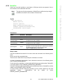
4.3.1 CreateFile
Users can use this interface to open CAN port device.
Close the port by calling CloseHandle when operation is completed.
Note!
This driver does not support share open function, so the third parameter
must be set to 0.
Syntax
HANDLE CreateFile(
LPCTSTR lpFileName,
DWORD dwDesiredAccess,
DWORD dwShareMode,
LPSECURITY_ATTRIBUTES lpSecurityAttributes,
DWORD dwCreationDisposition,
DWORD dwFlagsAndAttributes,
HANDLE hTemplateFile
);
27
PCI-1680U/1682U User Manual
Software Requirements
ReadFile
Chapter 4
4.3 Introduction to API
Parameters
Name
Direction Description
lpFileName
Input
Name of device which was opened, such as
\\\\.\\CAN1. *Note
In WINDOWS CE,use CAN1:.
ldwDesiredAccess
Input
Ways of opening the port, which is usually
GENERIC_READ | GENERIC_WRITE.
dwShareMode
Input
Does not support share open. It must be set to 0.
lpSecurityAttributes
Input
NULL.
dwCreationDisposition
Input
OPEN_EXISTING.
dwFlagsAndAttributes
Input
Synchronous open: FILE_ATTRIBUTE_NORMAL.
Asynchronous open:
FILE_ATTRIBUTE_NORMAL|FILE_FLAG_OVERLAP
PED.
hTemplateFile
Input
NULL.
Return Value
Successful, return effective HANDLE. Unsuccessful, return
INVALID_HANLDLE_VALUE.
Example
Synchronous open CAN1:
HANDLE hDevice = CreateFile(
"\\\\.\\CAN1",
GENERIC_READ | GENERIC_WRITE,
0,
NULL,
OPEN_EXISTING,
FILE_ATTRIBUTE_NORMAL,
NULL);
Asynchronous open CAN1£½
HANDLE hDevice = CreateFile(
"\\\\.\\CAN1",
GENERIC_READ | GENERIC_WRITE,
0,
NULL,
OPEN_EXISTING,
FILE_ATTRIBUTE_NORMAL|FILE_FLAG_OVERLAPPED,
NULL);
PCI-1680U/1682U User Manual
28
Close the port by calling this function when operation is completed.
Syntax
BOOL CloseHandle(
HANDLE hDevice
);
Name
Direction
Description
hDevice
Input
Handle of the device which was opened.
Return Value
Successful: return non-zero values. Unsuccessful: return zero value. Please call GetLastError function.
Example
//close
BOOL bRet = CloseHandle(hDevice);
See Also
CreateFile
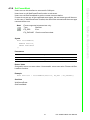
4.3.3 DeviceIoControl
Users can use this interface to send commands, configure ports, like stop device,
start device, configure Baud Rate, etc.
See Command_par, CanStatusPar_t for detailed configuration.
Syntax
BOOL DeviceIoControl(
HANDLE hDevice,
DWORD dwIoControlCode,
LPVOID lpInBuffer,
DWORD nInBufferSize,
LPVOID lpOutBuffer,
DWORD nOutBufferSize,
LPDWORD lpBytesReturned,
LPOVERLAPPED lpOverlapped
);
29
PCI-1680U/1682U User Manual
Software Requirements
Parameters
Chapter 4
4.3.2 CloseHandle
Parameters
Name
Direction Description
hDevice
Input
Handle of the device which was opened.
dwIoControlCode
Input
Control code, shows the specific operation mode.
lpInBuffer
Input
Start address sent to data area of driver.
nInBufferSize
Input
Byte length sent to data area of driver.
lpOutBuffer
Output
Address of data area which receives driver's return data.
nOutBufferSize
Input
Byte length of data area which receives driver's return data.
lpBytesReturned
Output
Real byte length of data received from driver.
Input
If CreateFile uses asynchronous open, asynchronous operation must be supported here. Please refer to MSDN for
detailed instruction to asynchronous open.
*Note In WINDOWS CE,set to NULL.
lpOverlapped
Return Value
Successful: return non-zero values. Unsuccessful: return zero value. Please call GetLastError function.
It will be considered unsuccessful if zero values are returned in the following situation. Please call GetLastError.
In work mode, drivers can not complete some of the requests, GetLastError will be
called to return ERROR_GEN_FAILURE.
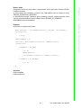
Example
Set baud rate:
DWORD dwReturned;
Command_par_t cmd;
Config_par_t config;
cmd.cmd = CMD_STOP;
BOOL bSuccess = DeviceIoControl (
hDevice,
CAN_IOCTL_COMMAND,
&cmd,
sizeof(Command_par),
NULL,
0,
&dwReturned,
NULL
);
if(!bSuccess)
{
//error
}
config.target = CONF_TIMING;
config.val1 = 1000; //set 1000K
PCI-1680U/1682U User Manual
30
Chapter 4
Software Requirements
bSuccess = DeviceIoControl (
hDevice,
CAN_IOCTL_CONFIG,
&config,
sizeof(Command_par),
NULL,
0,
&dwReturned,
NULL
);
if(!bSuccess)
{
//error
}
cmd.cmd = CMD_START;
bSuccess = DeviceIoControl (
hDevice,
CAN_IOCTL_COMMAND,
&cmd,
sizeof(Command_par),
NULL,
0,
&dwReturned,
NULL
);
if(!bSuccess)
{
//error
}
Set acceptance filter:
DWORD dwReturned;
Command_par_t cmd;
Config_par_t config;
cmd.cmd = CMD_STOP;
BOOL bSuccess = DeviceIoControl (
hDevice,
CAN_IOCTL_COMMAND,
&cmd,
sizeof(Command_par),
NULL,
0,
&dwReturned,
NULL
);
if(!bSuccess)
{
31
PCI-1680U/1682U User Manual
//error
}
config.target = CONF_ACC_FILTER;
config.val1 = 1; //1: set single filter mode; 0: set dual
filter mode
bSuccess = DeviceIoControl (
hDevice,
CAN_IOCTL_CONFIG,
&config,
sizeof(Command_par),
NULL,
0,
&dwReturned,
NULL
);
if(!bSuccess)
{
//error
}
config.target = CONF_ACC;
config.val1 = 0xffffffff;
config.val2 = 0xffffffff;
bSuccess = DeviceIoControl (
hDevice,
CAN_IOCTL_CONFIG,
&config,
sizeof(Command_par),
NULL,
0,
&dwReturned,
NULL
);
if(!bSuccess)
{
//error
}
cmd.cmd = CMD_START;
bSuccess = DeviceIoControl (
hDevice,
CAN_IOCTL_COMMAND,
&cmd,
sizeof(Command_par),
NULL,
0,
&dwReturned,
NULL
PCI-1680U/1682U User Manual
32
Chapter 4
Software Requirements
);
if(!bSuccess)
{
//error
}
Set listen only mode:
DWORD dwReturned;
Command_par_t cmd;
Config_par_t config;
cmd.cmd = CMD_STOP;
BOOL bSuccess = DeviceIoControl (
hDevice,
CAN_IOCTL_COMMAND,
&cmd,
sizeof(Command_par),
NULL,
0,
&dwReturned,
NULL
);
if(!bSuccess)
{
//error
}
config.target = CONF_LISTEN_ONLY_MODE;
config.val1 = 1; //1: ON; 0: OFF
bSuccess = DeviceIoControl (
hDevice,
CAN_IOCTL_CONFIG,
&config,
sizeof(Command_par),
NULL,
0,
&dwReturned,
NULL
);
if(!bSuccess)
{
//error
}
cmd.cmd = CMD_START;
bSuccess = DeviceIoControl (
hDevice,
CAN_IOCTL_COMMAND,
&cmd,
33
PCI-1680U/1682U User Manual
sizeof(Command_par),
NULL,
0,
&dwReturned,
NULL
);
if(!bSuccess)
{
//error
}
Reset chip:
DWORD dwReturned;
Command_par_t cmd;
cmd.cmd = CMD_RESET;
BOOL bSuccess = DeviceIoControl (
hDevice,
CAN_IOCTL_COMMAND,
&cmd,
sizeof(Command_par),
NULL,
0,
&dwReturned,
NULL
);
if(!bSuccess)
{
//error
}
cmd.cmd = CMD_START;
bSuccess = DeviceIoControl (
hDevice,
CAN_IOCTL_COMMAND,
&cmd,
sizeof(Command_par),
NULL,
0,
&dwReturned,
NULL
);
if(!bSuccess)
{
//error
}
PCI-1680U/1682U User Manual
34
Clear receive buffer:
DWORD dwReturned;
Command_par_t cmd;
cmd.cmd = CMD_CLEARBUFFERS;
Chapter 4
Software Requirements
BOOL bSuccess = DeviceIoControl (
hDevice,
CAN_IOCTL_COMMAND,
&cmd,
sizeof(Command_par),
NULL,
0,
&dwReturned,
NULL
);
if(!bSuccess)
{
//error
}
Get status of device:
DWORD dwReturned;
CanStatusPar_t status;
BOOL bSuccess = DeviceIoControl (
hDevice,
CAN_IOCTL_STATUS,
NULL,
0,
&status,
sizeof(CanStatusPar_t),
&dwReturned,
NULL
);
See Also
Command_par
CanStatusPar_t
35
PCI-1680U/1682U User Manual
4.3.4 ReadFile
Users can use this interface to read data from CAN port which was opened. One or
more frames can be selected each time.
Note!
The third and fourth parameters of ReadFile are defined as byte length
in MSDN, but stand for the number of frames in Advantech CAN Windows WDM&CE Driver.
Syntax
BOOL ReadFile(
HANDLE hDevice,
LPVOID lpBuffer,
DWORD nNumberOfFramesToRead,
LPDWORD lpNumberOfFramesRead,
LPOVERLAPPED lpOverlapped
);
Parameters
Name
Direction
Description
hDevice
Input
Handle of the device which was opened.
lpBuffer
Output
Start address of receive buffer.
nNmberOfFramesToRead
Input
Number of frames to be received from drivers. The definition here is different from that in MSDN.
lpNumberOfFramesRead
Output
Real number of frames received from driver. The definition
here is different from that in MSDN.
Input
If CreateFile uses asynchronous open, asynchronous operation must be supported here. Please refer to MSDN for
detailed instruction to asynchronous open.
*Note In WINDOWS CE,set to NULL.
lpOverlapped
PCI-1680U/1682U User Manual
36
Example
Read one frame data in synchronous mode.
DWORD dwRead;
canmsg_t ReadBuffer;
ZeroMemory(&ReadBuffer, sizeof(canmsg_t));
BOOL bSuccess = ReadFile(hDevice, &ReadBuffer, 1, &dwRead,
0);
if(bSuccess)
{
if(dwRead == 1)
{
//SUCCESS
if(ReadBuffer.flags & MSG_EXT)
{
//Extended frame
}
else{
//Standard frame
}
if(ReadBuffer.flags & MSG_RTR)
{
//Remote frame
}
if(ReadBuffer.flags & MSG_SELF)
{
//self reception
}
if(ReadBuffer.flags & MSG_BOVR)
37
PCI-1680U/1682U User Manual
Software Requirements
It will be considered unsuccessful if zero values are returned in the following situations. Please call GetLastError.
If users cancel the operation or reset chip while drivers are receiving data, GetLastError will be called to return ERROR_OPERATION_ABORTED.
If busoff of device is discovered before drivers read any frames, GetLastError will be
called to return ERROR_GEN_FAILURE.
If drivers cannot allocate resources according to the number defined by the third
parameter
frame,
GetLastError
will
be
called
to
return
ERROR_INVALID_PARAMETER.
In asynchronous mode, operation will be pending if drivers cannot complete user's
read request, and GetLastError will be called to return ERROR_IO_PENDING.
See MSDN for more information.
Chapter 4
Return Value
It will be considered successful if non-zero values are returned in the following situations:
1. The driver reads data and there is no data in the receive buffer. At this time, the
data received is less than the requested data.
2. The driver reads all the requested data.
3. The driver can not read any data and time is out.
{
//receive buffer overflow
}
if(ReadBuffer.flags &
{
//CAN controller
}
if(ReadBuffer.flags &
{
//CAN controller
}
if(ReadBuffer.flags &
{
//CAN controller
}
MSG_BUSOFF)
bus off
MSG_OVR)
Msg overflow error
MSG_PASSIVE)
in error passive
}
else{
//Timeout
}
}
else{
DWORD dwError = GetLastError();
if (dwError == ERROR_IO_PENDING)
{
//pengding
}
else if(dwError == ERROR_INVALID_PARAMETER)
{
//parameter error
}
else if(dwError == ERROR_OPERATION_ABORTED)
{
//cancelled
}
else if(dwError == ERROR_GEN_FAILURE)
{
//bus off
}
}
PCI-1680U/1682U User Manual
38
Users can use this interface to send data to CAN port which was opened. One or
more frames can be selected each time.
Note!
The third and fourth parameters of WriteFile are defined as byte length
in MSDN, but stand for the number of frames here.
Parameters
Name
Direction
Description
hDevice
Input
Handle of the device which was opened.
lpBuffer
Input
Start address of send buffer.
nNmberOfFramesToWrite
Input
Number of frames to be sent to drivers. The definition here
is different from that in MSDN.
lpNumberOfFramesWritten
Output
Real number of frames sent to driver. The definition here
is different from that in MSDN.
Input
If CreateFile uses asynchronous open, asynchronous
operation must be supported here. Please refer to MSDN
for detailed instruction to asynchronous open.
*Note In WINDOWS CE,set to NULL.
lpOverlapped
Return Value
It will be considered successful if non-zero values are returned in the following situations:
Driver send all the requested data.
Timeout occur when driver only send part of the data or no data.
It will be considered unsuccessful if zero values are returned in the following situations. Please call GetLastError.
If user cancel the operation or reset chip while drivers are sending data, GetLastError will be called to return ERROR_OPERATION_ABORTED.
If busoff of device is discovered before drivers send any frames, GetLastError will be
called to return ERROR_GEN_FAILURE.
If drivers cannot allocate resources according to the number defined by the third
parameter
frame,
GetLastError
will
be
called
to
return
ERROR_INVALID_PARAMETER.
39
PCI-1680U/1682U User Manual
Software Requirements
Syntax
BOOL WriteFile(
HANDLE hDevice,
LPCVOID lpBuffer,
DWORD nNumberOfFramesToWrite,
LPDWORD lpNumberOfFramesWritten,
LPOVERLAPPED lpOverlapped
);
Chapter 4
4.3.5 WriteFile
In asynchronous mode, operation will be pending if drivers cannot complete user's
write request at present, and GetLastError will be called to return
ERROR_IO_PENDING.
See MSDN for more information.
Example
Write one frame data in synchronous mode.
DWORD dwWrite;
canmsg_t WriteBuffer;
ZeroMemory(&WriteBuffer, sizeof(canmsg_t));
//WriteBuffer.flags = 0; //Standard frame
WriteBuffer.flags = MSG_EXT; //Extended frame
//WriteBuffer.flags |= MSG_RTR; //Remote frame
WriteBuffer.id = 0;
WriteBuffer.length = DATALENGTH;
for(int i=0; i<DATALENGTH; i++)
{
WriteBuffer.data[i] = i;
}
BOOL bSuccess = WriteFile(hDevice, &WriteBuffer, 1, &dwWrite,
0);
if(bSuccess)
{
if(dwWrite == 1)
{
//SUCCESS
}
else{
//Timeout
}
}
else{
DWORD dwError = GetLastError();
if (dwError == ERROR_IO_PENDING)
{
//pengding
}
else if(dwError == ERROR_INVALID_PARAMETER)
{
//parameter error
}
else if(dwError == ERROR_OPERATION_ABORTED)
{
//cancelled
}
else if(dwError == ERROR_GEN_FAILURE)
{
//bus off
}
}
PCI-1680U/1682U User Manual
40
Users can use this interface to set event for CAN port.
Users have to call WaitCommEvent function to wait event.
Users can call GetCommMask to get the current event set before.
If users do not set any of the supported event types, the real event type will be zero.
In this case, if WaitCommEvent is called, the call will be returned and the event type
returned will be zero.
Events supported at present are only:
Type
Direction
EV_ERR
Error
EV_RXCHAR Receive one frame data
Syntax
BOOL SetCommMask(
HANDLE hDevice,
DWORD dwEvtMask
);
Parameters
Name
Direction
Description
hDevice
Input
Handle of the device which was opened.
dwEvtMask
Input
Event type.
Return Value
Successful: return non-zero values. Unsuccessful: return zero value. Please call GetLastError function.
Example
BOOL bSuccess = SetCommMask(hDevice, EV_ERR | EV_RXCHAR);
See Also
WaitCommEvent
GetCommMask
41
PCI-1680U/1682U User Manual
Software Requirements
Note!
Chapter 4
4.3.6 SetCommMask
4.3.7 GetCommMask
Users can call GetCommMask to get event type set in SetCommMask.
Syntax
BOOL GetCommMask(
HANDLE hDevice,
LPDWORD lpEvtMask
);
Parameters
Name
Direction
Description
hDevice
Input
Handle of the device which was opened.
lpEvtMask
Output
Store event type which return from drivers.
Return Value
Successful: return non-zero values. Unsuccessful: return zero value. Please call GetLastError function.
Example
DWORD dwMask = 0;
BOOL bSuccess = GetCommMask(hDevice, &dwMask);
See Also
SetCommMask
4.3.8 WaitCommEvent
After calling SetCommMask to set event, users should also call WaitCommEvent
function to wait event.
Syntax
BOOL WaitCommEvent(
HANDLE hDevice,
LPDWORD lpEvtMask,
LPOVERLAPPED lpOverlapped
);
Parameters
Name
Direction
Description
hDevice
Input
Handle of the device which was opened.
lpEvtMask
Output
Event type.
Output
If CreateFile uses asynchronous open, asynchronous operation must be supported here. Please refer to MSDN for
detailed instruction to asynchronous open.
*Note In WINDOWS CE,set to NULL.
lpOvelapped
PCI-1680U/1682U User Manual
42
BOOL bSuccess = SetCommMask(hDevice, EV_ERR | EV_RXCHAR);
if(!bSuccess)
{
//error
}
DWORD dwMask = 0;
bSuccess = WaitCommEvent(hDevice, &dwMask, NULL);
if(bSuccess)
{
if(dwMask & EV_ERR)
{
//to do
DWORD dwError;
ClearCommError(hDevice, &dwError, NULL);
}
if(dwMask & EV_RXCHAR)
{
//to do
}
}
See Also
SetCommMask
ClearCommError
43
PCI-1680U/1682U User Manual
Software Requirements
Example
Wait event in synchronous mode.
Chapter 4
Return Value
Successful: return non-zero values. Unsuccessful: return zero value. Please call GetLastError function.
If users cancel the operation or reset chip, GetLastError will be called to return
ERROR_OPERATION_ABORTED.
In asynchronous mode, operation will be pending if drivers cannot complete user's
request, and GetLastError will be called to return ERROR_IO_PENDING.
See MSDN for more information.
4.3.9 ClearCommError
When error occurs, users can use ClearCommError to get the specific type of error.
Note!
Definitions of error codes supported are as below:
Name
Description
CE_RXOVER
Receive Queue overflow.
CE_OVERRUN Receive Overrun Error.
CE_FRAME
Passive error.
CE_BREAK
Busoff .
Note!
The third parameter is unused, please set it to NULL.
Syntax
BOOL ClearCommError(
HANDLE hDevice,
LPDWORD lpErrors,
LPCOMSTAT lpStat
);
Parameters
Name
Direction
Description
hDevice
Input
Handle of the device which was opened.
lpErrors
Output
Store error codes which return from drivers.
lpStat
Output
Empty. If users want to know specific information about error
register, please call DeviceIoControl to get status of the
device.
Return Value
Successful: return non-zero values. Unsuccessful: return zero value. Please call GetLastError function.
PCI-1680U/1682U User Manual
44
See Also
WaitCommEvent
DeviceIoControl
45
PCI-1680U/1682U User Manual
Software Requirements
DWORD dwMask;
BOOL bSuccess = WaitCommEvent(hDevice, &dwMask, NULL);
if(bSuccess)
{
if(dwMask & EV_ERR)
{
//to do
DWORD dwError;
bSuccess = ClearCommError(hDevice, &dwError, NULL);
if(bSuccess)
{
//to do
if(dwError& CE_FRAME || dwError& CE_BREAK)
{
CanStatusPar_t status;
DWORD dwReturned;
DeviceIoControl (hDevice,
CAN_IOCTL_STATUS,
NULL,
0,
&status,
sizeof(CanStatusPar_t),
&dwReturned,
NULL
);
}
}
}
Chapter 4
Example
Wait event in synchronous mode.
4.3.10 GetOverlappedResult
When user's operation cannot be finished immediately in asynchronous mode, this
function should be called to wait operation to be completed.
Syntax
BOOL GetOverlappedResult(
HANDLE hDevice,
LPOVERLAPPED lpOverlapped,
LPDWORD lpNumberOfFramesTransferred,
BOOL bWait
);
Parameters
Name
Direction Description
hDevice
Input
Handle of the device which was opened.
lpOverlapped
Input
Events need to be waited are included. Refer to MSDN
for more information.
lpNumberOfFramesTransferred
Output
ReadFile and WriteFile are real numbers of data written
and read; WaitCommEvent is not defined.
Input
TRUE, will not return until read/write operation is finished. FALSE, return immediately no matter the operation is finished or not. Call GetLastError to return
ERROR_IO_INCOMPLETE. Refer to MSDN for
detailed information.
bWait
Return Value
Successful: return non-zero values. Unsuccessful: return zero value. Please call GetLastError function.
Example
#include <windows.h>
#include <stdio.h>
void main( )
{
HANDLE hDevice;
OVERLAPPED ov;
BOOL bSuccess;
DWORD dwEvtMask;
DWORD dwLength;
hDevice = CreateFile( "\\\\.\\CAN1",
GENERIC_READ | GENERIC_WRITE,
0, // exclusive access
NULL, // default security attributes
OPEN_EXISTING,
FILE_FLAG_OVERLAPPED,
NULL
);
PCI-1680U/1682U User Manual
46
bSuccess = SetCommMask(hDevice, EV_ERR | EV_RXCHAR);
if (!bSuccess)
{
// Handle the error.
printf("SetCommMask failed with error %d.\n", GetLastError());
return;
}
// Create an event object for use by WaitCommEvent.
ov.hEvent = CreateEvent(
NULL, // default security attributes
FALSE, // auto reset event
FALSE, // not signaled
NULL // no name
);
// Intialize the rest of the OVERLAPPED structure to
zero.
ov.Internal = 0;
ov.InternalHigh = 0;
ov.Offset = 0;
ov.OffsetHigh = 0;
if (WaitCommEvent(hDevice, &dwEvtMask, &ov))
{
if (dwEvtMask & EV_ERR)
{
// To do.
}
if (dwEvtMask & EV_RXCHAR)
{
// To do.
47
PCI-1680U/1682U User Manual
Software Requirements
// Set the event mask.
Chapter 4
if (hDevice == INVALID_HANDLE_VALUE)
{
// Handle the error.
printf("CreateFile failed with error %d.\n", GetLastError());
return;
}
}
}
else
{
DWORD dwRet = GetLastError();
if( ERROR_IO_PENDING == dwRet)
{
printf("I/O is pending...\n");
if(GetOverlappedResult(hDevice, &ov, &dwLength,
TRUE))
{
//To do
}
else
{
//To do
}
}
else
printf("Wait failed with error %d.\n", GetLastError());
}
}
See Also
ReadFile WriteFile
WaitCommEvent
4.4 Structure List
The table below is a list of structures needed by Advantech CAN WDM Driver.
Methods:
canmsg_t
Received/Sent message structure.
CanStatusPar_t
Port status structure.
Command_par
Command/Configure operation structure.
PCI-1680U/1682U User Manual
48
When users directly use ReadFile or WriteFile interface of Windows Native API to
call drivers, this structure is needed.
Member Description
Name
Description
flags
Types of messages.
cob
Reserved.
id
ID of message.
length
of messages (0~8).
data
Data transferred (Made up of 0°´8 Byte data).
Remarks
8-bit flags are used to record types of messages during sending or receiving. The
meanings of these bits are:
Bit
Declaration
Meaning
Description
0
MSG_RTR
RTR
1 means Remote frame, 0 means data
frame.
1
MSG_OVR
Hardware OVERRUN
1 means receive buffer overrun of hardware.
2
MSG_EXT
Extension
1 means Extended frame(29 bit identifier), 0
means Standard frame(11 bit identifier).
3
MSG_SELF
Self Reception
1 means self sending and receiving frame, 0
means receiving frame from other ports.
4
MSG_PASSIVE
Error
1 means bus error.
1 means busoff.
5
MSG_BUSOFF
BUSOFF
6
Reserved
Reserved
7
MSG_BOVR
Software OVERRUN 1 means receive buffer overrun of software.
ID shows type of CAN. When ID is 0xFFFFFFFF, it means error frame, which implies
that hardware overrun, error and busoff occur in drivers. Users can get the specific
type from flags.
If ID does not equal 0xFFFFFFFF, flags may be Remote frame, Extended frame,
Standard frame, Self Reception or software overrun.
49
PCI-1680U/1682U User Manual
Software Requirements
typedef struct {
int
flags;
int
cob;
ULONG
id;
short int length;
UCHAR
data[ 8 ];
} canmsg_t;
Chapter 4
4.4.1 canmsg_t
4.4.2 CanStatusPar_t
DeviceIOControl's
parameter
dwIoControlCode
(0x222554). It uses this structure.
is
CAN_IOCTL_STATUS
typedef struct {
unsigned int baud;
unsigned int status;
unsigned int error_warning_limit;
unsigned int rx_errors;
unsigned int tx_errors;
unsigned int error_code;
unsigned int rx_buffer_size;
unsigned int rx_buffer_used;
unsigned int tx_buffer_size;
unsigned int tx_buffer_used;
ULONG
retval;
unsigned int type;
unsigned int acceptancecode;
unsigned int acceptancemask;
unsigned int acceptancemode;
unsigned int selfreception;
unsigned int readtimeout;
unsigned int writetimeout;
} CanStatusPar_t, *PCcanStatusPar_t;
Member Description
Name
Description
baud
Actual bit rate.
status T
he status register (SR); CAN address 2.
error_warning_limit
The error warning limit register (EWLR); CAN address 13.
rx_errors
The RX error counter register (RXERR); CAN address 14.
tx_errors
The TX error counter register (TXERR); CAN address 15.
error_code
The error code capture register (ECC); CAN address 12.
rx_buffer_size
Size of rx buffer.
rx_buffer_used
Number of received messages.
tx_buffer_size
Size of tx buffer for wince.
tx_buffer_used
Number of messages of tx buffer for wince.
retval
Return Value. 0, SUCCESS; 0xFFFFFFFF, FAIL.
type
CAN controller type. 1, SJA1000; 0 other device.
acceptancecode
Acceptance code.
acceptancemask
Acceptance mask.
acceptancemode
Acceptance Filter Mode: 1:Single 0:Dual.
selfreception
Self reception.
ReadTimeout
Read timeout.
WriteTimeout
Write timeout.
PCI-1680U/1682U User Manual
50
When users directly use DeviceIOControl interface of Windows Native API to call
drivers, this structure is needed.
If DeviceIOControl's parameter dwIoControlCode is CAN_IOCTL_COMMAND
(0x222540), this means command operation. If dwIoControlCode is
CAN_IOCTL_CONFIG (0x222544), it means configuration operation. (Please refer to
MSDN for related information about DeviceIOControl).
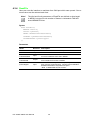
Note
1. The two modes of configuring Baud Rate are standard mode and custom mode.
Standard mode
The standard mode includes the recommended Baud Rate value. If the setting
value is 10, then the Baud Rate will be 10k.
Target value
BTR0
BTR1
Setting value
10K
0x31
0x1c
10
20K
0x18
0x1c
20
50K
0x09
0x1c
50
100K
0x04
0x1c
100
125K
0x03
0x1c
125
250K
0x01
0x1c
250
500K
0x00
0x1c
500
800K
0x00
0x16
800
1000K
0x00
0x14
1000
Custom mode
If user need the baud rate is not in above table, user can use the custom mode
to set the custom baud rate.
The CAN port's baud rate is determine by CAN clock, BTR0 and BTR1 .
The Advantech CAN devices use 8MHZ clock and oscillator frequency is 16M,
The internal clock is divided by two from the oscillator frequency.
BTR0 and BTR1 Timing Registers are used for:
– defining the bit-rate on the bus.
– defining the sample point in a bit period (bit sample point).
– defining the number of samples taken in a bit period.
we provide API function to set BTR0 and BTR1, The function will write the low 8
bits of setting value to BTR0 and high 8 bits of setting value to BTR1 of CAN
device register.
51
PCI-1680U/1682U User Manual
Software Requirements
struct Command_par {
int
cmd;
int
target;
ULONG val1;
ULONG val2;
int
error;
ULONG retval;
};
Chapter 4
4.4.3 Command_par
The following code is the example to custom baud rate by setting BTR0 and
BTR1 device register.
AdvCANIO.h Line:269
/
**************************************************************
***************
*
* acSetBaudRegister
*
* Purpose:
* Configures baud rate by custom mode.
*
*
* Arguments:
* hDevice - handle of device
* Btr0 - BTR0 register value.
* Btr1 - BTR1 register value.
* Returns:
* =0 SUCCESS; or <0 failure
*
************************************************************
*****************/
int acSetBaudRegister(HANDLE hDevice, unsigned char Btr0,
unsigned char Btr1)
{
unsigned int BaudRateValue = Btr0 * 256;
BaudRateValue += Btr1;
return acSetBaud(hDevice, BaudRateValue);
}
can_receive.cpp Line:105
nRet = acSetBaudRegister( hDevice, byBtr0, byBtr1 ); //Set
baud rate
if ( nRet < 0 )
{
SetDlgItemText( hwnd, IDC_SHOW_RESULT, "Failed to set Baud
Rate!" );
return FALSE;
}
PCI-1680U/1682U User Manual
52
BTR0
BTR1
Setting value
5K
0xBF
0xFF
0xFFBF
40K
0x87
0xFF
0xFF87
80K
0x83
0xFF
0xFF83
200K
0x81
0xFA
0xFA81
400K
0x80
0xFA
0xFA80
Please refer to acceptance filtering for setting acceptance code and acceptance
mask.
Self reception is not supported on windows CE.
Member Description
Name
Description
cmd
Send start or stop command to drivers.
target
Send configure command to drivers.
val1
Parameter 1.
val2
Parameter 2.
error
Reserved.
retval
Reserved.
Remarks
1. While configuring cmd, the following commands are supported:
Optional
commands
Corresponding
Description
value of cmd
CMD_START
1
Start chip and enter work
mode.
Reserved Reserved
CMD_STOP
2
Stop chip and enter reset
mode.
Reserved Reserved
CMD_RESET
3
Stop chip by canceling current
send/receive operation and
Reserved Reserved
enter reset mode.
CMD_CLEARBUFF
4
ERS
Clear receive buffer.
53
val1
val2
Reserved Reserved
PCI-1680U/1682U User Manual
Software Requirements
Target value
Chapter 4
User can also refer to receive and send examples for details usage.
How to calculate BTR0 and BTR1, please refer to SJA1000 datasheet for details.
Here we show some value of BTR0 and BTR1 for some custom baud rate.
2.
While configuring target, the following commands are supported:
Optional
configures
Corresponding
value of target
Description
0
Acceptance code regisAcceptance mask
ter and acceptance
register.default setmask register. Need to
ting: 0xFFFFFFFF
enter reset mode.
Acceptance code
register default setting: 0xFFFFFFFF
CONF_ACCM 1
Acceptance mask only.
Need to enter reset
mode.
Acceptance mask
register default setting: 0xFFFFFFFF
Reserved
CONF_ACCC
2
Acceptance code only.
Need to enter reset
mode.
Acceptance code
register default setting: 0xFFFFFFFF
Reserved
CONF_TIMIN
G
3
Bit timing. Need to enter Baud Rate default
reset mode.
setting: 125k
CONF_LISTE
N_ONLY_MO
DE
8
Listen only mode.Need
to enter reset mode.
1: ON; 0: OFF default
Reserved
setting: 0
CONF_SELF_
9
RECEPTIOM
Self reception.
1: ON; 0: OFF default
Reserved
setting: 0
CONF_TIMEO
13
UT
Configure read and write Write timeout (ms)
timeout.
default setting: 5s
CONF_ACC_F
20
ILTER
Acceptance filter mode:
1: Single; 0: Dual
Reserved
1-Single, 0-Dual. Need
default setting: Single
to enter reset mode.
CONF_ACC
val1
val2
Reserved
Read timeout (ms)
default setting: 3s
4.5 How to dispose message
CAN2.0 Spec. includes CAN 2.0A and CAN 2.0B. CAN 2.0A supports standard 11 bit
Identifier. CAN 2.0B supports both 11 bit Identifier and extended 29 bit Identifier. So
CAN 2.0B are compatible with CAN 2.0A. SJA1000 supports BasicCAN mode and
PeliCAN mode. BasicCAN mode supports CAN 2.0A, while PeliCAN mode supports
2.0B. Advantech CAN Windows WDM&CE Driver runs in PeliCAN mode, thus it can
support both Standard frame and Extended frame.
While sending and receiving messages, the user can set or tell the message type via
canmsg_t.flags. For detailed information, please refer to canmsg_t.
The following part introduces how to send and receive CAN messages.
4.5.1 How to send Standard frame, compatible with CAN 2.0A.
DWORD
dwWrite=0;
canmsg_t WriteBuffer;
ZeroMemory(&WriteBuffer, sizeof(canmsg_t));
WriteBuffer.flags = 0; //Standard frame
WriteBuffer.id = 0;
WriteBuffer.length = 8;
for(int i=0; i<8; i++)
{
WriteBuffer.data[i] = i;
}
WriteFile(hDevice, &WriteBuffer, 1, &dwWrite, 0);
PCI-1680U/1682U User Manual
54
4.5.3 How to send RTR frame.
DWORD
dwWrite=0;
canmsg_t WriteBuffer;
ZeroMemory(&WriteBuffer, sizeof(canmsg_t));
WriteBuffer.flags = 0; //Standard frame
//WriteBuffer.flags = MSG_EXT; //Extended frame
WriteBuffer.flags |= MSG_RTR; //Remote frame
WriteBuffer.id = 0;
WriteBuffer.length = 0;
WriteFile(hDevice, &WriteBuffer, 1, &dwWrite, 0);
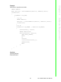
4.5.4How to dispose received messages.
DWORD dwRead;
canmsg_t ReadBuffer;
ZeroMemory(&ReadBuffer, sizeof(canmsg_t));
BOOL bSuccess = ReadFile(hDevice, &ReadBuffer, 1, &dwRead,
0);
if(bSuccess)
{
if(dwRead == 1)
{
//SUCCESS
if(ReadBuffer.flags & MSG_EXT)
{
//Extended frame
}
else{
//Standard frame
}
if(ReadBuffer.flags & MSG_RTR)
{
//Remote frame
}
if(ReadBuffer.flags & MSG_SELF)
{
55
PCI-1680U/1682U User Manual
Software Requirements
DWORD
dwWrite=0;
canmsg_t WriteBuffer;
ZeroMemory(&WriteBuffer, sizeof(canmsg_t));
WriteBuffer.flags = MSG_EXT; //Extended frame
WriteBuffer.id = 0;
WriteBuffer.length = 8;
for(int i=0; i<8; i++)
{
WriteBuffer.data[i] = i;
}
WriteFile(hDevice, &WriteBuffer, 1, &dwWrite, 0);
Chapter 4
4.5.2 How to send Extended frame, compatible with CAN 2.0B.
//self reception
}
if(ReadBuffer.flags &
{
//receive buffer
}
if(ReadBuffer.flags &
{
//CAN controller
}
if(ReadBuffer.flags &
{
//CAN controller
}
if(ReadBuffer.flags &
{
//CAN controller
}
MSG_BOVR)
overflow
MSG_BUSOFF)
bus off
MSG_OVR)
Msg overflow error
MSG_PASSIVE)
in error passive
}
else{
//Timeout
}
}
else{
DWORD dwError = GetLastError();
if (dwError == ERROR_IO_PENDING)
{
//pengding
}
else if(dwError == ERROR_INVALID_PARAMETER)
{
//parameter error
}
else if(dwError == ERROR_OPERATION_ABORTED)
{
//cancelled
}
else if(dwError == ERROR_GEN_FAILURE)
{
//bus off
}
}
See Also
canmsg_t
WriteFile
ReadFile
PCI-1680U/1682U User Manual
56
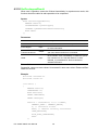
Acceptance code corresponds to 4 registers: ACR0, ACR1, ACR2, ACR3.Acceptance mask corresponds to 4 registers: AMR0, AMR1, AMR2, AMR3.ACR works with
AMR. Only when the acceptance filtering of the Standard frame or the Extended
frame is confirmed, will the filter save the data of the frame into FIFO.
Single mode
For Standard frame, 11 identifiers and the RTR bit correspond to ACR0, ACR1,
AMR0 and AMR1 with unused lower 4 bits of ACR1 and AMR1. Since the Standard
frame has 11 identifiers only, the first 2 bytes of the data field are also included for filtering.Data1 corresponds to ACR2, AMR2; Data2 corresponds to ACR3, AMR3. If
the received Standard frame is a Remote frame and the RTR bit is 1, then only the
identifier will be used for filtering.If the received Standard frame is a data frame and
the data field is less than 2 bytes, then the missed data will not be used for filtering.
For Extended frame, 29 identifiers and the RTR bit correspond to 4 ACRs and 4
AMRs. Please note that the lower 2 bits of ACR3 and AMR3 are reserved.
Example of Standard frame:
0
1(lower 4 bits)
2
3
ACR
11XXX010
XXXX
XXXXXXXX
XXXXXXXX
ACM
00111000
1111
11111111
11111111
accepted
ID(ID.10``ID.0)
11XXX010
XXX
In this example, Data1, Data2 and RTR are not considered and the accepted IDs
include: 0x7D7(11111010111), 0x610(11000010000), etc.
Example of Extended frame:
0
1
2
3
ACR
10010100
1011000X
1100XXXX
00110XXX
ACM
00000000
00000001
00001111
00000111
accepted
ID(ID.28``ID.0)
10010100
1011000X
1100XXXX
00110XXX
In this example, RTR is not considered and the accepted IDs include:
0x12961806(10010100101100001100000000110),
0x129639E6(10010100101100011100111100110), etc.
57
PCI-1680U/1682U User Manual
Software Requirements
For AMR bits,
0: the corresponding bits of ACR and CAN information frames should be the
same in order to be accepted.
1: the acceptance filtering function of the corresponding ACR bits is disabled
and the corresponding bits of the CAN information frame are independent of the
acceptance result.
Chapter 4
4.6 Acceptance filtering
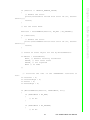
Dual Mode
Dual filtering is more complicated than single filtering. In Dual filtering mode, 4 ACRs
and 4 AMRs form two filters; the received information frame could be accepted by
either filter. For Standard frame, filter1 is composed of ACR0, ACR1, AMR0, AMR1
and the lower four bits of ACR3 and AMR3. It corresponds to 20 bits, including 11
identifiers, the RTR bit and the first byte; all of 20 bits are used for the filtering. filter2
is composed of ACR2, AMR2 and the higher four bits of ACR3 and AMR3, while only
11 identifiers and the RTR bit are used for the filtering. For Extended frame, filter1 is
composed of ACR0, ACR1, AMR0 and AMR1, not including ACR3 and AMR3.
What°Øs more, there are only 16 bits out of 29 bits used for the filtering.Filter2 is
composed of ACR2, ACR3, AMR2 and AMR3. The higher 16 bits out of 29 bits are
used for the filtering.
Example of Standard frame:
Filter1:
0
1
3 (lower 4 bits)
ACR
00000000
001XXXXX
XXXX
ACM
00000000
00011111
1111
accepted ID(ID.10``ID.0)
00000000
001
In this example, Data1 and RTR are not considered and the accepted ID: 0x1.
Filter2:
2
3 (upper 4 bits)
ACR0-ACR3
00000000
001X
ACM0-ACM3
00000000
0001
accepted ID(ID.10``ID.0)
00000000
001
In this example, RTR are not considered and the accepted ID: 0x1.
Example of Extended frame:
Filter1:
0
1
ACR
00000000
00000001
ACM
00000000
00000000
accepted ID(ID.28``ID.13)
00000000
00000001
In this example, the accepted IDs include: 0x2000(10000000000000),
0x3FFF(11111111111111), etc.
Filter2:
2
3
ACR
00000000
00000001
ACM
00000000
00000000
accepted ID(ID.28``ID.13)
00000000
00000001
In this example, the accepted IDs include: 0x2000(10000000000000),
0x3FFF(11111111111111), etc.
PCI-1680U/1682U User Manual
58
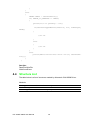
Users can directly access drivers with WINDOWS Native API. In the following, we will
provide an example by opening a CAN port and reading its current status to explain
how to write basic applications in VC, VB, VB.NET and C# environment.Necessary
files for developing applications are listed below. Suppose installation paths of all
header files in the example are C:\Program Files\ADVANTECH\AdvCAN\Include.
Description
AdvCan.h
Header file for VC
AdvCan.cs
Header file for C#
AdvCan.vb
Header file for VB.NET
AdvCan.bas
Header file for VB
Note!
Users who use CAN driver on windows CE can directly refer to Structure
list and Introduction to API (GetOverlappedResult is not included).
4.7.1 Guide for Visual C++ development
We will give an example by opening a CAN port and reading its current status so as
to simply explain how to write base applications in Visual C++ environment.
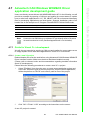
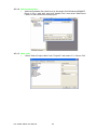
4.7.1.1 Create a new VC project
Related header files must be used before using Advantech CAN Windows WDM&CE
Driver interface function. Make sure the driver had been installed correctly.
(Please refer to relevant books and documentations regarding detailed information
about VC development.)
Please follow the following procedures to create a new VC++ project:
1. Select "File/New" from the main menu to create a new application project and
source file. Define the type pf the new project as "Win32 Console Application",
define the platform as "Win32" and select a path for files of the project.
2.
Click "OK"->"Finish"->"OK" according to the instructions on the screen.
A new VC project is created.
59
PCI-1680U/1682U User Manual
Software Requirements
File name
Chapter 4
4.7 Advantech CAN Windows WDM&CE Driver
application development guide
4.7.1.2 Add necessary files
1. Add Include header files (AdvCan.h) in Advantech CAN Windows WDM&CE
Driver. In VC++ work area, right click "Header Files", then select "Add Files to
Folder" to add header files to the project.
4.7.1.3 Write code
1. “Select "Add to Project->New" from "Project"£¨ then select "C++ Source File".
PCI-1680U/1682U User Manual
60
// Get Can port status.
flag = DeviceIoControl( hDevice,
CAN_IOCTL_STATUS,
NULL,
0,
&CanStatus,
sizeof(CanStatusPar_t),
&dwReturned,
0
);
if ( !flag )
{
printf( "GetStatus Error!");
return;
}
printf( "Acceptance code = 0x%x\n" , CanStatus.acceptancecode
);
printf( "Acceptance mask = 0x%x\n" , CanStatus.acceptancemask
);
printf(
printf(
printf(
printf(
"Baud = %u\n", CanStatus.baud );
"Self reception = %u\n" , CanStatus.selfreception );
"Read time out = %u\n" , CanStatus.readtimeout );
"Write time out = %u\n" , CanStatus.writetimeout );
//Close port handle
flag =CloseHandle(hDevice);
if ( !flag )
{
printf( "Close Error!");
return;
}
}
61
PCI-1680U/1682U User Manual
Software Requirements
void main()
{
HANDLE hDevice = NULL;
CanStatusPar_t CanStatus;
BOOL flag;
ULONG dwReturned;
//Open Can Port "CAN1".
//You can also change "CAN1" to a port name which you have
installed.
hDevice = CreateFile("\\\\.\\can1",
GENERIC_READ | GENERIC_WRITE,
0,
NULL,OPEN_EXISTING,
0,
NULL);
if ( hDevice == INVALID_HANDLE_VALUE )
{
printf( "Open Can Port Error!" );
return;
}
Chapter 4
Write code in empty source file.
#include <stdio.h>
#include <windows.h>
#include "C:\Program Files\Advantech\AdvCan\Include\AdvCan.h"
4.7.1.4 Test application
Run the application, the following result will be displayed.
4.7.2 Guide for Visual Basic development
We will give an example by opening a CAN port and reading its current status so as
to simply explain how to write base applications in Visual Basic environment.
4.7.2.1 Create a new VB project
Related header files must be used before using Advantech CAN Windows WDM&CE
Driver interface function. Make sure the driver had been installed correctly.
(Please refer to relevant books and documentations regarding detailed information
about VB development.)
Please follow the following procedures to create a new VB project:
1. Select "File"->"New Project" from the main menu. For Project Types, select
Standard EXE.
A new VB project is created.
PCI-1680U/1682U User Manual
62
Chapter 4
4.7.2.2 Add files and design graphical interfaces
1. Add Include header files (AdvCan.bas) in AdvCAN Windows WDM&CE Driver.
Right click the project and select Add->Module Item,then select Existing Item to
add AdvCan.bas.(Installation path\AdvCan\Include\AdvCan.bas)
Software Requirements
63
PCI-1680U/1682U User Manual
2.
Design graphical interfaces. Add one Button and six Text controls to Form1.
4.7.2.3 Write code
1. Write corresponding code for Button1.
Private Sub Button1_Click()
Dim hDevice As Long
Dim Status As CanStatusPar_t
Dim result As Boolean
Dim dwOutLen As Long
Dim ov As OVERLAPPED
'Open Can Port "CAN1".
'You can also change "CAN1" to a port's name which you
have installed.
hDevice = CreateFile("\\.\can1", GENERIC_READ +
GENERIC_WRITE, 0&, 0&, OPEN_EXISTING, FILE_ATTRIBUTE_NORMAL
+ FILE_FLAG_OVERLAPPED, 0&) 'Open the CAN port in synchronous
mode
If hDevice = &HFFFFFFFF Then
MsgBox ("Open Error!")
Exit Sub
End If
'Get Can port status.
result = DeviceIoControl(hDevice, CAN_IOCTL_STATUS, Nothing, 0&, Status, Len(Status), dwOutLen, 0&)
If Not result Then
MsgBox ("GetStauts Error!")
Exit Sub
PCI-1680U/1682U User Manual
64
65
PCI-1680U/1682U User Manual
Software Requirements
4.7.2.4 Test application
Run the application, the following result will be displayed.
Chapter 4
End If
TextBox1.Text = "Baud rate= " + CStr(Status.baud)
TextBox2.Text = "Accept code = " + Hex(Status.acceptancecode)
TextBox3.Text = "Mask code = " + Hex(Status.acceptancemask)
TextBox4.Text = "Self recevie = " + CStr(Status.selfreception)
TextBox5.Text = "Read TimeOut = " + CStr(Status.ReadTimeOut)
TextBox6.Text = "Write TimeOut: = " + CStr(Status.WriteTimeOut)
result = CloseHandle(hDevice) 'Close the CAN port
If Not result Then
MsgBox ("Failed to close the CAN port!")
End If
End Sub
4.7.3 Guide for VC.NET development
We will give an example by opening a CAN port and reading its current status so as
to simply explain how to write base applications in VC.NET environment.
4.7.3.1 Create a new VC.NET project
Related header files must be used before using Advantech CAN Windows WDM&CE
Driver interface function. Make sure the driver had been installed correctly.
(Please refer to relevant books and documentations regarding detailed information
about VC.NET development.)
Please follow the following procedures to create a new VC.NET project:
1. Select "File/New->Project" from the main menu to create a new application
project and source file. Define the type of the new project as "Windows Forms
Application", and select a path for files of the project.
2.
Click "OK" according to the instructions on the screen.
A new VC.NET project is created.
4.7.3.2 Add necessary files
1. Add Include header files (AdvCan.h) in Advantech CAN Windows WDM&CE
Driver. In VC.NET work area, right click "Header Files" and select "Add ->Existing Item" to add header files to the project in the "Add Existing Item - Test" file
list.
PCI-1680U/1682U User Manual
66
Chapter 4
Design graphical interfaces. Add one Button and six Text controls to Form1.
67
PCI-1680U/1682U User Manual
Software Requirements
2.
4.7.3.3 Write code
Write code in source file.
#include <windows.h>
#include "../../../Include/AdvCan.h"
private: System::Void button1_Click(System::Object^ sender,
System::EventArgs^ e)
{
HANDLE hDevice = 0;
BOOL result;
int dwOutLen=0;
int lpSecurityAttributes=0;
OVERLAPPED ov ;
CanStatusPar_t CanStatus;
Command_par_t cmd ;
//Open Can Port "CAN1".
//You can also change "CAN1" to a port's name which you have
installed.
System::String^ CanPortName = "\\\\.\\" + "can1";
TCHAR*
LWCanPortName=
static_cast<TCHAR*>(System::Runtime::InteropServices::Marshal::StringToCoTaskMemAuto(
CanPortName).ToPointer());
hDevice
=
CreateFile(
LWCanPortName,GENERIC_READ
|
GENERIC_WRITE,0,(LPSECURITY_ATTRIBUTES)lpSecurityAttributes,OPEN_EXISTING,
FILE_ATTRIBUTE_NORMAL|FILE_FLAG_OVERLAPPED,NULL);
if( (unsigned int)hDevice == 0xffffffff )
{
MessageBox::Show("Open CAN port Error!");
return;
}
//Get Can port status.
result
=
DeviceIoControl(
vice,(ULONG)CAN_IOCTL_STATUS,&cmd,0,&CanStatus,sizeof(CanStatusPar_t),(LPDWORD)&dwOutLen,&ov);
if( !result )
{
MessageBox::Show("GetStauts Error!");
return;
}
hDe-
this->textBox1->Text
=
"Baud
rate
=
"
+
CanStatus.baud.ToString();
this->textBox2->Text = "Accept code = " + CanStatus.acceptancecode .ToString("X2");
this->textBox3->Text = "Mask code = " + CanStatus.acceptancemask .ToString("X2");
this->textBox4->Text = "Self recevie = " + CanStatus.selfreception .ToString();
this->textBox5->Text = "Read TimeOut = " + CanStatus.readtimeout .ToString();
this->textBox6->Text = "Write TimeOut= " + CanStatus.writetimeout .ToString();
result = CloseHandle( hDevice ); //Close the CAN port
if (! result )
{
MessageBox::Show ("GetStauts Error!");
return;
}
}
PCI-1680U/1682U User Manual
68
Chapter 4
4.7.3.4 Test application
Run the application, the following result will be displayed.
Software Requirements
4.7.4 Guide for for VB.NET development
We will give an example by opening a CAN port and reading its current status so as
to simply explain how to write base applications in VB.NET environment.
4.7.4.1 Create a new VB.NET project
Related header files must be used before using Advantech CAN Windows WDM&CE
Driver interface function. Make sure the driver had been installed correctly.
(Please refer to relevant books and documentations regarding detailed information
about VB.NET development.)
69
PCI-1680U/1682U User Manual
Please follow the following procedures to create a new VB.NET project:
1. Select "File"->"New"->"Project" from the main menu. For Project Types, select
Visual Basic Projects. Templates is Windows Application.
A new VB.NET project is created.
4.7.4.2 Add files and design graphical interfaces
1. Add Include header files (AdvCan.vb) in AdvCAN Windows WDM&CE Driver.
Right click the project, then select Add->Add Existing Item to add AdvCan.vb.
(Installation path\AdvCan\Include\AdvCan.vb)
PCI-1680U/1682U User Manual
70
Design graphical interfaces. Add one Button and six Text controls to Form1.
'Open Can Port "CAN1".
'You can also change "CAN1" to a port's name which you
have installed.
hDevice = CreateFile("\\.\can1", GENERIC_READ +
GENERIC_WRITE,
0,
Nothing,
OPEN_EXISTING,
FILE_ATTRIBUTE_NORMAL + FILE_FLAG_OVERLAPPED, 0)
If hDevice.ToInt32 = &HFFFFFFFF Then
MsgBox("Open Error!")
Exit Sub
End If
'Get Can port status.
result = DeviceIoControl(hDevice, CAN_IOCTL_STATUS, Nothing, 0, status, Len(status), dwOutLen, ov)
If Not result Then
MsgBox("GetStauts Error!")
Exit Sub
End If
TextBox1.Text = "Baud rate= " & status.baud
71
PCI-1680U/1682U User Manual
Software Requirements
4.7.4.3 Write code
1. Write corresponding code for Button1.
Private Sub Button1_Click(ByVal sender As System.Object,
ByVal e As System.EventArgs) Handles Button1.Click
Dim hDevice As IntPtr
Dim status As CanStatusPar_t
Dim result As Boolean
Dim dwOutLen As Integer
Dim ov As New OVERLAPPED
Chapter 4
2.
TextBox2.Text = "Accept code = " & Hex(status.acceptancecode)
TextBox3.Text = "Mask code = " & Hex(status.acceptancemask)
TextBox4.Text = "Self recevie = " & status.selfreception
TextBox5.Text = "Read TimeOut = " & status.readtimeout
TextBox6.Text = "Write TimeOut: = " & status.writetimeout
result = CloseHandle(hDevice) 'Close the CAN port
If Not result Then
MsgBox("Failed to close the CAN port!")
End If
End Sub
4.7.4.4 Test application
Run the application, the following result will be displayed.
PCI-1680U/1682U User Manual
72
We will give an example by opening a CAN port and reading its current status so as
to simply explain how to write base applications in C# environment.
2.
Type the name and saving path of the project according to instructions on the
screen, and click "OK".
A new C# project is created.
73
PCI-1680U/1682U User Manual
Software Requirements
4.7.5.1 Create a new C# project
Related header files must be used before using Advantech CAN Windows WDM&CE
Driver interface function. Make sure the driver had been installed correctly.
(Please refer to relevant books and documentations regarding detailed information
about C# development.)
Please follow the following procedures to create a new C# project:
1. Select "File"->"New"->"Project" from the main menu. For Project Types, select
Visual C# Projects. Templates is Windows Application.
Chapter 4
4.7.5 Guide for C# development
4.7.5.2 Add files and design graphical interfaces
1. Add Include header files (AdvCan.cs) in Advantech CAN Windows WDM&CE
Driver.
Right click the project, then select Add->Add Existing Item to add AdvCan.cs.
(Installation path\AdvCan\Include\AdvCan.cs)
PCI-1680U/1682U User Manual
74
Design graphical interfaces. Add one Button and six TextBox controls to Form1.
Chapter 4
2.
Software Requirements
75
PCI-1680U/1682U User Manual
4.7.5.3 Write code
1. Add the following code to Button:
private void button1_Click(object sender, System.EventArgs e)
{
uint hDevice = 0;
bool result;
int dwOutLen=0;
int lpSecurityAttributes=0;
AdvCan.OVERLAPPED ov =new AdvCan.OVERLAPPED();
AdvCan.CanStatusPar_t CanStatus = new AdvCan.CanStatusPar_t();
AdvCan.Command_par_t cmd =new AdvCan.Command_par_t ();
//Open Can Port "CAN1".
//You can also change "CAN1" to a port's name which you have
installed.
hDevice = AdvCan.CreateFile("\\\\.\\can1",AdvCan.GENERIC_READ +
AdvCan.GENERIC_WRITE,
0,
lpSecurityAttributes,
AdvCan.OPEN_EXISTING,
AdvCan.FILE_ATTRIBUTE_NORMAL
+
AdvCan.FILE_FLAG_OVERLAPPED, 0);
if( hDevice == 0xffffffff )
{
MessageBox.Show("Open CAN port Error!");
return;
}
//Get Can port status.
result
=
AdvCan.DeviceIoControl(hDevice,
AdvCan.CAN_IOCTL_STATUS,ref cmd, 0,ref CanStatus,Marshal.SizeOf (CanStatus),ref dwOutLen,ref ov);
if( !result )
{
MessageBox.Show("GetStauts Error!");
return;
}
textBox1.Text = "Baud rate = " + CanStatus.baud .ToString();
textBox2.Text = "Accept code = " + CanStatus.acceptancecode
.ToString("X2");
textBox3.Text = "Mask code = " + CanStatus.acceptancemask
.ToString("X2");
textBox4.Text = "Self recevie = " + CanStatus.selfreception
.ToString();
textBox5.Text = "Read TimeOut = " + CanStatus.readtimeout
.ToString();
textBox6.Text = "Write TimeOut= " + CanStatus.writetimeout
.ToString();
result = AdvCan.CloseHandle( hDevice ); //Close the CAN port
if (! result )
{
MessageBox.Show ("GetStauts Error!");
return;
}
}
PCI-1680U/1682U User Manual
76
Chapter 4
4.7.5.4 Test application
Run the application, the following result will be displayed.
Advantech CAN Windows WDM&CE Driver package contains examples of VC, VB,
VB.NET, C#.NET, VC.NET, eVC. Users can refer to these examples to develop applications.
WDM:
Example Name Description
VC
VB
VB.NET C#.NET VC.NET
Can Configure
This example shows how to
configure each item of CAN
port.
Yes
Yes
Yes
Yes
Yes
Can Send
This example shows how to
send data to CAN port.
Yes
Yes
Yes
Yes
Yes
Can Receive
This example shows how to
receive data from CAN port.
Yes
Yes
Yes
Yes
Yes
Can Event
This example shows how to
receive/send data from/to CAN
port through events in the way Yes
similar to serial port communication.
Yes
Yes
Yes
Yes
77
PCI-1680U/1682U User Manual
Software Requirements
4.8 Examples
CE:
VB.NE
T
Example Name
Description
C#.NET VC.NET eVC
Can Configure
This example shows how to configure
Yes
each item of CAN port.
Yes
Yes
Yes
Can Send
This example shows how to send
data to CAN port.
Yes
Yes
Yes
Yes
Can Receive
This example shows how to receive
data from CAN port.
Yes
Yes
Yes
Yes
Can Event
This example shows how to receive/
send data from/to CAN port through
Yes
events in the way similar to serial port
communication.
Yes
Yes
Yes
4.8.1 Interface
4.8.1.1 Send
Data is sent. Values of Baud Rate and timeout of the port can be set. Meanwhile, self
reception function will be realized.
Please refer to Send flow chart for function calling.
Before you begin, please enter the name of the port you have installed in combobox
of CAN Port, such as can0, can1, etc. The user can choose either Standard or Custom to set Baud Rate. If Standard is chosen, you should select the Baud Rate needs
to be set from the dropdown list of Baud Rate.If the user chooses Custom, you
should write values of BTR0 and BTR1 manually in the textbox. The default values of
both are 125k. Type value of timeout in Timeout filed (The default value is 3000 ms).
Selecting RTR check box can realize RTR function.Selecting Self Reception check
box can realize self reception function.On WDM platform, the user can select either
synchronous mode or asynchronous mode. While on CE platform, only synchronous
mode is supported.After configuring the above items, users can click "Start" button to
send data .
After clicking "Start" button, the name of the button will change into "Stop". At the
same time, results of sent frames will be shown in the textbox on the right. Users can
click "Stop" button to stop sending frames during the process, then the name of the
button will return to "Start" for the next send operation.
PCI-1680U/1682U User Manual
78
CE
Software Requirements
WDM
Chapter 4
79
PCI-1680U/1682U User Manual
4.8.1.2 Receive
Data is received. Values of Baud Rate and timeout of the port can be set.
Please refer to Receive flow chart for function calling.
Before you begin, please enter the name of the port you have installed in combobox
of CAN Port, such as can0, can1, etc. The user can choose either Standard or Custom to set Baud Rate. If Standard is chosen, you should select the Baud Rate needs
to be set from the dropdown list of Baud Rate.If the user chooses Custom, you
should write values of BTR0 and BTR1 manually in the textbox. The default values of
both are 125k. Type value of timeout in Timeout filed (The default value is 3000
ms).On WDM platform, the user can select either synchronous mode or asynchronous mode. While on CE platform, only synchronous mode is supported.After configuring the above items, users can click "Start" button to receive data.
After clicking "Start" button, the name of the button will change into "Stop". At the
same time, results of received frames will be shown in the textbox on the right. Users
can click "Stop" button to stop receiving frames during the process, then the name of
the button will return to "Start" for the next receive operation.
WDM
CE
PCI-1680U/1682U User Manual
80
This is only used to change configuration of the application which is currently running. Once "Configure" item is closed, all changes made in it
will not be retained.
WDM
81
PCI-1680U/1682U User Manual
Software Requirements
Note!
Chapter 4
4.8.1.3 Configure
Users can set values of Baud Rate, Timeout of sending and receiving data, mask of
receive register and filter. Meanwhile, status of the port can be displayed.
Please refer to Configure flow chart for function calling.
Before you begin, please select the name of the port you have installed in combobox
of CAN Port, such as can0, can1, etc. Select value of Baud Rate that you want in
dropdown list of Baud Rate (The default value is 125 k). Select Single or Dual of
Acceptance FIlter Mode. Enter filter mask for receiving data in the fields of Acceptance Mask and Acceptance Code (The default value is 0xFFFFFFFF). Type values
of timeout in Write Timeout and Read Timeout fields (The default value is 3000 ms).
After configuring the above items, users can click "Configure" button to change the
current setting of the port.
After clicking "Configure" button, successful message and the new configuration
information will be displayed if you succeed in configuring. In addition, number of
received data and values of controllers will be displayed as well. If the configuration
fail, prompting message will be dispalyed.
CE
4.8.1.4 Event
This function is similar to serial port communication, which send/receive data through
events. Baud Rate and timeout values in the example are fixed. The application realizes duplex communication.
Please refer to Event flow chart for function calling.
Before you begin, please select the name of the port you have installed in combobox
of CAN Port, such as can0, can1, etc. Value of Baud Rate is fixed at 125 k, and
Value of timeout is fixed at 3000 ms. The user can select RTR check box can realize
RTR function. After configuring the above items, users can click "Start" button to
send/receive data .
After clicking "Start" button, the name of the button will change into "Stop". At the
same time, results of sent/received results will be shown in both textboxes. The two
ports are using duplex communication. Users can click "Stop" button to stop sending/
receiving frames during the process, then the name of the button will return to "Start"
for the next send/receive operation.
WDM
PCI-1680U/1682U User Manual
82
CE
Chapter 4
Software Requirements
4.8.2 Flow Chart
4.8.2.1 Send flow chart
83
PCI-1680U/1682U User Manual
4.8.2.2 Receive flow chart
PCI-1680U/1682U User Manual
84
Chapter 4
4.8.2.3 Configure flow chart
Software Requirements
85
PCI-1680U/1682U User Manual
4.8.2.4 Event flow chart
Either flow chart of the two sub threads is as below:
PCI-1680U/1682U User Manual
86
System Requirements
Windows 2000, 32-bit Windows XP, 32-bit Windows Vista, 32-bit Windows 7, 64-bit
Windows XP, 64-bit Windows Vista, 64-bit Windows 7.
87
PCI-1680U/1682U User Manual
Software Requirements
An Utility is provided for users to test whether hardware is working normally.
It's installed under C:\Program Files\Advantech\AdvCAN\Utility directory by default.
This Utility can be divided into four parts:
In Part 1, users can select which port to open in the choice box at top.Set "Baud
Rate", "acceptance filter mode", "acceptance code", "acceptance Mask", and choose
if you want to receive "Self Reception" or send "RTR".Users can select "Listen Only"
if you want use listen only mode.can also set "Cycle" of data transfer by entering the
interval time (ms).Users can select "Auto Increase" if you want the data increase
automatically.When setting is finished, users can choose to Open/Close the port,
Start Tx/Stop Tx and Start Rx/Stop Rx.
In Part 2, detail information of received data will be shown when communication is
built.
In Part 3, the following items will be shown:Numbers of sent frames, timeout sent
frames, received frames and timeout received frames.Times of entering PASSIVE
error mode, times of entering BUS OFF mode, times of hardware OVERRUN and
times of software OVERRUN (BOVERRUN) .Users can select ASCII mode. As a
result, ASCII format of the data will be shown in Part 2.
In Part 4, ID, Flag (SFF: Standard Frame; EFF: Extended Frame), length and data of
messages will be configured before being sent.
Chapter 4
4.9 Use Utility to test hardware
4.10 CANMonitor
CANMonitor can be used to monitor the messages in CAN network and to show the
messages according to different message types. CANMonitor can show messages in
the formats of CAN and CANopen.
System Requirements
Windows 2000, 32-bit Windows XP, 32-bit Windows Vista, 32-bit Windows 7, 64-bit
Windows XP, 64-bit Windows Vista, 64-bit Windows 7.
PCI-1680U/1682U User Manual
88
This section introduces the functions that CANMonitor supports.
Base function:
Open Device
Opens a device and make basic configuration.
Close Device
Closes a device and clear all the data.
Load from file
Loads data from the file.
Save to file
Saves data to the specified file.
Restarts communication based on the configuration .
Stop Communication
Stops communication, which is used to view data when the refresh
is frequent.
Show Message
Shows messages.
Hide Message
Hides messages.
Clear Data
Clears all data.
Auto Scroll
Supports auto scroll function.
Goto
Goes to the specified message line.
Listen only mode
Supports Listen Only mode.
CAN Message Filter
Configures CAN message filter modes.
CAN Message View
Shows CAN format message.
CANopen function:
List Node
Lists CANopen nodes detected and the node state.
Change Node State
Changes the specified CANopen node state.
Read Data from Node
Reads data from the specified CANopen node .
Write Data to Node
Writes data to the specified CANopen node.
Detect All Nodes in
CANopen
Detects all the possible CANopen nodes, from 1 to 127.
CAN Message Filter
Configures CAN message filter modes.
CANopen Message FilConfigures CANopen message filter modes.
ter
CAN Message View
Shows CAN format message.
CANopen Message
View
Shows CANopen format message.
89
PCI-1680U/1682U User Manual
Software Requirements
Start Communication
Chapter 4
4.10.1 Function Introduction
4.10.2 Introduction to Main Items in Menu Screen
Menu Introduction
File
File has the following functions:
Name
Function
New
Open device
Close
Close device
Load
Load data from File
Save
Save data to File
Exit
Exit the program
View
View has the following functions:
Name
Function
Toolbar
Whether to show the toolbar
Status Bar
Whether to show the status bar
Auto Scroll
Whether to scroll automatically
Clear
Clear all the messages
Goto
Go to the specified line
PCI-1680U/1682U User Manual
90
Chapter 4
Data Format
Data Format has following setting:
Function
Hex
The monitor data which includes "ID" and "Data" will be displayed as Hex format.
Dec
The monitor data which includes "ID" and "Data" will be displayed as Dec format.
Ascii
The monitor "Data" will be displayed as Dec format but "ID" will be displayed as
Hex format
Function
Function has the following functions:
Name
Function
Run
Start communication
Stop
Stop communication
Show
Show the message
Hide
Hide the message
Listen
Only Whether to open Listen Only mode
CAN
CAN has a submenu:
Name
Function
Send CAN Message
Send CAN Message
91
PCI-1680U/1682U User Manual
Software Requirements
Name
CANopen
CANopen has the following functions:
Name
Function
List Node
List all CANopen nodes
Change Node
State Change CANopen node state
Read Object
Read CANopen node data
Write Object
Write CANopen node data
Node Guard All
Get all CANopen nodes
Filter
Filter has CAN Filter setting
and CANopen Filter setting.
PCI-1680U/1682U User Manual
92
Name
Function
New
Open device
Chapter 4
Toolbar Introduction
Close Device
Load
Load data from file
Save
Save data to file
Run
Start communication
Stop
Stop communication
Show
Show the message
Hide
Hide the message
Auto
Scroll Whether to scroll automatically
Clear
Clear all the messages
Status Bar Introduction
Name
Function
S1
Show the load; the two formats - Kbit/s and bit/s will be selected automatically
S2
Show the current status of the device: Normal, Passive, Bus off
S3
Show the number of the messages sent
S4
Show the number of the messages received
S5
Show the number of Overrun
S6
Show the number of lines of the data; the maximum number will not exceed the
number configured when the device is open
93
PCI-1680U/1682U User Manual
Software Requirements
Close
4.11 COTI.DLL for CANopen Conformance Test
The COTI DLL allows users to use the CANopen Conformance Test Tool of CiA(CAN
in Automation) with Advantech CAN WDM Driver.This file has to be copied into the
directory of the CANopen Conformance Test.More detailed presentation about CANopen Conformance Test Tool, please refer to:
http://www.can-cia.org/index.php?id=141.
The default installation path for COTI.DLL is C:\Program Files\Advantech\AdvCAN\COTI.
System Requirements
Windows 2000, 32-bit Windows XP, 32-bit Windows Vista.
PCI-1680U/1682U User Manual
94
Chapter
5
5
Pin Assignments and
Wiring
This chapter covers the pin
assignment for the CAN connector, and the wiring of the two
transmission wires.
Sections include:
Pin Assignments
Wiring
5.1 Pin Assignments
Figure 5.1 shows the pin assignment for the card's DB-9 connectors:
Figure 5.1 PCI-1680U/1682U DB-9 pin assignment
5.2 Wiring
The CAN standard supports half-duplex communication. This means that just two
wires are used to transmit and receive data.
Table 5.1: PCI-1680U/1682U Pin Wiring and Description
PCI-1680U/1682U DTE (male DB-9)
Terminal DTE
Pin
Signal
Signal
2
CAN_L
CAN_L
3
GND
GND
7
CAN_H
CAN_H
PCI-1680U/1682U User Manual
96
Chapter 5
Pin Assignments and Wiring
PCI-1680U/1682U User Manual
97
www.advantech.com.cn
Please verify specifications before quoting. This guide is intended for reference
purposes only.
All product specifications are subject to change without notice.
No part of this publication may be reproduced in any form or by any means,
electronic, photocopying, recording or otherwise, without prior written permission of the publisher.
All brand and product names are trademarks or registered trademarks of their
respective companies.
© Advantech Co., Ltd. 2010