1
Ä.>_Uä
SHPPLCDCAN
13296252
L-force Engineering
Software Manual
PC-based Automation
PLC Designer - CANopen for Runtime Systems
L
L-force | PLC Designer - CANopen for Runtime Systems
Content
1
2
About this documentation ___________________________________________ 3
1.1
Document history ____________________________________________ 3
1.2
Liability ____________________________________________________ 3
1.3
Trademarks ________________________________________________ 4
1.4
CANopen terms and Lenze implementation________________________ 4
CANopen-Master library ____________________________________________ 5
2.1
Differentiation from other CANopen libraries _______________________ 5
2.2
CANopen for the user_________________________________________ 6
2.3
2.4
3
4
2.2.1
Used modules________________________________________ 6
2.2.2
How to create a project with CANopen_____________________ 7
Functionality of the libraries at runtime____________________________ 9
2.3.1
Implicit services of the CANopen-Master library______________ 9
2.3.2
Explicit services of the CANopen library___________________ 10
2.3.3
Starting the CANopen network __________________________ 10
Working with the CANopen-Master part in the application ____________ 11
2.4.1
Structure of the CANopen-Master _______________________ 11
2.4.2
Structure of the CANopen-node (Slave) ___________________ 14
2.4.3
Interpretation and reaction on the states of the library ________ 16
2.4.4
Examples for application-controlled actions of the libraries ____ 20
2.5
Implicit calls _______________________________________________ 27
2.6
Object dictionary of the CANopen-Master ________________________ 27
CanDevice ______________________________________________________ 29
3.1
Functionality _______________________________________________ 29
3.2
Configure CanDevice ________________________________________ 30
3.3
CanDevice Settings _________________________________________ 31
3.4
Generate EDS-file __________________________________________ 33
3.5
Modifying the default mapping by the master configuration ___________ 37
3.6
Working with the CanDevice in the application program _____________ 38
3.6.1
Module CanopenDevice _______________________________ 38
3.6.2
Access on the object dictionary entries by the application
program ___________________________________________ 41
3.6.3
Changing the PDO properties at runtime __________________ 41
3.6.4
Sending emergency messages by the application program ____ 42
CAN network variables ____________________________________________ 43
DMS 2.0 EN 05/2009 TD29
1
L-force | PLC Designer - CANopen for Runtime Systems
4.1
5
2
CAN network variables for the user _____________________________ 43
4.1.1
Preconditions _______________________________________ 43
4.1.2
Target Settings ______________________________________ 43
4.1.3
Settings in the Global Variables Lists _____________________ 44
4.1.4
Generated calls _____________________________________ 46
Appendix _______________________________________________________ 47
5.1
List of SDOs usually created for a slave__________________________ 47
5.2
Monitoring transmit buffer overruns _____________________________ 47
5.3
FAQs – Frequently Asked Questions ____________________________ 48
5.3.1
CANopen Functionality________________________________ 48
5.3.2
CANopen Master ____________________________________ 52
5.3.3
Application _________________________________________ 53
5.3.4
Possible Errors, Error causes and Solutions _______________ 53
DMS 2.0 EN 05/2009 TD29
L-force | PLC Designer - CANopen for Runtime Systems
About this documentation
1
About this documentation
This document consists of three partitions: The first one describes the CANopen-Master library, the
second describes the CANopen-Slave-library and there is a separate chapter for the CAN network
variables.
The library descriptions each are structured as follows:
-
Overview on the features of the library.
-
Description of the default steps for working with the library.
-
Description of the possibilities which the application has to influence the CAN stack and to get
information from the stack.
-
Overview on possible error states and their causes.
Target group
This documentation addresses to qualified personnel in accordance with IEC 364.
Information on the validity
The information in this documentation is valid for the following Lenze software:
Software
From software version
L-force »PLC Designer«
2.2.0.7
1.1
Document history
Version
Description
1.0
08/2008
TD29
First edition
2.0
05/2009
TD29
Revision
1.2
Liability
All information given in this documentation has been selected carefully and tested for compliance with
the hardware and software described. Nevertheless, discrepancies cannot be completely ruled out.
We do not accept any responsibility or liability for any damage that may occur. Required corrections
will be included in updates of this documentation.
This documentation is based on the original »CoDeSys« documentation by the company 3S - Smart
Software Solutions GmbH (Kempten). The screenshots shown may deviate from the »PLC Designer«
representation.
DMS 2.0 EN 05/2009 TD29
3
L-force | PLC Designer - CANopen for Runtime Systems
About this documentation
1.3
Trademarks
Microsoft, Windows and Windows NT are either registered trademarks or trademarks of Microsoft
Corporation in the U.S.A. and/or other countries.
Adobe and Reader are either registered trademarks or trademarks of Adobe Systems Incorporated in
the U.S.A. and/or other countries.
All other product names contained in this online documentation are trademarks of the corresponding
owners.
1.4
CANopen terms and Lenze implementation
According to CANopen in a CAN network there are no masters and slaves.
According to CANopen there is a NMT-Master, a configuration master etc., always keeping in mind,
that all participants in a CAN network have equal rights.
The Lenze implementation proceeds on the assumption that a CAN network serves as periphery of a
»PLC Designer«-programmable controller. As a consequence »PLC Designer« in the CAN
configurator names a PLC “CAN-Master”. This master is NMT-master and configuration master.
Normally the PLC will mind that the network can be taken into operation. The master starts the
particular nodes which are known to it via the configuration. These nodes are named “slaves”.
In order also to approach the master to the status of a CANopen-node, an object dictionary for the
master was introduced. The master also can act as a SDO server, not anymore only as a SDO-Client
in the configuration phase of the slave. (Further details in a later chapter.)
4
DMS 2.0 EN 05/2009 TD29
L-force | PLC Designer - CANopen for Runtime Systems
CANopen-Master library
2
CANopen-Master library
2.1
Differentiation from other CANopen libraries
The library implemented by Lenze differs in several respects from other systems available on the
market. It has not been developed to make abundant other libraries which are provided by prestigious
manufacturers, but pointedly has been optimized for the use with the »PLC Designer« programming
and runtime systems.
The libraries are made according to the CiA DS301, V401 specification.
For users of the »PLC Designer«-CANopen-library the following advantages result:
• The implementation is independent from the target system and so usable on every »PLC
Designer«-compatible PLC without changes.
• The customer gets a complete system from one distributor. This means, the configurator and the
embedding of the CANopen-protocol into the runtime system are optimally coordinated.
• The CANopen-functionality is loadable.
This means, the CANopen-functions can be reloaded and updated without changing the runtime
system.
• The resources are used carefully. Memory is allocated depending on the used configuration, not
for a maximum configuration.
• Automatic IO-update without additional measures.
The following functionalities, defined by CANopen, are supported by the CANopen-library of Lenze
(May 2005):
• Sending PDOs from the master => to the slaves
Event-controlled (on change) and as synchronous PDOs, i.e. always after a certain number of
Sync messages has gone over the bus (the number is defined by the Transmission Type of the
PDO in the CAN configurator) the PDO will be sent by the master. Also an external Sync-source
can be used in order to initiate the sending of synchronous PDOs.
The time-controlled transmission of individual PDOs can only be implemented in the »PLC
Designer« by means of a program written in the IEC61131 code. For this purpose a task with a
corresponding cycle time is created containing the program for the transmission. The settings for
the event time made in the “PDO properties" dialog will not be taken into account. We recommend
to use the “cyclic-synchronous” transmission mode and to specify the sync triggering the
transmission of the PDO. See also page 8.
• Receiving PDOs from the slave => to the master.
Dependent on the slaves: event-controlled, request-controlled, acyclic and cyclic.
• PDO mapping
if supported by the slaves.
• SDO sending and receiving (unsegmented, i.e. 4 bytes per object dictionary entry)
Automatic configuration of all slaves via SDOs at system start
Application-controlled sending and receiving of SDOs to configured slaves.
• Synchronisation
Automatic sending of sync messages by the CANopen-Master.
• Nodeguarding
Automatic sending of guarding messages and guarding the lifetime for each correspondingly
configured slave.
DMS 2.0 EN 05/2009 TD29
5
L-force | PLC Designer - CANopen for Runtime Systems
CANopen-Master library
• Heartbeat
Automatic sending and guarding of heartbeat messages.
• Emergency
Receiving and storing of emergency messages from the configured slaves.
• The direct communication between slaves via PDOs is possible, but must be configured
„manually“.
The following functions defined in CANopen are currently not supported by the Lenze CANopen library
(State: May 2005):
• Dynamic identifier assignment
• Dynamic SDO connections
• Blockwise SDO transfer
• The guarding of more than one heartbeat from the CAN Device viewpoint.
• Network variables according to CANopen specification DS302
• Modules according to DS405.
• All possibilities of the CANopen protocol not mentioned above
2.2
2.2.1
CANopen for the user
Used modules
To realize the CANopen-library easily and practically, the following modules are necessary:
For a simple and practical realization of the CANopen function under a »PLC Designer«
programmable PLC the following modules are required:
• A »PLC Designer« programming system, as from version V2.3 SP5, with integrated CANopenconfigurator.
• The STANDARD.LIB, providing the standard functions defined in IEC-61131 for the PLC.
• In »PLC Designer« programmable multitasking systems the libraries SysLibSem.lib (semaphores
for the exclusive processing of certain code sections) and SysLibCallback.lib (IEC-function calls at
certain events) are used to get a multitasking-save access on CAN.
• EDS-files for all slaves which are part of the network. The EDS-files are provided by the hardware
manufacturer of the CANopen-Slaves.
• The library 3S_CANDRV.Lib, realizing the CAN base functions. The library is hardware-dependent
and must be available as external (or internal) »PLC Designer« library.
This library usually is provided by the PLC manufacturer and has a uniform interface to
3S_CANOPEN.lib.
• The library 3S_CanOpenManager.Lib, providing the CANopen base functionalities.
• One or several of the libraries 3S_CanOpenNetVar,
3S_CanOpenMaster. Depends on the desired functionality.
6
DMS 2.0 EN 05/2009 TD29
3S_CanOpenDevice
and
L-force | PLC Designer - CANopen for Runtime Systems
CANopen-Master library
2.2.2
How to create a project with CANopen
The creation of a new project with CANopen will be described step by step in the following. It is
assumed that the »PLC Designer« programming system is installed and that also the target- and
EDS-files have been installed resp. copied correctly.
Note: A description of the dialogs and menu commands of the CAN PLC Configurator is available in
the »PLC Designer« user documentation (User Manual, Online Help) .
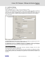
2.2.2.1 Creating a new project and target selection
After having started »PLC Designer« choose => File | New
In the Target Settings dialog select the desired target system.
Then in tab General activate option Support CANopen configuration. If this option is not available in
the dialog and no CAN Master can be inserted in the PLC Configuration, this means that the target
does not support CANopen.
2.2.2.2 Create the PLC application
After having closed the target settings dialog by OK, »PLC Designer« automatically opens a dialog for
adding the main POU PLC_PRG. After having selected the programming language (ST, LD, FBD…)
and closed the dialog with OK you can start programming an application.
2.2.2.3 Including the required libraries
The needed libraries 3S_CanOpenManager.LIB and 3S_CANDRV.LIB and one or several of the
libraries 3S_CanOpenNetVar/Master/Device.lib must be included in the project. For this purpose use
command Window | Library Manager and then for each of the libraries Insert | Additional Library…
from the context menu of the library manager or from the menu bar.
Note:
When you insert one of the libraries 3S_CanOpenNetVar/Master/Device.lib, all libraries referenced by
this library will be included automatically.
Including the libraries is an important step. By the presence of the libraries »PLC Designer« can
recognize that a CANopen project is done, for which then special implicit program parts will be created
automatically.
A description on the »PLC Designer« CAN configurator you find in the »PLC Designer« online help.
See there how to configure a CANopen-Master and slaves.
After having included the CANopen libraries in the project, you must insert a CANopen-Master or Device before you can compile the project without any errors.
DMS 2.0 EN 05/2009 TD29
7
L-force | PLC Designer - CANopen for Runtime Systems
CANopen-Master library
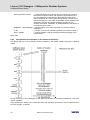
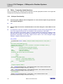
2.2.2.4 Time-controlled PDO transmission for Logic CAN
For the time-controlled transmission of PDOs at the CANopen Logic bus basically the assignment of a
task with the corresponding cycle time is required.
1. For the "UpdateTask", specify the task with the corresponding cycle time by double-clicking in the
"Value" field.
2. Set the transmission type "Cyclic - synchronous" and specify the sync at which the PDOs are to
be transmitted.
The settings of the event time via the "PDO characteristics - ..." dialog are not evaluated.
8
DMS 2.0 EN 05/2009 TD29
L-force | PLC Designer - CANopen for Runtime Systems
CANopen-Master library
2.3
2.3.1
Functionality of the libraries at runtime
Implicit services of the CANopen-Master library
The CANopenMaster library provides implicit services for the »PLC Designer« application that are
sufficient for most of the implementations. These services are integrated transparently to the user and
are available within the application without the need of explicit calls.
Among those services there are the following:
• Reset of all configured slaves at system’s startup
In order to reset the slaves, per default the NMT command ”Reset Remote Node“ is
used, explicitly and singly for each slave. (As per CANopen NMT Network
Management. The particular commands are described in document DSP301.) The
experience of some users has shown that it is reasonable to reset the slaves with a
‚Reset All Remote Nodes’ command, in order not to overstress the receive capacities
of lower-performing slave controllers. This is possible by setting the appropriate flag in
the application program.
Standard
• Polling the slave device type via SDO (Requesting object 0x1000) and
comparing it to the configured Slave ID.
Issuing an error state for those slaves that do not fit the configured type. If no device
type has been received at all, the polling will be repeated after 0,5 seconds, except
the slave is marked as “optional” in the configuration.
Standard
• Configuration of all error-free devices via SDO. Each SDO is watched for a
response and will be repeated if the slave does not respond within the watch time.
Standard
• Automatic configuration of slaves via SDOs that send a boot-up message to the
master while the bus is in operating mode.
Standard
• Starting all slaves after having configured them faultlessly, if option “Automatic
startup” has been activated for the CAN-Master. For starting normally the
NMT-command “Start remote node” is used. As is the case with Reset this
command can be replaced by “Start all remote nodes”.
configurable
• Cycling sending of the sync message.
configurable
• Nodeguarding with lifetime-supervision for each slave and producing an error
state for slaves at which the lifetime-supervision failed.
configurable
• Heartbeat of the master to the slaves and watching the heartbeats of the slaves.
configurable
• Receiving of emergency messages for each slave and storing the last received
emergency messages separately for each slave.
Standard
• Receiving of PDO messages and task-consistent data transfer to the process
image of the application.
Standard
• Sending PDO messages after end of the task, depending on the set
„Transmission Type“ des PDOs.
Standard
DMS 2.0 EN 05/2009 TD29
9
L-force | PLC Designer - CANopen for Runtime Systems
CANopen-Master library
2.3.2
Explicit services of the CANopen library
In addition to the implicit services described above, the CANopen library provides the following
functions:
• Indication of the recently received PDOs via a flag which can be removed by the
application.
Standard
• Application-triggered transmission of remote telegrams for receive-PDOs
Standard
• Application-triggered transmission of SDO objects to slaves
Standard
• Application-triggered reset of slaves with subsequent reconfiguration of slaves
Standard
• Specifically still possible: The application can send and directly receive own CAN
messages to/from the bus. (Layer 2)
Standard
2.3.3
Starting the CANopen network
After a project download to the PLC or after a reset of the application the CAN network will be restarted by the master.
The restart always is done with the same sequence of actions:
• All slaves are reset, except they are marked in the configurator as not to be reset. Resetting is
done singly by the NMT-command „Reset Node“ (0x81), always with the NodeID of the slave.
Exception: the application has set flag „bUseResetAllNodes“; in this case the command for
restarting the network is used once with NodeID 0, „Reset All Nodes“.
• All slaves get configured. For this purpose initially object 0x1000 of the slave gets polled. If the
slave responds within the wait time of 0,5 seconds, the next configuration SDO will be sent. If a
slave is marked “optional” and does not respond to the request within the wait time, it will be
marked as “not existent” and no further SDOs will be sent to it. If a slave responds on the request
for object 0x1000 with another type than configured in the lower 16 bits, it will be configured
nonetheless, but marked as wrong type.
• All SDOs (including the polling for object 0x1000) are sent repeatedly until an answer of the slave
is detected within the wait time. The application can watch the boot-up of the particular slaves and
react if necessary. (see below)
• If the master has configured a heartbeat time unequal 0, the generation of the heartbeat will start
immediately after the start of the master PLC.
• After all slaves have received their configuration SDOs, the nodeguarding will be started for those
slaves that have been configured to be guarded.
• If the master has been configured for automatic startup, now each slave will be started individually
by the master. For this purpose the NMT command “Start Remote Node“ (0x1) is used. If the
application sets the flag „bUseStartAllNodes“, the command will be used with NodeId 0 and thus all
slaves will be started with „Start all nodes“.
• At least once all configured Tx-PDOs (for the slaves these are the Rx-PDOs) will be sent. (It is
always on the application to send RTRs for RTR-PDOs. For this purpose a method of the RxPDOs is available.)
10
DMS 2.0 EN 05/2009 TD29
L-force | PLC Designer - CANopen for Runtime Systems
CANopen-Master library
2.4
Working with the CANopen-Master part in the application
There are various cases in which the IEC application must cooperate with the CANopen library.
Among those is the detection of and reaction on an error.
Regard thereby the call sequence, which cannot be influenced by the application programmer. (The
calls and in which tasks they are generated is also described in chapter 2.5‚ Implicit Calls’.)
Here an example for a CAN controller and a Rx/Tx-PDO each:
• CanRead(0); (* Implicitly created call *)
• pCanOpenMaster[0](); (* Implicitly created call *)
• pCanOpenPDO_Rx[0](); (* Implicitly created call *)
• <processing of the application code>
• pCanOpenPDO_Tx[0](); (* Implicitly created call *)
• MgrClearRxBuffer(wCurTask:= 1,wDrvNr := 0, dwFlags := 0, dwPara := 0); (*Implicitly created call
for clearing the receive buffer.*)
2.4.1
Structure of the CANopen-Master
If the libraries 3S_CanOpenMaster/3S_CanOpenManager and 3S_CanDrv.lib are included in a
project, »PLC Designer« implicitly (automatically) will create a Global Variables List and before/after
the application code in certain tasks will add calls of library modules. The Global Variables List is
named „CanOpen implicit Variables“ and will be filled by »PLC Designer« with the appropriate data
from the PLC configuration.
Note: To view the initialization code in ST without going online, »PLC Designer« can be started by the
command line option “/debug”. In this case (besides other useful information) the files
CanOpenInitcode.exp and CanOpenBeforeTask/AfterTask_<Taskname>.exp will be in the compile
directory.
The variables list „CanOpen implicit Variables“ in details:
The constants always indicate the bounds of the array which are declared in this variables list.
VAR_GLOBAL CONSTANT
MAX_CTRLINDEX : INT := <Maximum Index of the CAN controller in the CANopen
configuration; 0, if there is one controller; 1 if there are two
controllers etc.>;
END_VAR
VAR_GLOBAL CONSTANT
USE_CANOPEN_NODES : BOOL :=
<TRUE indicates whether there is at least 1 Slave below
a master>;
MAX_MASTERINDEX : INT :=
<Index in the controller table (in the Global Variables
List of the CANopen-Manager library) the controllers are
assigned to a master and not to a CanDevice. (for
CanDevice see chapter 3) >;
<Size of the CanOpenNodes array>;
MAX_NODEINDEX : INT :=
MAX_SDOINDEX : INT :=
<Size of CanOpenSDOs array>;
MAX_PDOINDEX_RX : INT :=
<Number of RX-PDOs which are available all over all
CANopen-Masters>;
MAX_PDOINDEX_TX : INT :=
<Number of TX-PDOs available all over all CANopenMasters>;
MAX_MASTER_ODENTRY_IDX : INT := <Number of object dictionary entries all over all
CANopen-Masters>;
END_VAR
DMS 2.0 EN 05/2009 TD29
11
L-force | PLC Designer - CANopen for Runtime Systems
CANopen-Master library
The configuration data are stored in the following arrays:
VAR_GLOBAL
pCANopenMaster : ARRAY[0..MAX_MASTERINDEX] OF CanOpenMaster;
pCanOpenNode : ARRAY[0..MAX_NODEINDEX] OF CanOpenNode;
pCanOpenSDO : ARRAY[0..MAX_SDOINDEX] OF CanOpenSDO;
pCanOpenPDO_Rx : ARRAY[0..MAX_PDOINDEX_RX] OF CanOpenPDO_Rx;
pCanOpenPDO_Tx : ARRAY[0..MAX_PDOINDEX_TX] OF CanOpenPDO_Tx;
ODMEntries: ARRAY[0..MAX_MASTER_ODENTRY_IDX] OF CanOpenODEntry;
END_VAR
Thereby the function block member variables are used as follows: (pure internal variables, declared in
the VAR-sections, should not be written by the application; however some of them are of interest for
diagnosis purposes.)
VAR_INPUT
nStatus : INT;
(* Current status of the master. This status has nothing to do with the
states defined according to CANopen. It is an own, internal definition.
*)
bMsgUsed: BOOL;
(* Can be used by the application in order to detect that a new SDOClient request has been processed. Subsequently e.g. the object
dictionary of the master can be inspected for changes or can be reevaluated. (Only valid if the appropriate entries in the »PLC Designer«
*.cfg-file effect that the master has an object dictionary. Otherwise
without any meaning.)*)
nRxIndex : INT;
(* Historically, in order to avoid compile errors in old projects; not
used.*)
wDrvNr : WORD;
(* Needed for the configuration: Number of the CAN controller, given
from the library to the CAN driver in order to inform the driver on which
controller the write and read requests refer to. The application may not
write this parameter.*)
bUseStartAllNodes : BOOL; (* Can be used by the application to determine whether the library
should use command “Start Node”(FALSE) or “Start All Nodes”
(TRUE). The application only once may write this flag, preferably
during the first few cycles after start. Cyclic writing causes that single
slaves will not be restarted after a failure.*)
bAutoStart : BOOL;
(* TRUE set by PLC Designer if the Autostart option of the master
has been set. *)
bUseResetAllNodes : BOOL; (* Analog to bUseStartAllNodes*)
END_VAR
VAR_OUTPUT
bError : BOOL;
END_VAR
(* Historically, not used.*)
VAR (* Konfig *)
sDrvName : STRING(40);
wBaudrate : WORD;
nFirstNodeNr : INT;
(* Historically, not used.*)
(* Baudrate as used in the configuration, entered by PLC Designer.*)
(* Index of the first slave belonging to the current master, entered by
PLC Designer.*)
nLastNodeNr : INT;
(* Index of the last slave belonging to the current master, entered by
PLC Designer.*)
SyncTimer : TON;
(* Timer used for the generation of the sync message.*)
dwCOBID_Sync : DWORD; (* COBID of the sync message as used in the configuration;
entered by PLC Designer.*)
dwHeartbeatTime : DWORD;(* Heartbeat generation time in ms, entered by PLC Designer.*)
nNodeId : WORD;
HeartbeatTimer :TON;
12
(* NodeId of the master as used in the configuration, entered by
PLC Designer.*)
(* Timer which is used by the master for heartbeat generation.*)
DMS 2.0 EN 05/2009 TD29
L-force | PLC Designer - CANopen for Runtime Systems
CANopen-Master library
bSendHeartbeat : BOOL;
byHeartbeatState : BYTE;
(* Internally set and reset by the master whenever a heartbeat
message should be sent and as soon as it has been sent.*)
(* According to the state of the master here the CANopenconforming states 0, 4, 5 or 127 are entered, which are sent with the
heartbeat-message.*)
(* Index of the first MasterOD-entry in array ODMEntries.*)
(* Number of ODMEntries belonging to this master.*)
wODMFirstIdx : WORD;
wODMCount : WORD;
END_VAR
VAR
bReentry: BOOL;
(* Historically, not used.*)
bGefunden : BOOL;
(* Historically, not used.*)
dwCOBID_NMT : DWORD := 16#0000; (* Exclusively used for starting the slaves. Never should
be changed by the application.*)
nIndex : INT;
(* internal auxiliary variable of the master.*)
dwMerker : DWORD;
(* historically, not used. *)
dwSem : DWORD := 16#FFFFFFFF; (*
Intended for locking operations in multi-tasking
operation. Not used because the implicit calls always are executed
by one task only.*)
a: INT;
(* Lifecounter, only counted up in order to make the implicit calls
visible in monitoring mode. Herewith you can check whether the
master is called.*)
bSynchSend : BOOL;
(* Always will get TRUE for the duration of one IEC-cycle, when
the master sends a sync message. The same also happens when
the master receives an externally generated sync message. If the
master itself generates the sync message, the flag will not be set
when receiving an external sync.*)
bErrCodeNot0 : BOOL;
(* Used to delete the error code of the CAN driver for BusOFF
(Errorcode = 1) with an offset of 1 cycle.*)
MsgBuffer: CAN_Message (* Receive buffer of the master. Only used for the SDO server
functionality and for receiving an external sync message.*);
bSDOMsgUsed : BOOL;
(* Always set in case of an access on the object dictionary of the
master.*);
bSDOReadrqActive : BOOL; (* The following variables are used in order to manage the
accesses on the object dictionary of the master.*)
bSDOWriterqActive : BOOL;
bSub0NotFound, bSDOReadrspAbort, bInitiateRspSend, bSDOWriterspAbort,
bInitiateWrReqSend : BOOL;
i, iActiveSegSDORead : INT;
ucModus : BYTE;
dwIdx : DWORD;
wSegSDOReadSendOffs,wSegSDOReadSendLen : WORD;
pActiveSegSDORead:POINTER TO BYTE;
iActiveSegSDOWrite:INT := -1;
pActiveSegSDOWrite:POINTER TO BYTE;
wSegSDOWriteRecvOffs : WORD;
wSegSDOWriteRecvLen : WORD;
dwODEValue : DWORD;
iSDOReadLen, iSDOWriteLen : INT;
byAbortCode : ARRAY[0..3] OF BYTE;
bSwap : BOOL;
(* Here the master indicates whether it is running on an INTEL or a
Motorola-byteorder machine.*)
END_VAR
Thus, in order to set e.g. variable bUseStartAllNodes of the first master, you have to use
pCanOpenMaster[0]. bUseStartAllNodes := TRUE;
DMS 2.0 EN 05/2009 TD29
13
L-force | PLC Designer - CANopen for Runtime Systems
CANopen-Master library
2.4.2
Structure of the CANopen-node (Slave)
The access on the CANopen-nodes is performed via the implicit variable pCanOpenNode created by
the programming system. This variable is an array of function blocks representing the configured
nodes. Thus methods of the nodes, like e.g. ResetNodes, are called as follows:
pCanOpenNode[0].ResetNode();
„0“ is the index of the node, not the NodeId. The NodeId is part of the function block. All instance data
of a node can be accessed reading and (partly) writing. (For this purpose please open the module
interface in the library manager in »PLC Designer«). The components of the function block in detail:
VAR_INPUT
nRxIndex : INT;
nSDOSend : INT;
(* historically, not used.*)
(* Index of the current SDO, which is sent to the node during the
configuration phase.*)
bAutoStart : BOOL;
(* Always set TRUE as soon as the master sets the node to
automatic start. *)
nNewStatus: INT;
(* Status parameter used when action SetNodeStatus is called.*)
bSynchSend: BOOL;
(* Transferred by the master at call of the module in order to
indicate the receiving of an externally generated sync message or
the generation of a sync message by the master. Only used
internally and immediately reset afterwards.*)
dwHeartbeatTime : DWORD; (* Interval in msec, according to which the master guards the
receiving of a heartbeat message of the node. The configurator will
enter the heartbeat time by using 1,5 times of the heartbeat time of
the node.*)
bSendReset: BOOL := TRUE; (* Per default set by the master, except it wants to use
“Reset All Nodes”. In this case the reset is switched off by the
module.*)
END_VAR
VAR (* Konfig *)
wDrvNr : WORD;
(* Number of the CAN controller used by this module.*)
wMasterIdx : WORD;
(* Index of the master, below which the current slave is running.*)
ucNodeNr : BYTE := 1;
(* NodeID of the slave, as used in the configuration.*)
dwNodeIdent : DWORD;
(* Type of the node, which is also saved in object 0x1000 of the
node.*)
dwGuardCOBID : DWORD; (* COBID of the guard telegram; used when sending nodeguard
telegrams to the slave.*)
dwEmergCOBID : DWORD; (*Emergency COBID; used when waiting for emergency telegrams
of the slave.*)
wDiagSegment : WORD;
(* In the future used for storing the diagnosis address.*)
dwDiagOffset: DWORD;
wFirstSDOIndex : WORD;
(* Range of configuration SDOs for this slave within the array of
SDOs; entered by the configurator.*)
wNummOfSDO : WORD;
(* Number of SDOs, generated by the configurator for this slave.*)
wFirstRxPDOIndex : WORD; (* In these and the following three components the PDOs for this
slave will be identified.*)
wNummOfRxPDO: WORD;
wFirstTxPDOIndex: WORD;
wNummOfTxPDO: WORD;
GuardTime : TIME;
(* Nodeguard time as used in the configuration.*)
GuardTimer : TON;
(* Timer for generation of the guard message.*)
LifeTimer : TON;
(* Timer for guarding the slave. If within the guard time not at least
one answer on a nodeguard telegram is received, a guard error
will be issued. The time for the LifeTimer is calculated as follows:
Lifetimefactor * GuardTime + 0,5 * GuardTime *)
bDoInit : BOOL := TRUE;
(* Set to FALSE by the configurator, if option “Do not initialize” is
set.*)
14
DMS 2.0 EN 05/2009 TD29
L-force | PLC Designer - CANopen for Runtime Systems
CANopen-Master library
bOptional :BOOL;
(* Set to TRUE by the configurator, if option “optional device” has
been set. *)
bHeartbeatConsumer: BOOL; (* Not used. Reserved for information purposes.*)
tHeartBeatLifeTime : TON; (* Watch time for the heartbeat messages of a slave. Always
restarted as soon as a heartbeat message coming from the slave
has been received. *)
END_VAR
VAR_OUTPUT
byLastState : BYTE := 0;
(* Last status, as contained in the answer of the node on the last
guard message.*)
nStatus : INT;
(* Current status of the node. This status is the status of a node
within the current library and is not at all concerned with the status
defined by CANopen!:
0: undefined.
1: Node will be reset by the master and re-configured.
Master waits on a bootup-message of the node (or on the
expiry
of the given guard time) and after that switches the
state of the node to status 2.
2: Master waits ca. 300 msecs before requesting object 0x1000.
Then the status is set to 3.
3: Master starts the configuration of the slave with a SDO-readrequest (index 0x1000) to the node. All SDOs generated by the
configurator will be sent to the node in this status. The
generated SDOs are packed in an array of SDOs, where the
node knows its first SDO and the number of its SDOs. (Instance
components „wFirstSDOIndex” and „wNummOfSDO“)
4: If in the configuration of the Master “Auto startup” is activated,
the node will get sent a „Start Node“ and change to status 5.
5: Node receives/sends PDOs, Master also. Normal operation.
97: Optional node has not been detected at start-up.
98: Node has answered on a request for the device type
(object 0x1000) with a different type.
99: LifeTimer is exceeded, Nodeguarding error.*)
The state of a node during the “normal” operation when I/O data
are being exchanged, is 5.
nSDOActiv : INT;
(* Index of the active SDO, managed by the node; -1 means that no
SDO is active *)
EmcyMsg : CAN_Message; (* Last emergency message received from the node.*)
aEmcyMsg : ARRAY[0..7] OF CAN_Message; (* <Here the last 8 emergency messages received
by the node, will be stored. aEmcyMsg[0] contains the most
recently received and thus latest emergency message.*)
sdoConfig : CanOpenSendSDO; (*Instance of the CanManger-Lib function block, used for the
configuration of the node. *)
END_VAR
VAR
nSDOIndex : INT;
bReady : BOOL;
(* Current index of the configuration SDOs.*)
(* Always when an emergency or guard message has been
received, bReady is set TRUE for the duration of one cycle.*)
SDO_TimeOut: TON := ( PT := T#500ms );
dwMerker : DWORD;
(* Lower 16 bits of object 0x1000, as read from the device.*)
nStatusOld : INT;
(* Internal variable, used to detect a status change.*)
bManualStart : BOOL := FALSE; (* Internally used by StartNode for advising the function block to
start the slave.*)
DMS 2.0 EN 05/2009 TD29
15
L-force | PLC Designer - CANopen for Runtime Systems
CANopen-Master library
bDevTypeInvalid : BOOL;
(* TRUE indicates that the device type given back by the node on
the request of object 0x1000, and the device type entered in the
PLC Configuration are not identical. By setting the node status
(which should be 98 if bDevTypeInvalid is TRUE) manually (or by
the IEC program) to 4, the node nevertheless can be activated. The
application cannot write variable nStatus of a node. For this
purpose the method „NodeStart“ or SetNodeStatus(<new state>) of
the nodes must be used.*)
MsgBuffer : CAN_Message; (* Receive buffer of the node. Internally, only used for special
messages.*)
a: INT;
(* Counter, just used for indicating whether the module is called.*)
iPDO : WORD;
(* Internal variable, used for browsing all PDOs belonging to the
current slave.*)
END_VAR
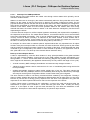
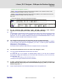
2.4.3
Interpretation and reaction on the states of the library
The phase step-up of the CANopen network initiated by the master passes through the following
states:
During monitoring in »PLC Designer« these states can be seen in the global variables list „Can Open
implicit variables“.
In the following the states of the master and slave are described, so that they can be influenced from
the user program, if required.
16
DMS 2.0 EN 05/2009 TD29
L-force | PLC Designer - CANopen for Runtime Systems
CANopen-Master library
2.4.3.1 Start-up of the CANopen-Master
During start-up of the CAN network the master runs through various states which primarily can be
read from variable nStatus.
States 0, 1 and 2 are run through by the master automatically within the first cycles after a PLC start.
Status 3 of the master is kept for some time. In status 3 the master configures its slaves. For this
purpose the slaves get sent one after the other all SDOs which have been created by the configurator.
After having transmitted all configuration-SDOs to the slaves, the master changes to status 5 and
remains in this status. Status 5 is the normal operation status for the master. After once having
reached this status, the master remains in status 5. All other states are managed by function blocks
representing the slaves.
If a slave does not respond on a SDO request (upload or download), the request will be repeated by
the respective function block. The master leaves status 3, as mentioned above, but not until all SDOs
have been transmitted successfully. Thus it can be detected whether a slave is missing or cannot
correctly receive all SDOs. (Thereby it is irrelevant for the master whether a slave answers with a
confirmation or with an abort, for the master it is only of concern whether any answer has come from
the slave. An example for the detection of aborts during start-up see below.)
An exception is a slave which is marked ‘optional’. Optional slaves are only requested once for object
0x1000. If they do not respond within 0,5 seconds, the slave at this time will be ignored by the master
and the master will change into status 5 without any reaction of the slave. If thenceforwards the slave
is wanted to get re-configured by the master or to be checked for presence, the application must do
that. (See add-on in 2.4.4.2, Boot-up of the network without automatic start.)
Boot-up of the CANopen-Slaves
A slave is represented by a function block instance in array pCanOpenNodes in the global variables
list „Can open implicit Variables“. During boot-up of the CAN network the slave automatically runs
through states -1, 1 and 2. These states mean the following: (Regard: they partially are internal states,
which might be not detected by the application because they are only valid for the length of one cycle.)
• -1 Node is reset by NMT-message „Reset Node“ and autonomously changes to status 1.
• 1 Node changes to status 2 after a maximum time of 2 sec. or immediately after having received its
boot-up message.
• 2 Node automatically changes to status 3 after a delay time of 0,5 sec. This delay matches the
experience that many CANopen devices not immediately after having sent their boot-up message
are ready for receiving their configuration-SDOs. In status 3 the slave gets configured.
The slave remains in status 3 until having received all SDOs created by the configurator. Thereby it
does not matter, whether the slave has responded to SDO transfers with an abort (error) or error-free.
Decisive is just the fact of having got any response from the slave. The application can guard the
responses on the SDO requests and itself can react on the responses of the slaves.
If option „Reset nodes“ is activated in the configurator, a reset of the node will be done after the
transmission of object 0x1011 subindex 1, which after that gets value „load“. Thereby the library
enters „0“ to this object in order to get the reset executed only once after the initialization of the
application. Thereupon the slave will be requested by an upload of object 0x1000.
DMS 2.0 EN 05/2009 TD29
17
L-force | PLC Designer - CANopen for Runtime Systems
CANopen-Master library
After having run through the configuration phase, the slave can change to the following states:
• It always changes to status 4, with the following exceptions: It is an optional slave not detected as
being available at the bus (request object 0x1000). It is available but on the request of object
0x1000 it has responded with a different type in the lower 16 bits than expected by the
configurator.
• It changes to status 97 if it is optional (option „Optional device“ in the CAN configuration) and has
not reacted on the SDO request for object 0x1000.
• It changes to status 98 if the device type (object 0x1000) does not match the configured one, after
nevertheless having got all configuration-SDOs. (Concerning starting the nodes in this case please
see add-on in 2.4.4.2, Boot-up of the network without automatic start.)
If the master is configured for automatic start, the slave will be started in status 4 (i.e. a „Start Node“NMT-messages will be generated) and the slave will automatically change to status 5. Status 5 is the
normal operation mode of the slave. If the master flag bUseStartAllNodes has been set by the
application, then it will be waited until all slaves are in status 4 and after that all slaves will be started
with NMT command „Start All Nodes“.
If the slave is in status 4 or higher, nodeguard messages will be sent to the slave, if nodeguarding is
configured.
2.4.3.2 Nodeguarding / heartbeat errors
In case of a nodeguarding timeout the variable nStatus of the node will be set to 99. In order to restart
the slave it is sufficient to reset the state of the node to 4. Therewith the node gets sent a „Start
communication“ and the CANopen-Master restarts communicating. For this the method „NodeStart“ is
used.
The master autonomously will do this as soon as the node restarts to react on nodeguard requests
and if option „Autostart“ is activated. Thereby the node will be reconfigured or just restarted,
depending on its status, which is contained in the response on the nodeguard requests.
If option Autostart is not activated, the application must call method NodeStart. Depending on the last
saved status (which always is transmitted with the Heartbeat-/nodeguard message), the node will be
restarted or reset.
For heartbeat errors the same proceeding is applicable.
2.4.3.3 Node does not respond in configuration phase
The application can time-guard the configuration phase of a slave and can set nodes, which remain in
status 3, to „TimeOut“. The application can achieve this by calling method „NodeSetTimeoutState“ of
the node (e.g. pCanOpenNode[0]. NodeSetTimeoutState();).
With NodeSetTimeoutState the status of the node will be set to 97. Thus subsequently the node can
be treated like an optional node.
As soon as all configured nodes have reached a status > 4, the master changes to status 5, normal
operation, where an exchange of process data via PDOs is done.
18
DMS 2.0 EN 05/2009 TD29
L-force | PLC Designer - CANopen for Runtime Systems
CANopen-Master library
2.4.3.4 Evaluation of the responses of the slaves on the configuration SDOs
The application can log the complete configuration phase of a node, thus can „see“ each response.
The responses on the configuration SDOs appear in sdoConfig of the node structure: for example in
pCanOpenNode[0].sdoConfig.ucAnswerBytes[0..7] (see also: description of function block
CanOpenSendSDO.)
The master sends one SDO after the other as soon as a response from the slave has been received.
Therefore the application must detect the change of the response in order to determine when a new
SDO response has come in:
VAR
ucOldAnwer : array[0..7] of BYTE;
i : INT;
END_VAR
FOR i := 0 to 7 DO
IF pCanOpenNode[0].sdoConfig.ucAnswerBytes[i] <> ucOldAnswer[i] THEN
ucOldAnswer := pCanOpenNode[0].sdoConfig.ucAnswerBytes;
(* Here the new response can be evaluated, if desired by the application.*)
(* Information on the abort codes see in the description of CanOpenSendSDO.*)
EXIT; (* Leave loop at first change.*)
END_IF
END_FOR
DMS 2.0 EN 05/2009 TD29
19
L-force | PLC Designer - CANopen for Runtime Systems
CANopen-Master library
2.4.4
Examples for application-controlled actions of the libraries
In the following some standard actions are described, which often have to be done by applications.
2.4.4.1 SDO Transfer via function block „CanOpenSendSDO“
In order to control the initiation of a SDO transfer by the application, use module CanOpenSendSDO
of the CanOpenManager library.
Interface of the module:
VAR_INPUT
Enable : BOOL;
wDrvNr : WORD;
(* Rising edge at this flag starts SDO transfer.*)
(* Index of the CAN controller to be used for the SDO transfer. 0 for the
first one, etc.*)
ucNodeId : BYTE;
(* NodeId of the SDO server (receiver of the SDO).*)
wIndex : WORD;
(* Index of the object dictionary entry.*)
bySubIndex : BYTE; (* SubIndex*)
ucModus: BYTE;
(* SDO-mode, 16#40 for read-request,
use 16#23 for 4-byte-write-request.
use 16#27 for 3-byte...
use 16#2B for 2-byte...
use 16#2F for 1-byte...
use 16#21 for a download with more than 4 Bytes.*)
ucByte0 : BYTE;
(* The 4 possible data bytes in the expedited transfer. *)
ucByte1 : BYTE;
ucByte2 : BYTE;
ucByte3 : BYTE;
aAbortCode : ARRAY[0..3] OF BYTE;
(* Additional input parameters in case of a segmented transfer. *)
(* For modes 16#41 and 16#40 for segmented reading and 16#21 for segmented writing. In
these cases a buffer must be defined for the data.*)
dwDataBufferLength : DWORD;
pDataBuffer : POINTER TO BYTE;
END_VAR
VAR_OUTPUT
bWaitForAnswer : BOOL; (* During transmission this flag is set TRUE at least for the
duration of one cycle and after the transmission it is set FALSE.*)
bAnswerRec : BOOL;
(* Only in case of an error-free transmission this flag is set TRUE.*)
ucAnswerBytes : ARRAY[0..7] OF BYTE;
iAnswerLength : INT;
bToggleUnequal: BOOL;
bAbortRec:BOOL;
(* If an there was an abort, this variable will be set TRUE; the abort
code appears in aAbortRec.*)
aAbortRec : ARRAY[0..3] OF BYTE;
END_VAR
VAR
EnableOld : BOOL;
bAnswer : BOOL;
n: INT;
dwActiveCOBId : DWORD;
dwAnswerId : DWORD;
Buffer : CAN_Message;
bExpedited : BOOL;
(* Here the module shows whether the reading has been
done via an expedited or a segmented transfer.*)
bWriteActive : BOOL;
bReadActive : BOOL;
20
DMS 2.0 EN 05/2009 TD29
L-force | PLC Designer - CANopen for Runtime Systems
CANopen-Master library
dwDataOffset : DWORD;
(* After the data transfer the number of actually read
resp. written bytes appears in this variable.*)
dwDataReadLength : DWORD; (* The estimated length of a SDO upload (from the
1. response message).*)
ucUploadRequest: BYTE;
bLastToggle: BOOL;
iCurSDODataLen : INT;
ucDownloadRequest: BYTE;
END_VAR
In order to be able to use this module, for each simultaneous transfer a static instance of the module
must be created (static means: not as a local variable of a function). It is not possible (per CANopen
definition) to open multiple SDO channels to the same slave at the same time.
Send SDO (expedited Mode):
The input parameters to be passed to the module: address (NodeID) of the target node, (0-based)
number of the CAN network on which the module should work, the 4 data bytes, index and subindex
of the target object. Further on the mode in which the module should work must be passed: For
sending of
-
4 Bytes: mode 16#23,
-
3 Bytes: mode 16#27,
-
2 Bytes: mode 16#2B,
-
1 Byte: mode 16#2F.
Example: If a 4-byte value should be written to a SDO server, the call of the module must look like
shown in the following:
sdo(
Enable:= TRUE,
wDrvNr:= 0,
ucNodeId:= 2,
wIndex:= 16#4002,
bySubIndex:= 0,
ucModus:= 16#23,
aAbortCode:=aAbort,
ucByte0 := DWORD_TO_BYTE(dwWrite),
ucByte1 := DWORD_TO_BYTE(SHR(dwWrite,8)),
ucByte2 := DWORD_TO_BYTE(SHR(dwWrite,16)),
ucByte3 := DWORD_TO_BYTE(SHR(dwWrite,24)));
Thereby sdo is an instance of CanOpenSendSDO.
To check whether the transfer has been terminated for example could be programmed like follows::
IF (sdo.bAnswerRec OR NOT sdo.bWaitForAnswer) then
….. (* Transfer is terminated. If bAnswerRec is not TRUE, an error has occurred.*)
END_IF
DMS 2.0 EN 05/2009 TD29
21
L-force | PLC Designer - CANopen for Runtime Systems
CANopen-Master library
Receive SDO:
Like Sending SDO, except that 4 x 0 data Bytes are passed and mode 16#40.
Each other input value for „Mode“ will lead to an undefined behaviour of the module.
Thus the call of the module e.g. could look as follows:
sdo(
Enable:= TRUE,
wDrvNr:= 0,
ucNodeId:= 2,
wIndex:= 16#4001,
bySubIndex:= 0,
ucModus:= 16#40,
aAbortCode:=aAbort);
IF sdo.bAnswerRec AND NOT sdo.bAbortRec THEN
dwRead := SHL(BYTE_TO_DWORD(sdo.ucAnswerBytes[7]),24);
dwRead := dwRead + SHL(BYTE_TO_DWORD(sdo.ucAnswerBytes[6]),16);
dwRead := dwRead + SHL(BYTE_TO_DWORD(sdo.ucAnswerBytes[5]),8);
dwRead := dwRead + BYTE_TO_DWORD(sdo.ucAnswerBytes[4]);
END_IF
It is proceeded on the assumption that in index 4001, Sub0 there is a 4-byte value which always can
be read with an “expedited” transfer.
If it is unknown whether the value is transmitted by the SDO server via expedited transfer or not,
always a data buffer must be defined. In this case, after the transfer has been done, it can be
determined via the flag bExpedited whether the data will appear in ucAnswerBytes[4..7] or in the
buffer.
The input parameter aAbortCode serves to inform the module about the abort code which should be
sent in case the communication is aborted by the application per deleting the enable input. (Always
when a rising edge is detected at the Enable input of the module during a running transfer, an abort
will be generated.)
The module itself does not watch timeouts. Thus the application must watch the SDO transfer and e.g.
via call
Sdo(Enable := FALSE, aAbortCode[0]:=0,aAbortCode[1] := 0,aAbortCode[2] := 4,aAbortCode[3] :=
5);
must pass the abort code „SDO Protocol timed out“. This will be sent at a falling edge at Enable if the
protocol has not yet finished the transfer.
If more than 4 bytes should be read, the address of a buffer and a maximum size of this buffer can be
passed to the module:
sdo(
Enable:= bReadString,
wDrvNr:= 0,
ucNodeId:= 2,
wIndex:= 16#4000,
bySubIndex:= 2,
ucModus:= 16#40,
aAbortCode:=aAbort,
dwDataBufferLength:= SIZEOF(str) ,
pDataBuffer:= ADR(str));
In this example str is a string. The size of this string within the memory can be determined by means
of the SIZEOF operator. The corresponding number of characters will be maximum transferred by the
module. The actually read number of bytes appears after the transfer in dwDataOffset.
22
DMS 2.0 EN 05/2009 TD29
L-force | PLC Designer - CANopen for Runtime Systems
CANopen-Master library
General:
The module always sends the request on COBID: 16#600 + NodeId, the response of the SDO server
always is expected on COBID 16#580 + NodeId.
The response data are transparent, i.e. the response message on the SDO request simply appears in
ucAnswerBytes. This however is only valid for the case of an expedited Read Request (Expedited
Upload). The meaning of the particular bytes is described in the CANopen protocol specification :
-
Byte ucAnswerBytes[0] contains the server command specifier (ssc): 0x60 as a response on a
download request. 0x4y as a response on an upload request (y: Bits 0..3 are allocated as follows:
Bit 1 must be 1, otherwise the SDO server responds with a segmented upload not supported by
the module). 0x80 means that the transfer has been aborted (Abort).
-
Bytes ucAnswerBytes[1..2] contain the index. (Intel-byte-order)
-
Bytes ucAnswerBytes[3] contain the subindex.
-
Bytes ucAnswerBytes[4..7] contain the data of the response, in case of an expedited SDO upload.
In case of an abortion the abort code appears in aAbortRec, see the following table (from
DSP3.01V401):
0503 0000h
Toggle bit not alternated.
0504 0000h
SDO protocol timed out.
0504 0001h
Client/server command specifier not valid or unknown.
0504 0002h
Invalid block size (block mode only).
0504 0003h
Invalid sequence number (block mode only).
0504 0004h
CRC error (block mode only).
0504 0005h
Out of memory.
0601 0000h
Unsupported access to an object.
0601 0001h
Attempt to read a write only object.
0601 0002h
Attempt to write a read only object.
0602 0000h
Object does not exist in the object dictionary.
0604 0041h
Object cannot be mapped to the PDO.
0604 0042h
The number and length of the objects to be mapped would exceed PDO
length.
0604 0043h
General parameter incompatibility reason.
0604 0047h
General internal incompatibility in the device.
0606 0000h
Access failed due to an hardware error.
0607 0010h
Data type does not match, length of service parameter does not match
0607 0012h
Data type does not match, length of service parameter too high
0607 0013h
Data type does not match, length of service parameter too low
0609 0011h
Sub-index does not exist.
0609 0030h
Value range of parameter exceeded (only for write access).
0609 0031h
Value of parameter written too high.
0609 0032h
Value of parameter written too low.
0609 0036h
Maximum value is less than minimum value.
0800 0000h
general error
0800 0020h
Data cannot be transferred or stored to the application.
0800 0021h
Data cannot be transferred or stored to the application because of local
control.
0800 0022h
Data cannot be transferred or stored to the application because of the
present device state.
0800 0023h
Object dictionary dynamic generation fails or no object dictionary is
present (e.g. object dictionary is generated from file and generation fails
because of an file error).
DMS 2.0 EN 05/2009 TD29
23
L-force | PLC Designer - CANopen for Runtime Systems
CANopen-Master library
2.4.4.2 Boot-up of the network without automatic start
Sometimes it is required that the application determines the time at which the CANopen-Slaves should
be started. For this purpose option „Automatic startup“ of the CAN master must be activated in the
configuration. Then the application is responsible for starting the slaves.
The normal way to start a slave via a library is to call the method NodeStart of the respective slave.
This method call after the configuration effects that slaves, for which nodeguarding resp. heartbeat is
activated, will be started depending on their current status, which is contained in their
nodeguard/heartbeat message. If the current status of a slave is not yet „OPERATIONAL“, a „Start
Node“-NMT-command will be sent to the slave.
If the method is used to start a slave which does not use nodeguarding, the slave always will get sent
the complete SDO-set and afterwards a „StartNode“-command will be sent, if the startup was
o.k.(means the device type matched the one in the configuration). In order to start such a slave after
the automatic configuration phase (after which it needs no more configuration SDOs because it just
has received those), it is easier to self-generate a „Start Node“-NMT-command. For this purpose a call
of the CanOpenWriteMSG function block instance can be used (This instance always is available
globally in the manager library.)
CanOpenWriteMSG( wDrvNr := pCanOpenNode[xx].wDrvNr, dwCanID := 0,
ucLen := 2, bRtrFrame := FALSE,
ucByte1 := 16#01, ucByte2 := pCanOpenNode[xx].ucNodeNr);
Thus always one StartNode-NMT-command is put on the bus. The parameters of the module thereby
are read from the array containing the descriptions of the slaves.
IN order to start the complete network, the NMT message also – as described above – can be selfgenerated: (This procedure always must be utilized for nodes which are working without
nodeguarding/heartbeat.)
CanOpenWriteMSG( wDrvNr := pCanOpenMaster[xx].wDrvNr, dwCanID := 0,
ucLen := 2, bRtrFrame := FALSE,
ucByte1 := 16#01, ucByte2 := 0);
This NMT command is named „Start All Nodes“.
Thereby however all node states must be adapted, in order to achieve that the library even sets on the
current state if the master has not started the nodes. So it is better to use the method StartAllNodes of
the master. Then the NMT command “Start All Nodes” will be created and the nodes states will be
updated.
In order to start a slave, which was brought to status 98 during boot-up (device type does not match
with the configured type), it is sufficient to use method SetNodeStatus(nNewStatus := 4). If the master
has been configured to start automatically, the node now will be started. Otherwise the application
must additionally call method NodeStart of the node:
pCanOpenNode[iNodeXX].NodeStart();
If the device type of the node did not fit the one in the configuration, the node has to be started (if
desired) by using the explicit generation of a NMT message, see above. The use of NodeStart will
only lead to a sending of the whole set of configuration SDOs with no Start Node command at the end.
For an optional slave which was not present at the start-up of the master and which therefore currently
is in status 97, the same procedure can be utilized. But also alternatively method NodeReset can be
called. This method always causes that the slave is re-configured and then started. (Indeed it will only
be started if the autostart-option is activated. Otherwise the node nevertheless must be started
manually.)
24
DMS 2.0 EN 05/2009 TD29
L-force | PLC Designer - CANopen for Runtime Systems
CANopen-Master library
2.4.4.3 Stopping a node
By calling method NodeStop, analogue to NodeStart, a NMT-command for stopping the slave will be
created. Thereupon the slave normally will change to status „Stopped“.
2.4.4.4 Resetting a node
By calling method ResetNode the respective slave will be reset and re-configured.
2.4.4.5 Starting the network by bUseStartAllNodes
In a CAN network with many participants (mostly more than 8) it often happens, that NMT-messages
which quickly follow each other are not detected by all (mostly slow) IO-nodes (slaves). This happens
due to the reason that all those nodes must listen to all messages with ID 0. NMT-messages which
are sent in a too quick succession overstress the receive logic of such nodes. A symptom for this fact
is that these nodes sometimes are not started. Relief can only be produced by reducing the number of
quickly succeeding NMT-messages. Additionally the application can cause the CANopenMaster
library to use command “Start All Nodes” instead of starting all nodes singly per „Start Node“.
For this purpose the application must set the flag bUseStartAllNodes of the master uniquely, always
at start of the controller, e.g. like shown in the following (bInit is defined by the application):
IF NOT bInit THEN
pCanOpenMaster[0].bUseStartAllNodes := TRUE;
bInit := TRUE;
END_IF
Attention: This flag may not be set cyclically, because then single nodes after a failure would not be
re-started correctly.
Always when the application uses this command for starting the network, also nodes which – e.g.
because they had responded with a wrong device type – are in status 98, will be started. However,
then PDOs for these nodes remain deactivated. To unlock them the application must act like
described in 2.4.4.2, Boot-up of the network without automatic start. If it is not sure whether all slaves
have been parameterized with the correct device type, member „dwMerker“ of the particular nodes
can be regarded. Here the device type appears, which has been read by the slave via request of
object 0x1000. (In member dwNodeIdent the configured type is stored.) dwMerker is always valid, if it
is unequal 0.
2.4.4.6 Initialization of the network via bUseResetAllNodes
For the same reasons as described for bUseStartAllNodes there are cases in which it is better to use
NMT-command „Reset All Nodes” instead of “Reset Node” for each single node.
For this the application uniquely must set flag bUseResetAllNodes of the master:
IF NOT bInit THEN
pCanOpenMaster[0]. bUseResetAllNodes := TRUE;
bInit := TRUE;
END_IF
Attention: This flag may not be set cyclically because then single nodes would not be re-started
correctly after a failure.
DMS 2.0 EN 05/2009 TD29
25
L-force | PLC Designer - CANopen for Runtime Systems
CANopen-Master library
2.4.4.7 Guarding the configuration phase
The configuration phase of the slaves can be guarded. First of all the master must be guarded in its
boot-up phase, because it will get caught at nStatus = 3, if a non-optional slave is not found during
boot-up.
Slaves, at which a problem occurs during the configuration phase, will get caught at nStatus = 3 or will
directly change to error state > 5 after the configuration phase.
The following examples show application code which can be used to keep working with the CAN
network even in certain situations resp. to get diagnosis information.
During the guarding of the boot-up phase it must be regarded that per IEC-cycle of the task, which
calls the CANopen-Master (also see implicit calls), only one SDO can be transmitted to each slave.
That is, the boot-up phase might take long time, depending on the maximum number of SDOs which
must be transferred to a slave.
2.4.4.7.1 Access on the state of the CANopen-Master
In order to avoid that application code is processed although the IO-network is not yet ready, the
status of the master must be polled:
IF pCanOpenMaster[0].nStatus = 5 THEN
<application code>
END_IF
2.4.4.7.2 Time guarding in the boot-up phase
VAR
Guarding : TON;
iSlave : INT;
bSlaveFound: BOOL;
END_VAR
Guarding(IN:= pCanOpenMaster[0].nStatus < 5, PT := T#10 );
IF Guarding.Q THEN
(* figuring out whether there is a non-configurable slave *)
FOR iSlave := pCanOpenMaster[0]. nFirstNodeNr TO pCanOpenMaster[0]. nLastNodeNr
DO
IF pCanOpenNode[iSlave]. nStatus < 4 THEN
bSlaveFound := TRUE;
EXIT;
END_IF
END_FOR
END_IF
After this sequence in variable iSlave the number (index) of the fist slaves appears, which is still in
status 3 after expiration of the guarding time.
This example only is valid for a non-optional slave. Optional slaves must be managed by the
application, because it is not always recognizable, whether they are available or not. The startup
phase will be validated as “OK” even if optional slaves are not available.
26
DMS 2.0 EN 05/2009 TD29
L-force | PLC Designer - CANopen for Runtime Systems
CANopen-Master library
2.5
Implicit calls
»PLC Designer« creates implicit calls to the CANopen libraries.
If »PLC Designer« is started with command line option /debug, these calls are stored to the compile
directory as files (name starts with CANopen…., extension is “.exp”).
The calls are generated after the following pattern:
If there is no module parameter ‘UpdateTask’ of the CAN master, then all calls will be done in the task
of the highest priority. The CAN-Master and all PDOs belonging to this master will be called in one
task. If parameter UpdateTask of the CAN-Master is set, the task specified there will be used for the
calls.
If PDOs or the master are called according to the above described pattern in an event task, a warning
will be issued.
By adding an entry PDOsToReferenceTasks=TRUE in the CANMASTER section of the target
configuration file (*.cfg) you can achieve the following: The calls of the CAN-Master will be linked to a
task and the PDOs will be created in those tasks in which the IOs of the PDOs are referenced.
Regard: This entry in the cfg-file may not be added without prior consultation of the PLC
manufacturer!
2.6
Object dictionary of the CANopen-Master
In some cases it is helpful if the CAN master has an own object dictionary, e.g. for the data exchange
of the application with other CAN nodes.
The object dictionary of the master is created via an EDS-file during compilation and is pre-allocated
with values.
The EDS-file to be used is defined by two entries in the cfg-file:
MasterEDS=TRUE
MasterEDSFile=MyMaster.eds
In this example the first file named „MyMaster.eds“ which is found all over all configuration directories,
will be used.
The object dictionary is an array of the following structure:
TYPE CanOpenODEntry :
STRUCT
dwIdxSubIdxF : DWORD;
dwContent : DWORD;
wLen : WORD;
byAttrib : BYTE;
byAccess : BYTE;
(* The structure of this component is 16#iiiissff, whereby iiii
signifies 2 bytes index, ss signifies 1 byte subindex and ff
signifies 1 byte flags. *)
(* Content of the entry.*)
(* Data length.*)
(* Originally intended for defining the access right, but can
be arbitrarily used by the master application. *)
(* Formerly access right, but can be arbitrarily used by the
master
application.*)
END_STRUCT
END_TYPE
The »PLC Designer« user interface provides no editor for the object dictionary.
The EDS-file just defines with which objects the object dictionary has to be created. Thereby the
entries always are created with length 4 and the flags (lowest prior byte of the component of an object
dictionary entry dwIdxSubIdxF) always with 16#41 resp. 16#01 for the last entry.
DMS 2.0 EN 05/2009 TD29
27
L-force | PLC Designer - CANopen for Runtime Systems
CANopen-Master library
If an object dictionary is available in the master, the master can act as a SDO server in the network.
Always when a client performs a writing access an object dictionary entry, the application will be
notified through the master flag bMsgUsed. This flag is implemented as an input variable of the master
so that the application can reset the flag. The master only sets the flag.
The application can use the object dictionary by directly writing or reading entries or by the
assignment of entries to IEC variables. In the latter case these IEC variables will be directly accessed
when reading or writing from/to another node.
An entry can be accessed as follows if index/subindex are known:
I := FindInODMEntries(16#iiiiss00, pCanOpenMaster[0].wODMFirstIdx,
pCanOpenMaster[0].wODMFirstIdx + pCanOpenMaster[0]. wODMCount;)
Therewith the index of the entry is available in I.
Now the components of the entry can be accessed directly:
For example: In order to get an entry directly pointing on an IEC variable, it is sufficient to
enter address, length and flags:
ODMEntries[I].dwContent := ADR(<variable name>);
ODMEntries[I].wLen := sizeof(<variable name>);
ODMEntries[I]. dwIdxSubIdxF := ODMEntries[I]. dwIdxSubIdxF OR OD_ENTRYFLG_WRITE
OR OD_ENTRYFLG_ISPOINTER;
In order just to modify the content of the entry it is sufficient to modify dwContent.
Alternatively the following functions can be used, whereby always the index is to be set as input
parameter:
• GetODMEntryDataAddress, for accessing the address of the value of the entry.
• GetODMEntryDataLen, for evaluating the length of the data of the entry.
• GetODMEntryValue, for requesting the value of the entry.
• SetODMEntryValue, for setting the value of the entry.
28
DMS 2.0 EN 05/2009 TD29
L-force | PLC Designer - CANopen for Runtime Systems
CanDevice
3
CanDevice
A »PLC Designer« programmable PLC can appear in a CAN network also as a CANopen-slave (also
named CANopen-node, in the following named „CanDevice”).
3.1
Functionality
The CanDevice library together with the CANopen-configurator provide the following functionality for
the user:
-
Configuration of the following properties in »PLC Designer«: NodeGuarding/Heartbeat,
Emergency, NodeID and baudrate, on which the device should work.
-
Together with the Parameter Manager in »PLC Designer« a default PDO mapping can be created,
which can be modified by the master during run time. The change of the PDO mapping is done
during the configuration phase by the master. By the mapping IEC variables of the application can
be mapped to PDOs.
-
The CanDevice library provides an object dictionary, the size of which is determined by »PLC
Designer« during compilation. This dictionary contains all objects describing the CAN device and
additionally those which are defined by the Parameter Manager. In the Parameter Manager
together with the CanDevice only the list types „Parameters” and “Variables” can be used.
-
The library manages accesses on the object dictionary, thus acting as SDO server at the bus.
-
The library watches the nodeguarding resp. the heartbeat consumer time (only of one producer
each) and sets the corresponding error flags for the application.
-
Creation of an EDS-file, describing the configured properties of the CanDevice in a way that the
device can be configured as slave below a CAN master.
The CanDevice library explicitly not provides the following functionalities which are described in
CANopen. (All possibilities of the CANopen protocol, mentioned here and in the upper paragraph, also
are not implemented) :
-
Dynamic SDO, PDO identifier.
-
Blocking SDO transfer.
-
Implicit generation of emergency messages. Emergency messages always must be created by
the application. For this purpose the library provides a function block, which can be used by the
application.
-
Dynamic changes of the PDO properties resp. runtime properties always are updated at the
arrival of a StartNode NMT-message and at each access on an object in the communication
properties of the CanDevice.
DMS 2.0 EN 05/2009 TD29
29
L-force | PLC Designer - CANopen for Runtime Systems
CanDevice
3.2
Configure CanDevice
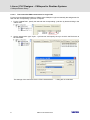
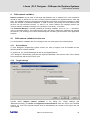
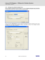
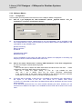
In order to configure a CanDevice, in the context menu of the PLC Configuration choose command
Append subelement -> CanDevice. This command is only available, if at least one .cfg-file
(manufacturer-specific description of the PLC configuration) contains an entry for a CanDevice:
[Module.CanDevice]
Name=CanDevice
Id=78379
DeviceType=CANDEVICE
BasisPrmDlg=FALSE
Class=<class, which can be inserted at the root module of the PLC configuration >
Icon=codsmall.ico (optional)
FixedNumOfPDOs=1 (optional, default mapping is set to 4 PDOs)
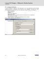
Now you get the following configuration dialog:
30
DMS 2.0 EN 05/2009 TD29
L-force | PLC Designer - CANopen for Runtime Systems
CanDevice
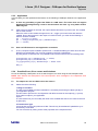
3.3
CanDevice Settings
Bus identifier: currently not used.
Name of updatetask: Name of a task, in which the CanDevice is called.
If from the current settings an EDS-file should be generated, in order to be able to include the
CanDevice in any desired master configuration, activate option Generate EDS-file and enter a file
name. Optionally in addition a template file can be specified, the entries of which will be added to the
EDS-file of the CanDevice. (In case of overlaps the defaults of the template will not be overwritten.)
In tab CAN settings:
Here the Node id and the Baud rate can be set.
The Device Type (default value of object 0x1000, entered in the EDS-file) is predefined with „0x191”
(Standard IO Device) and can be arbitrarily modified by the user.
The Nodeguard parameters, die Heartbeat settings and the Emergency COBID are defined here.
The device here only can be configured for guarding one heartbeat, not for a list of hearbeat
generators. Normally it is sufficient for a slave to guard the heartbeat of its master.
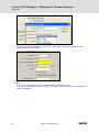
In tab „Default PDO Mapping“:
Here the assignment between local object dictionary (Parameter Manager) and the PDOs
sent/received by the CanDevice is determined.
In the used object dictionary entries (parameter lists of type ‘Variables’) an assignment of object
index/subindex to variables of the application is done. Thereby it must be regarded, that subindex 0 of
an index containing more than one subindices, implicitly will be used to store the number of the
subindices.
DMS 2.0 EN 05/2009 TD29
31
L-force | PLC Designer - CANopen for Runtime Systems
CanDevice
Example:
Purpose: On the first receive-PDO (COB-Id = 512 + NodeId) of the CanDevice variable
PLC_PRG.a should be received.
Thus in the Parameter Manager an index/subindex must be connected with variable
PLC_PRG.a. For this purpose add a line in a variables list and enter index and subindex. In
the access field only „Write Only“ is applicable, because in a receive-PDO only a writeonlyvalue can be mapped. In column “Variable” enter PLC_PRG.a, or press F2 and select this
variable.
Note: The Parameter Manager editor is only available, if in the Target Settings in „Network
functionality“ option „Support parameter manager“ is activated and parameterized with useful
index/subindex ranges.
After that in the ‘Default PDO Mapping’ of the CanDevice the index/subindex entry is assigned
as a mapping entry to a receive-PDO. The properties of the PDO can be defined in the
Properties dialog which is known from the CAN slave configuration below a master.
Only objects of the Parameter Manager, which have got attribute „read-only“ resp. „write-only“, will be
marked as mappable in a possibly generated EDS-file and will appear in the list of mappable
objects.An object which has been created in the Parameter Manager gets assigned a default value in
the EDS-file. This default is either the initial value of the variable (variables lists) or the value defined
by the user (parameter lists).
All other objects will be marked as not mapable in the EDS-file.
32
DMS 2.0 EN 05/2009 TD29
L-force | PLC Designer - CANopen for Runtime Systems
CanDevice
3.4
Generate EDS-file
If an EDS-file should be generated from the configuration of the CanDevice, in order to be able to use
the device in the configuration of a CANopen-Master, it is sufficient to activate the functionality in tab
“Base settings”. Additionally the file name of the file to be generated must be defined. The file will be
generated during the compilation of the project.
Optionally a template for the EDS-file can be specified.
Entries available in the template will not be overwritten by »PLC Designer«. So it is possible to define
parts of the EDS-file, which should not be changed, by a template file.
All the user defined entries in the Parameter Manager get the initial value of a variable (variable list) or
the entered value (parameter list) as the DefaultValue in the EDS file.
In the following see an example showing the content of an EDS-file in detail:
[FileInfo]
FileName=D:\PLC Designer\lib2\plcconf\MyTest.eds
FileVersion=1
FileRevision=1
Description=EDS for PLC Designer-Project: D:\PLC
Designer\CanOpenTestprojects\TestHeartbeatODsettings_Device.pro
CreationTime=13:59
CreationDate=09-07-2005
CreatedBy=PLC Designer
ModificationTime=13:59
ModificationDate=09-07-2005
ModifiedBy=PLC Designer
[DeviceInfo]
VendorName=3S Smart Software Solutions GmbH
ProductName=TestHeartbeatODsettings_Device
ProductNumber=0x33535F44
ProductVersion=1
ProductRevision=1
OrderCode=xxxx.yyyy.zzzz
LMT_ManufacturerName=3S GmbH
LMT_ProductName=3S_Dev
BaudRate_10=1
BaudRate_20=1
BaudRate_50=1
BaudRate_100=1
BaudRate_125=1
BaudRate_250=1
BaudRate_500=1
BaudRate_800=1
BaudRate_1000=1
SimpleBootUpMaster=1
SimpleBootUpSlave=0
ExtendedBootUpMaster=1
ExtendedBootUpSlave=0
[DummyUsage]
Dummy0000=0
Dummy0001=0
Dummy0002=0
Dummy0003=0
Dummy0004=0
Dummy0005=0
Dummy0006=0
Dummy0007=0
DMS 2.0 EN 05/2009 TD29
33
L-force | PLC Designer - CANopen for Runtime Systems
CanDevice
[MandatoryObjects]
SupportedObjects=2
1=1000
2=1001
[1000]
SubNumber=0
ParameterName=Device Type
ObjectType=0x7
DataType=0x7
AccessType=ro
DefaultValue=0x191
PDOMapping=0
[1001]
SubNumber=0
ParameterName=Error Register
ObjectType=0x7
DataType=0x5
AccessType=ro
DefaultValue=
PDOMapping=0
[OptionalObjects]
SupportedObjects=8
1=0x1003
2=0x1005
3=0x100C
4=0x100D
5=0x1014
6=0x1016
7=0x1017
8=0x1018
[ManufacturerObjects]
SupportedObjects=5
1=0x3000
2=0x3001
3=0x3002
4=0x4000
5=0x5000
[1003]
SubNumber=2
ParameterName=Predefined error field
[1003sub0]
ParameterName=Number of entries
ObjectType=0x7
DataType=0x5
AccessType=rw
DefaultValue=1
PDOMapping=0
[1003sub1]
ParameterName=Predefined Error field
ObjectType=0x7
DataType=0x7
AccessType=rw
DefaultValue=0x0
PDOMapping=0
34
DMS 2.0 EN 05/2009 TD29
L-force | PLC Designer - CANopen for Runtime Systems
CanDevice
[1005]
SubNumber=0
ParameterName=COBID Synch Message
ObjectType=0x7
DataType=0x7
AccessType=rw
DefaultValue=0x80
PDOMapping=0
[100C]
SubNumber=0
ParameterName=Guard Time
ObjectType=0x7
DataType=0x6
AccessType=rw
DefaultValue=0
PDOMapping=0
[100D]
SubNumber=0
ParameterName=Lifetime Factor
ObjectType=0x7
DataType=0x5
AccessType=rw
DefaultValue=0
PDOMapping=0
[1014]
SubNumber=0
ParameterName=COBId Emergency
ObjectType=0x7
DataType=0x7
AccessType=rw
DefaultValue=0x80+$NodeId
PDOMapping=0
[1016sub0]
ParameterName=Nums consumer heartbeat time
ObjectType=0x7
DataType=0x5
AccessType=rw
DefaultValue=1
PDOMapping=0
[1016sub1]
ParameterName=Consumer heartbeat time
ObjectType=0x7
DataType=0x7
AccessType=rw
DefaultValue=0x0
PDOMapping=0
[1017]
SubNumber=0
ParameterName=Producer heartbeat time
ObjectType=0x7
DataType=0x6
AccessType=rw
DefaultValue=0
PDOMapping=0
DMS 2.0 EN 05/2009 TD29
35
L-force | PLC Designer - CANopen for Runtime Systems
CanDevice
[1018]
SubNumber=4
ParameterName=Vendor identification
[1018sub0]
ParameterName=Number of entries
ObjectType=0x7
DataType=0x5
AccessType=ro
DefaultValue=2
PDOMapping=0
[1018sub1]
ParameterName=VendorID
ObjectType=0x7
DataType=0x7
AccessType=ro
DefaultValue=0x0
PDOMapping=0
[1018sub2]
ParameterName=Product Code
ObjectType=0x7
DataType=0x7
AccessType=ro
DefaultValue=0x0
PDOMapping=0
For the meaning of the particular objects please see the CANopen specification DS301.
The EDS-file contains, besides the mandatory entries, the definitions for SYNC, Guarding, Emergency
and Heartbeat. If this objects are not used, as Guarding and Heartbeat in the shown example, the
default values are set to 0. But these objects are available at runtime in the object dictionary of the
CanDevice, thus they are described nevertheless in the EDS-file.
Analogue this is valid for the (not listed here) entries for the communication and mapping parameters.
Always all 8 possible (bit mapping is not supported by the library!) subindices of the mapping objects
0x16xx resp. 0x1Axx are available, but potentially not regarded in subindex 0.
Note: With entry FixedNumOfPDOs=1 in the cfg-file in the CANDEVICE section, the mapping objects,
if e.g. no default mapping is predefined, always are set up for 4 PDOs, so that at runtime 4 PDOs are
available for the mapping of variables. Subindex 0 of the mapping objects however is pre-set with 0,
because in case no default mapping is defined none of the objects is allocated.
36
DMS 2.0 EN 05/2009 TD29
L-force | PLC Designer - CANopen for Runtime Systems
CanDevice
3.5
Modifying the default mapping by the master configuration
The given PDO mapping (in the CanDevice configuration) can be modified within certain bounds by
the master.
Thereby the rule must be observed, that CanDevice is not able to create new object dictionary entries,
which are not yet part of the default mapping (Default PDO Mapping in the CanDevice configuration).
So e.g. for a PDO, which contains one object mapped in the Default PDO Mapping, it is not possible
to map a second object in the master configuration.
Thus the mapping modified by the master-configuration maximum can contain the PDOs defined in
the default-mapping. Within these PDOs 8 mapping entries (subindices) are available.
Errors which possibly occur in this context are not indicated bit the redundant PDO definitions /
redundant mapping entries will be treated as non-existent.
The PDOs always must be set up in the master starting with 16#1400 (receive PDO communication
parameters) resp. 16#1800 (send-PDO communication parameters) and must follow each other
without a break.
The default mapping of the CanDevice always is available after a program download. It depends on
the master configuration, whether none-available mappings (not available in the master configuration
but available in the default configuration) will be explicitly overwritten by the master.
DMS 2.0 EN 05/2009 TD29
37
L-force | PLC Designer - CANopen for Runtime Systems
CanDevice
3.6
3.6.1
Working with the CanDevice in the application program
Module CanopenDevice
The module is instanced once for each configured CanDevice. The components of the function block
are used as follows:
bAutoStart : BOOL;
Setting of option “Automatic startup”
ucNodeId : BYTE;
Node-ID of the CanDevice.
wDrvNr : WORD;
Index of the CAN controller in the configuration.
wODStart : WORD;
Index of the first object dictionary entry of the
CanDevice.
wODEnd : WORD;
Index of the last object dictionary entry of the
CanDevice.
wPDOStartRx : WORD;
Index of the first Rx-PDOs of the CanDevice within the
array of RxPDOs (pCanDevPDO_Rx).
wPDOCountRx : WORD;
Number of RxPDOs of the CanDevice.
wPDOCountRxCurMap : WORD;
Running variable for the configuration of the PDO
Mappings of the object dictionary.
wPDOStartTx : WORD;
Index of the first Tx-PDOs of the CanDevice within the
array of TxPDOs (pCanDevPDO_Tx).
wPDOCountTx : WORD;
Number of TxPDOs of the CanDevice.
wPDOCountTxCurMap : WORD;
Running variable for the configuration of the PDO
Mappings of the object dictionary.
ucNodeIdNew : BYTE;
This variable is set by init-code as follows: After calling
the CAN driver function CanInit, in which the driver can
set a new NodeID, e.g. from a rotary switch, this
variable gets assigned the value:
WORD_TO_BYTE(gCanInterface[1].pArray[1]) . Thus
CAN drivers must write a new NodeID in pArray[1].
ErrorCode : WORD;
If the application wants to send an emergency
message, here the input parameter ErrorCode
(according to CANopen) of function block
SEND_EMERGENCY is entered.
ErrorRegister : BYTE;
Like ErrorCode.
ManufacturerErrorField : ARRAY[0..4] OF BYTE;
Analogue to ErrorCode.
bEmergencySent : BOOL;
Always when an emergency message has been sent,
this variable is set TRUE.bClearResetFlags : BOOL;
The application can set this flag to reset the flags that
show the reception of reset-NMT-messages.
bClearODEntryWritten : BOOL;
The application can set this flag to reset the flags that
show write access to the object dictionary.
bInit: BOOL;
Used to detect the first cycle.
bMsgUsed : BOOL;
Internal variable, always set when a device message
was used by the device.
bUseOldBootupToo : BOOL;
Flag, which can be set by the application in the first
cycle in order to cause the device to send also the old
bootup message (emergency with 0 bytes data length).
bGuardError: BOOL;
Set by the library if no guard message has arrived
within a time span of GuardTime * LifeTimeFactor.
ucState: BYTE := 127;
Current status of the device, according to CANopen.
38
DMS 2.0 EN 05/2009 TD29
L-force | PLC Designer - CANopen for Runtime Systems
CanDevice
bHeartbeatError: BOOL;
If the device is configured to be heartbeat consumer,
this flag will be set if no new heartbeat message has
been notified within the configured heartbeat consumer
time.
bResetCommReceived : BOOL;
Reset Communication NMT Message was received. A
flag for the application.
bResetNodeReceived : BOOL;
Reset Node NMT Message was received. A flag for the
application.
bEnterPreOpReceived : BOOL;
Enter Preoperational NMT Message was received. A
flag for the application.
bODEntryWritten: BOOL;
An object dictionary entry was written by SDO-access.
iLastODEntryWritten: INT;
Index of last written entry.
i, iIdx: INT;
Internal running variables.
dwIdx: DWORD;
internal variable for the object dictionary access.
dwIdxHelp : DWORD;
Internal.
bSDOReadrqActive : BOOL := FALSE;
Internal variable for SDO server functionality.
bSDOWriterqActive : BOOL := FALSE;
Internal variable for SDO server functionality.
bSDOReadrspAbort : BOOL := FALSE;
Internal variable for SDO server functionality.
bSDOWriterspAbort : BOOL := FALSE;
Internal variable for SDO server functionality.
ucModus: BYTE;
Internal variable for SDO server functionality.
dwODEValue: DWORD;
Internal variable for SDO server functionality.
bSwap: BOOL;
Internal variable, used to determine whether the
CanDevice is running on a processor using Intel or
Motorola Byteorder. According to CANopen the order of
the bytes in a SDO transfer always is Intel Byteorder.
byAbortCode: ARRAY[0..3] OF BYTE;
Internal variable for SDO server functionality.
iIdxCom: INT;
Internal variable
dwIdCom: DWORD;
Internal variable
dwIdMap: DWORD;
Internal variable
iIdxMap: INT;
Internal variable
iPDOcur: INT;
Internal variable
ucCurPDOLen : BYTE;
Internal variable
iNumOfMappedObjects: INT;
Internal variable
iMapObj: INT;
Internal variable
iCurRxPDO: INT;
Internal variable
iCurTxPDO: INT;
Internal variable
bSendBootUp: BYTE;
Internal variable, always set TRUE when a bootup
message should be sent.
bSendNodeGuard: BOOL;
Internal variable for sending the nodeguard-response.
ucToggle: BYTE;
Toggle-bit of the nodeguard response.
bReentry : BOOL;
Historically
tGuardLifeTime : TON;
Guarding timer for nodeguarding.
bGuardingEnabled : BOOL;
Flag, always set when GuardLifeTime <> 0.
tHeartbeatProducer : TON;
Heartbeatproducer time. According to this time interval
heartbeat messages are created.
tHeartbeatConsumer : TON;
Timer for guarding the arrival of heartbeat messages.
DMS 2.0 EN 05/2009 TD29
39
L-force | PLC Designer - CANopen for Runtime Systems
CanDevice
byHeartbeatConsumerID : BYTE;
ID on which heartbeat messages are expected. Always
only one ID is guarded at a time.
bCurPDOChanged: BOOL;
Internal.
bTransmitCyclic: BOOL;
Internal.
dwSynchCobId : DWORD;
COBId, on which the sync message is expected.
dwSynchWinLen : DWORD;
Configured syncWindowLength.
dwSynComCycle: DWORD;
Configured sync interval.
diHelp : DINT;
Internal.
dwHelp : DWORD;
Internal.
MsgBuffer : CAN_Message;
Buffer for received messages.
a: INT;
Counter, incremented with each cycle in order to get
monitored the number of calls.
dwCobIdPDOMin,dwCobIdPDOMax,dwAcceptance:DWORD; These values are passed to the
driver to enable it to set an acceptance mask.
bInitiateRspSend : BOOL;
Internal.
bInitiateWrReqSend : BOOL;
Internal.
iActiveSegSDORead:INT := -1;
Internal, for the segmented SDO transfer.
pActiveSegSDORead:POINTER TO BYTE;
Internal, for the segmented SDO transfer.
wSegSDOReadSendOffs : WORD;
Internal, for the segmented SDO transfer.
wSegSDOReadSendLen : WORD;
Internal, for the segmented SDO transfer.
iActiveSegSDOWrite:INT := -1;
Internal, for the segmented SDO transfer.
pActiveSegSDOWrite:POINTER TO BYTE;
Internal, for the segmented SDO transfer.
wSegSDOWriteRecvOffs : WORD;
Internal, for the segmented SDO transfer.
wSegSDOWriteRecvLen : WORD;
Internal, for the segmented SDO transfer.
wSwapCheck : WORD := 16#55AA;
Internal, must remain unmodified.
bErrCodeNot0: BOOL;
Check, whether the driver has set a fatal error
(BusOff).
dwEmergCobId : DWORD;
COBId, used for sending emergency messages.
iSDOWriteLen : INT;
Internal.
iSDOReadLen : INT;
Internal.
bGuardingStarted: BOOL;
Set as soon as the first guard message has arrived.
bFirstHeartbeatRecv: BOOL;
Set as soon as the first heartbeat message has
arrived.
bSub0NotFound: BOOL;
Internally used in order to distinguish the abort codes
„Index not found“ and „SubIndex not found“.
40
DMS 2.0 EN 05/2009 TD29
L-force | PLC Designer - CANopen for Runtime Systems
CanDevice
3.6.2
Access on the object dictionary entries by the application program
Naturally there are object dictionary entries which are mapped on variables (Parameter Manager).
But there are also the implicitly generated entries of the CanDevice, which cannot be mapped via the
Parameter Manager in a variable. These entries only appear in array ODentries at runtime. In the
monitoring mode (online mode) of »PLC Designer« all object dictionary entries can be viewed in the
global variables list of 3S_CanOpenDevice.lib.
The access on the content of these objects must, exactly as the accesses on the parameter lists of the
Parameter Manager, be done application-controlled:
Uniquely the index of the entry must be evaluated. For this purpose write (in the following example for
the first CanDevice in the configuration):
Index := FindBinary(16#iiiiss00, CanOpenDev[0].wODStart, CanOpenDev[0].wODEnd);
After that the content of the object can be read via GetODEntryValue(Index).
With SetODEntryValue the content of an object can be manipulated. Alternatively a direct access on
the content is possible, if it is known – like it is always the case for implicit objects – that the basis data
type is a numeric type:
ODEntries[Index].dwContent := xxxxx;
3.6.3
Changing the PDO properties at runtime
If the properties of a PDO should be changed during runtime, this can be done by another node via
SDO write accesses, like described by CANopen. Alternatively a new property can be written directly,
like e.g. the event time of a send-SDO, and subsequently a StartNode-NMT-command can be sent to
a node although this node is started already. This effects that the device will re-interpret the object
dictionary values.
But of course also a local application can change the properties of a PDO.
For this purpose the application just must modify, as described above, the contents of the respective
object(s) and subsequently must call method SetupPDOTable of the CanDevice:
CanOpenDev[0].SetupPDOTable();
DMS 2.0 EN 05/2009 TD29
41
L-force | PLC Designer - CANopen for Runtime Systems
CanDevice
3.6.4
Sending emergency messages by the application program
In order to transmit an emergency message via the application program, function block
SEND_EMERGENCY can be used.
The module has the following interface:
VAR_INPUT
ENABLE : BOOL;
* As long as Enable is TRUE, with each call an emergency message
is transmitted.*)
ErrorCode : WORD; (* Error code; according to CANopen some values are already predefined. (See table below.)*)
ErrorRegister : BYTE; (* The error register is content of object 1001h.*)
ManufacturerErrorField : ARRAY[0..4] OF BYTE; (* Here the application can define its own
error codes.*)
DeviceIndex : INT;
(* The 0-based index of the device, which should send the
emergency messages.*)
END_VAR
VAR_OUTPUT
bReady : BOOL;
END_VAR
(* As soon as the message has been sent, bReady gets FALSE.*)
Table with error codes, from DSP301:
00xx Error Reset or No Error
10xx Generic Error
20xx Current
21xx Current, device input side
22xx Current inside the device
23xx Current, device output side
30xx Voltage
31xx Mains Voltage
32xx Voltage inside the device
33xx Output Voltage
40xx Temperature
41xx Ambient Temperature
42xx Device Temperature
50xx Device Hardware
60xx Device Software
61xx Internal Software
62xx User Software
63xx Data Set
70xx Additional Modules
80xx Monitoring
81xx Communication
8110 CAN Overrun (Objects lost)
8120 CAN in Error Passive Mode
8130 Life Guard Error or Heartbeat Error
8140 recovered from bus off
8150 Transmit COB-ID
82xx Protocol Error
8210 PDO not processed due to length error
8220 PDO length exceeded
90xx External Error
F0xx Additional Functions
FFxx Device specific
42
DMS 2.0 EN 05/2009 TD29
L-force | PLC Designer - CANopen for Runtime Systems
CAN network variables
4
CAN network variables
Network variables can be used to exchange data between one or multiple PLCs. The mechanism
should be easy to handle fort he user. Currently network variables are implemented for CAN and
UDP. The variables’ values are exchanged automatically on the basis of broadcast messages. In UDP
these are realized as broadcast telegrams, in CAN as PDOs. Concerning the used protocol these
services are not-confirmed services, i.e. there is no control whether the message reaches the
receiver. Network variables exchange is a 1 (sender) to n (receiver) - connection.
The Parameter-Manager is another possibility to exchange variables. This is a 1 to 1 – connection,
using a confirmed protocol. This means that the user can guard, whether the message has reached
the receiver. The exchange is not done automatically but via calling function blocks in the application
program.
4.1
CAN network variables for the user
To use the network variables with »PLC Designer« the user must perform the following steps:
4.1.1
Preconditions
A »PLC Designer« programming system Version 2.3 SP5 (or higher) must be installed and the
following libraries must be available:
3s_CanDrv.lib, 3S_CanOpenManager.lib and 3S_CanOpenNetVar.lib
»PLC Designer« automatically generates the required initialization code and the calls of the network
POUs at the start and the end of each cycle.
4.1.2
Target Settings
Activate option Support network variables in the dialog box 'Target Settings' (tab
'Networkfunctionality'). At Names of supported networkinterfaces enter the name of the desired
network, e.g. CAN. The required libraries will then automatically be included in the project with the
next compile.
DMS 2.0 EN 05/2009 TD29
43
L-force | PLC Designer - CANopen for Runtime Systems
CAN network variables
4.1.3
Settings in the Global Variables Lists
Add a new global variables list (command 'Add Object’). The ‘Properties’ dialog will open automatically
(also accessible via command ‘Object Properties…’). Here you define the variables, which you want to
exchange with the other PLCs. Use the to open the following dialog:
Click on the button Add Network to get the options for defining the network properties of the current
variables list. If you have set up several network connections, then you can configure several
connections for each Global variable list.
44
DMS 2.0 EN 05/2009 TD29
L-force | PLC Designer - CANopen for Runtime Systems
CAN network variables
The options and their meaning:
-
Network type: one of the network types which are defined in the Target Settings dialog (tab
'Networkfunctionality').
-
Read: The values of the variables in this list should be read by one or several of the other PLCs in
the network.
-
Write: The values of the variables in this list should be sent to other PLCs. It is recommended to
set only one of the options "Read" or "Write" for a variables list. If some variables of a project
should be read and written, then use two variables lists: one for reading, one for writing. Besides
that it is recommended to have only one PLC in a network which is used to send a certain
variables list.
-
Cyclic Transmission: Only valid, if „Write“ is activated. The values will be sent in the defined
Interval, no matter whether they have changed or not.
-
Transmission at Change: The values will only be sent in case they have changed or when the
time, set at Min. interval, is over.
-
Pack Variables: If this option is activated, as many variables as possible will be packed in one
transmission unit. For UDP a transmission unit has a maximum size of 256 Bytes, for CAN 8
Bytes. If one transmission unit is to small to catch all variables, then further units will be generated.
If the option is deactivated, each variable will be packed in a separate transmission unit. If
‘Transmission at Change’ is activated, for each particular transmission unit it will be checked
whether it has been changed and is to be sent.
-
List identifier (COBID): This is an unique identifier to mark the variables lists which should be
exchanged between several projects. Only lists which have the same identifier can exchange their
data. But assure that the lists, which have the same identifier, also contain identical definitions! For
this it is recommended to use the feature Link to file to export the desired variable list from one
project and to import it into the other projects.
WARNING: In a CAN network the list identifier will be used directly as COBID of the CAN
message(s). There’s no check for collisions of identifiers used here and the ones which are used
in the CANopen-configuration for IO-PDOs.
To exchange data properly between two controllers, the definition of the variable lists in the two
projects must be same. You can use the “Link to file” feature to assure that both projects use the
same variable list. One project should export the file before compile, the other projects import it before
compile.
Besides simple data types, a variable list may also contain structures and arrays. Elements of these
compound data types are sent individually
If a variable list is bigger than the PDO size of the respective network, it is sent using several PDOs.
This means that it can not be assured that all data of a variable list is received in the same cycle.
Portions of the variable list may arrive in different PLC cycles. This can happen also for variables of
array or structure data types.
Options not supported for CAN:
-
Transfer checksum.
-
Answer bootup requests.
-
Confirmed transfer.
-
Request on Bootup.
DMS 2.0 EN 05/2009 TD29
45
L-force | PLC Designer - CANopen for Runtime Systems
CAN network variables
4.1.4
Generated calls
An implicit variable list will be created. For each PDO (sending or receiving) an array entry of type
NetVarPDO_Rx_CAN resp. NetVarPDO_Tx_CAN will be inserted.
For debug purposes a file containing the generated declarations will be created. The file is named
NetworkGlobalVars_CAN.exp and will be found in the compile files directory. (Only if »PLC Designer«
has been started with command line option “/debug”.)
Initialization code is generated, which will initialize the generated data. The initialization code will be
called by the GlobalInit POU, which in turn is called immediately after a download in order to initialize
the project data.
For each task, which uses network variables, initially:
- a receive call will be generated for each PDO.
- a (sole) instance of the POU NetVarManager_Udp_FB bzw. NetVarManager_Can_FB will be called:
NetVarManager_CAN();
At the end for each task, which uses network variables, a send call will be generated for each PDO.
The calls all in all:
CAN_Read(0);
NetVarManager_CAN();
pNetVarPDO_Rx_CAN[0]();
<application code>
MgrClearRxBuffer(wCurTask:= 1,wDrvNr := 0, dwFlags := 0, dwPara := 0);
pNetVarPDO_Tx_CAN[0]();
46
DMS 2.0 EN 05/2009 TD29
L-force | PLC Designer - CANopen for Runtime Systems
Appendix
5
5.1
Appendix
List of SDOs usually created for a slave
The »PLC Designer« CANopen configurator per default creates the following SDOs:
-
Read access on object 0x1000 in order to check the type of the node.
-
Write access on all objects of the EDS-file, which in the current configuration are not matching the
default value defined in the EDS-file and which have got assigned read access in the EDS-file.
-
If in the current configuration „Create all SDOs“ is activated, all communication- and mapping
parameters (1400er, 1600er, 1800er and 1A00er objects) are created each time, the ServiceData
objects (own tab in the configurator) however still only in case of a modification towards the EDSfile.
5.2
Monitoring transmit buffer overruns
In the global varlist of the 3S_CanOpenManager.lib now an array of flags is available for monitoring
transmit buffer overruns to the application:
g_CanMgrTxBufferOverrun[<Controllerindex>].
The application can use these flags for diagnostic and messaging purposes. The flags have to be
reset by the application. The library sets the flags, only.
DMS 2.0 EN 05/2009 TD29
47
L-force | PLC Designer - CANopen for Runtime Systems
Appendix
5.3
FAQs – Frequently Asked Questions
See in the following some frequently asked questions and the appropriate answers. Also regard the
example files and projects provided with the document.
5.3.1
CANopen Functionality
F1:
Concerning the CANopen slave configuration: Is it true, that the object list gets filled via
the Parameter Manager?
A:
Yes
F2:
Can the object list also be created/extended in the »PLC Designer« code? What is to be
done?
A:
The object list for list type „Variables“ can be generated out of the code by using pragmas. (For
how to use pragmas see also the »PLC Designer« user manual resp. online help).
See in the following an example, where in a global variables list Pragmas are inserted, which
will effect that the respective variables will be entered in a list in the Parameter Manager. (The
appropriate configuration of the index ranges must be done in the »PLC Designer« target
settings in category „Networkfunctionality “).
VAR_GLOBAL
g_byCANNodeID : BYTE := 16#10; (* CANopen NodeID normally read from a rotary switch. *)
(*
Format of the ParameterManager entry:
{parameter list=<name> [ name= index=16 subindex= accesslevel= accessright= value= ] }
Possible keys and its values:
name
: The name is only for information purposes
(not shown in PLC configuration or EDS file).
index
: Index of the variable.
subindex
: SubIndex of the variable.
accesslevel : Not used for CAN, but must be defined.
- low :
- middle :
- high :
accessright : Accessright values:
- "read only" : Tx PDO (Input, Master's view)
- "write only" : Rx PDO (Output, Master's view)
value
: Default value.
*)
(* Objects mapped by default *)
wIn : WORD {parameter list=IOs [name=ReadInput16Bit index=16#6100 subindex=16#0
accesslevel=middle accessright="read only" value=0 ] };
wOut : WORD {parameter list=IOs [name=WriteOutput16Bit index=16#6300 subindex=16#0
accesslevel=middle accessright="write only" value=0 ] };
(* Not mappable *)
byMode : BYTE {parameter list=IOs [name=Mode index=16#6500 subindex=16#0
accesslevel=middle accessright="read-write" value=0 ] };
48
DMS 2.0 EN 05/2009 TD29
L-force | PLC Designer - CANopen for Runtime Systems
Appendix
(* Objects could be mapped, if required. *)
wInExt : WORD {parameter list=ExtIOs [name=ReadInput16BitExt index=16#6200 subindex=16#0
accesslevel=middle accessright="read only" value=0 ] };
wOutExt : WORD {parameter list=ExtIOs [name=WriteOutput16BitExt index=16#6400 subindex=16#0
accesslevel=middle accessright="write only" value=0 ] };
END_VAR
-> Lists automatically created in the Parameter Manager:
F3:
A:
Do the following NMT commands work?: Boot-Up, Switching mode between
‘Operational’ and ‘Preoperational’, Reset, Emergency, Node-Guarding?
Yes.
If a ResetNode or ResetCommunication is received, the values of the objects normally are reset
to their default values. In case of a CanDevice this must be done by the application. The
application can use the variables bResetCommReceived and bResetNodeReceived to record,
whether one of the both NMT services has been received.
F4:
A:
Can I modify Guard-Time and Life-Time-Faktor also via my object dictionary?
Yes. If written via an SDO access, the library automatically will modify the respective variables.
If you are writing to the OD from the application, you must - in order to get the modification
effective at all - call the following:
CanOpenDev[0].SetupPDOTable();
This method of the CanDevice effects that the complete OD will be re-interpreted.
F5:
Can Node ID and Baudrate also be set via the »PLC Designer« code?
A:
If you set variable nNewNodeId and afterwards call method
Init();
the device will get a new NodeID. All NodeID-related values in the OD will be adapted.
If you want to modify the baudrated, you must enter that in structure g_CanInterface[xx]
and afterwards call
Can_Init(xx,ADR(g_CanInterface[xx]));
Thereby the driver gets informed about the modification.
F6:
In dialog „Networkfunctionality“ in the Target Settings the size of the object dictionary is
defined. Does this setting only refer to the self-defined range (e.g. 2000...) or also to the
default range (1000...)?
A:
Only the objects defined in the Parameter Manager have to be regarded here.
DMS 2.0 EN 05/2009 TD29
49
L-force | PLC Designer - CANopen for Runtime Systems
Appendix
F7:
My customer specific object dictionary starts at 2000 and ranges to the default I/O-range
(6400). Will this size be a problem?
A:
No, as long as the used controller has enough memory for those variables. If you are using a
target system with a C16x-controller (65K segment limit) then a variable only can have a size of
64K. ODEntries is an array of structures, each needs 12 Bytes. Thus theoretically maximum
65536 / 12 = 5461 entries can be created. But due to the fact that on a C16x system the
module, which initializes all variables at once, also cannot be bigger than 64K, the number of
entries is considerably lower, about 500 to 1000, strongly depending on the rest of the
application.
F8:
As from index 4000,0 I need 130 entries of strings of each 32 characters. Will this be a
problem? How do I get the strings into the object dictionary?
A:
This is to be done like for all other variables. The strings must be IEC variables, then you can
enter them like numeric variables via the Parameter-Manager and can access them via SDO
transfers.
F9:
Can you write from „outside“ (i.e. from the master) to „my“ mapping table (i.e. in my
object dictionary)?
A:
see chap. 3.5 Modifying the default mapping by the master configuration
The given PDO-Mapping (in the CanDevice configuration) can be modified by the master within
certain confines. The rule ist hat the CanDevice is not able to create new object dictionary
entries, which are not yet available in the standard mapping (Default PDO-Mapping in ther
CanDevice configuration). Thus e.g. for a PDO, which contains a mapped object in the default
PDO mapping, no second object can be mapped in the master configuration..
So the mapping modified in the master configuration at maximum can contain those PDOs
which are available in the standard mapping. Within those PDOs there are 8 mapping entries
(subindices).
Possible errors which might occur in this context, will not be indicated, but the redundant PDO
definitions / redundant mapping entries will be treated as if they were not existing.
In the master the PDOs always must be arranged starting at 16#1400 (Receiving-PDO
communication parameter) resp. 16#1800 (Sending-PDO communication parameter) and must
gaplessly follow each other.
The standard mapping of the CanDevice always is available after having loaded the program. It
depends on the master configuration, whether non-available mappings (available in the master
configuration, but not available in the standard configuration) will explicitly be overwritten by the
master.
F10; How many PDOs are allowed?
A:
50
There is only a limit given by the memory space, but no systematic limit.
DMS 2.0 EN 05/2009 TD29
L-force | PLC Designer - CANopen for Runtime Systems
Appendix
F11: I must write device specific data to index 1000,1008,1009,100A. How can I do this?
A:
see chap. 3.6.2 Access on the object dictionary entries by the application program
Naturally there are object dictionary entries (OD entries), which are mapped on variables
(Parameter-Manager).
But there are also the implicitly generated entries of the CanDevice, which cannot be mapped to
a variable via the Parameter-Manager. These entries are only visible at run time of the system
in array ODEntries. In monitoring mode (online mode) of »PLC Designer« all object dictionary
entries can be seen in the global variable list of the 3s_CanOpenDevice.lib.
The access on contents of these objects – like the access on parameter lists of the ParameterManager - must be controlled by the application.:
One-time the index of the entry must be evaluated. For this purpose write (see here for the first
CanDevice within the configuration):
Index
:=
FindBinary(16#iiiiss00,
CanOpenDev[0].wODStart,
CanOpenDev[0].wODEnd);
After that the content of the object can be read with GetODEntryValue(Index).
With SetODEntryValue the content of an object can be manipulated. Alternatively the content
can be directly accessed, if – which is always the case for implicit objects – you know that it is a
numeric base data type.:
ODEntries[Index].dwContent := xxxxx;
F12: If one writes from outside to my object dictionary, I can only recognize this by the
change of the variable which is assigned to the respective index/subindex. Is it also
possible in the »PLC Designer« code to directly receive incoming write accesses on my
object dictionary (via »PLC Designer« instruction)?
A:
see chapter 3.6.1: Description of the module CANopenDevice: Variable bODEntryWritten
und iLastODEntryWritten.
F13: Only read-only and write-only objects can be managed. However in my application I need
to use also read-write objects. I wonder if there is already an update solving this
problem?
A:
Read-Write objects are viewed in the master configuration dialog in tab Service Data Objects (> ErrorModeOutput16Bit). They also can be modified there. If these values get modified
(deviation from the default value) the object will be sent to the CANdevice during startup phase.
However it is not possible to map these objects to PDOs. According to CANopen norm mapable
objects always are either read-only or write-only.
F14: I do not want to have the boot-up message acc. V4; I need the V3-variant.
A:
You can use a V3 bootup message additionally to the other one. Both will be sent when you set
variable
bUseOldBootupToo := TRUE; in the first PLC cycle.
DMS 2.0 EN 05/2009 TD29
51
L-force | PLC Designer - CANopen for Runtime Systems
Appendix
5.3.2 CANopen Master
5.3.2.1 Configuration
In this chapter you find questions and answers on the CANopen-Master configuration.
F1:
How do I get displayed the CAN Parameters options „Optional device“ and „No
initialization“ in the PLC Configuration dialog?
A:
The CAN Parameters options „Optional device“ and „No initialization“ can be activated via the
PLC configuration file (*.cfg). For this purpose you have to add the entries „OptionalDevice“ and
„NoInitialize” for the CANopen slave.
[Module.CanSlave]
Name=CanSlave
Id=693734
…
OptionalDevice=TRUE
NoInitialize=TRUE
Just the availability of the entries will effect that the options are displayed in the dialog. By
assigning FALSE or TRUE the default value can be set.
F2:
How to use option "Reset node" in dialog "CAN Parameters" of the PLC configuration?
The tick of this option is deactivated and greyed.
Questions:
before
- Can I use this option to define that "NMT Reset Node" should be send to the node
configuration (otherwise "NMT Reset Communication" ) ?
- How can I modify the option setting, i.e. how do I get editable the tick?
- How can I set a default value fort his option (activated, deactivated)?
- Is the current value of the option setting available in the download structure (structure
CCCanSlave in RTSCFG.H does not contain an appropriated entry)
A:
This option will be activated, if object 0x1011 is available in the EDS-file, resp. deactivated, if
this object is not listed in the file. You cannot set a default value there.
If SDOWrite is executed on this object, the default values will be stored back and ResetNode
will be executed.
In the download structure there is no direct variable indicating this value. However you can
check the list of SDOs for the object: If it is available the word “load” will be written in the 32-bitvalue.
52
DMS 2.0 EN 05/2009 TD29
L-force | PLC Designer - CANopen for Runtime Systems
Appendix
5.3.3
Application
In this chapter you find questions and answers on the handling of CANopen libraries in the application
layer.
F1:
Is there any possibility to guard the PDOs of a CAN slave? The slave does not support
Heartbeat and Nodeguarding. I want to check whether the slave e.g. every 50ms sends a
PDO telegram.
A:
Always when a RxPDO is received, the output variable bNewMessage will be set. The variable
has no other function.
When the value of this variable changes from 0 to 1, trigger your watch timer and reset the
variable. Due to the fact that it is the output of a function block, you must do the following in
order to reset the variable:
pB : Pointer TO BOOL;
pB := ADR(pCanOpenPDO_Rx[0].bNewMessage);
pB^ := FALSE;
F2:
How can RTR frames be sent application-controlled?
A:
In the „CanOpen implicit Variables“ (Ressources -> Global Variables) you find a list of all CAN
RxPDOs (pCanOpenPDO_Rx) currently mapped in the PLC Configuration.
By using action SendRTRFrame it is possible to send a RTR frame to the corresonding PDO.
pCanOpenPDO_Rx[x].bNewMessage := FALSE;
pCanOpenPDO_Rx[x].SendRTRFrame;
If pCanOpenPDO_Rx[x].bNewMessage = FALSE Then
...
END_IF
5.3.4
Possible Errors, Error causes and Solutions
Find in the following a description on errors which might occur when using the 3S-CANopen-stack.
NOTE: Also observe the descriptions of the drive-specific error messages in the respective drive
documentations.
F1:
The outputs are not set. What can be the reason?
A:
Please check the following:
1.Usage of variables
In order to get updated the output variables it is necessary that those get called cyclically in
your application program.
For this reason open the PLC Configuration and define a name for the output (e.g.: byOut1).
Then call this output in your application.
byOut1;
In online mode now you can modify the value of the variable and write to new value to the PLC
by [Ctrl]+[F7].
2.Transmission Type
It may be that you have asynchronous PDO. This will only be transferred if parallel the syncfunctionality is activated.
You can check this by having a look at the properties of the respective PDO.
DMS 2.0 EN 05/2009 TD29
53
L-force | PLC Designer - CANopen for Runtime Systems
Appendix
If the PDO should be transferred synchronously, additionally the sync-functionality must be
activated (yellow marked fields).
Hint:
For the Com. Cycle Period enter an integer multiple of the task cycle time.
If you e.g. have set a task cycle time of 10ms, it is recommended to set a Com. Cycle Period of
10000 µs, 20000 µs, …
54
DMS 2.0 EN 05/2009 TD29
© 05/2009
)
Lenze Automation GmbH
Grünstraße 36
D-40667 Meerbusch
Germany
Service
Lenze Service GmbH
Breslauer Straße 3
D-32699 Extertal
Germany
+49 (0)21 32 / 99 04-0
00 80 00 / 24 4 68 77 (24 h helpline)
¬
+49 (0)21 32 / 7 21 90
¬
+49 (0)51 54 / 82-11 12
|
[email protected]
|
[email protected]
Þ
www.Lenze.com
SHPPLCDCAN 13296252 EN 2.0 TD29
10
9
8
7
6
5
4
3
2
1