1
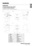
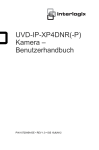
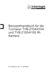
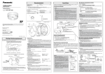
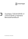
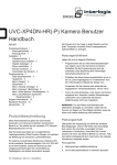
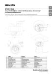
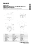
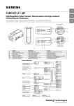
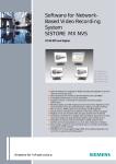
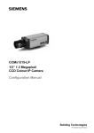
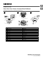
EN
CFMC1315-LP
DE
Indoor Dome Colour Camera / Innenraum-Dome-Farbkamera
Installation Instruction / Installationsanleitung
Black
Brown
Red
8
Orange
Red+
Black-
COM
Alarm Out
1
GND
Alarm In
2
Power In
3
4
Black Audio Out
White Audio In
14
15
SD CARD
DEFAULT
10
SIEMENS
21
P
16
5
13
6
9
12
7
22
19
17
11
20
18
23
1
2
3
4
5
6
7
8
9
10
11
12
13
14
15
16
17
18
19
20
21
22
English
Alarm out terminal
Alarm in terminal
Power IN connector
Audio out (φ3.5mm)
Audio in (φ3.5mm)
Body casing
SD Card slot
Default button
Microphone
Front cover screw
Dome cover
Pan adjustment bracket
Tilt adjust screws
Horizontal adjustment ring
Zoom lever
Focus lever
Reset button
Bottom casing
MON (Monitor out connector)
IP/TV selection
Loosen the locking screw
Open/close dome indication
Deutsch
Alarmausgang
Alarmeingang
Stromversorgungsanschluss
Audioausgang (φ 3,5 mm)
Audioeingang (φ 3,5 mm)
Gehäuse
SD-Kartensteckplatz
Standardvorgaben
Mikrofon
Frontblendenschraube
Dome-Abdeckung
Schwenk-Einstellvorrichtung
Neige-Einstellschrauben
Horizontaler Justierring
Zoomhebel
Fokushebel
Reset-Taste
Gehäuseunterteil
MON (Monitorausgang)
IP/TV-Auswahl
Lösen der Fixierschraube
Dome-öffnen/schließen-Anzeige
Building Technologies
Fire Safety & Security Products
1/3” 1.3 MP IP Indoor Dome Colour Camera
Package contents
Step 3: IP/TV selection
•
•
•
•
The video out signal can be switched either by composite
output or Ethernet mode. It is based on end user selection. If
you switch IP mode, video signal is through Ethernet.
However, you switch TV mode, video out is directly
connected BNC connector.
•
•
•
•
•
CCD IP dome
Documentation CD
Utilities CD
Installation instruction (English, German, French,
Spanish, Italian)
SD card (2GB)
Wall plugs (4x)
Mounting screw (4x)
Mounting template for installation
Monitor out cable *1
•
•
•
•
This quick start guide is only intended for use by
installers who have an adequate working knowledge of
video systems!
This guide outlines the most important information about
the camera. It is, however, vital that you also refer to the
full operating instructions on CD.
Do not touch the housing while the camera is in
operation.
Ensure that the IP camera is installed and operated
under conditions of adequate heat discharge.
Do not install the camera in an outdoor housing.
Ordering Data
Type
CFMC1315-LP
1.
2.
3.
Safety
•
Adjusting the camera
Item Number
S54561-C81-A1
Description
1/3” 1.3 MP Indoor IP
Dome Colour Camera
12 V DC / 24 V AC,
50 Hz or PoE
4.
5.
6.
Setting camera parameters
Camera parameters can be modified through the IP
connection. You can follow the user manual of CFMC1315LP for the IP function and parameter setting.
IP connection
Connect the Ethernet connector with an RJ45 cable, then
follow the user manual of CFMC1315-LP for the IP function. If
direct connection to a PC network card is required, a crossover LAN cable should be used.
General guidelines
Operation and storage
1.
Do not operate or store the unit in the following locations:
• Extremely hot or cold places
• Close to sources of strong magnetism
• Close to sources of powerful electromagnetic radiation
such as radios or TV transmitters.
• In humid or excessively dusty places
• Where exposed to mechanical vibrations.
• Close to fluorescent lamps or objects reflecting light.
• Under unstable or flickering light sources
4.
5.
6.
Caution
Do not turn the lens more than 360° as this may cause
internal cables to disconnect or break.
7.
8.
Align the notch with position “P”. Rotate the cover
clockwise to lock the cover to the base. Tighten the
locking screw (see Fig. C).
To turn the power on, insert the plug of the power cord
into a power outlet. Turn the power on after you have
installed the camera.
Care and maintenance
The camera is maintenance-free. Small amounts of dirt or
dust can be cleaned from the camera body using a clean soft
cloth.
For the latest camera firmware update, please
refer to the following download link:
http://www.siemens.com/cctv
Specifications
Step 2: Connecting the cables
Image sensor
1.
Effective pixels
Image compression
method
Image frame rate
2.
3.
Connect the control input to the terminals GND and AL IN
(2).
For configuration and operation of the camera via
Ethernet, connect the IP cable to the RJ45 connector.
Connect the power supply cable to the power connectors
(3) (Fig. A):
Caution
If using a DC supply, make sure the polarity is correct.
Incorrect connection may cause malfunction and/or damage
to the camera.
Min. Illumination
Synchronisation
Network connection
Internet protocol
Select one of the following options
For 12 V DC:
• Connect 12 V (-) to terminal = DC12V• Connect 12 V (+) to terminal = DC12V+
For 24 V AC:
• Connect 24 V (~) cables to terminals ~AC24V
(13 and 14).
PoE:
• Connect the network cable to the RJ45 terminal using a
hub or a switch.
Electrical and electronic products should be
disposed of separately from the municipal
waste stream via designated collection facilities
appointed by the government or the local
authorities.
Caution
Retighten the locking screws to prevent loss of adjustment.
Step 1: Mounting the camera
2.
3.
EN
Loosen the zoom lever/locking screw (15) by turning it
counter-clockwise.
Rotate the zoom ring to achieve the desired picture.
Loosen the focus lever/locking screw (16) by turning it
counter-clockwise.
Rotate the focus ring to adjust the focus.
If readjustment is necessary, repeat the steps above.
Retighten the zoom lever/locking screw (15) and the
focus lever/locking screw (16).
Installing the camera
Make a hole in the ceiling/wall where the camera is to be
installed to insert the power cable, LAN cable and other
cables.
Drill the holes for the mounting screws.
Feed the power cable, LAN cable and other cables
through the hole (see Fig. A).
Loosen the locking screw. To remove the cover, rotate
the cover counter-clockwise (see Fig. C).
Mount the camera to the ceiling/wall.
Adjust the viewing angle (12, 13 and 14) (see Fig. B).
Disposal
Power requirement
Camera weight
Operating
temperature
1/3” progressive ExviewHAD CCD,
1.3 Megapixels
1280 (H) x 960 (V)
Motion JPEG/ MPEG4
Quad VGA (12.5fps max.)
VGA 640 x 480,
QVGA 320 x 240 (25 fps max.)
Colour 0.4 lx (F1.2, AGC ON)
Internal
RJ45 1 x10/100 based-T Ethernet
connection for LAN/WAN
TCP/IP, UDP, HTTP, SMTP, DNS,
DHCP, NTP, ARP, ICMP, DDNS,
FTPc, FTPs, DHCPc, RTSP,
RTCP, RTP, IGMPv3
12 V DC / 24 V AC, 50 Hz or PoE
0.65 kg (camera only)
-10 to +50 °C
2
Siemens Building Technologies
Fire Safety & Security Products
01.2009
1/3 Zoll 1.3 MP Innenraum-Dome-Farb-IP-Kamera
Lieferumfang
Schritt 3: IP/TV-Auswahl
•
•
•
•
Das Videoausgangssignal kann entweder via CompositeAusgang oder Ethernet-Modus geschaltet werden; dies hängt
von der Auswahl durch den Endbenutzer ab. Im IP-Modus
wird das Videosignal via Ethernet geschaltet. Beim
Umschalten in den TV-Modus hingegen erfolgt die
Videoausgabe direkt über den BNC-Anschluss.
•
•
•
•
•
CCD IP-Dome
Dokumentations-CD
Software-CD
Installationsanleitung (Englisch, Deutsch, Französisch,
Spanisch Italienisch)
SD-Karte (2 GB)
Dübel (4x)
Befestigungsschrauben (4x)
Montageschablone für Installation
Monitorausgangskabel *1
Sicherheit
•
•
•
•
•
Artikelnummer
S54561-C81-A1
Beschreibung
1/3 Zoll 1.3 MP IP
Innenraum-DomeFarb-IP-Kamera
12 V DC / 24 V AC,
50 Hz oder PoE
Kamerainstallation
Schritt 1: Montieren der Kamera
1.
2.
3.
4.
5.
6.
Bereiten Sie an der Stelle in der Wand/Decke, an der die
Kamera angebracht werden soll, eine Öffnung für das
Stromversorgungskabel, das LAN-Kabel und sonstige
Kabel vor.
Bohren Sie die Löcher für die Befestigungsschrauben.
Führen Sie das Stromkabel, das LAN-Kabel und die
sonstigen Kabel in die Öffnung ein (siehe Abb. A).
Lösen Sie die Fixierschraube Drehen Sie die Abdeckung
gegen den Uhrzeigersinn, um sie zu entfernen (siehe
Abb. C).
Befestigen Sie die Kamera an der Decke/Wand.
Stellen Sie den Sichtwinkel (12, 13 und 14) ein (siehe
Abb. B).
Vorsicht
Drehen Sie das Objektiv nicht um mehr als 360°, da sonst die
Kabel im Inneren abgetrennt oder beschädigt werden
könnten.
7.
8.
Richten Sie die Kerbe mit Position "P" aus. Drehen Sie
die Abdeckung im Uhrzeigersinn, um sie am Sockel zu
verriegeln. Ziehen Sie die Fixierschraube fest (siehe
Abb. C).
Um die Stromversorgung herzustellen, schließen Sie den
Stecker des Stromkabels an einer Steckdose an.
Schalten Sie die Stromversorgung ein, nachdem Sie die
Kamera installiert haben.
Schritt 2: Anschließen der Kabel
1.
2.
3.
Elektrische und elektronische Geräte dürfen
nicht im Hausmüll entsorgt werden, sondern
sind an den von den Kommunen dafür
eingerichteten Sammelstellen abzugeben.
1.
3.
4.
5.
6.
Drehen Sie den Zoomhebel/Fixierschraube (15) gegen
den Uhrzeigersinn los.
Drehen Sie am Zoomring, um das gewünschte Bild zu
erhalten.
Drehen Sie den Fokushebel/Fixierschraube (16) gegen
den Uhrzeigersinn los.
Drehen Sie am Fokusring, um die Bildschärfe
einzustellen.
Sollten weitere Justierungen erforderlich sein,
wiederholen Sie die Schritte oben.
Ziehen Sie den Zoomhebel/Sicherungsschraube (15) und
den Fokushebel/Sicherungsschraube (16) wieder fest.
Vorsicht
Ziehen Sie die Sicherungsschrauben nach, damit die
Einstellung erhalten bleibt.
Kameraparameter einstellen
Bestelldaten
Typ
CFMC1315-LP
DE
Kameraeinstellungen
2.
Diese Kurzanleitung ist nur für Fachpersonal
vorgesehen, das mit Videosystemen ausreichend
vertraut ist!
Hier finden Sie schnell die wichtigsten Informationen über
die Kamera. Beachten Sie jedoch unbedingt auch die
ausführliche Betriebsanleitung auf CD.
Berühren Sie nicht das Gehäuse, solange die Kamera in
Betrieb ist.
Achten Sie darauf, die Kamera so zu installieren und zu
betreiben, dass eine ausreichende Wärmeableitung
sichergestellt ist.
Installieren Sie die Kamera nicht in einem Gehäuse für
den Einsatz im Freien.
Entsorgung
Verbinden Sie den Steuereingang mit den Anschlüssen
GND und AL IN (2).
Zur Konfigurierung und Bedienung der Kamera via
Ethernet muss das IP-Kabel mit dem RJ45-Anschluss
verbunden werden.
Schließen Sie das Stromversorgungskabel an den
entsprechenden Anschlüssen (3) an (Abb. A).
Die Kameraparameter können über den IP-Anschluss
konfiguriert werden. Hinweise zur IP-Funktion und den
Parametereinstellungen finden Sie im CFMC1315-LPBenutzerhandbuch.
IP-Anschluss
Schließen Sie ein RJ45-Kabel am Ethernetanschluss (3) an.
Hinweise zur IP-Funktion finden Sie im CFMC1315-LPBenutzerhandbuch. Die Direktanschluss an eine PCNetzwerkkarte ist ein Crossover-LAN-Kabel erforderlich.
Allgemeine Richtlinien
Betrieb und Lagerung
Betreiben oder lagern Sie das Gerät nicht unter folgenden
Bedingungen:
• an extrem heißen oder kalten Orten
• in der Nähe starker Magnetfelder
• im Umfeld starker elektromagnetischer Strahlungsquellen
wie Radios oder Fernsehsender
• an feuchten oder extrem staubigen Orten
• an Orten mit mechanischen Erschütterungen
• in der Nähe von Leuchtstoffröhren oder Licht
reflektierenden Objekten
• unter unbeständigen oder flimmernden Lichtquellen
Pflege und Wartung
Die Kamera ist wartungsfrei. Bei leichter Verschmutzung
kann das Kameragehäuse mit einem weichen Tuch gereinigt
werden.
Informieren Sie sich unter folgendem
Download-Link über die neusten
Aktualisierungen der Kamera-Firmware:
http://www.siemens.com/cctv
Technische Daten
Bildsensor
effektive Bildpunkte
Bildkompressionsverfahren
Bildrate
min. Lichtstärke
Vorsicht
Achten Sie bei Gleichstromversorgung auf die korrekte
Polarität. Anschlussfehler können zu Fehlfunktionen und/oder
Schäden an der Kamera führen.
Synchronisation
Netzwerkanschluss
Wählen Sie eine der folgenden Optionen:
Internetprotokoll
12 V DC:
• Schließen Sie 12 V (-) am Anschluss =DC12V- an.
• Schließen Sie 12 V (+) am Anschluss =DC12V+ an.
24 V AC:
• Schließen Sie 24 V (~)-Kabel an den Anschlüssen
~AC24V (13 und 14) an.
PoE:
• Schließen Sie das Netzwerkkabel über einen Hub oder
Switch am RJ45-Anschluss an.
Stromversorgung:
Gewicht
Betriebstemperatur
1/3 Zoll Progressive
ExviewHAD CCD, 1,3
Megapixel
1280 (H) x 960 (V)
Motion JPEG / MPEG4
Quad VGA bei 12,5 fps max.
VGA 640 x 480,
QVGA 320 x 240 bei 25 fps
max.
Farbe 0,4 lx (F1.2, AGC
EIN)
intern
RJ45 1 x 10/100 Base-T
Ethernet-Anschluss für
LAN/WAN
TCP/IP, UDP, HTTP, SMTP,
DNS, DHCP, NTP, ARP,
ICMP, DDNS, FTPc, FTPs,
DHCPc, RTSP, RTCP, RTP,
IGMPv3
12 V DC / 24 V AC, 50 Hz
oder PoE
0,65 kg (nur Kamera)
-10 bis +50 °C
3
Siemens Building Technologies
Fire Safety & Security Products
01.2009
Issued by
Siemens Building Technologies
Fire & Security Products GmbH & Co. oHG
D-76181 Karlsruhe
www.buildingtechnologies.siemens.com
Document no.
A6V10234978
Edition
13.01.2009
© 2009 Copyright by
Siemens Building Technologies
Data and design subject to change without notice.
Supply subject to availability.