1
For the heating engineer
Installation and maintenance instructions
ecoTEC
Gas fired wall hung high efficiency boiler
GB
VU 656/4
Contents
Contents
1
1.1
1.2
1.3
Notes on the documentation...........................
Storage of documents .............................................
Safety instructions and symbols ...........................
Validity of the instruction manual ........................
2
2.1
2.2
2.3
2.4
2.5
Description of the boiler .................................. 4
Design .......................................................................... 4
Type summary ........................................................... 5
CE label ........................................................................ 5
Intended use ............................................................... 5
Identification plate .................................................... 5
3
3.1
3.1.1
3.1.2
3.1.3
3.2
3.2.1
3.2.2
3.2.3
3.3
3.3.1
3.3.2
3.4
3.5
3.6
Safety instructions and regulations .............. 5
Safety instructions ................................................... 5
Installation and setting ............................................ 5
Gas odour .................................................................... 5
Changes to the surroundings of the boiler ........ 6
General requirements .............................................. 6
Related documents ................................................... 6
Installation site .......................................................... 6
Gas supply ................................................................... 7
Flue pipe ...................................................................... 7
Standard 125 mm flue pipe ..................................... 7
Flue termination ........................................................ 7
Air supply .................................................................... 9
Compartment ventilation ........................................ 9
Electrical supply ........................................................ 9
4
4.1
4.2
4.3
4.4
Assembly ...........................................................
Scope of delivery ......................................................
Accessories .................................................................
Installation site ..........................................................
Dimension drawing and connection
dimensions ..................................................................
Required minimum gaps/assembly clearances .
Using the installation template .............................
Mounting the boiler ..................................................
Removing/attaching the front casing..................
10
10
10
10
Installation.........................................................
Heating mode .............................................................
Cylinder charging mode ..........................................
Heating mode and charging mode .......................
Gas connection ..........................................................
Heating connection ..................................................
Expansion relief valve (safety group),
heating installation ...................................................
Condensate drain pipework....................................
Electrical connection ................................................
Mains connection ......................................................
Connecting controllers ............................................
Connecting a low loss header sensor .................
Additional relay (grey plug on the PCB) and
"2 in 7“ multifunction module ...............................
Connection diagrams ...............................................
13
16
16
17
18
18
4.5
4.6
4.7
4.8
5
5.1
5.2
5.3
5.4
5.5
5.6
5.7
5.8
5.8.1
5.8.2
5.8.3
5.8.4
5.8.5
2
3
3
3
3
11
12
12
12
13
19
19
20
20
21
22
22
23
6
6.1
6.2
6.2.1
6.2.2
6.2.3
6.3
6.3.1
Start-up..............................................................
Water circulation system ........................................
Filling the system ......................................................
Preparation of heating water ................................
Filling and bleeding from the heating side .........
Filling the condensate siphon ................................
Checking the gas setting .........................................
Checking for tightness of the flue gas
installation and flue gas recirculation .................
Checking the gas flow rate .....................................
Checking the gas inlet working pressure............
Checking the appliance function ...........................
Heating ........................................................................
Cylinder charging ......................................................
Handing over the control to the owner...............
Vaillant warranty.......................................................
25
25
25
25
25
26
27
Adapting the boiler to the heating system ...
Selection and setting of parameters ...................
Overview of adjustable system parameters ......
Setting the heating partial load ............................
Setting of pump overrun and pump
operating mode .........................................................
7.2.3 Setting of maximum flow temperature ...............
7.2.4 Setting of burner blocking time ............................
7.2.5 Determination of maintenance
interval/maintenance display ................................
31
31
31
33
6.3.2
6.3.3
6.4
6.4.1
6.4.2
6.5
6.6
7
7.1
7.2
7.2.1
7.2.2
8
8.1
8.1.1
8.1.2
8.1.3
8.1.4
8.1.5
8.2
.
8.2.1
8.2.2
8.2.3
8.3
8.3.1
8.3.2
8.3.3
8.3.4
8.4
8.5
8.6
8.7
Inspection and maintenance ...........................
Inspection and maintenance intervals.................
General inspection and maintenance
instructions .................................................................
Safety instructions ...................................................
Checking the CO2 concentration ...........................
Adjusting the CO2 concentration
(or the air ratio).........................................................
Inspection and maintenance work steps.............
Filling/draining the boiler and heating
installation ..................................................................
Filling the boiler and the heating
installation ..................................................................
Draining of the boiler ...............................................
Draining the entire system .....................................
Maintenance of the compact thermal module ..
Dismounting the compact thermal module ........
Cleaning the heat exchanger .................................
Checking the burner .................................................
Installing the compact thermal module ..............
Cleaning the condensate ducts and
the condensate siphon ............................................
Cleaning the air separation system .....................
Checking the charge pressure of the
external expansion vessel.......................................
Checking gas connection pressure
(inlet working pressure) ..........................................
27
28
28
29
29
30
30
30
33
33
33
34
35
35
35
36
36
37
38
39
39
39
39
39
39
40
40
40
41
42
43
43
Installation and maintenance instructions ecoTEC 0020029173_01
Contents
Notes on the documentation 1
8.8
8.9
Checking the CO2 concentration .......................... 43
Test operation............................................................ 43
9
9.1
9.1.1
9.1.2
9.1.3
9.1.4
9.2
9.3
Troubleshooting ................................................ 44
Diagnostics ................................................................. 44
Status codes ............................................................... 44
Diagnosis codes ......................................................... 45
Fault codes ................................................................. 48
Fault memory ............................................................. 48
Test programs............................................................ 50
Resetting parameters to factory settings .......... 50
10
10.1
10.2
10.3
10.4
10.5
Replacing components .....................................
Safety instructions ...................................................
Replacing the burner ...............................................
Replacing the fan or gas valve .............................
Replacing the heat exchanger ...............................
Replacing electronics and display ........................
11
Vaillant Service ................................................. 52
12
12.1
12.2
Recycling and disposal ..................................... 52
Boiler ............................................................................ 52
Packaging .................................................................... 52
13
Technical data ................................................... 53
51
51
51
51
52
52
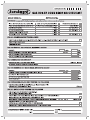
Benchmark gas boiler commissioning checklist ......54
1.1
Storage of documents
Please pass on these installation and maintenance
instructions and all other applicable documents to the
owner of the installation who is responsible for keeping
these documents for future reference when required.
1.2
Safety instructions and symbols
Please observe the safety instructions in this manual for
the installation of the appliance!
The symbols used in the manual are explained below:
d Danger!
Immediate risk of serious injury or death!
e Danger!
Danger of death by electric shock!
H Danger!
Danger of burning or scalding!
a Caution!
Potentially dangerous situation for the product
and environment!
h Note!
Useful information and instructions.
• Symbol for a necessary task
1.3
Validity of the instruction manual
These installation instructions apply exclusively to the
boiler with the following part number:
1
Notes on the documentation
The following instructions are intended to help you
throughout the entire documentation.
Further documents apply in combination with this
installation and maintenance manual.
We accept no liability for any damage caused by
non-observe these instructions.
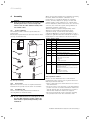
Type designation
ecoTEC VU GB 656/4-5 H
Article number
00 1000 4140
Table 1.1 Type designation and article number
The article number of the boiler can be found on the
identification plate.
Other applicable documents and service auxiliaries
• Always observe all installation instructions for
structural parts and components of the system when
installing the ecoTEC VU. These installation
instructions are enclosed with the various system
components as well as additional components.
• Also observe all the operating instructions included
with the system components.
Auxiliary service equipment:
The following test and measuring equipment is required
for inspection and maintenance:
– CO2 measuring instrument
– U tube manometer or digital
The manuals for any accessories and controllers used
also apply.
Installation and maintenance instructions ecoTEC 0020029173_01
3
2 Description of the boiler
2
2.1
Description of the boiler
Design
1
2
18
3
17
4
5
6
16
7
15
14
8
9
13
10
12
11
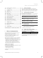
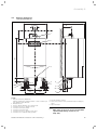
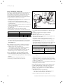
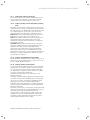
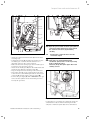
Fig. 2.1 Functional components
Legend:
1 Connection for the flue pipe
2 Heat exchanger
3 Air intake pipe
4 Compact thermal module with gas valve, fan,mixing tube,
burner door and burner
5 Ignition electrode
6 Water pressure sensor
7 Pump
8 Connection provision - filling (combined filling and emptying
valve)
9 Connection provision - expansion vessel
10 Electronic box
11 Siphon
12 Flow line drainage opening
4
13
14
15
16
17
18
Connection provision - expansion relief valve
Gas valve
Air separation system
Volume flow sensor
Automatic air vent
Flow switch with control lines
h Note!
When using accessories observe the minimum
separations/mounting clearances (see
Chap. 4.5).
Installation and maintenance instructions ecoTEC 0020029173_01
Description of the boiler 2
Safety instructions and regulations 3
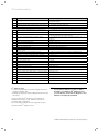
2.2
Type summary
Boiler type
Designated country
Category of permit
(designation in accordance with ISO 3166)
ecoTEC VU GB 656/4-5 H GB (Great Britain)
IE (Eire)
I2H
Type of gas
Nominal heat output range P
(kW)
Natural gas H
- G20 - 20 mbar
13,8 - 63,7 (80/60 °C)
14,1 - 65,7 (60/40 °C)
14,6 - 67,6 (50/30 °C)
14,9 - 69,2 (40/30 °C)
Table 2.1 Type summary
2.3
CE label
CE labelling shows that the appliances comply with the
basic requirements of the following directives:
– Gas appliances directive (90/396/EEC)
– Electromagnetic compatibility directive (Guideline
89/336/EEC of the council)
– Low voltage directive (Council Directive 73/23/EEC)
– Effectivity guideline (Council Directive 92/42/EEC) as
condensing boiler.
The manufacturer/supplier will not be held liable for
claims resulting from improper use. The user alone
bears the risk.
Intended use also includes observance of the operating
and installation manual and the inspection/maintenance
conditions.
a Caution!
Any form of misuse is prohibited.
2.5
Identification plate
The data badge of the Valliant ecoTEC is attached at the
factory to the bottom of the boiler.
3
h Note!
Vaillant Ltd. supports the Benchmark Initiative.
You will find the Benchmark Logbook on the
last page of this instruction manual. It is very
important that this document be filled out
properly when installing, commissioning and
handing-over to the operator of the installation.
2.4
Intended use
The Vaillant ecoTEC boiler has been constructed using
state-of-the-art technology in accordance with
recognised safety regulations. Nevertheless, there is still
a risk of injury or death to the user or others or of
damage to the boiler and other property in the event of
improper use or use for which it is not intended.
The Vaillant ecoTEC boilers mentioned in this manual
may only be installed and operated in conjunction with
the accessories listed in the associated flue system
installation manual (see Chap. "Other applicable
documents and service auxiliaries").
This boiler is not intended for use by persons (including
children) having limited physical, sensory or mental
capacities or who have inadequate experience and/or
knowledge, unless supervised by a person responsible
for their safety or who has been given instructions from
them as to how to operate the boiler. Children must be
watched to ensure that they do not play with the boiler.
The boiler is intended for use as a heater in closed hot
water central heating installations. Any other or
additional use is considered to be improper.
Installation and maintenance instructions ecoTEC 0020029173_01
3.1
Safety instructions and regulations
Safety instructions
3.1.1
Installation and setting
Assembly, adjustments and maintenance and repairs to
the boiler may only be carried out by a recognised
skilled trade company.
a Caution!
To tighten or loosen screw connections, only
use suitable open-ended spanners (do not use
pipe spanners, extensions, etc.).
Improper use or unsuitable tools can cause
damage, such as gas or water leaks.
3.1.2 Gas odour
If you smell gas, the following safety instructions must
be observed:
• Open doors and windows wide, provide for ventilation,
stay out of rooms where smell of gas is present!
• Avoid naked flames, do not smoke, do not use pocket
lighters!
• Do not use electric switches, plugs, doorbells,
telephones and other communication systems in the
building!
• Close gas meter isolator device or main isolator
device!
• Warn other building residents, but do not ring
doorbells!
• Vacate the building!
• If a gas leak is audible, immediately leave the building,
prevent others from entering the building, notify the
police and fire brigade from outside the building!
5
3 Safety instructions and regulations
• Notify the gas supply company or National Grid
Transco 0800 111999 by telephone from outside the
building!
3.1.3 Changes to the surroundings of the boiler
Changes may not be made to the following equipment:
– the heating appliance,
– gas, supply air, water and power lines– flue gas
removal system,
– drain line and expansion relief valve for heating water,
– constructional conditions that could affect the
operational reliability of the boiler.
3.2
General requirements
3.2.1 Related documents
The installation of the boiler must be in accordance with
the relevant requirements of Gas Safety
(Installation and Use) Regulations 1998, Health and
Safety Document No. 635 (The Electricity at Work
Regulations 1989), BS7671 (IEE Wiring Regulations) and
the Water Supply (Water Fitting) Regulations 1999, or
The Water Bylaws 2000 (Scotland). It should also be in
accordance with the relevant requirements of the Local
Authority, Building Regulations, The Building
Regulations (Scotland). The Building Regulations
(Northern Ireland) and the relevant recommendations of
the following British Standards:
BS 6700: Services supplying water for domestic use
within buildings and their curtilages.
BS 6798: Specification for installation of gas fired
boilers not exceeding 60 kW input.
BS 6891: Specification for installation of low pressure
gas pipework up to 28 mm (R1) in domestic
premises (2nd family gas).
BS 7593: Treatment of water in domestic hot water
central heating systems.
Institute of Gas Engineers Publication IGE/UP/7/1998:
„Guide for gas installations in timber framed housing”
BS. 5482 Pt. 1 Domestic butane and propane gas
burning installations.
IGE/UP1 Soundness testing and purging of industrial
and commercial gas installation.
IGE/UP2 Gas installation pipework, boosters and
compressors on industrial and commercial
premises. IGE/UP10 Installation of gas
appliances in industrial and commercial
premises.
BS. 6644 Installation of gas fired hot water boilers of
rated inputs between 60 kW and 2 MW
(2nd and 3rd family gases).
BS. 5449 Forced circulation hot water central heating
systems for domestic premises. Note: only up
to 45 kW.
BS. 6880 Low temperature hot water heating systems
of output greater than 45 kW.
6
Part 1 Fundamental and design
considerations.
Part 2 Selection of equipment.
Part 3 Installation, commissioning and
maintenance.
BS. 4814 Specification for: Expansion vessels using an
internal diaphragm, for sealed hot water
heating systems.
BS. 5440 Installation and maintenance of flues and
ventilation for gas appliances of rated input
not exceeding 70 kW net (1st, 2nd and 3rd
family gases).
Part 1 Specification for installation of flues.
Part 2 Specification for installation and
maintenance of ventilation for gas
appliances.
Furthermore it is essential that the boiler is installed,
operated and maintained in accordance with the current
state of the art. This applies likewise to the hydraulic
system, the flue gas installation and the installation site.
3.2.2 Installation site
The location chosen for the boiler must permit the
provision of a satisfactory flue termination. The location
must also provide adequate space for servicing and air
circulation around the boiler. The boiler may be installed
in any room, although particular attention is drawn to
the requirements of BS 7671 (IEE Regulations), the
electrical provisions of the Building Regulations
(Scotland) and in IE the current edition of IS 813 and the
current ETCI rules, in respect of the installation of a
boiler in a room containing a bath or shower.
h Note!
Where a room sealed boiler is installed in a
room containing a bath or shower, any
electrical switch or boiler control utilising
mains electricity should be so situated that it
cannot be touched by a person using the bath
or shower.
Where the installation of the boiler will be in an unusual
location, special procedures may be necessary and
BS 5546 and BS 6798 give detailed guidance on this
aspect. The boiler must be mounted on a flat, vertical
wall, which must be sufficiently robust to take the
weight of the boiler. The boiler may be installed on a
combustible wall, subject to the requirements of the
Local Authorities and Building Regulations. A
compartment used to enclose the boiler must be
designed and constructed specifically for this purpose.
(An existing cupboard or compartment may be used
provided that it is modified for the purpose). Details of
essential features of cupboard/compartment design
including airing cupboard installations are given in
BS 6891. In IE the current edition of IS 813.
Installation and maintenance instructions ecoTEC 0020029173_01
Safety instructions and regulations 3
h Note!
If the boiler is to be installed in a timber framed
1103
15
building, it should be fitted in accordance with
"IGE/UP/7 Edition 2 Gas installations in timber
framed and light steel framed buildings".
Flue pipe
d Danger!
Vaillant appliances are only system-certified if
genuine Vaillant flue pipes are used. Only use
genuine Vaillant flue pipes. Malfunctions can
occur if you use other accessories. These may
result in damage and injury. You will find a list
of genuine flue pipes in the Vaillant installation
manual for flue pipes. The CE mark is valid only
if the appliance is operated with Vaillant flue
pipes.
Only for commercial appliances:
For boiler installations in cascade arrangement using
the appliance type B23p a common non-Vaillant flue
system serving more than one appliance shall be used.
The requirements of the flue installation instructions
must be met.
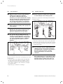
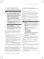
3.3.1 Standard 125 mm flue pipe
All ecoTEC boilers feature an 80/125 mm diameter air/
flue gas connection as standard. The selection of the
optimum system depends on the individual installation
and application conditions.
A more detailed description can be found in the
accompanying flue pipe installation manual.
For example, you can combine the following air/ flue
gas accesories with your boiler:
Concentric system, plastic, Ø 80/125 mm
• Install the flue pipe using the installation instructions
supplied with this appliance.
Installation and maintenance instructions ecoTEC 0020029173_01
70
3.3
Fig. 3.1 Item No. 303 209
1430
3.2.3 Gas supply
The gas supplier should ensure the availability of
sufficient gas volume. A gas meter may only be
connected to the service pipe by the supplier of gas or
their contractor. An existing meter should be checked to
ensure that it is capable of passing the rate of gas
supply required. Installation pipes should be fitted in
accordance with BS 6891. Pipework from the meter to
the boiler must be of an adequate size. Do not use pipes
of a smaller size than the boiler gas connection. The
complete installation must be tested for soundness and
purged as described in BS 6891.
70
70
Fig. 3.2 Item No. 303 200
3.3.2 Flue termination
The following details refer to both flue systems.
a. The terminal must be positioned such that the
products of combustion can disperse freely at all
times.
b. A plume of water vapour will sometimes be visible
from the flue terminal. Positions where this could be
a nuisance should be avoided.
c. If the terminal is fitted less than 2 m above a balcony,
above ground or above a flat roof to which people
have access then a suitable terminal guard must be
provided and fitted (contact Tower Flue Components,
Tonbridge, TN9 1TB).
h Note!
Vertical flues must not terminate within
600 mm of an openable window, air vent or any
other ventilation terminal.
7
3 Safety instructions and regulations
Q
I
Q
Q
P
F
D, E
G
A
I
N
O
C
M
B
L
N
H
H
M
J
K
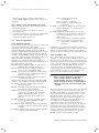
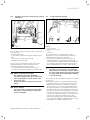
Fig. 3.3 Termination of the flue pipe
The flue assembly shall be so placed or shielded as to
prevent ignition or damage to any part of the building.
Location
A
B
C
D
E
F
G
H
I
J
K
L
M
Directly below an opening, air brick, opening windows, etc.
Above an opening, air brick, opening window, etc.
Horizontally to an opening, air brick, opening
window, etc.
Below temperature-sensitive building components e.g. plastic gutters, soil pipes or drain pipes
Below eaves
Below balconies or car port roof
From a vertical drain pipe or soil pipe
From an internal or external corner
Above ground, roof or balcony level
From a surface facing the terminal
From a terminal facing the terminal
From an opening in the car port (e.g. door, window) into the dwelling
Vertically from a terminal on the same wall
Minimum
dimensions
300 mm
300 mm
300 mm
75 mm
200 mm
200 mm
150 mm
200 mm
300 mm
600 mm
1200 mm
1200 mm
1500 mm
N Horizontally from a terminal on the same wall
300 mm
O From the wall on which the terminal is mounted
N/A
P From a vertical structure on the roof
N/A
Q Above intersection with roof
300 mm
Table 3.1 Position of the termination in a fan-assisted
concentric flue pipe
8
h Note!
In addition, the terminal should not be nearer
than 300 mm to an opening in the building
fabric formed for the purpose of
accommodating a built–in element such as a
window.
BS 5440–1 It is recommended that the fanned flue
terminal should be positioned as follows:
a) at least 2 m from an opening in the building directly
opposite, and
b) so that the products of combustion are not straightly
directed to discharge across a boundary.
1) Dimensions D, E and F:
These clearances may be reduced to 25 mm without
affecting the performance of the boiler. In order to
ensure that the condensate plume does not affect
adjacent surfaces the terminal should be extended as
shown in fig. 3.3.
2) Dimension H:
This clearance may be reduced to 25 mm without
affecting the performance of the boiler. However, in
order to ensure that the condensate plume does not
affect adjacent surfaces a clearance of 300 mm is
preferred. For IE, recommendations are given in the
current edition of IS 813.
Installation and maintenance instructions ecoTEC 0020029173_01
Safety instructions and regulations 3
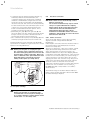
Balcony/eaves
Gutter
Flue pipe
adequately fixed
Flue pipe must project
beyond every overhang
Fig. 3.4 Termination of flue pipe under balcony or eaves
3.4
Air supply
Detailed recommendations for air supply are given in
BS 5440: Part 2. It is not necessary to have an air vent
in the room or internal space in which the boiler is
installed.
3.5
Compartment ventilation
The boilers are very high efficiency appliances. As a
consequence the heat loss from the appliance casing
during operation is very low. Compartment ventilation is
required if the flue used is not concentric and air is
supplied from the room or compartment the boiler is
installed in.
3.6
Electrical supply
A 230 V, ~ 50 Hz single phase electricity supply fused to
3 Amp. must be provided in accordance with the latest
edition of BS7671 (IEE Wiring Regulations) and any other
local regulations that may apply. In IE reference should
be made to the current edition of the ETCI rules. The
method of connection to the mains electricity supply
must provide a means of completely isolating the boiler
and its ancillary controllers. Isolation is preferably by
the use of a fused three pin plug and unswitched
shuttered socket outlet, both complying with the
requirements of BS 1363. Alternatively, a 3 Amp. fused
doublepole switch with a 3 mm contact separation on
both poles may be used.
Danger!
Risk of fatal electric shock!
The boiler must be earthed.
Installation and maintenance instructions ecoTEC 0020029173_01
9
4 Assembly
4
Assembly
a Caution!
Flush the heating installation thoroughly before
installing the boiler to remove foreign substances such as solder and flux residue, leftover sealant or dirt.
4.1
Scope of delivery
The Vaillant ecoTEC is delivered pre-mounted in a
package unit.
Check that all parts have been delivered and are intact
(see Fig. 4.1 and Table 4.1).
1
Installation instructions
ecoTEC
10
When choosing the installation site and while operating
the boiler, make sure that the combustion air is
technically free of chemical substances containing
fluorine, chlorine, sulphur etc. Sprays, solvents and
cleaning agents, paints, adhesives etc. contain these
kinds of substances, which in the worst case can lead to
corrosion, also in the flue system, during ambient air
dependent operating of the boiler.
The boiler must be operated independently of the
ambient air, particularly in hairdressing salons,
carpenter‘s shops, or paint shops and cleaning
companies. Otherwise, a separate installation room is
required to guarantee that the combustion air supply is
technically free of the substances mentioned above.
Position Number Name
1
1
Hanging bracket
2
1
Boiler
Installation instructions
ecoTEC
Installation instructions
ecoTEC
2
9
8
3
1
Installation kit for siphon cartridge
4
1
Expansion relief valve
5
1
Gas isolation valve
6
2
Stop cocks
7
1
Condensate drainage hose
8
1
Bag containing hardware (assembly kit):
- 2 wood screws
- 2 wall plugs 10 x 60 mm
- 2 washers
- 1 seal
- 1 crimp connection
9
1
Tool for the gas valve
10
1
Bag with printed documents:
– Installation and maintenance instructions
– Operating manual
– Installation instructions, air/flue gas duct
system
- Installation template
- Miscellaneous stickers
3
ecoTEC
3
1
a.
2
1/3
b.
835311_00
102004
c.
2/3
7
4
6
5
Table 4.1 Scope of delivery
2x
Fig. 4.1 Scope of delivery
4.2
Accessories
Optional accessories for use in conjunction with the
installation and operation of the boiler are available.
4.3
Installation site
Please note the safety instructions below before
choosing where to install the boiler:
Select position of boiler
Refer to section ‘Installation site’ for information
regarding the siting of the boiler. In general the boiler
must be positioned such that:
• There is sufficient space around the boiler for service
and maintenance.
• The boiler can be correctly flued, i.e. the flue terminal
position is sited in accordance with these instructions
and the air/flue duct can be installed in accordance
with the flue installation instructions supplied.
• All necessary pipework can be connected, including
the pressure relief valve and condensate drain.
a Caution!
Do not install the boiler in rooms prone to frost.
In rooms with aggressive steam or dust, the
boiler must be operated independently of the
ventilation!
10
Installation and maintenance instructions ecoTEC 0020029173_01
Assembly 4
4.4
Dimension drawing and
connection dimensions
480
472
Ø 80/125
211
94
119
A
1
800
2
4
5
Ø 25, R1
7
Rp 1
6
G 1 1/2
R 3/4
Rp 1
G 1 1/2
172
172
R1
140
61
32
3
8
9
10
75
121
224
224
11
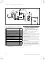
Fig. 4.2 Connection dimensions in mm
Legend:
1 Flue gas connection, 80/125 mm
diameter, dimension A (hanging bracket – centre of air/flue gas
pipe) with 87° elbow: 297 mm
2 Hanging bracket
3 Gas pipe, 25 mm diameter, gas connection R1“
4 Connection provision - expansion vessel
5 Connection for heating return
6 Connection for heating flow
7 Connection provision - expansion relief valve
8 Connection for condensate drain pipework
Installation and maintenance instructions ecoTEC 0020029173_01
9 Flow line drainage opening
10 Connection provision - filling (combined filling and emptying
valve)
11 Siphon cartridge
h Note!
When using accessories observe the minimum
separations/mounting clearances (see
Chap. 4.5).
11
4 Assembly
4.5
Required minimum gaps/assembly clearances
For the installation/assembly of the boiler as well as for
carrying out future maintenance tasks, you need the
minimum gaps and assembly clearances given below:
4.7
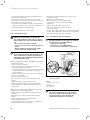
Mounting the boiler
d Danger!
Danger of personal injury and damage to
property from falling boiler!
When assembling the boiler make sure that the
fixing point has a sufficient load-bearing
capacity. Also take the condition/nature of the
wall into account.
500
270
175
75
44
25
1
2
400
Fig. 4.3 Required minimum gaps/assembly clearances
It is not necessary to ensure sufficient clearance
between the boiler and combustible materials or
components as the temperature of the boiler will always
be less than the maximum permissible temperature of
85 °C due to its rated heating output.
3
Fig. 4.4 Mounting the boiler
4.6
Using the installation template
Only use the assembly template provided to mount the
boiler.
• Align the installation template vertically and fix it to
the wall.
• Mark the positions of the drill holes for the hanging
bracket and also the position of the wall opening for
the flue pipe on the wall.
• Remove the assembly template from the wall.
• Drill 2 holes for the hanging bracket in the wall, each
with a diameter of 8 mm.
• If necessary cut the aperture in the wall for the flue
pipe.
12
• Mount the hanging bracket (1) on the wall using the
wall plugs and screws (2) provided with the boiler.
• Hang the boiler (3) on the hanging bracket from
above using the suspension bracket.
Installation and maintenance instructions ecoTEC 0020029173_01
Assembly 4
Installation 5
4.8
Removing/attaching the front casing
5
Installation
d Danger!
Danger of injury to persons and/or material
damage due to improper installation!
The Vaillant ecoTEC boiler may only be
installed by a recognised skilled trade company.
who also assumes the responsibility for proper
installing and initial start-up of the boiler.
2
1
Take particular care to fit the siphon cartridge during
installation.
a Caution!
The ecoTEC VU 656 must be used with a
suitably sized low loss header.
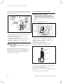
Fig. 4.5 Removing the boiler casing
To dismount the front casing of the boiler, proceed as
follows:
• Unfasten the screw (1) on the bottom of the boiler.
• Push in both retaining clips (2) on the bottom of the
boiler so that the front casing is released.
• Pull the casing forwards by its bottom edge and lift
the casing up and off.
To mount the front casing of the boiler, please proceed
as follows:
• Place the casing on the upper boiler ensuring that the
casing and boiler lips engage.
• Push the casing onto the boiler so that the retaining
clips (2) on the casing click into place.
• Fix the casing by tightening the screw (1) on the
bottom of the boiler.
3
4
1
2
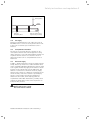
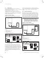
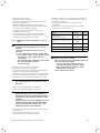
Fig. 5.1 Appliance circuit and heating circuit/cylinder charging
circuit
Legend:
1 Boiler with pump
2 Low loss header
3 Consumer (e.g. heating circuit)
4 Cylinder
h Note!
We strongly recommend the installation of a
suitably sized quality dirt separator in the
return pipe work to the low loss header (not to
the boiler!) particularly in the case of old
systems. This will help to prevent any system
water contamination from entering and blocking
the boiler and producing an additional high
pressure loss.
Installation and maintenance instructions ecoTEC 0020029173_01
13
5 Installation
Selection of the low loss header
The low loss header uncouples the boiler from the
heating system. A sufficiently large water volume is
constantly supplied through the boiler via the low loss
header in conjunction with the boiler pump. It acts as a
neutral point in the system and has minimal hydraulic
resistance, therefore the boiler pump does not affect
the circuit pumps and vice-versa.
A suitable WH type low loss header can be chosen from
Table 5.1.
Temperature difference of heating system
Output of heating
system
Stand-alone boiler
Two cascade
arrangement
Three cascade
arrangement
10 K
15 K
20 K
WH 160
WH 95
WH 95
WH 280
WH 160
WH 95
WH 280
WH 280
WH 160
Table 5.1 Selection of the low loss header
No electrical accessories are required in order to use a
low loss header. Simple systems can be connected
directly inside the electronic box.
Model
Articlenumber
Connection
Sizes
1
2“ BSP (f)
Header
width
A
155
Header
depth
B
155
Total
height
C
750
Insulation
dimensions
WH 95
306721
WH 160
306726
DN65
520*
120
1350
220/220
900
900
300
12
WH 280 306725
DN80
600*
160
1390
260/260
930
930
300
21.5
155/155
To boiler To heating Height from
circuit
floor
D
E
F
470
540
n/a
Maximum
volume flow
m3/hr
8
Table 5.2 Low loss headers dimensions
All dimensions in mm
* = distance between flanges
14
Installation and maintenance instructions ecoTEC 0020029173_01
Installation 5
Safety devices
• The outlet of the pressure relief valve must be
suitably terminated in accordance with BS 6798 or
BS 6644.
• The boiler is suitable for connection to plastic
centralheating pipes. It is preferred that the
connections to the boiler are made in copper for the
first 1.5 metres prior to the transition to plastic.
• Should a system be found to include non-oxygen
barrier pipe then it is essential that a plate heat
exchanger be installed in between the boiler and the
non-oxygen barrier pipe. It is essential that the boiler
and the system have provision for water make up and
expansion.
For more detailed information on examples of systems
and system equipment contact your Vaillant sales
support point.
d Danger!
Danger of personal injury and material damage!
The following system diagrams are schematic
representations. They cannot be regarded as a
substitute for professional planning! The
system diagrams do not include the isolator
and safety devices that are required to carry
out a professional installation. Observe the
applicable standards and guidelines.
The boiler can be installed in three different
configurations:
• heat only,
• cylinder only, and
• heating and cylinder.
Fig. 5.2 Low loss header
Installation and maintenance instructions ecoTEC 0020029173_01
15
5 Installation
5.1
Heating mode
In case of only one heating circuit to be operated
downstream of the low loss header, this one can directly
be controlled by the ecoTEC.
A suitable pump can be selected and installed
downstream of the low loss header. You can select a
pump that fits to your system. In case of systems with
multiple circuits please pay attention to the additional
control system accessories.
Hydraulic schematic drawing:
Heating circuit connection using low loss header
The low loss header ensures, in conjunction with the
boiler circulation pump, that a sufficiently high minimum
quantity of water is always circulating through the
boiler.
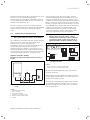
5.2
Cylinder charging mode
The electronics of the ecoTEC are designed in such a
way that one cylinder charging circuit and one heating
circuit can be connected directly without the need for
accessories. As the charging circuit is connected downstream of the low loss header this means that the size
of the cylinder and the specific cylinder primary pump
can be selected according to individual requirements.
h Note!
Observe that non-return valves or mixer
circuits may be required in order to eliminate
cross-flow to other circuits or the effects of
high temperatures from the charging circuit.
4
Hydraulic schematic drawing:
Hot water priority via low loss header
1
3
2
4
Fig. 5.3 Heating circuit connection using low loss header
Legend:
1 Boiler with internal pump
2 Low loss header
3 External heating pump
4 Consumer (e.g. heating circuit)
3
1
2
8 9
LN
3 4 5
X18
X13
1
Fig. 5.5 Hot water priority via low loss header
Legend:
1 Boiler with internal pump
2 Low loss header
3 External heating pump
4 Consumer (e.g. charging circuit)
X14
X11
X6
Fig. 5.4 Electrical connection for heating pump downstream of
the low loss header
The settings for the internal pump are made at the
factory. The pump output can be reset to your own
requirements via diagnosis point "d.14", see Chap. 9.1.2.
Use the grey ProE plug to establish the electrical connection with the external heating pump. To assign the
"external heating pump" function to the plug (1)
(additional relay) the value "2" must be specified at
diagnosis point "d.26" in the 2nd diagnosis level, see
Chap. 9.1.2.
16
8 9
LN
X14
3 4 5
X18
X13
1
X11
X6
Fig. 5.6 Electrical connection for cylinder charging pump
Installation and maintenance instructions ecoTEC 0020029173_01
Installation 5
Use the mounted ProE plug (1) to establish the electrical
connection for the cylinder charging pump.
The pink plug-in location X6 (1) on the PCB is reserved
for the cylinder primary pump. It is not necessary to do
settings at any diagnosis point.
The low loss header ensures, in conjunction with the
boiler circulation pump, that a sufficiently high minimum
quantity of water is always circulating through the
boiler.
5.3
h
A direct heating circuit and one hot water cylinder
(including charging pump and non-return valve) can be
connected downstream of the low loss header to the
ecoTEC boiler without additional equipment. If additional
heating circuits are required this can be achieved with
the use of optional controllers and hydraulic accessories
(e.g. VRC 630). The available pump head from the boiler
is sufficient to pump water around the shunt circuit
between the boiler and low loss header. All heating
circuits and hot water cylinder configurations can be
connected downstream of the low loss header.
Heating mode and charging mode
Note!
Also observe Chap. 5.1 and 5.2 of this manual.
The combination of heating mode and cylinder charging
mode of the boiler can not be equated with either
heating mode or cylinder charging mode.
For faultless operation, both operating modes must be
carefully planned for the system. The boiler is
uncoupled from the consumer circuits by the low loss
header. This means that the circuits downstream of the
low loss header can be designed according to individual
requirements (pump dimension, cylinder position).
Hydraulic schematic drawing:
Hot water priority and heating circuit via low loss
header
h Note!
Observe that non-return valves or mixer
circuits may be required in order to eliminate
cross-flow to other circuits or the effects of
high temperatures from the charging circuit.
8 9
LN
X14
3 4 5
X18
X13
2
1
X11
X6
Fig. 5.8 Electrical connection for cylinder primary pump and
external heating pump
Legend:
1 Plug-in location for cylinder primary pump
2 Plug-in location for external heating pump
6
4
1
3
5
Use the relevant mounted ProE plug to perform the
electrical connection.
The pink plug-in location X6 (1) on the PCB is reserved
for the cylinder primary pump. It is not necessary to do
settings at any diagnosis point.
2
Fig. 5.7 Hot water priority and heating circuit via low loss
header
To assign the "external heating pump" function to the
grey plug (2) (additional relay) the value "2" must be
specified at diagnosis point "d.26" in the 2nd diagnosis
level, see Chap. 9.1.2.
Legend:
1 Boiler with internal pump
2 Low loss header
3 External heating pump
4 Consumer (e.g. heating circuit)
5 External cylinder primary pump
6 Cylinder
Installation and maintenance instructions ecoTEC 0020029173_01
17
5 Installation
5.4
5.5
Gas connection
d Danger!
Danger of injury to persons and/or material
damage due to improper installation!
The Vaillant ecoTEC boiler may only be
installed by a recognised skilled trade company
who also assumes the responsibility for proper
installation and initial start-up of the boiler.
The legal directives and the local regulations
for gas supply companies must be observed.
Heating connection
a Caution!
Ensure strainless assembly of the supply lines
to avoid leakages in the heating system!
The boiler is connected to the heating flow and return
via service valves.
a Caution!
Ensure strainless assembly of the gas pipes to
1
avoid leakages!
h Note!
Maintain the same gas pipe dimension all the
way to the boiler and avoid reducing the
dimension downstream of the gas meter.
a Caution!
The gas valve may be damaged if the test
pressure or operating pressure is exceeded!
You must check the tightness of the gas valve
only using a maximum pressure of 110 mbar!
The operating pressure must not exceed
60 mbar!
4
2
3
Fig. 5.10 Heating connection
• Fit the flow, return and gas isolation valves (2, 3, 4)
including the seals onto the flow, return and gas pipes.
Do not overtighten and ensure the joints are checked
for leaks after fitting.
a Caution!
It is essential to use the combined filling and
1
Fig. 5.9 Fitting the gas connection
The boiler must be connected to your gas pipe via a gas
isolation valve.
• Screw the boiler‘s gas supply pipe (1) gas-tight with
the gas isolation valve (3, see Fig. 5.10). To do this,
use the R3/4 compression fitting supplied with the
boiler. This is suitable for the connection of a R3/4
gas isolation valve.
• Inspect the gas connection for leakage.
18
emptying valve (1) in the return for filling the
boiler without fail, as otherwise the bleeding of
the boiler cannot be ensured. You must
implement the filling in accordance with
standards.
h Note!
We recommend the use of seals made of a fibrebased material similar to cardboard instead of
materials similar to rubber as the latter can
plastically deform and cause pressure losses.
Installation and maintenance instructions ecoTEC 0020029173_01
Installation 5
5.6
Expansion relief valve (safety group), heating
installation
5.7
Condensate drain pipework
1
1
2
2
a
b
c
d
5
3
3
4
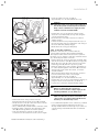
Fig. 5.11 Fitting the safety valve
The ecoTEC is equipped ex factory with connections for
a safety group:
• Pressure gauge (1)
• Filling device (combined filling and emptying valve)
(2)
• Connection for expansion vessel (3)
• Expansion relief valve (4)
As an accessory the expansion relief valve for the
heating installation is delivered with the boiler.
• Install the expansion relief valve (4).
• Fit a sufficiently sized expansion vessel (to be
provided on site) at the designated connection (3).
H
Danger!
Danger of burning and scalding!
The expansion relief valve (4) must be
noticeable! Terminate the line in such a way
that escaping water or steam cannot cause
injury to persons.
Please note that the end of the line must be
visible.
a Caution!
Risk of damage!
The line should be terminated in such a way
that cables or other electrical components
cannot be damaged.
Installation and maintenance instructions ecoTEC 0020029173_01
3
4
6
Fig. 5.12 Condensate drain pipework
Legend:
a Internal stackpipe
b Internal discharge system
c Gully
d Soakaway
The ecoTEC boilers are equipped with a usual
condensate collector from which the condensate is
continuously removed via the drain pipe.
• Connect the condensate drain of the boiler to a
condensate drain hose (1) which has a minimum
internal diameter of 19 mm (22 mm outside diameter
for all external pipes) and should be made from an
acid-resistant material (e.g. plastic overflow pipe).
h Note!
The drain hose connected to the condensate
drain of the boiler must have a fall throughout
its entire length (45 mm per metre) and should
be installed and connected within the building
to prevent freezing.
The condensate drain hose must terminate in a suitable
location, e.g.:
a)Preferably the drain hose should run and terminate
internally to the house soil and vent stack (at least
450 mm above the invert of the stack). A siphon
giving a water seal of at least 75 mm (3) (built into
the boiler) should be incorporated into the pipe run,
and there must be an air break (2) in the drain hose
upstream of the siphon. The connection to the stack
should not be made in a way that could cause cross
flow into any other branch pipe, or from that branch
pipe into the condensate drainpipe. This can be
achieved by maintaining an offset between branch
pipes of at least 110 mm on a 100 mm diameter stack
and 250 mm on a 150 mm diameter stack.
19
5 Installation
b) connecting into the internal discharge branch (e.g.
sink waste) with an external termination, the
condensate draining pipe should have a minimum
diameter of 22 mm with no length restriction and
should incorporate a siphon with a 75 mm (3) (built
into the boiler) seal. The connection should preferably
be made down stream of the sink waste siphon. If the
connection is only possible upstream, then an air
break is needed between the two siphons. This is
normally provided by the sink waste.
c) terminating in a gully (4) below grid level (5) and
above the water level. The external pipe length should
be kept as short as possible to minimise the risk of
freezing and should not be more than 3 m.
d) at a condensate absorption point (soakaway) (6). The
external pipe length should not be more than 3 m.
Further information can be obtained from "BS 6798
Specification for installation of gas–fired boilers of rated
input not exceeding 70 kW net“.
d Danger!
Risk of poisoning due to escaping flue gas!
The connection of the condensate drain line to
the waste water piping must not be fixed as the
internal siphon could be sucked dry. Before the
boiler is switched on the siphon must have been
filled with water to prevent flue gas from
leaking via the siphon (see Chap. 6.2.3).
1
5.8
Electrical connection
e Danger!
Risk of fatal electric shock through contact
with live connections!
The electrical installation may only be carried
out by a recognised skilled trade company.
Always switch off the power supply first and
ensure that it cannot be switched back on
unintentionally. Only after this can the
installation be undertaken. Mains connection
terminals L and N remain live even if the boiler
main switch is turned off!
5.8.1 Mains connection
All electrical work shall be carried out by a heating
engineer and shall comply with BS 7671 (IEE
Regulations).
In the Republic of Ireland, reference should be made to
the current edition of the ETCI (Electro-Technical
Council for Ireland) rules.
The boiler is supplied for connection to 230 V, ~ 50 Hz
supply fused at 3 A rating. Connection to the mains
supply shall be made via a fused 3 pin plug to an
unswitched shuttered socket, both complying with the
requirements of BS 1363. (Alternatively, connection may
be made via a 3 A fused double pole isolator having a
contact separation of at least 3 mm in all poles and
supplying the boiler and controllers only). The point of
connection to the mains supply must allow complete
electrical isolation of the boiler and its ancillary
controllers. It should be readily accessible and adjacent
to the boiler. A 3 core flexible cord according to
BS 6500 tables 6,8 or 16 (3 x 0.75 to 3 x 1.5 mm2)
should be used.
The nominal voltage of the mains must be 230 V; at
mains voltages greater than 253 V and less than 190 V
the functions may be impaired.
Fig. 5.13 Siphon cartridge
d Danger!
Risk of poisoning due to escaping flue gas!
You must fit the enclosed siphon cartridge (1)
in accordance with the separate manual and fill
it with water - see also Chap. 6.2.3.
20
Installation and maintenance instructions ecoTEC 0020029173_01
Installation 5
• Cover the supply line over a length of
approximately 2 - 3 cm and insulate the cores.
4
a Caution!
Supplying power to the wrong plug terminals of
the Pro E system can destroy the electronics.
Only connect a 230 Vac live supply to boiler
terminal connections marked LNE.
1
2
3
5.8.2 Connecting controllers
Mount the controllers in accordance with the
corresponding operating and installation manuals.
The required connections to the electronic system of
the boiler (e.g. for external controllers, external sensors
etc.) should be performed as follows:
• Remove the front casing of the boiler (see Chap. 4.8)
and tilt the electronic box (2) forwards (see Fig. 5.14).
• Unclip the rear cover (1) of the electronic box at the
fastening points (3) and lift it up (see Fig. 5.14)
• Guide the supply lines of the relevant components to
be connected through the cable ducts (4). Leave the
existing seals in the other cable ducts, to seal the
vacuum chamber.
• Then feed the mains supply lines into the electronic
box and cut the lines to the correct length.
• Cover the supply line over a length of
approximately 2 - 3 cm and insulate the cores.
• Connect the cores to the corresponding ProE plugs, or
plug-in locations of the electronics, as shown in
Fig. 5.15 (see connection diagram in Chap. 5.8.5).
Fig. 5.14 Opening back wall of the electronic box
-
+
7 8 9
LN
3 4 5
BUS
-
+
7 8 9
• Connect the cores to the plug-in locations in the
electronics (L, N and Earth), see Fig. 5.15, using the
corresponding ProE plug.
• Close the rear cover of the electronic box until it
audibly engages.
• Lift the electronic box up and press the two clips on
the left and right of the box against the side casing of
the boiler until they audibly engage.
• Mount the front casing (see Chap. 4.8).
LN
3 4 5
BUS
a Caution!
Danger of destroying the electronics!
Do not connect a mains voltage supply to the
following terminals: 7, 8, 9, eBUS (+,-)!
Fig. 5.15 Example for cable routing
• Remove the front casing of the boiler (see
Chap. 4.8) and tilt the electronic box (2) forwards.
• Unclip the rear cover (1) of the electronic box at the
fastening points (3) and fold it up.
• Use a commercially available mains connection cable.
• Guide the mains connection cable through a cable
duct (4). Use the grommet to seal the opening.
• Then feed the mains connection cable into the
electronic box and cut the line to the correct length.
Installation and maintenance instructions ecoTEC 0020029173_01
h Note!
Make sure that the electrical connections are
carried out in accordance with standards and
that they are mechanically secure.
• If a roomthermostat/timer is not connected, you must
insert a bridge between terminals 3 and 4, if not
already installed. Remove the bridge if you connect a
corresponding room/thermostat timer to terminals
3 and 4.
21
5 Installation
• If a weather-compensated or room temperature
control system is connected (continuous control
connection terminals 7, 8, 9) the bridge between
terminal 3 and 4 must remain inserted.
• Close the rear cover of the electronic box until it
audibly engages.
• Lift the electronic box up and press the two clips on
the left and right of the box against the side casing of
the boiler until they audibly engage.
• Mount the front casing (see Chap. 4.8).
• To access pump operating mode 1 (running on of
pump) for multi-circuit controllers, change the setting
at diagnosis point "d.18" (pump operating mode) from
3 "intermittent" to 1 "run on" (see Chap. 7.2.2).
Observe that the bridge at the ProE plug must be
removed when connecting a maximum thermostat
(flow thermostat) for underfloor heating.
Carry out the installation in accordance with the
corresponding operating and installation manual.
To actuate relay 1 at the the accessory module select
diagnosis point "d.27" at diagnosis level 2, and to
actuate relay 2 select diagnosis point "d.28"
(see Chap. 9.1.2). You can select the following
components here:
1
2
3
4
5
6
7
8
9
= circulation pump
= external pump
= charging pump
= vapour extraction hood
= external solenoid valve
= external error message
= not active
= remote control eBUS (not active)
= legionella pump (not active)
5.8.3 Connecting a low loss header sensor
The low loss header sensor must either be connected to
the X41/RF as per the connection diagram (Fig. 5.16) or
to the selected controller (see corresponding operating
manual).
5.8.4 Additional relay (grey plug on the PCB) and
"2 in 7“ multifunction module
Additional relay (grey plug on the PCB)
With the ecoTEC it is possible to actuate one additional
component via the additional relay. You can select the
installed components via diagnosis point "d.26" at
diagnosis level 2 (see Chap. 9.1.2).
VR40 - "2 in 7“ multifunction module
If you wish to connect additional components this can
be done using the Vaillant VR40 - "2 in 7" multifunction
module.
h Note!
Please observe the separate manual attached
to the VR40 - "2 in 7" multifunction module.
22
Installation and maintenance instructions ecoTEC 0020029173_01
Installation 5
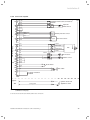
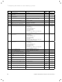
5.8.5 Connection diagrams
10
4
2
5
9
11
12
Cylinder thermostat (connection)1)
“C1-C2”
black
13
1
17
3
4
16
violet
black
1
2
4
red
green
black
Flow rate sensor
-
1 Earth
black
2 Hall signal
grey
3
4 PWM signal
red
5 +24V
10
18
9
15
black
Fan
natural
Flow sensor
black
Return sensor
black
black
black
Flow switch
blue
Gas valve
red
Coding resistance
1210 Ω
Igniter
X14
Water pressure sensor
blue
red
black
blue
black
2
P
+
Signal
green
5
7
8
12
13
14
X20
6
X11
Cylinder
NTC sensor1)
orange
red
X2
Low-voltage plug
brown
black
Mains
14
Ignition electrode
green/yellow
Appliance earth
Fig. 5.16 Connection diagram of ecoTEC
(continued on next page)
1) You must not use both the C1/C2 and the cylinder sensor connections!
Installation and maintenance instructions ecoTEC 0020029173_01
23
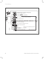
5 Installation
Internal pump
Boiler enable connection (factory link fitted)
N
L
230 volt mains input
9
8
7
Optional ext. controller/room thermostat 7-8-9
(continuous, analogue)
+
-
Bus connection for optional accesories
2
1
Safety circuit connection
0
0
DCF
RF
AF
6 FB
1
Earth
Earth
Connector
DCF connection
Low loss header sensor VRC 430
External sensor
Remote control, circulation pump
X22
230 V~
Mains voltage
5
4
3
(adjustable in d.26, see table 9.3)
white
X41
N
L
Additional relay (e.g. external heating pump)
red
X1
Low voltage
pink
X6
turqoise violet
X18
N
L
Cylinder
primary pump
N
L
24 V
X11
grey
N
L
green
X13
Edge connector blue
blue
Fan
230V~
for controller accessories
PWM signal, internal pump
Fan
Fig. 5.16 Connection diagram of ecoTEC (continued)
24
Installation and maintenance instructions ecoTEC 0020029173_01
Start-up 6
6
Start-up
a
Caution!
The boiler must only be operated with its
casing properly and permanently closed!
Otherwise, under unfavourable conditions, it
can result in material damage or even injury or
death.
6.2
Filling the system
6.2.1
Preparation of heating water
Caution!
a Do not add anti-freeze to the system water!
Addition of such can attack the boiler seals and
ultimately result in damage to the boiler and
cause noise during the heating operation.
Vaillant assumes no liability for this and such
consequential damages. Please ensure the
operator is aware of frost protection methods.
h Note!
When starting up particularly take the following
into consideration:
Before the heating circuit or charging circuit is
filled you must open the cap on the automatic
air vent which must remain open during
subsequent operation.
Use the bleeding program to bleed the heating
circuit or charging circuit (see Chap. 9.2).
6.1
Water circulation system
Detailed recommendations concerning the water circuit
system can be taken from BS 6798 and BS 5449, Part 1
(for "Small Bore” and "Micro Bore” central heating
systems). Lines which do not form part of the usable
heating surface should be insulated to prevent heat
losses and possible freezing up, especially where the
lines run under rooves and ventilated cellar rooms. The
drain connections must be easily-accessible, so that the
entire system including the boiler and hot water system
can be drained. The drain connections should be at least
1/2 " (BSP nominal size) and must be in accordance with
BS 2879.
The boiler is suitable for Minibore and Microbore
systems. Water lines are to be copper pipes in
accordance with BS 2871, Part 1. All capillary
connections in all the hot water lines must be carried
out with lead-free solder. These must be thoabout
cleaned, especially when connecting a new boiler to an
existing system.
a Caution!
To prevent deposition and severe damage to
the boiler and heating system the cleaning
agent must be applied carefully and subsequently removed from the heating system by
draining it completely. Cleaning agents should
not remain in the heating system longer than
24 hours.
This cleaning process must take place before a new
boiler is fitted in accordance with BS 7593.
Recommendations on the use of system cleaning agents
can be obtained from Sentinel, Betz Dearborn Ltd.
Widnes, Cheshire, WA8 8UD, Tel. 0151 420 9595, or
Fernox, Cookson Electronics, Forsyth Road, Sheerwater,
Woking, Surrey GU21 5RZ, Tel. 01483 793200.
Installation and maintenance instructions ecoTEC 0020029173_01
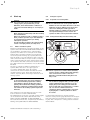
6.2.2
Filling and bleeding from the heating side
2
1
Fig. 6.1 Check the filling pressure of the heating system
a Caution!
Fill the system in accordance with standards,
and only via the combined filling and emptying
valve on the boiler's return connection.
Otherwise, problems with bleeding the boiler
may occur!
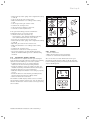
h Note!
The ecoTEC is equipped with a pressure gauge
(1) and a digital pressure indicator. You can
display the precise filling pressure when the
boiler is switched on by pushing the "-" button
(2). You can also switch between the
continuous display of temperature or pressure
by keeping the "-" button pushed for about
5 seconds.
For the heating installation to work properly the
indicator on the pressure gauge (1) must be in the upper
half of the dark grey area when the system is cold (see
Fig. 6.1). This corresponds to a filling pressure between
1.0 and 2.0 bar.
25
6 Start-up
If the heating installation serves several floors, the
values for the water pressure in the system may need
to be higher (to avoid the ingress of air).
• Flush through the heating system thoroughly before
actually filling it.
h Note!
Use the test program P.0 to bleed the heating
system: The boiler does not start up. The
internal pump runs intermittently and bleeds
the appliance circuit. The pressure is displayed
digitally. Ensure that the system pressure does
not fall below 0.8 bar when bleeding is in
progress. Otherwise the bleeding will not be
carried out properly. The bleeding program
takes about 6.5 minutes to complete.
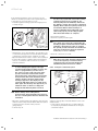
1
• Bleed all the radiators.
• Check the system pressure again.
a Caution!
If too much air is still in the system after the
bleeding program is finished it must be started
again! Once the filling procedure is complete
the system pressure should be at least 0.2 bar
above the back-pressure from the expansion
vessel (Psystem ≥ PADG + 0.2 bar).
Fig. 6.2 Automatic air vent
• Unfasten the cap on the automatic air vent (1) by one
or two turns (the appliance is bled automatically while
continuously operated via the automatic air vent).
• Open all thermostatic radiator valve in the installation.
• Connect the system's combined filling and emptying
valve to a cold water draw-off valve in accordance
with the standards.
h Note!
To avoid damaging the appliance through
operation with insufficient water pressure, the
boiler is equipped with a pressure sensor.
The sensor records a lack of pressure if the
pressure value falls below 0.6 bar and the
detected pressure value flashes in the display.
If the pressure falls below 0.3 bar the boiler
switches off. Error message F.22 ("water
shortage") appears in the display. Fill the
system up with water before you start up the
boiler again. This message also appears if you
switch the boiler on when it is empty and
disappears automatically when it is filled.
• Check all connections for leaks.
h Note!
When the boiler starts operating a maintenance
or error message may occur due to falling
system pressure. The message disappears
automatically when the boiler is refilled.
6.2.3
Filling the condensate siphon
1
a Caution!
Risk of damage from leaking water!
If the pressure drops frequently the reason for
the loss of heating water must be identified and
eliminated.
• Open the combined filling and emptying valve and the
draw-off valve slowly and add water until the required
system pressure is shown on the pressure
gauge/display.
• Turn the tap off.
26
Fig. 6.3 Filling the condensate siphon
A siphon cartridge (1) is included with the boiler as an
installation kit.
• Fit the siphon cartridge (1) in accordance with the
accompanying installation manual before filling the
condensate siphon.
Installation and maintenance instructions ecoTEC 0020029173_01
Start-up 6
h IfNote!
the installation kit is not present, do not
operate the boiler. Contact Vaillant customer
service.
d Danger!
If the boiler is operated with an empty
condensate siphon, there is danger of poisoning
through escaping flue gases. Therefore it is
mandatory to fill the siphon in accordance with
the accompanying description before start-up.
6.3
Checking the gas setting
a Caution!
Malfunctions or reduction in working life of the
• Check the maximum gas flow rate as detailed in
section 6.3.2.
• Check the gas inlet working pressure as detailed in
section 6.3.3.
• Note that you must re-measure the gas flow rate or
the gas inlet working pressure, if changes were
required to correct any issues found.
6.3.1
Checking for tightness of the flue gas
installation and flue gas recirculation
• Check the integrity off the flue gas installation
according to TB 200.
• Should the flue gas installation be longer than 2 m we
strongly recommend to check the system for flue gas
recirculation as described below.
boiler!
If the boiler version does not correspond to the
local gas family, there will be malfunctions or
you have to change components of the boiler
ahead of schedule, e. g. do not use a LPG boiler
on natural gas.
• Before starting up the boiler compare the details of the type of gas specified on the identification plate with the type of gas supplied
at the installation site.
If the boiler version corresponds to the local gas family:
• Proceed as described below.
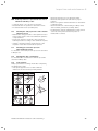
1
2
Fig. 6.4 Flue gas measure points
If the boiler version does not correspond to the local
gas family:
• Perform the gas conversion in accordance with the
gas conversion kit 0020010641.
• Adjust the gas setting as described below
(see sections 6.3.1 to 6.3.3).
The combustion of this boiler has been checked,
adjusted and preset at the factory for operation on the
type of gas defined on the identification plate. No
measurement of the combustion is necessary to set up
the boiler.
• Do not adjust the multifunctional automatic gas valve.
• Ensure
- that the boiler has been installed in accordance with
these instructions,
- the integrity of the flue system and the flue seals,
as described in the flue installation instructions
enclosed with this boiler, and as described below,
- a visual check is carried out on the boiler
combustion circuit and the relevant seals,
- that any defects have been corrected at this stage.
Legend:
1 Flue gas measure point
2 Air measure point
• For checking the system for recirculation use the air
measure point (2).
• Use the flue gas analyser.
• If you detect any CO or CO2 in the fresh air, search
for the flue gas leakage or recirculation.
• Correct the defects.
• Check again as described before, if there is any CO or
CO2 in the fresh air.
• If you cannot correct the defects you must not start
up the boiler.
To further validate the integrity of the flue system and
confirm correct operation of the boiler it is possible to
conduct flue gas and air measurements on this
boiler - for details see section 6.3.1.
Proceed to put the boiler into operation as follows:
Installation and maintenance instructions ecoTEC 0020029173_01
27
6 Start-up
6.3.2 Checking the gas flow rate
The boiler is fitted with a multifunctional automatic gas
valve which ensures that the precise air/gas ratio is
provided under all operating conditions. The gas flow
rate has been set during production and does not
require adjustment. With the front casing fitted check
the gas flow rate of the boiler as follows:
• Start the boiler by activating the test program P.1 as
described in section 9.2.
• In addition, ensure that maximum heat can be
dissipated into the heating system by turning up the
room thermostat.
• Wait at least 5 minutes until the boiler has reached its
operating temperature.
• Ensure that all other gas appliances in the property
are turned off.
• Measure the gas flow rate at the gas meter.
• Check that the gas flow rate is as stated in Table 6.1.
Appliance
ecoTEC VU 656
Maximum net heat input in kW
Gas flow rate
Natural gas in m3/h
65
nom.
+5%
– 10 %
6,9
7,25
6,2
Table 6.1 Gas flow rate
• If the measured gas flow rate lies outside the
tolerance limits specified in Table 6.1, do not operate
the boiler and inform the Vaillant Service Solutions
(0870 6060 777).
If the measured gas flow rate is within the tolerance
limits shown in Table 6.1, then proceed as follows:
• Take the boiler out of operation by
- Pressing the + and i buttons simultaneously and
turn down both thermostat control knobs.
• Record the boiler maximum gas flow rate onto the
Benchmark gas boiler commissioning checklist.
6.3.3 Checking the gas inlet working pressure
• Ensure that the gas inlet working pressure can be
obtained with all other gas appliances in the property
working.
• Remove the front casing from the boiler.
• Close the gas isolation valve of the boiler.
1
2
Fig. 6.5 Measuring the gas inlet working pressure
• Loosen the sealing screw marked “in” (1) on the gas
valve.
• Connect a digital pressure gauge or U-tube
manometer (2).
• Open the gas isolation valve of the boiler.
• Start the boiler by activating the test program P.1 as
described in section 9.2.
• In addition, ensure that maximum heat can be
dissipated into the heating system by turning up the
room thermostat.
• With the boiler operating at full load check that the
gas inlet working pressure at the reference test point
(1) complies with the requirements of Table 6.2.
Natural gas (G20)
Minimum
pressure at reference test
point in mbar
Maximum
pressure at reference test
point in mbar
17
25
Table 6.2 Gas inlet working pressure at the reference test
point
• Should the pressure recorded at the reference test
point in the boiler be lower than indicated (Table 6.2)
check if there is any blockage in the pipework or if the
pipework is undersized.
• If the supply pressure is out of tolerance contact your
Emergency Service Provider.
If the gas inlet working pressure at the reference test
point (1) is not within the permissible range and you
cannot correct the failure, notify the gas supply
company or the Vaillant Service Solutions team and
proceed as follows:
• Take the boiler out of operation by
- Pressing the + and i buttons simultaneously and
turn down both thermostat control knobs.
• Close the gas isolation valve of the boiler.
28
Installation and maintenance instructions ecoTEC 0020029173_01
Start-up 6
• Remove the pressure gauge and re-tighten the sealing
screw (1).
• Turn on gas at the gas isolation valve.
• Make sure that there is no leakage at the sealing
screw.
• Turn off gas at the gas isolation valve.
• Put the front casing back on.
• Turn off electrical supply to the boiler.
• You must not start up the boiler.
If the gas inlet working pressure is within the
permissible range, proceed as follows:
• Take the boiler out of operation by
- Pressing the + and i buttons simultaneously and
turn down both thermostat control knobs.
• Close the gas isolation valve of the boiler.
• Remove the pressure gauge and re-tighten the sealing
screw (1).
• Open the gas isolation valve of the boiler.
• Make sure that there is no leakage at the sealing
screw.
• Put the front casing back on.
• Reset boiler controls for normal operation.
• Record the appliance gas inlet working pressure
(mbar) in the Benchmark gas boiler commissioning
checklist.
6.4
Checking the appliance function
If the installation is complete and the gas setting has
been checked, perform a function check before starting
up the boiler and handing it over to the operator.
• Commission the boiler in accordance with the
instructions in the relevant operating manual.
• Check the tightness of the gas supply line, flue gas
installation, heating installation and hot water pipes.
• Check the flue pipe for proper installation.
• Make absolutely sure that the front casing is properly
closed.
• Check the function of the heating (see Chap. 6.4.1)
and hot water generation (see Chap. 6.4.2)
• Hand over the boiler to the user.
The Vaillant ecoTEC displays status codes to indicate
the operating condition of the boiler. You can perform a
function check based on these status codes by pressing
the "i" button.
Fig. 6.6 Tightness check
6.4.1 Heating
• Switch on the boiler.
• Make sure that heat is being requested.
• Push "i" to activate the status indicator.
As soon as there is a heat demand, the boiler goes
through the status displays "S. 1" to "S. 3", until the
boiler is running properly in normal operation and the
display "S. 4" appears.
Fig. 6.7 Display during heating mode
Installation and maintenance instructions ecoTEC 0020029173_01
29
6 Start-up
6.4.2 Cylinder charging
• Switch on the boiler and the connected hot water
cylinder.
• Make sure that the cylinder thermostat is requesting
heat.
• Push the "i" button.
If the cylinder is correctly charged the boiler runs
through the status displays "S. 20" to "S. 23", until the
boiler is running properly in normal operation and the
display "S. 24" appears.
• Instruct the user about measures taken to ensure the
supply of combustion air and removal of flue gas.
Point out that these measures, particularly, must not
be altered.
• Explain to the operator how to check the water
level/filling pressure of the system and show the
operator how to refill and bleed the heating system
when the need arises.
• Show the user the correct (economical) temperature,
controller and thermostat valve settings.
h Note!
If you connect your controller to a dual-cable
a Caution!
The boiler may only be operated with its casing
eBUS line, specify the highest possible hot
water temperature using the corresponding
rotary knob. Specify the set target temperature
for your cylinder at the controller.
properly and permanently closed! Otherwise,
under unfavourable conditions, it can result in
material damage or even injury or death.
6.6
Vaillant warranty
Vaillant provide a full parts and labour warranty for this
boiler.
The boiler must be installed by a suitably heating
engineer in accordance with the Gas Safety (Installation
and Use) Regulations 1998, and the manufacturer’s
instructions. In the UK ‘CORGI’ registered installers
undertake the work in compliance with safe and
satisfactory standards.
All unvented domestic hot water cylinders must be
installed by a heating engineer to the prevailing building
regulations at the time of installation (G3).
Terms and conditions apply to the warranty, details of
which can be found on the warranty registration card
included with this appliance.
Fig. 6.8 Display in charging mode
6.5
Handing over the control to the owner
Failure to install and commission this appliance in
compliance with the manufacturer’s instructions may
invalidate the warranty (this does not affect the
customer’s statutory rights).
h Note!
Once the installation is complete, please affix
the enclosed sticker (Item No. 835 593)
containing the language used by the operator to
the boiler.
The operator must be instructed in handling and
functions of the ecoTEC boiler.
• Hand over any instruction manuals intended for the
user, as well as the appliance documents for safe
keeping.
• Read through the operating manual with the owner
and answer any questions.
• Draw special attention to the safety instructions which
the owner must follow.
• Make the operator aware of the need for regular
inspection and maintenance of the system.
• Make the operator aware of the need to keep the
manuals in a handy location near the ecoTEC, but not
in or on the boiler.
30
Installation and maintenance instructions ecoTEC 0020029173_01
Adapting the boiler to the heating system 7
7
Adapting the boiler to the heating
system
The ecoTEC boilers are equipped with a Digital
Information and Analysis system (DIA system).
7.1
Selection and setting of parameters
In the diagnosis mode, you can change various
parameters to match the boiler to the heating system.
+
Table 7.1 shows only those diagnosis points where
modifications are possible. All the other diagnosis points
are only required for diagnostics and fault repair
(see Chap. 9).
Using the following description you can select the
relevant parameters:
• Push the "i“ and "+“ buttons simultaneously.
The display shows "d. 0“.
• Scroll to the desired diagnosis number with the "+" or
"–" buttons.
• Push the "i" button.
The display shows the respective diagnosis information.
• If necessary, use the "+" or "–" keys to change the
value (display flashes).
• Save the new value by holding the "i" button pressed
for about 5 seconds until the display stops flashing.
You can finish the diagnosis mode as follows:
• Push the "i“ and "+“ buttons simultaneously or avoid
pressing any buttons for about 4 minutes.
The current heating flow temperature, or installation
pressure (if option is selected), reappears in the display.
7.2
Overview of adjustable system parameters
The following parameters can be set to match the boiler
to the heating system and to suit the customers
requirements:
h Note!
The diagnosis points are divided into two
diagnosis levels.
- Diagnosis level 1 for the operator
- Diagnosis level 2 for the heating engineer
Use the relevant tables; see Chap. 9.1.2.
Note!
If you select diagnosis level 2, all the diagnosis
points are available to you.
Selecting diagnosis level 2:
• Scroll as described above in the 1st diagnosis level to
diagnosis number "d.97".
• Change the displayed value to 17 (password) and save
this value. You are now in the 2nd diagnosis level.
+
Fig. 7.1. Setting the parameters
Installation and maintenance instructions ecoTEC 0020029173_01
31
7 Adapting the boiler to the heating system
Display
Meaning
Adjustable parameters
d. 0
Heating partial load
14 - 65 kW
Factory
setting
46 kW
d. 1
Overrun time of internal pump for
heating mode
2 - 60 min
5 min
d. 2
Maximum blocking time heating at 20°C
flow temperature
Pump speed target value
2 - 60 min
20 min
Target value of internal pump in %:
0 = auto, 1 = 53, 2 = 60, 3 = 70, 4 = 85,
5 = 100
0 = flow, 1 = return
5 (100)
0 = overrun, 1 = run on,
2 = winter, 3 = intermittent
40 to 70 °C
3
1 = circulation pump
2 = ext. Pump
3 = charging pump
4 = vapour extraction hood
5 = ext. solenoid valve
6 = ext. error message
7 = not active
8 = remote control, eBUS (not yet supported)
9 = legionella pump (not active)
2
d.14
d.17
d.18
d.20
d.26
Heating flow/return regulation
changeover
Specification of the pump operating
mode
Maximum setting for cylinder target
value
Additional relay control ecoTEC
0
Switch of relay 1 on the multifunction
module "2 in 7"
1 = circulation pump
2 = ext. Pump
3 = charging pump
4 = vapour extraction hood
5 = ext. solenoid valve
6 = ext. error message
7 = not active
8 = remote control, eBUS (not yet supported)
9 = legionella pump (not active)
1
d.28
Switch of relay 2 on the multifunction
module "2 in 7"
1 = circulation pump
2 = ext. Pump
3 = charging pump
4 = vapour extraction hood
5 = ext. solenoid valve
6 = ext. error message
7 = not active
8 = remote control, eBUS (not yet supported)
9 = legionella pump (not active)
2
d.50
Offset for minimum speed
in rpm/10, adjustment range: 0 to 300
30
d.51
Offset for maximum speed
in rpm/10, adjustment range: -99 to 0
-45
d.71
40 to 85 °C
75 °C
0 - 600 s
80 s
20 - 90 min
45 min
such as heating partial load
65 kW
55 - 85 °C
80 °C
0 to 3000 h and "-"
(300 corresponds to 3000 h, "-" = deactivated)
Setting range: 0 to 99
„-“
d.93
Target value maximum heating flow
temperature
Pump overrun time after cylinder
charging
maximum charging time for hot water
cylinder without independent control
system
Limitation of cylinder charging output
in kW
Limitation of charging temperature
in °C
Maintenance indicator: Number of hours
until the next maintenance
DSN appliance variant setting
d.96
Factory setting
1 = Resetting adjustable parameters to factory
setting
d.97
Activation of the 2nd diagnosis level
Code: 17 for level 2
d.75
d.77
d.78
d.84
do not adjust
65 °C
d.27
d.72
Boiler-specific
setting
47 =
VU 656/4
Table 7.1 Adjustable parameters, levels 1 and 2
32
Installation and maintenance instructions ecoTEC 0020029173_01
Adapting the boiler to the heating system 7
7.2.1 Setting the heating partial load
The output of the boilers is set at 35 kW in the factory.
You can specify a value that corresponds to the kW
output of the boiler under diagnosis point "d. 0“.
7.2.2
Setting of pump overrun and pump operating
mode
The pump overrun time for the heating operation is set
at the factory to a value of 5 minutes. It can be adjusted
through a range of 2 – 60 minutes under diagnosis point
"d. 1“. Under diagnosis point "d.18“, you can set the
overrun behaviour of the pump to a different mode.
Overrun: Once the heating requirement has ended, the
pump runs on for the time specified under "d. 1“.
Run on: The pump is switched on if the rotary knob for
setting the heating flow temperature is not at the
left-hand stop and the heat requirement is enabled by
an external controller.
Intermittent: This pump operating mode is useful for
removing residual heat after charging when the heat
demand is extremely low and large temperature
differences exist between the charging and heating
mode target values. This avoids underheating of the
living spaces. In the event of a heat demand the pump is
switched on every 25 minutes for 5 minutes once the
overrun time has elapsed.
7.2.3 Setting of maximum flow temperature
The maximum flow temperature for the heating is set at
the factory to 75 °C. Under diagnosis point "d.71“ it can
be set to between 40 and 85 °C.
7.2.4 Setting of burner blocking time
To prevent frequent switching on and off of the burner
(energy loss), an electronic restart lockout is activated
for a specific period each time the burner is switched
off. The burner locking time can be modified to suit the
conditions of the heating installation.
The burner blocking time is only activated for the
heating operation.
Hot water operation during a burner blocking time does
not affect the timer. The maximum burner locking time
can be set to a value of between 2 and 60 min under
diagnosis point d.2 (factory setting: 20 min). The
individual effective blocking time is calculated from the
current target flow temperature and the set maximum
burner blocking time.
The timer can be reset or cancelled by pressing the fault
clearance key and also by activating summer mode for a
short time (by briefly turning the nominal flow
potentiometer to the left-hand stop then back to the
starting position). The remaining burner locking time
following a regular shutdown in heating mode can be
called up under diagnosis point "d.67".
Installation and maintenance instructions ecoTEC 0020029173_01
33
7 Adapting the boiler to the heating system
TFlow(target) Set maximum burner blocking time
[°C]
1
5
10
15
20
2.0
5,0
10,0
15,0
25
2.0
4,5
9,2
14,0
30
2.0
4,0
8,5
12,5
35
2.0
4,0
7,5
11,0
40
2.0
3,5
6,5
10,0
45
2.0
3.0
6.0
8,5
50
2.0
3.0
5,0
7,5
55
2.0
2.5
4,5
6.0
60
2.0
2.0
3,5
5,0
65
2.0
1,5
2.5
3,5
70
2.0
1,5
2.0
2.5
75
2.0
1,0
1,0
1,0
[min]
20
20,0
18,5
16,5
15,0
13,0
11,5
9,5
8,0
6.0
4,5
2.5
1,0
25
25,0
23,0
20,5
18,5
16,5
14,0
12,0
10,0
7,5
5,5
3.0
1,0
30
30,0
27,5
25,0
22,0
19,5
17,0
14,0
11,5
9,0
6,5
3,5
1,0
35
35,0
32,0
29,0
25,5
22,5
19,5
16,5
13,5
10.5
7,0
4,0
1,0
40
40,0
36,5
33,0
29,5
26,0
22,5
18,5
15,0
11,5
8,0
4,5
1,0
45
45,0
41,0
37,0
33,0
29,0
25,0
21,0
17,0
13,0
9,0
5,0
1,0
50
50,0
45,0
41,0
36,5
32,0
27,5
23,5
19,0
14,5
10,0
5,5
1,0
55
55,0
50,0
45,0
40,5
35,5
30,5
25,5
20,5
15,5
11,0
6.0
1,0
60
60,0
54,5
49,5
44,0
38,5
33,0
28,0
22,5
17,0
11,5
6,5
1,0
Table 7.2 Effective burner blocking times
The effective burner locking times for each case
depending on the set target flow temperature and the
maximum specified burner locking time can be taken
from Table 7.2.
h Note!
After the set number of hours has elapsed, the
service interval must be entered in the diagnosis mode again.
7.2.5
Determination of maintenance
interval/maintenance display
The ecoTEC electronics incorporate a feature that
enables you to determine the maintenance intervals for
the boiler. This function serves to provide a signal after
a specific, adjustable, number of burner operating hours
that the boiler needs to be maintained.
The service signal SEr and the current flow temperature
are shown alternately in the display of the ecoTEC once
the specified number of burner operating hours has
elapsed. The "maintenance" message appears in the
display of the eBUS controller (accessories).
Heat demand
15 kW
20 kW
25 kW
> 27 kW
Burner operating hours to the next
Number of
inspection/maintenance (dependpersons
ent upon the system type)
2-3
3-4
3-4
4-5
3-4
4-6
3-4
4-6
1.800 h
1.800 h
2.500 h
2.500 h
2.600 h
2.600 h
3.000 h
3.000 h
Table 7.3 Guide values for operating hours
The number of operating hours up to the next
maintenance can be set under the diagnosis point
"d.84". Guide values can be taken from Table 7.3; these
values comply with an approximate operating time of
one year for the appliance.
The operating hours can be set in steps of ten from 0 to
3000 h.
If the symbol "–" is entered at diagnosis point "d.84" instead of a numerical value, the "maintenance display"
function is deactivated.
34
Installation and maintenance instructions ecoTEC 0020029173_01
Inspection and maintenance 8
8
8.1
Inspection and maintenance
Inspection and maintenance intervals
Danger!
Risk of injury and risk of damage to property
due to neglected inspection and maintenance!
Neglected inspection and maintenance works or
not observing the stated inspection and
maintenance intervals can interfere with the
operational safety of the boiler and can result
in damage to property and to persons.
• Point out to the operator that he must
observe the demanded inspection and
maintenance intervals as a minimum.
• Carry out proper regular inspections once a
year.
• Carry out regular maintenance as dictated by
findings during the inspection process.
The frequency of maintenance must not be
longer than every 5 years.
This normally is done by cleaning, adjustment and, if
neces-sary, replacing individual components that are subject
to wear.
You must carry out an annual inspection of the
Vaillant ecoTEC.
It is possible to perform a quick, accurate inspection
without removing components by requesting data from
the DIA system, carrying out the simple visual checks
indicated in Table 8.2 and performing a flue gas
measurement.
The maintenance intervals (at least once every 5 years)
and their scope are determined by the heating engineer
based on the condition of the boiler found during the
inspection.
All inspection and maintenance work should be performed in
the order specified in Table 8.2.
d Danger!
Possible poisoning and burning by escaping hot
flue gases!
It is possible that hot flue gases escape and
could result in poisoning or burning, if the boiler
is operated
- without a completely installed air/flue gas
duct
- with an opened air/flue gas duct
- with internal leakages and an opened front
casing.
• Operate the boiler
- for commissioning
- for testing purposes
- in continuous mode
only with closed front casing and completely
mounted and closed air/flue gas duct.
Danger!
Danger of life and limb due to improper
inspection/maintenance!
Inspections/Maintenance work carried out
improperly can result in leakages and explosion.
• The boiler may only be inspected/maintained
by a competent person.
All service work must be carried out by a competent
person in accordance with the Gas safety, installation
and use regulations. In the UK this is considered to be a
person approved at the time by the Health and Safety
Executive.
In addition BS 6798: 2009 “Specification for installation
and maintenance of gas-fired boilers of rated input not
exceeding 70 kW net” advises that:
- The person carrying out a combustion measurement
must be assessed as competent in the use of a flue
gas analyser and the interpretation of the results.
- The flue gas analyser used must be one meeting the
requirements of BS7927 or BS-EN50379-3 and be
calibrated in accordance with the analyser
manufacturers’ requirements.
- Competence can be demonstrated by satisfactory
completion of the relevant ACS standard assessment,
which covers the use of electronic portable flue gas
analysers’ in accordance with BS 7967, parts 1 to 4.
- The flue gas analyser is set to the correct fuel setting.
8.1.1
We recommend the conclusion of an inspection and
maintenance contract with an approved company or installer.
The inspection serves to determine the actual condition of
the respective boiler and compare it with the specified
condition. This is done by measuring, checking and observing.
Maintenance is required in order to eliminate any deviations
of the actual condition from the specified condition.
- The appliance has been installed in accordance with
the relevant installation instructions.
- The integrity of the flue gas installation and flue seals
is in accordance with the relevant flue installation
instructions enclosed.
- Visual, the integrity of the boiler combustion circuit
and relevant seals.
Installation and maintenance instructions ecoTEC 0020029173_01
General inspection and maintenance
instructions
To ensure the faultless operation, long term availability
of all functions and long working life of your Vaillant
boiler and to prevent modifications to the approved
series status only genuine Vaillant spare parts must be
used when carrying out inspection, maintenance and
repair work.
For an overview of the available original Vaillant spare
parts, contact the Vaillant sales office on
01634 292310.
During any inspection and maintenance or after change
of parts of the combustion circuit, the following must be
checked:
35
8 Inspection and maintenance
- The gas inlet working pressure at maximum rate as
described in section 6.3.3.
- The gas flow rates as described in section 6.3.2.
- Correctness of electrical, water and gas connections.
- Correctness of the water pressure.
- The condition of the whole system, in particular the
condition of radiator valves, evidence of leakage from
the heating system and dripping taps.
• Correct any faults before proceeding.
8.1.2
Safety instructions
Danger!
Danger of life and limb by electric shock!
The supply terminals of the boiler are under
mains voltage even if the boiler main switch is
off.
• Do not touch the supply terminals.
• Protect the electronic box from any water or
spray.
• Before working on the boiler, turn off the
power and secure against restart.
• Bleeding the heating installation (see section 6.2,
Filling the system).
• Open the gas isolation valve.
• Check the boiler for gas and water leaks.
• If necessary, refill and re-bleed the heating
installation.
• Replace the front casing to the boiler.
• Carry out a functional check of the boiler
(see section 6.4).
• Always check earth continuity, polarity and resistance
to earth with a multimeter after any service work and
after replacing any electrical component.
8.1.3
Checking the CO2 concentration
Note
Checking/adjustment of the CO2 concentration
is required in the following instances:
- replacement of gas valve,
- conversion to or from Natural Gas
- or if an incorrect combustion is suspected.
1
Note
If it is necessary to keep the electricity to the
boiler switched on for certain inspection and
maintenance, this is indicated in the description
of the maintenance task.
Always perform the following steps prior to inspection
or maintenance work:
• Switch off the main switch.
• Disconnect the boiler from the power mains by
- disconnecting the mains plug or
- de-energising the boiler via an isolating device with a
contact opening of at least 3 mm (e. g. fuses or
power switches).
• Further check for electrical isolation of the appliance
by use of a test meter.
• Close the gas isolation valve.
• Close the service valves in the heating flow and
return.
• Remove the front casing from the boiler.
• When removing any water carrying components
ensure that water is kept away from all electrical
components.
Always perform the following steps after performing
any inspection or maintenance work:
• Always use new seals and O-rings when parts are
replaced.
• Open the service valves in the heating flow and
return.
• Reconnect the boiler to the power mains.
• Switch the main switch on.
• Fill the heating circuit of the boiler to a pressure of
between 1.0 and 2.0 bar if required.
36
4
2
3
Fig. 8.1 Measuring the CO2 concentration, specifying the air
ratio (gas setting)
Legend:
1 Flue gas analysis point
2 Screw
3 Air intake pipe
4 Main throttle
Note
The boiler is fitted with a flue gas analysis
point (1). A suitable flue gas analyser can be
connected to this point to establish the
combustion performance of the boiler.
Installation and maintenance instructions ecoTEC 0020029173_01
Inspection and maintenance 8
• Remove the front casing.
• Start the testing program P.1.
• Wait at least 5 minutes until the boiler reaches its
operating temperature.
• Measure the CO2 concentration at the flue gas
analysis point (1). Compare the measured value with
the corresponding value in Table 8.1.
• If all these points are as required, proceed as
described in section 8.1.5.
• If one of the flue gas values is greater than the
acceptable values in Table 8.1, then proceed as
described in the following section 8.1.4.
8.1.4
Adjusting the CO2 concentration (or the air
ratio)
d
Danger!
Increased risk of poisoning due to incorrect
settings!
Incorrect setting may increase the risk of
poisoning.
• If one of the flue gas values is greater than
the acceptable values in Table 8.1 then check
- the integrity of the complete flue gas
installation
- the integrity of the combustion circuit seals
- the gas inlet working pressure
- the gas flow rate.
If the flue gas value needs to be adjusted,
• unfasten the screw (Fig. 8.1, 2) and
• fold the air intake pipe (Fig. 8.1, 3) forwards through
90°. Do not remove the air intake pipe.
• Specify the required flue gas value if necessary (value
with front casing of boiler removed, see Table 8.1) by
turning the screw of the main throttle (Fig. 8.1, 4)
• Push the „i“ button to deactivate the full load mode.
The full load mode is also deactivated if no button is
pushed for 15 minutes.
• The adjusting screw shall be sealed after the
adjustment.
• Re-secure the air intake pipe with the screw (2).
• Put the front casing back on.
Settings
Natural gas (H)
Tolerance
Unit
CO2 after 5 minutes full
load mode with
boiler front casing closed
9.0
1.0
Vol.–%
CO2 after 5 minutes full
load mode with boiler front casing
removed
8.8
1.0
Vol.–%
Set for Wobbe index Ws
CO value with full load
CO/CO2
15
< 250
kWh/m3
ppm
< 0,0031
Table 8.1 Factory gas setting
Danger!
d Risk
to life due to poisoning!
CO is an extremely toxic gas. Risk to life due to
excessive CO concentrations.
• If you are not able to adjust the boiler
correctly and the flue gas values remain
higher than allowed in Table 8.1, call the
Vaillant Service Solutions.
• Do not start up the boiler!
h Note
Use a 4 mm hexagon socket spanner to turn
the screw.
• Turn to the left: higher CO2 concentration,
• Turn to the right: lower CO2 concentration.
h Note
Natural gas: Only perform the adjustment in
increments of 1/8 turn and wait approximately
1 minute after each adjustment until the value
stabilises.
Liquid gas: Only perform the adjustment in very
small increments (approximately 1/16 turns),
and wait approximately 1 minute after each
adjustment until the value stabilises.
• After performing the adjustments, fold the air intake
pipe back up.
• Check the CO2 concentration once again.
• If necessary, repeat the setting process.
Installation and maintenance instructions ecoTEC 0020029173_01
37
8 Inspection and maintenance
8.1.5
.
Inspection and maintenance work steps
Column 2
Maintenance
Column 1
must be carried
Inspection must
out at regular
be carried out
intervals – but
each year
no longer than
5 years
No. Activity
1
Check the air flue gas installation for leaks and for proper fixation and ensure it is not blocked
or damaged and is fitted correctly, complying with the relevant installation instructions.
x
x
2
Carry out a general inspection of the boiler for dirt and dust and clean as necessary.
x
x
3
Visually inspect the complete heat engine for its general condition and for signs of corrosion,
sooting or other forms of damage. If damage is evident proceed to column 2.
x
x
4
Measure the gas flow rate during operation with maximum load (section 6.3.2). If the gas flow
rate complies to the Table 6.1 continue with column 1, if not proceed to column 2.
x
x
x
x
5
6
Check the gas inlet working pressure (section 6.3.3) operation with maximum load. If the gas
inlet working pressure complies to the Table 6.2 continue with column 1, if not proceed to
column 2.
Check combustion by measuring CO, CO2 and CO/CO2. If the values are outside the
tolerances of Table 8.1 proceed to maintenance column 2. You must not proceed with the
maintenance if a new burner door seal kit is not available.
x
7
Isolate the boiler from the power mains. Check whether the electrical plug connections and
the other electrical connections are fitted tightly and correct them if necessary.
8
Close the gas isolation valve and the service valves.
x
9
Dump the pressure in the boiler on the water side (observe pressure gauge) and check the
charge pressure of the expansion vessel. Top up if necessary.
x
x
10 Remove the compact thermal module.
11
x
x
Check the integrity of all combustion circuit seals, especially the burner door seal. If there are
any damages repair them before proceeding.
x
12 Clean the heat exchanger.
x
13
x
Check whether the burner is dirty and clean it if necessary.
14 Check the condensate siphon in the boiler, clean and fill if necessary.
x
x
15 Check the condensate ducts in the boiler and clean if necessary.
x
x
16 Clean the air separation system.
x
17
x
Install the compact thermal module. Caution: Use new seals and nuts!
Open the service valves and fill up the boiler/appliance to approximately 1.0 - 2.0 bar
(depending on the static height of the system). Start the bleeding program P.0.
Open the gas isolation valve, reconnect the boiler with the power mains and switch on the
19
boiler.
Perform a test operation of the boiler and heating installation, including water heating and
20
bleed again if necessary.
18
21 Check visually the ignition and burner performance.
22
Check the boiler for leaks of any kind (gas, flue gas, water, condensate) and rectify as
necessary.
x
x
x
x
x
x
x
x
x
If you had problems with the CO, CO2, CO/CO2-values in Step 6 before the maintenance, check
23 them again now (see Table 8.1). If they are outside of the tolerances of Table 8.1 make an
adjustment, see section 8.1.4.
24 Complete the gas commission checklist (benchmark book).
x
x
x
Table 8.2 Inspection and maintenance steps
38
Installation and maintenance instructions ecoTEC 0020029173_01
Inspection and maintenance 8
8.2
Filling/draining the boiler and heating
installation
1
2
8.2.1 Filling the boiler and the heating installation
A description of how to fill the boiler and heating
installation is provided in Chap. 6.2.
3
8.2.2 Draining of the boiler
• Close the service valves of the boiler.
• Open the drain valve on the return line connection.
• To drain the boiler completely, open:
- the automatic air vent on the air separator,
- the bleed nipple on the flow line connection.
8.2.3 Draining the entire system
• Attach a hose to the draining device on the system.
• Bring the open end of the hose to an appropriate
drain point.
• Make sure that the service valves of the boiler are
open.
• Open the drain cock.
• Open the bleed valves on the radiators.
Start from the highest radiator and then work from
the top to the bottom.
• Once the water has drained off, close the automatic
air vents of the radiator and the drain cock.
8.3
Maintenance of the compact thermal module
8.3.1 Dismounting the compact thermal module
The compact thermal module consists of the
variable-speed fan, the gas/air combination valve, the
gas feed (mixture pipe) to the fan premix burner and the
premix burner itself. These four individual parts form the
compact thermal module component.
H Danger!
Danger of burning or scalding!
There is danger of being burned or scalded at
the compact thermal module and at all
water-carrying components. Only carry out
work on these components once they have
cooled down.
To dismount the compact thermal module proceed as
follows:
• Turn off the boiler by the main switch.
• Isolate the boiler from the electrical mains.
• Cut off the gas supply to the boiler.
• Remove the front casing of the boiler.
• Swing off the electronic box.
Installation and maintenance instructions ecoTEC 0020029173_01
4
5
6
7
10 9
8
Fig. 8.2 Dismounting compact thermal module
• Unfasten the fixing screw on the air intake
pipe (3).
• Swing the air intake pipe (2) forwards.
• Remove the air intake pipe from the intake port.
• Disconnect the two plugs for the ignition and
grounding connections from the ignition electrode (5).
• Disconnect the gas supply (9) on the bottom of the
gas valve.
• Disconnect the cable (7) from the coupling plug in the
feed to the fan motor, the PWM signal cable on the
bottom of the fan (8) and the cable to the gas valve
(10).
• Undo the six nuts (4).
a Caution!
Damage to gas supply!
Under no circumstance may the compact
thermal module be suspended from the flexible
corrugated gas pipe.
• Pull off the entire compact thermal module (6) from
the heat exchanger (1).
• After dismounting the burner and heat exchanger,
check for damage and soiling – clean the components
if necessary as described below.
39
8 Inspection and maintenance
H Danger!
Danger of combustion and damage due to
escaping hot flue gases!
The silicone seal and the silicate cord on the
compact thermal module (No. 180904) must be
replaced at every maintenance operation. The
insulating layer on the burner door
(No. 180913) must not exhibit any signs of
damage; otherwise it must also be replaced
(see Chap. 8.3.4).
8.3.2
Cleaning the heat exchanger
8.3.3 Checking the burner
The burner is maintenance-free and needs no cleaning.
• Check the surface of the burner for damage, replace
the burner if necessary.
• After checking/repairing the burner install the
compact thermal module as described in Chap. 8.3.4.
8.3.4 Installing the compact thermal module
1
2
a Caution!
Danger of short-circuiting and irrepairable
damage to the PCB and fan!
Protect the downfolded electronic box and also
the fan against splash water.
1
1
2
3
2
Fig. 8.4 Replacing the seals and the insulating layer on the
burner door
H Danger!
Danger of combustion and damage due to
Fig. 8.3 Cleaning the heat exchanger
escaping hot flue gases!
The silicone seal and the silicate cord on the
compact thermal module (No. 180904) must be
replaced at every maintenance operation. The
insulating layer on the burner door
(No. 180913) must not exhibit any signs of
damage; otherwise it must also be replaced.
• Dismount the compact thermal module as described
under 8.3.1.
• Clean the heating coil (2) of the heat exchanger (3)
using commercially-available essence of vinegar. Flush
with water. The water flows out of the heat exchanger
through the condensate siphon. You can also clean
the condensate trap via the opening (4).
• Allow the cleaning agent to take effect for
approximately 20 minutes then rinse off the loose
dirt. To clean the coils you can use a brush with
synthetic bristles, but no aids with metallic or similar
materials. Avoid getting large amounts of water
directly on the insulating mat at the back wall of the
heat exchanger. Otherwise the insulating mat can be
damaged.
40
Installation and maintenance instructions ecoTEC 0020029173_01
Inspection and maintenance 8
1
2
3
4
5
6
1
Fig. 8.6 Checking for gas tightness
7
a Caution!
Open the gas feed and check the gas tightness
10 9
of the boiler with leak detector spray. Check
the screwed connection (1) particularly
carefully.
8
Fig. 8.5 Installing the compact thermal module
• Insert the compact thermal module (6) into the heat
exchanger (1).
• Tighten the six nuts (4) including the retainer for the
air intake pipe crosswise until the burner door is
uniformly seated on the contact surfaces.
• Make sure the blue sealing ring in the air intake pipe is
positioned correctly in the seal face.
• Insert the air intake pipe (2) onto the intake stubs and
fasten the pipe with the retaining screw (3).
• Plug on the ignition wire and the ground connection.
• Plug in the cable (7) to the coupling plug in the feed
to the fan motor, the PWM signal cable on the bottom
of the fan (8) and the cable to the gas valve (10).
• Connect the gas supply (9) with a new seal to the gas
valve. Use the spanner flat at the flexible gas line to
hold up the gas valves.
8.4
Cleaning the condensate ducts and the
condensate siphon
d Danger!
If the boiler is operated whith empty
condensate siphon, there is risk of poisoning
from escaping flue gases.
Therefore, fill up the siphon again after each
cleaning session.
1
2
Fig. 8.7 Cleaning the condensate ducts
For the purpose of cleaning the condensate ducts, the
condensate hose (1) of the heat exchanger and the
complete condensate siphon (2) can be dismounted.
Installation and maintenance instructions ecoTEC 0020029173_01
41
8 Inspection and maintenance
After that, both can be cleaned in the dismounted state.
Take note also of the accompanying installation manual
for the siphon cartridge.
8.5
Cleaning the air separation system
H Danger!
Danger of burning or scalding!
All water-carrying components present a
danger of injury and scalding. Only carry out
work on these components if they have cooled
down.
• Drain the boiler (see Chap. 8.2.2).
1
1
2
3
4
Fig. 8.8 Cleaning the condensate siphon
•
•
•
•
•
Dismount the siphon cartridge (1) below the boiler.
Clean the siphon cartridge.
Remove the clamp below the heat exchanger.
Pull off the connecting bracket.
Dismount the siphon and the corrugated pipe (pay
attention to the position of the latching tabs).
• Clean the components.
a Caution!
Risk of damage!
Fig. 8.9 Removing the air separator
• Unfasten the 1 1/2 " nut (4) on the lower outlet.
• Unfasten the 1/4 " cap nut (1) on the upper inlet
(unfasten the cable harness).
• Push the casing (3) to the front.
• Pull out the complete assembly to the front.
Dismount the pipe (2) only if necessary.
Take care that no water splashes onto other
components!
After cleaning, refit all the components in the
condensate duct (see the siphon installation manuals).
Be absolutely sure to fill the siphon cartridge with
water. Insert new seals at all points and check the
condensate duct for leaks.
4
5
6
Fig. 8.10 Cleaning the filter
•
•
•
•
Unscrew the brass cover (4) of the steel casing (6).
Pull out the filter (5) upwards.
Rinse out the air separator with hot water.
Clean the filter with hot water or replace it with a new
one.
• Insert the filter into the air separator.
42
Installation and maintenance instructions ecoTEC 0020029173_01
Inspection and maintenance 8
a Caution!
All O-rings must be replaced with new ones as
otherwise leaks may occur!
• Screw the brass cover onto the air separator.
• Reassemble the air separator in the reverse order.
• Fill and bleed the boiler (see Chap. 6.2)
8.6
Checking the charge pressure of the external
expansion vessel
• Measure the charge pressure of the expansion vessel
at the testing nozzle of the vessel when the aplliance
is depressurised.
• Fill the gas cushion as required to the prescribed
nominal pressure according to the identification plate.
• If water is discharged at the testing nozzle of the
expansion vessel the vessel must be replaced.
• Check the appliance for gas and water leaks.
• Check the flue system for leaks and for proper
fixation.
• Check over-ignition and that the flame on the burner
is burning evenly.
• Check the function of the heating (see Chap. 6.4.1)
and hot water generation (see Chap. 6.4.2)
• Document the inspection/maintenance tasks carried
out in the form provided in the inspection or
maintenance contract.
8.7
Checking gas connection pressure
(inlet working pressure)
To check the connection pressure proceed as described
in Chap. 6.3.3.
8.8
Checking the CO2 concentration
To check the CO2 concentration follow the procedure
described in Chap. 8.1.3.
8.9
Test operation
Always perform the following checks after completing
any maintenance task:
• Start up the appliance in accordance with the
instructions in the relevant operating manual.
Fig. 8.11 Tightness check
Installation and maintenance instructions ecoTEC 0020029173_01
43
9 Troubleshooting
9
Troubleshooting
h Note!
Whenever possible, please quote the fault code
displayed (F.xx) and the status of the boiler
(S.xx) when contacting the Vaillant customer
service or your Vaillant service partner.
9.1
Diagnostics
9.1.1
Status codes
The status codes that you can see on the display
provides information about the current operating
condition of the boiler.
The display of the status codes can be viewed as
follows:
Display Meaning
Heating
S.0
S.1
S.2
S.3
S.4
S.5
S.6
S.7
S.8
mode
Heating mode no heat demand
Heating mode fan start-up
Heating mode pump pre-run
Heating mode ignition
Heating mode burner on
Heating mode pump/fan overrun
Heating mode fan overrun
Heating mode pump overrun
Heating remaining off-time xx min
Domestic hot water mode (DHW)
S.20
S.21
S.22
S.23
S.24
S.25
S.26
S.27
S.28
Hot water requirement
Fan start-up
Pump pre-run
Ignition
Burner on
Pump/fan overrun
Fan overrun
Mode pump overrun
Burner off-period
Other:
S.30
S.31
S.32
S.34
S.36
S.39
S.41
Fig. 9.1 Display of status codes
• Push the "i" button.
The status code appears in the display, e.g. S.4 for
"Burner operation, heating".
S.42
S.53
S.54
The display of the status codes can be ended as follows:
• Push the "i" button
or
• Do not push any buttons for about 4 minutes.
Depending on the settings, the current flow
temperature or current water pressure of the heating
installation reappears in the display.
S.59
S.85
S.96
S.97
S.98
Heating mode blocked by room thermostat
(terminal 3-4 open)
Summer mode active or no heat demand from eBUS
controller
Heat exchanger antifreeze active, as fan speed variation is too high. Appliance is within the waiting time of
the operation block function
Antifrost mode active
Reference setting of continuous controller 7-8-9 or
e-BUS controller is < 20°C and blocks the heating mode
Contact thermostat activated
Water pressure > 2.8 bar
Exhaust gas diverter return signal blocks burner
operation (only in connection with accessories) or
condensate pump faulty, heat demand is blocked
Unit is observing the waiting time for the modulation
block/operation block function due to a water shortage
(flow-return difference too large)
Unit is observing the waiting period of the operation
block function due to a water shortage (temperature
gradient)
Waiting time: minimum quantity of circulation water not
achieved
Check quantity of circulation water
Return sensor test running, heating demands are
blocked
Water pressure sensor test running, heating demands
are blocked
Self-test flow/return NTC
Table 9.1 Status codes
44
Installation and maintenance instructions ecoTEC 0020029173_01
Troubleshooting 9
9.1.2 Diagnosis codes
In the diagnosis mode, you can change certain
parameters or display more information.
The diagnosis information is divided into two diagnosis
levels. The 2nd diagnosis level can be reached only after
entering a password.
a Caution!
The access to the 2
nd
diagnosis level may only
be used by a qualified heating engineer.
1st diagnosis level
• Push the "i“ and "+“ buttons simultaneously.
The display shows "d.0“.
• Scroll to the desired diagnosis number on the 1st
diagnosis level with the "+" or "–" buttons (see
Table 9.2).
• Push the "i" button
The display shows the relevant diagnosis information.
• If necessary, use the "+" or "–" keys to change the
value (display flashes).
• Save the new value by holding the "i" button pressed
for about 5 seconds until the display stops flashing.
You can finish the diagnosis mode as follows:
• Push the "i“ and "+“ buttons simultaneously or
• Do not push any buttons for about 4 minutes.
The current heating flow temperature or the current
water pressure of the heating installation reappears in
the display.
Installation and maintenance instructions ecoTEC 0020029173_01
45
9 Troubleshooting
Display Meaning
Display value/adjustable value
d.0
Heating partial load
d.1
d.2
Pump overrun for heating mode
Maximum blocking time heating at 20°C flow temperature
Measured value of cylinder sensor
Target value of flow temperature (or target value of
return)
Adjustable heating partial load in kW (factory setting: approx. 70%
of maximum output)
2 - 60 minutes (factory setting: 5)
2 - 60 minutes (factory setting: 20)
d.4
d.5
in °C
in °C, maximum of the value set in d.71, limited by an eBUS controller
if connected)
d.7
d.8
Set hot water temperature
Room thermostat at terminals 3-4
40 to 65 °C (maximum temperature can be adjusted at d.20)
0 = Room thermostat open (no heat request)
1 = Room thermostat closed (heat request)
d.9
Set target flow temperature at terminal 7-8-9
d.10
d.11
d.12
d.13
d.15
d.22
d.23
d.24
d.25
Status of internal pump
Status external heating pump
Status of cylinder primary pump
Status of hot water circulation pump
Pump speed actual value
Hot water requirement via C1/C2, internal hot water
control system
Summer/winter operation (heating on/off)
not relevant
Hot water generation enabled by eBUS controller
in °C, minimum off, target value of ext. eBus and target value of
terminal 7
1 = on, 0 = off
1 to 100 = on, 0 = off
1 to 100 = on, 0 = off
1 to 100 = on, 0 = off
Actual value internal pump in %
1 = on, 0 = off
d.29
Actual value, sensor circulation water quantity
d.30
Control signal for the gas valve
1 = on, 0 = off
d.33
Fan speed target value
in rpm/10
d.34
d.35
Fan speed actual value
not relevant
in rpm/10
Not relevant
d.40
forward flow temperature
actual value in °C
d.41
Return flow temperature
actual value in °C
d.44
digitalised ionisation voltage
Display range 0 to 102, >80 no flame, <40 good flame display
d.47
Actual value in °C
d.76
External temperature (with weather-controlled Vaillant
controller)
Boiler variant (display): Device specific number (DSN)
d.90
Digital regulator status
1 = detected, 0 = not detected (eBUS Address <=10)
d.91
DCF status with external sensor connected
0 = no reception, 1 = reception, 2 = synchronised, 3 = valid
d.97
Activation of the 2nd diagnosis level
Code: 17 for level 2
1 = heating on (winter mode), 0 = heating off (summer mode)
not relevant
1 = yes, 0 = no
Actual value in m3/h
47
Table 9.2 Diagnosis codes in the 1st diagnosis level
2nd diagnosis level
• Scroll as described above in the 1st diagnosis level to
diagnosis number d.97.
• Change the displayed value to 17 (password) and save
this value.
h Note!
If you push the buttons "i" and "+" within
4 minutes of leaving the 2nd diagnosis level,
you can directly access the 2nd diagnosis level
without re-entering the password.
You are now in the 2nd diagnosis level in which all
information from the 1st (see Table 9.2) and the 2nd
(see Table 9.3) is displayed.
Scroll and change values and exit diagnosis mode as
described in the 1st diagnosis level.
46
Installation and maintenance instructions ecoTEC 0020029173_01
Troubleshooting 9
Display
Meaning
Display value/adjustable value
d.14
Pump speed target value
d.17
Heating flow/return regulation changeover
Target value of internal pump in % Possible settings:
0 = auto (factory setting)
1 = 53
2 = 60
3 = 70
4 = 85
5 = 100 (factory setting)
0 = flow, 1 = return (factory setting: 0)
d.18
Specifying the pump operating mode
d.20
Maximum setting for cylinder target value
d.26
Additional relay control ecoTEC
1 = circulator
2 = ext. pump (factory setting)
3 = cylinder charge pump
4 = extractor hood
5 = ext. solenoid valve
6 = ext. fault message
7 = not active
8 = remote control eBUS (not yet supported)
9 = legionella pump (not active)
d.27
Switch of relay 1 on the multifunction module "2 in 7"
1 = circulator (factory setting)
2 = ext. pump
3 = cylinder charge pump
4 = extractor hood
5 = ext. solenoid valve
6 = ext. fault message
7 = not active
8 = remote control eBUS (not yet supported)
9 = legionella pump (not active)
d.28
Switch of relay 2 on the multifunction module "2 in 7"
d.50
Offset for minimum speed
1 = circulator
2 = ext. pump (factory setting)
3 = cylinder charge pump
4 = extractor hood
5 = ext. solenoid valve
6 = ext. fault message
7 = not active
8 = remote control eBUS (not yet supported)
9 = legionella pump (not active)
in rpm/10, adjustment range: 0 to 300 (factory setting 30)
d.51
Offset for maximum speed
in rpm/10, adjustment range: -99 to 0 (factory setting -45)
d.60
Number of temperature limiter shutdowns
Number
d.61
Number of faults in automatic combustion system
Number of successful ignitions in the last attempt
d.64
Average ignition time
in seconds
d.65
Maximum ignition time
in seconds
d.67
Remaining burner locking time
in minutes
d.68
Unsuccessful ignitions at 1st attempt
Number
d.69
Unsuccessful ignitions at 2nd attempt
Number
d.70
not relevant
Not relevant
d.71
Target value maximum heating flow temperature
Adjustment range in °C 40 to 85 (factory setting: 75)
d.72
Pump overrun time after cylinder charging
d.75
d.77
0 = overrun
1 = run on
2= winter
3 = intermittent (factory setting)
40 to 70°C (factory setting: 65°C)
Setting range in seconds: 0, 10, 20 to 600
(factory setting: 80 s)
Maximum charging time for hot water cylinder without Adjustment range in min: 20 - 90 (factory setting: 45 min)
independent control system
Limitation of cylinder charging output in kW
Adjustment range in kW: depending on boiler
(factory setting: maximum output)
d.78
Limitation of charging temperature in °C
55 to 85°C (factory setting: 80 °C)
d.80
Operating hours heating
in h1)
Table 9.3 Diagnosis codes for diagnosis level 2 (continued on
next page)
Installation and maintenance instructions ecoTEC 0020029173_01
47
9 Troubleshooting
Display
Meaning
Display value/adjustable value
d.81
Operating hours hot water generation
in h1)
d.82
Burner start-ups in heating mode
Number/1001) (3 equals 300)
d.83
Burner start-ups in hot water mode
Number/1001) (3 equals 300)
d.84
d.93
Maintenance indicator: Number of hours until the next
maintenance
DSN appliance variant setting
Setting range: 0 to 3000h and "-“ for deactivated
Factory setting: "-“ (300 corresponds to 3000h)
Setting range: 0 to 99
d.96
Factory setting
1 = yes (Resetting adjustable parameters to factory setting)
2 = no
1) In the diagnosis codes 80 to 83 5 digit figure values are stored. When selecting e.g. d.80 only the first two digits of the figure value
are displayed (e.g.10). By pressing the "i“ key, the display switches over to the last three figures (e.g. 947). The operating hours
counter of the heating in this case would be 10947 h. Pressing the "i" again causes the display to switch back to the diagnosis point
that was called up.
Table 9.3 Diagnosis codes at diagnosis level 2 (continued)
9.1.3 Fault codes
The fault codes displace all other displays when errors
occur. Errors are displayed as "F ...", e.g. "F.10"
(see Table 9.4).
If several errors occur simultaneously, each fault code is
displayed for approximately two seconds on an
alternating basis.
Once you have repaired the error push the fault
clearance key to restart the boiler.
If the error cannot be repaired and reoccurs despite
having carried out several fault clearance attempts,
please contact your factory customer service.
9.1.4 Fault memory
The last ten errors which occurred are saved in the
appliance fault memory.
• Push the "i“ and „-“ buttons simultaneously.
• Scroll back in the error memory with the "+" button.
You can exit the fault memory display as follows:
• Push the "i" button
or
• Do not push any buttons for about 4 minutes.
Depending on the settings, the current flow temperature
or current filling pressure of the heating installation
reappears in the display.
48
Installation and maintenance instructions ecoTEC 0020029173_01
Troubleshooting 9
Code
F. 0
Meaning
Interruption, flow temperature sensor
Cause
NTC plug not plugged in or has come loose, multiple plug on
electronics not plugged in correctly, interruption in cable harness,
NTC defective
NTC plug not plugged in or has come loose, multiple plug on
electronics not plugged in correctly, interruption in cable harness,
NTC defective
F. 1
Interruption, return temperature sensor
F.10
F.11
Short circuit flow sensor
Short circuit, return sensor
Short to ground/short circuit in cable harness, NTC defective
Short to ground/short circuit in cable harness, NTC defective
F.13
Short circuit cylinder sensor
F.20
Safety switch-off, temperature limiter
F.22
Safety switch-off, water shortage
Short to ground/short circuit in cable harness, moisture in plug,
NTC defective
Incorrect earth connection between cable harness and boiler, flow
or return NTC defective (loose connection), black discharge via
ignition cable, ignition plug or ignition electrode
No or insufficient water in boiler, cable for pump, water pressure
sensor or volume flow sensor loose/not plugged in/defective, pump
blocked or defective, pump output too low, non-return valves
blocked/incorrectly installed, minimum quantity of circulation
water not reached, flow sensor defective
F.23
Safety switch-off: temperature difference too great
F.24
Safety switch-off: temperature increase too fast
F.25
Safety switch-off: Flue gas temperature too high
Break in plug connection for optional flue gas safety thermostat,
break in cable harness
F.27
Safety switch-off: flame simulation
Moisture on electronics, electronics (flame monitor) defective, gas
solenoid valve leaking
F.28
Failure during start-up: ignition unsuccessful
gas meter defective, gas pressure monitor has been triggered, air
in gas, gas flow pressure too low,
Thermal isolator device (TAE) has been triggered, condensate duct
blocked, incorrect gas throttle, error at gas valve, multiple plug on
electronics incorrectly plugged in, break in cable harness, ignition
system (ignition transformer, ignition cable, ignition plug, ignition
electrode) defective, ionisation current interrupted (cable,
electrode), incorrect earthing of boiler, electronics defective
F.29
Failure during operation: re-ignition unsuccessful
Gas feed interrupted from time to time, flue gas recirculation,
condensate duct blocked, faulty earthing of boiler
F.32
Error, fan
Plug at fan not correctly plugged in, multiple plug on electronics
not correctly plugged in, break in cable harness, fan blocked, Hall
sensor defective, electronics defective
F.49
Error, eBUS
F.61
Error, fuel valve control
F.62
Error, fuel valve switch-off delay
F.63
EEPROM error
Short-circuit on eBUS input, eBUS overload or two power supplies
with different polarities on the eBUS
short circuit/short to ground in cable harness for gas valve, gas
valve defective (coils shorted to ground), electronics defective
delayed shutdown of gas valve, delayed extinguishing of flame
signal, gas valve leaking, electronics defective
Electronics defective
F.64
Error, electronics/sensor
F.65
Error, temperature of electronics
Flow or return NTC short circuited, electronics defective recirculation
Electronics too hot due to external effect, electronics defective
F.67
Error, electronics/flame
Implausible flame signal, electronics defective
F.70
Invalid boiler ID
F.71
Error, flow temperature sensor
Spare part case: Display and electronics changed at the same time
boiler variant not re-set
Flow temperature sensor signalling constant value -> flow
temperature sensor defective
Pump blocked, insufficient pump output, air in appliance, system
pressure too low, flow and return NTC interchanged
Pump blocked, poor pump performance, air in boiler, installation
pressure too low, non-return valves blocked/incorrectly installed,
flow and return NTC mixed up
Table 9.4 Fault codes (continued on next page)
Installation and maintenance instructions ecoTEC 0020029173_01
49
9 Troubleshooting
Code
F.72
Meaning
Flow and/or return temperature sensor fault
Cause
Temperature difference between flow temperature sensor and
return temperature sensor too great -> flow and/or return
temperature sensor defective
Interruption/short-circuit of water pressure sensor, interruption/
short-circuit to GND in supply line to water pressure sensor
F.73
Error in water pressure sensor
F.74
Water pressure sensor signal outside correct range
(too high)
Line to water pressure sensor has short-circuited at 5V/24V
or internal error in water pressure sensor
F.75
Error, pump water shortage
Water pressure sensor and/or pump defective, air in heating
system, too little water in boiler; check adjustable bypass, connect
external expansion vessel to return
F.77
Error, flue gas flap/condensate pump
condensate pump defective, cable connection; no checkback signal
from flue gas flap (bridge) of "2 in 7" multifunction module, flue
gas flap has triggered
con
No communication with the printed circuit board
Communication error between display and PCB in the electronic
box
Table 9.4 Fault codes (continued)
9.2
Test programs
Special functions can be triggered in the boilers by
activating various test programs.
The test programs P.0 to P.6 are started as follows:
• Push the "+" button and hold it down.
• Push the "Fault clearance key" once or switch the
main switch off and on again.
After approximately 5 seconds, P.0 appears in the display. You can now release the "+" button.
• Push the "+" key to start counting the test
programme number upwards.
• Push the "i“ to operate the boiler now and to start the
test programme.
• Push "i“ and "+“ simultaneously to exit the test
programs. You can also exit the test programs by not
pushing any button for 15 minutes.
Display
P. 0 1)
Meaning
Bleeding test program
The heating circuit and the hot water circuit are bled
via the automatic automatic air vent (the cap of the
automatic automatic air vent must be released).
1 x "i" button: Start bleeding heating circuit
(display view: HP)
2 x "i" button: Start bleeding charging circuit
(display view: SP)
3 x "i" button: Exit bleeding program
The heating pump is cyclically actuated
Note: The bleeding program takes about 6.5 minutes
to complete.
Test program, maximum load:
The boiler is operated at full load following successful
ignition and calibration.
P.1
P.2
Test program, minimum load:
The boiler is operated at minimum load following
successful ignition and calibration.
P.5
Test program, safety thermostat:
The burner is switched on at maximum output and the
temperature control is switched off so that the boiler
produces heat, bypassing a regular shutdown, until the
switch-off temperature of the safety thermostat is
reached (97 °C).
P.6
Test program, Diverter valve centre position:
(not active)
Table 9.5 Test programs
1)
Bleeding the boiler circuit:
Actuation of heating pump for 15 cycles: 15 s on, 10 s off.
Display view: HP or SP.
9.3
Resetting parameters to factory settings
In addition to the option of manually resetting the
factory settings for the individual parameters specified
in Tables 9.2 and 9.3, you can also reset all parameters
simultaneously.
• Change the value at diagnosis point "d.96“ in
diagnosis level 2 to 1 (see Chap. 9.1.2).
The parameters of all adjustable diagnosis points now
correspond to the factory settings.
50
Installation and maintenance instructions ecoTEC 0020029173_01
Replacing components 10
10 Replacing components
10.2
The tasks listed below in this section may be carried out
only by a heating engineer.
• Only use genuine spare parts for repairs.
• Make sure the parts are correctly fitted and that their
original position and alignment are retained.
d Danger!
Before replacing the component, observe the
10.1
Replacing the burner
safety information in Chap. 10.1.
• Dismount the compact thermal module as described in
Chap. 8.3.1.
Safety instructions
d Danger!
Each time components are replaced, comply
1
with the safety instructions below for your own
safety and to avoid damage to the boiler.
• Take the boiler out of operation.
e Danger!
Risk of fatal electric shock through contact
with live connections!
Disconnect the boiler from the power mains by
de-energising the boiler using an isolating
device with a contact opening of at least 3 mm
(e.g. fuses or power switches).
• Close the gas isolation valve and the service valves in
the heating supply and return.
• Close the service valve in the cold water supply pipe.
• Empty the boiler if you want to replace water-bearing
components of the boiler.
• Make sure that water does not drip on live
components (e.g. the electronic box).
• Use only new seals and O-rings!
• After completing the work, perform a tightness check
and function check (see Chap. 6.4).
Fig. 10.1 Replacing the burner
• Release the four screws (1) on the burner, and remove
the burner.
• Mount the new burner with a new seal. Make sure the
seal notch for the inspection glass fits into the notch
of the burner flange.
• Re-install the compact thermal module as described in
Chap. 8.3.4.
• After completing the work, perform a gas-tightness
check and function check (see Chap. 8.9)
10.3
Replacing the fan or gas valve
d Danger!
Before replacing the component, observe the
safety information in Chap. 10.1.
• Remove the compact thermal module as described in
Chap. 8.3.1.
• Replace the defective components.
d Danger!
Danger of personal injury and damage to
property from gas escapes!
The gas valve and fan must be returned to their
previous installation position. Use new seals
without exception!
• Re-install the complete "gas valve/fan" boiler in the
reverse sequence.
• After completing the work, perform a gas-tightness
check and function check (see Chap. 8.9)
Installation and maintenance instructions ecoTEC 0020029173_01
51
10 Replacing components
11 Vaillant Service
12 Recycling and disposal
10.4
Replacing the heat exchanger
d Danger!
Before replacing the component, observe the
The electronics is now set to the boiler type and the
parameters of all adjustable diagnosis points correspond
to the factory settings. You can now make the specific
settings for the system.
safety information in Chap. 10.1.
• Observe the installation manual that accompanies the
spare part.
If you have any questions, please contact Vaillant
Service Solutions (see Chap. 11)
10.5
11
Vaillant Service
To ensure efficient and reliable operation of your boiler
it is recommended that regular servicing is carried out
by your service provider.
Replacing electronics and display
d
Danger!
Before replacing the component, observe the
safety information in Chap. 10.1.
e
Danger!
Risk of fatal electric shock through contact
with live connections!
Disconnect the boiler from the power mains by
pulling out the mains plug or deenergising the
boiler using an isolating device with a contact
opening of at least 3 mm (e.g. fuses or power
switches). Only after this procedure you may
continue the installation.
Vaillant Applied System Sales
Vaillant Ltd., Unit D1 Lowfields Business Park, Elland.
West Yorkshire. HX5 9DG
Training
• Comply with the assembly and installation manuals
provided with the spare parts.
Replacing the display or electronics
If you are replacing only one of the two components,
the parameter adjustment functions automatically. By
switching on the boiler, the new component takes over
the previously set parameters from the unreplaced
components.
Simultaneously replacing display and electronics
If both components are replaced at the same time (in
event of spare part installation) the boiler enters error
mode when it is started up and displays the fault code
"F.70".
a Caution!
Risk of damage!
If you replace both components at the same
time, it is essential to check whether the
correct replacement display for this equipment
variant is available. You cannot use any other
replacement displays!
Telephone
Fax
email
01634 292370
01634 292354
[email protected]
Commercial Service
Telephone
Mon - Fri
0870 850 3072
8.30 - 17.30
Fax
email
01773 525 946
[email protected]
12 Recycling and disposal
Both the gas fired boiler and its packaging consist
mainly of recyclable raw materials.
12.1
Boiler
The boiler and the accessories do not belong to
domestic waste. Make sure the old boiler and any
existing accessories are disposed of properly.
12.2
Packaging
The transport packaging is disposed by the skilled trade
company that installed the boiler.
h Note!
Please observe the applicable national legal
regulations.
• Enter the number of the boiler variant under diagnosis
point "d.93" at the second diagnosis level in
accordance with Table 10.1 (see Chap. 9.1.2).
Boiler
Number of boiler variant (DSN)
ecoTEC VU GB 656/4-5 H
47
Table 10.1 Boiler variant numbers
52
Installation and maintenance instructions ecoTEC 0020029173_01
Technical data 13
13
Technical data
ecoTEC
VU 656/4
unit
Heat Output Range (heating 50/30 °C)
14,6 - 67,6
kW
Heat Output Range (heating 80/60 °C)
13,8 - 63,7
kW
Maximum Heat Input (Net)
65
kW
Net Efficiency at 100% load
98
%
Net Efficiency at 30% load
108
%
SEDBUK rating
A
SAP seasonal Efficiency
90,5
%
Inlet gas working pressure required (natural gas)
20
mbar
NOx class
5
-
NOx level
55
mg / kW hr
CO2 Percentage (after 5 minutes full load +/- 1)
8,8
%
Recommended CO level
150
ppm
Gas Rate (natural gas)
6,9
m3 / h
rated water volume (when T = 20 K)
2750
l/h
max. flow temperature approx.
85
°C
Maximum operating pressure
3
bar
condensate volume (pH value: 3.0-4.0)
6,5
l/h
water content
6,5
l
flue gas mass flow min./max
6,5 /30,3
g/s
flue gas temperature min./max.
40 / 70
°C
pressure drop across the heat exchanger (at full load and T 20 K)
375
mbar
Connections heating flow/return
1“ internal
1,5“ external
mm / ”
Gas inlet
25
mm
Pressure safety valve
3/4 “
mm / ”
Condensate drain
19
mm
Flue connection
80/125
mm
Lift weight
75
kg
height
800
mm
width
480
mm
depth
472
mm
electrical connection
230 / 50
V / Hz
electrical power consumption min./max. (with integrated pump)
170 / 260
W
type of protection
IP X 4 D
-
CE-number (PIN)
CE-0085BR0308
Table 13.1 Technical data ecoTEC
Installation and maintenance instructions ecoTEC 0020029173_01
53
0020029173_01 GB 082010 – Subject to alterations