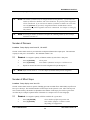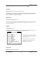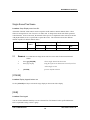
1
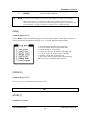
MC 24/48
REFERENCE MANUAL
An Alphabetical Listing of Topics for Quick Answers
REFERENCE MANUAL
NSI CORPORATION
MC 24/48 Version 1.03
2
REFERENCE MANUAL
TABLE OF CONTENTS
-Numbers & Symbols[.] Decimal Point
(1 TO 1)
6
6
6
-A(A/B)
[AND]
[AT]
6
7
7
-B[BLACKOUT]
[BLIND]
7
8
-C(C/D)
[CLEAR]
Channel
(CHANNL)
(CHECK)
[CLEANUP]
(CLEAR)
(COMPRS)
(COPY)
[CUE]
[CUE SHEET]
8
8
9
9
9
9
10
11
11
11
12
-D[DELAY]
(DELETE)
[DEVICE]
[DEVICE]
(DEVICE)
[DIMMER]
Dimmer Protocol
(DISK)
(DISPLAY)
13
13
14
14
14
14
15
16
16
-E[EFFECT]
[ENTER]
16
17
-FFile Name
[FULL]
17
18
-G[GROUP]
18
6
7
8
13
16
17
18
-H-
19
NSI CORPORATION
MC 24/48 Version 1.03
3
REFERENCE MANUAL
19
19
Hand Held Remote
[HELP]
-I-
19
-J-
19
-K-
19
-L(LEVELS)
(LINEAR)
[LINK]
20
20
20
20
-M[M1]-[M8]
(MACRO)
Midi Control
[MINUS]
(MINUTE)
(MORE)
(MP #)
21
21
21
22
22
22
22
-N(NAME)
Network Remote
Number of Channels
Number of Dimmers
Number of Effect Steps
Number of Groups
Number of Macros
Number of Playback Cue Rows
Number of Submaster pages
23
23
23
24
24
25
25
26
26
-OOVERTEMP LED
27
-P[PART]
[PATCH]
[PLAYBACK]
(PORT)
(PORT #)
[PREVIEW]
(PRINT)
Printer type
[PROFILE]
(PROFIL)
27
27
28
28
29
29
29
29
30
31
-Q(Q MODE)
31
21
23
27
27
31
NSI CORPORATION
MC 24/48 Version 1.03
4
REFERENCE MANUAL
32
32
33
33
34
34
34
34
35
-R[RECORD CUE]
[RECORD GROUP]
[RECORD SUB]
Reference by name
(RELALL)
(RENUM)
(RESTOR)
(RT CLK)
-S[S1]-[S8]
Secondary Video
(SELALL)
(SELCUE)
(SELEFF)
(SELGRP)
(SELSUB)
[SETUP]
Show Name
Single Scene/Two Scene
[STAGE]
[SUB]
(SUBP #)
(SYSTEM)
35
35
35
36
36
36
37
37
37
38
38
38
39
39
35
-T[THRU]
[TIME]
[TRACK SHEET]
39
40
40
-U(UNCOMP)
41
-V(VIDEO#)
41
-WWorklight Level
41
39
41
41
41
-X-
42
-Y-
42
-Z-
42
NSI CORPORATION
MC 24/48 Version 1.03
5
REFERENCE MANUAL
-Numbers & Symbols[.] Decimal Point
Location: Data keypad
Use the Decimal Point [.] hard key to insert up to nine additional cues between whole number cues by
assigning them decimal values. You can use decimal values in cue, effect, delay, or follow times. You can
also use the decimal point as a character in a name.
(1 TO 1)
Location: [S6] in PATCH
Use the (1 TO 1) soft key to set a "unity patch" where channel 1 controls dimmer 1, channel 2 controls
dimmer 2. If the number of dimmers is greater than the number of channels, then the channel assignments
will wrap and repeat. For Example, 96 channels and 192 dimmers: Channels 1 through 96 would control
Dimmer 1 through 96 respectively. Dimmer 97 would be assigned to Channel 1 and so forth.
When selected the user will see an Option Menu appear. It will give the options of Cancel. Set ALL 1 to 1
or the ability to set only a specific output port 1 to 1.
-A(A/B)
Location: [S3] in PLAYBACK alternate value (C/D)
The upper portion of the PLACKBACK display shows the most recent list of cues. To the far left appears
a small "A/B", "C/D" or "A/D". This denotes the last executed cue. If you do not see the "A/B" next to a
pressing the (A/B) soft key will scroll the cue display to show what cue is being displays from the A/B
playback fader. If the symbol is "A/D" it mean the SAME cue number was last played on both the A/B and
C/D playback faders. After pressing, the soft key toggles to display (A/B)
NSI CORPORATION
MC 24/48 Version 1.03
6
REFERENCE MANUAL
[AND]
Location: Hard key, Data Key Pad
Use the [AND] hard key to make a channel list, or to make a split time, split delay or split profile. When
the [AND] key is entered as the first keystroke in the Command Line in the Effects display, channels are
added to an existing step.
&
EXAMPLE: To use the [AND] key in the Command Line to address channels and levels:
Channel [1] [AND] [GROUP] [4] [AND] [SUB] [8] [AT] [FL] [ENTER]
@
NOTE: The [AND] key on your console may be labeled "AND" on the key itself. In the Command
Line, this keystroke always appears as "+".
[AT]
Location: Hard key, Data Key Pad
Use the [AT] hard key to assign a channel list to a level, or to make a patching assignment. When the
[AT] key is entered first in the Command Line, the command defaults to all captured channels.
&
EXAMPLE: To assign a level of 80% to channels 25 - 31 in the Stage, Preview, Group,
Submaster and Tracksheet displays:
Channel [25] [THRU] [31] [AT] [80] [ENTER]
-B[BLACKOUT]
Location: Right Console Face, above Grand Master Fader
You can use the Blackout Switch on the console to instantly set channels to zero. When the
[BLACKOUT] Switch is returned to the NORMAL position, the channels return to their previous levels.
The [BLACKOUT] Switch only cuts the output of normal channels; Automated channels with assigned
levels are not affected by the [BLACKOUT] Switch (if you want to set auto-channels to zero, you must
address them directly via keypad or cue).
NSI CORPORATION
MC 24/48 Version 1.03
7
REFERENCE MANUAL
[BLIND]
Location: Right side of console face above Grand Master
The key reserved for future function.
-C(C/D)
Location: [S3] in PLAYBACK alternate value (A/B)
The upper portion of the PLACKBACK display shows the most recent list of cues. To the far left appears
a small "A/B", "C/D" or "A/D". This denotes the last executed cue. If you do not see the "C/D" next to a
cue, pressing the (C/D) soft key will scroll the cue display to show what cue is being displays from the C/D
playback fader. If the symbol is "A/D" it mean the SAME cue number was last played on both the A/B and
C/D playback faders. After pressing, the soft key toggles to display (A/B)
[CLEAR]
Location: Data keypad
Use the [CLEAR] hard key to clear keystrokes entered into the Command Line. The [CLEAR] key also
has the following actions:
q
"Backspace" to erase keystrokes in the Command Line, prior to pressing the [ENTER] key.
q
Release all captured channels from wheel control.
q
Return to previous level of soft keys.
q
Exit dimmer check mode.
q
Dismiss an error message or warning box.
q
Abort actions after receiving a warning message.
RELATED T OPICS:
[ENTER]
NSI CORPORATION
MC 24/48 Version 1.03
8
REFERENCE MANUAL
Channel
Location: n/a
A channel is a control that is assigned a number in the Patch display. In most displays, when a number is
entered first into the Command Line, channels are automatically addressed (there is no Channel key). In
this case, the console inserts the word "Channel" into the Command Line.
You can assign the total number of channels for a particular show in the Setup display. Reducing the
number of channels in the Setup display will not change the patch assignments.
In the Patch display, you can assign dimmers to channels so that one channel may control multiple
dimmers.
(CHANNL)
Location: [S6] in TRACKSHEET
In the TRACKSHEET display, the [S6] soft key, labeled (CHANNL) toggles the Tracksheet display from
the beginning of the stage channel list to the Automated Device list. When pressed, the label of this soft
key changes to display (DEVICE).
(CHECK)
Location: [S5] in PATCH
In the PATCH display, the (CHECK) soft key is used to verify a dimmer by bringing it full on. Once
started the Up and Down Arrow keys will increment the dimmer number allowing for fast verification of
lights and individual dimmers.
&
EXAMPLE: To check dimmers 1, 2 and 3 in the Patch display:
(CHECK) [1] [ENTER]
dimmer 1 on full
[↓]
increment to dimmer 2
[↓]
increment to dimmer 3
[↑]
decrement to dimmer 2
[CLEAR]
to release dimmer
[CLEANUP]
Location: Data keypad
NSI CORPORATION
MC 24/48 Version 1.03
9
REFERENCE MANUAL
Three Tracking modes are available in most displays under the (Q MODE) soft key. Pressing the (Q
MODE) soft key toggles between the three track modes, Tracking, Cue Only, and Cleanup.
You can think of Cleanup mode as "true cue only" mode. This mode displays all non-zero levels as hard
levels, and all zeros, including actual hard zeros, as blank spaces. When you operate in Cleanup mode
exclusively, the concept of tracking levels does not apply. Every cue is recorded as a completely different
set of channels at levels.
When you are working in Tracking or Cue Only Mode, use the CLEANUP mode to assign the Cleanup
attribute to a cue. This prevents any tracking levels from continuing into subsequent cues. In the Cuesheet
and Playback displays, a Cleanup cue is labeled "CLEAN-UP" in the Cleanup column, on the far right side
of the screen (to the right of the Name column).
&
EXAMPLE: To assign a cue the Cleanup attribute in Stage, Patch, Tracksheet and Cuesheet
displays:
[CUE] [#] [CLEANUP] [ENTER]
Cleanup cues have hard levels for all channels including zero levels, thereby preventing any channel levels
tracking into, and beyond the cue. It is possible to restore Tracking from Cleanup. This allows channel
levels to track through at the levels in the previous cue.
&
EXAMPLE: To restore tracking to a channel list in a Cleanup cue from Preview, and
Tracksheet displays:
[# list] [AT] [ENTER]
RELATED T OPICS: (Q MODE)
(CLEAR)
Location: [S2] level II in SETUP
[S7] in PATCH
The (CLEAR) soft key is different from the [CLEAR] hard key.
In the SETUP display, the (CLEAR) bring up to the display
a menu of items for clearing the memory of the console.
These items include Cues, Groups, Submasters, Macros,
Effects or ALL.
NSI CORPORATION
MC 24/48 Version 1.03
10
REFERENCE MANUAL
In the PATCH display, the (CLEAR) soft key brings up to the display a menu of Patch Table items that
may be cleared. The user is allowing to selective "clear" individual patch tables or all patch Tables.
RELATED T OPICS:
(1 TO 1)
in PATCH
(COMPRS)
Location: [S3] in PATCH alternate value (UNCOMP)
The (COMPRS) soft key in the Patch Display is an alternate action key and is used to compress the
display so that un-used dimmers are not shown. Only dimmers assigned to stage channels are visible.
When pressed the value of the soft key will change to display (UNCOMP)
RELATED T OPICS:
(UNCOMP)
[PATCH]
(COPY)
Location: [S4] in PREVIEW, CUESHEET and TRACKSHEET
The (COPY) soft key allows the User to copy the contents of a Cue to another Cue, the contents of a
Submaster to another Submaster or the contents of a Group to another Group.
&
EXAMPLE: To copy a cue to a new cue in PREVIEW
(COPY)
the command line responds
Copy Cue # to Cue
[#]
enter the new number
##
[ENTER]
accept copy with Overwrite warning if new cue existed.
[CUE]
Location: Data keypad
NSI CORPORATION
MC 24/48 Version 1.03
11
REFERENCE MANUAL
You can use the [CUE] hard key to create, select or edit a cue. When you create a new cue, it has a
manual time and no other cue attributes, unless you specify them.
&
EXAMPLE: To select an existing cue or create a new cue (if the cue does not already
exist):
[CUE] [#] [ENTER]
In the example above, this command does not record the current stage levels; it simply creates a new cue as
it would in the Preview display. If you want to record the current stage levels, you must use the [RECORD
CUE] key. When the current track mode is Tracking, the new cue will have soft tracking levels, and will
therefore have the same channel levels as the cue that numerically precedes it. When the current track
mode is Cue Only, the new cue will have hard zeros assigned to any channel that has a level in the
preceding cue. When the current track mode is Cleanup, the new cue will have hard zeros assigned to
every channel in the new cue.
&
EXAMPLE: To create a cue from any display:
[CUE] [#] (enter attributes) [ENTER]
@
NOTE: The contents of the cue are determined by the track mode you are using.
You can also use the [CUE] key to use a cue as a group when setting channel levels. The syntax of the
command is exactly the same as when you use the [GROUP] key.
&
EXAMPLE: To select cue channels at proportional levels:
[CUE] [#] [AT] [#] [ENTER]
RELATED T OPICS:
Cues
(TRACK MODE)
[RECORD CUE]
[CUE SHEET]
Location: Display keypad, bottom row
Use the [CUE SHEET] hard key to show the Cue Sheet Display on the currently selected monitor. The
Cue Sheet display may be used to modify many of the parameters of a recorded cue such as; Time, Delay,
Follow, and Link as well as renumbering, deleting, or naming a cue.
NSI CORPORATION
MC 24/48 Version 1.03
12
REFERENCE MANUAL
-D[DELAY]
You can use the [DELAY] hard key to assign a delay time to a cue, to a split "up" or "down" time, or to a
cue part. The delay indicates the amount of time after pressing the GO button that the fade delays before
starting, after which the fade executes. The Delay column appears in the Cuesheet and Playback displays.
The delay can be split, specifying separate delays for the up time (channels increasing in level) and down
time (channels decreasing in level), including a value of zero.
&
EXAMPLE: To assign a delay in the Stage, Playback, Cuesheet and Preview displays:
[CUE] [#] [DELAY] [#] [ENTER]
&
EXAMPLE: To assign separate delay times to a split time cue:
[CUE] [#] [DELAY] [#] [AND] [#] [ENTER]
&
EXAMPLE: To delete an existing delay:
Select [CUE] [#] [DELAY] [ENTER]
RELATED T OPICS:
[CUE]
[RECORD CUE]
[TIME]
(DELETE)
Location: [S5] in PREVIEW, CUESHEET, and TRACKSHEET
The (DELETE) soft key is used in the PREVIEW, CUESHEET and TRACKSHEET displays to delete a
cue.
&
EXAMPLE: To delete an existing cue:
(DELETE) [#] [ENTER]
(note the system will NOT ask for confirmation)
NSI CORPORATION
MC 24/48 Version 1.03
13
REFERENCE MANUAL
[DEVICE]
Location: Display keypad, bottom row.
Use this button to activate the Device Display. The Device display is arranged to allow the user to see and
adjust the traits of Moving Lights and Automated Lighting Devices.
[DEVICE]
Location: Data key pad, second row.
Use this button to activate the LCD Display to adjust settings for a selected Automated Device.
&
EXAMPLE: To activate LCD display to adjust settings for Device 4:
[DEVICE] [4] [ENTER]
(DEVICE)
Location: [S6] in TRACKSHEET and SETUP
This short-cut soft key simply scrolls the TRACKSHEET display to the right, positioning it at the first
Moving Light or Automated Device. When pressed the value of this key will change to (CHANNL) as its
alternate value.
RELATED T OPICS:
(CHANNL)
[DIMMER]
Location: Data keypad
Use the [DIMMER] hard key for a variety of commands. In the Stage Display, the [DIMMER] key may
be used for Direct Dimmer Control and dimmer check. In the Patch display the [DIMMER] key is used to
patch a dimmer to a channel, or assign dimmer attributes. Note that the same command syntax is used in
both displays, with very different results.
Direct Dimmer Control: In the Stage display, this command bypasses the patch and allows you to
control a dimmer live on stage. It overrides any channel control level, proportional dimmer levels and
NSI CORPORATION
MC 24/48 Version 1.03
14
REFERENCE MANUAL
parked level for the dimmer under direct control. A Direct Dimmer Control window opens in the lower
left corner of the display, showing the dimmer number and its current level. The dimmer level is always
under control of the wheel while the window is open. Any new command dismisses the window and
returns control of the dimmer to the channel that is patched to it.
@
&
NOTE: Direct Dimmer Control overrides any proportional levels or parked dimmer status.
EXAMPLE: To access Direct Dimmer Control in the Stage display:
[DIMMER] [#] [ENTER]
(Use the wheel to set the level.)
- or [DIMMER] [#] [AT] [level] [ENTER]
Patching Commands: In the Patch display, the same syntax assigns a dimmer to a
channel. Since there is no "channel" key, when you enter a number first in the Command Line
without using the [DIMMER] key, it is a channel number by default.
EXAMPLE: To assign dimmer attributes in the Patch display:
[DIMMER] [#] (DIM. LEVEL) [#] [ENTER]
- or [DIMMER] [#] [PROFILE] [#] [ENTER]
etc. ...
Dimmer Protocol
Location: Setup display menu items #13, 14 and 15
The MC 24/48 control console can select between two different dimmer protocols for the output of the
console: DMX512 (the USITT 1990 standard) and CMX (a.k.a. Colortran Multiplex protocol). Most new
system will utilize DMX. If your system is a retrofit to existing Colortran product, you may need CMX.
The console remembers the dimmer protocol setting when you turn the console off, but not when you do a
“hard clear” by holding the [CLEAR] key down while the console boots. Other conditions under which
protocol may need to be reset include; when you update the console to new software or when the RAM
battery is dead
&
EXAMPLE: To assign a protocol for the dimmer output ports:
1.
Press [13] [ENTER]
selects port A menu item
2.
Press [^] or [V]
using the up arrow or down arrow cursor keys select
NSI CORPORATION
MC 24/48 Version 1.03
15
REFERENCE MANUAL
either DMX-512 or CMS
3.
@
[ENTER]
press to confirm selection.
NOTE: If you need to use a dimmer protocol other than DMX512 or CMX, (such as AMX or
analog control) there are a number of commercially available protocol converters.
These can be rented or purchased from theatrical equipment suppliers or from NSI. For
more information, call NSI Corporation Customer Service at (800) 864-2502.
(DISK)
Location: [S4] in SETUP
Use the (DISK) soft key in the SETUP display to activate the Disk sub menu. Shown Below, this menu is
used to read and write information to and from a 3.5", 1.44 Meg, IBM format floppy diskette.
1 = Save currently loaded show to the floppy disk.
2 = Load file already saved on disk into MC 24/48.
3 = Delete existing file saved on disk.
4 = Change the name of a file already on the floppy disk.
5 = Copy an existing file and give copy a new name.
6 = Initialize a floppy disk for first time use.
7 = Re-read the existing operating system from a back-up
diskette or load a new updated system software.
(DISPLAY)
Location: [S3] in SETUP
(This item is reserve for implementation of future feature)
-E[EFFECT]
Location: Data keypad
NSI CORPORATION
MC 24/48 Version 1.03
16
REFERENCE MANUAL
You can use the Effect hard key on the Data Entry Keypad to assign or delete an effect from a cue, load an
effect to a Submaster, or create a channel list from an effect. (The Effect key on the Data Entry keypad is
different from the Select Effect (SELEFF) soft key.)
&
EXAMPLE: To assign an effect to a cue:
[CUE] [#] [EFFECT] [#] [ENTER]
&
EXAMPLE: To remove an effect that is already assigned to a cue:
[CUE] [#] [EFFECT] [ENTER]
&
EXAMPLE: To load an effect to a Submaster in any display:
[RECORD SUB] [#] [EFFECT] [#] [ENTER]
[ENTER]
Location: Data keypad
Use the [ENTER] hard key to execute any command that you have entered into the Command Line.
Pressing [ENTER] may also be a single command to capture all channels above zero, and place them
under wheel control. In the Preview and Tracksheet displays, actual zero levels are captured with the Enter
command because they are "hard" zeros.
When you execute any command in which information is destroyed or replaced, a Warning Message dialog
box requests confirmation before erasing the data, and you must press the [ENTER] key a second time in
order to execute the command.
Most commands require you to press [ENTER] to execute the command, although some commands that
change system settings do not.
RELATED T OPICS:
[CLEAR]
-FFile Name
Location: Setup display menu item #2.
NSI CORPORATION
MC 24/48 Version 1.03
17
REFERENCE MANUAL
Setup menu item 2 provides a way to specify a disk file name for the show in current memory. This name
is different from that of the "Show Name" and must follow MS-Dos naming conventions of a maximum of
11 letters. These will appear as "xxxxxxxx.xxx" if the disk directory were viewed on a PC.
&
EXAMPLE:
To assign a Show Name to a show in the Setup display:
1.
Press [2] on the data keypad.
2.
Using the Submaster bump buttons or an optional ASCI keyboard enter alphanumeric
show name or any number from the channel keypad, press [ENTER].
@
NOTE: The current release of MC 24/48 software does not allow for off-line editing of Show
information.
[FULL]
You can use the [FULL] hard key in the Command Line to bring channel or dimmer levels to 100%.
"AT" is automatically entered into the Command Line when you press [FULL].
&
EXAMPLE: To set a channel level to full:
[#] [FULL] [ENTER]
RELATED T OPICS:
[AT]
-G[GROUP]
Location: Data keypad
You can use the [GROUP] hard key on the Data Entry Keypad to recall a pre-recorded assignment of
channels at levels. You can use the Group key also to create a channel list of specified group channels. A
group may be proportionally controlled by calling for a specific group at a level, in which case all channels
in the group read proportionally. All channels in a group may be controlled by an absolute value by
pressing the [GROUP] key twice before specifying the group number.
&
EXAMPLE: To recall a group at proportional levels in the Stage, Preview, Submaster, Group,
Effect and Tracksheet displays:
NSI CORPORATION
MC 24/48 Version 1.03
18
REFERENCE MANUAL
[GROUP] [#] [AT] [#] [ENTER] (Sets the group channels to their proportional levels,
scaled by the specified level, except in the Effect
display.)
&
EXAMPLE: To select a channel list from a group in absolute, non-proportional, levels in the
Stage, Preview, Submaster, Group, Effect and Tracksheet displays:
[GROUP] [#] [ENTER] [AT] [#] [ENTER]
(Sets all group channels to the specified level)
-HHand Held Remote
Location: n/a
The MC 24/48 control console accepts input from a Hand Held remote. This option, if purchased, allows
most of the console function to be programmed remotely including the recording of Groups, Submasters
and Cues. It also provides the ability to playback cues on the C/D playback faders.
[HELP]
Location: Data keypad
(this key reserved for implementation of future feature)
-I-
-J-
-K-
NSI CORPORATION
MC 24/48 Version 1.03
19
REFERENCE MANUAL
-L(LEVELS)
Location: [S4] in STAGE and PATCH
In the STAGE display, pressing the (LEVELS) soft key will change the display to show the output levels
of the dimmers. In place of the White and Gray channel numbers are RED dimmer numbers and the
current output levels. Additionally, it is possible to address a dimmer or groups of dimmers directly from
this screen.
&
EXAMPLE: To access Direct Dimmer Control in the Stage LEVELS sub display:
[DIMMER] [#] [ENTER]
(Use the wheel to set the level.)
- or [DIMMER] [#] [AT] [level] [ENTER]
RELATED T OPICS:
[DIMMER]
In the PATCH display the (LEVELS) soft key is used to change the PATCH display from the proportional
patch to the profile display. When pressed the value of this key changes to (PROFIL)
RELATED T OPICS:
(PROFIL)
(LINEAR)
Location: [S2] in PATCH alternate value (PORT)
The Patch display of the MC 24/48 may be viewed with the dimmers numbers in a linear fashion
(consecutive 1 through.. ##) or they may be viewed by dimmer port. When the (LINEAR) soft key is
pressed, the dimmer numbers are arranged consecutively and the value of the soft key changes to (PORT).
RELATED T OPICS:
(PORT)
[LINK]
NSI CORPORATION
MC 24/48 Version 1.03
20
REFERENCE MANUAL
Location: Data keypad
You can use the [LINK] hard key to assign links to cues. Links allow cues to execute out of numeric
sequence. The link cue attribute is available in the Stage, Preview, and Cuesheet displays.
&
EXAMPLE: To make cue 200 execute after cue 17:
[CUE] [17] [LINK] [200] [ENTER]
&
(Cues 18 and up do not execute.)
EXAMPLE: To assign a link to a cue in the Stage, Preview and Cuesheet displays:
[CUE] [#] [LINK] [#] [ENTER]
-M[M1]-[M8]
Location: Display keypad, middle row.
Used to playback a recorded macro. Refer to MACROS for further description.
RELATED T OPICS:
(MACRO) Soft key in Set-Up Display
(MACRO)
Location: [S3] in PREVIEW and CUESHEET level II
[S5] in SETUP
In the PREVIEW and CUESHEET displays the (MACRO) soft key is used to assign a Macro to a cue.
Midi Control
Location: Setup display menu item #17
(this item reserves for future feature implementation)!
NSI CORPORATION
MC 24/48 Version 1.03
21
REFERENCE MANUAL
[MINUS]
Location: Data keypad
Use the [MINUS] hard key to subtract channels from within a list of channels, or to subtract channels from
an existing effect step. You can use the [MINUS] key in the Command Line to subtract items from the
command. You can also use the [MINUS] key at the beginning of a record command to prevent recording
specified channels.
&
EXAMPLE: To use the [MINUS] key in the Command Line to address channels and levels:
[GROUP] [1] [MINUS] [CHANNEL] [3] [AT] [FL] [ENTER]
- or [1] [THRU] [100] [MINUS] [GROUP] [1] [AT] [FL] [ENTER]
RELATED T OPICS:
Channel Lists
(MINUTE)
Location: [S3] when any time key is pressed [TIME], [DELAY] and [FOLLOW] in CUESHEET,
TRACKSHEET and PLAYBACK or EFFECT
When entering a time value for fades or effect steps, the MC 24/48 will allow up to 99.9 seconds to be
entered. However since the MC 24/48 will also allow fades up to 99 minutes this soft key is used to
identify when inputting minutes or seconds.
(MORE)
Location: [S8] in PREVIEW, DEVICE, CUESHEET, TRACKSHEET, and SETUP
Anytime the [S8] key displays a value of (MORE), this means there are additional soft key function
accessible. Pressing the (MORE) key will change the soft key assignments to the next level.
(MP #)
Location: [S2] in STAGE, PREVIEW, CUESHEET, and PLAYBACK
NSI CORPORATION
MC 24/48 Version 1.03
22
REFERENCE MANUAL
The (MP #) soft keys is used to select which page of Macros are active on the [M1] - [M8] Macro keys.
Each page of macros contains 8 recordable macros.
&
EXAMPLE: To change the from macro page 1 to macro page 2:
1.
(MP 1)
command line responds "Macro Page"
2.
[#] [ENTER]
enter number of new macro page, 2 in this case
-N(NAME)
Location: [S6] in PREVIEW, CUESHEET
The (NAME) soft key activates the alphanumeric mode of the MC 24/48 allowing the user to enter, Cue,
Group or Submaster Names.
Network Remote
Location: Set-up display, menu item #20
(this item reserved for future feature implementation)
Number of Channels
Location: Set-up display, menu item #7
The maximum number of control channels on the MC 24/48 control console is 384. This number should
not be confused with the number of manual channel faders. The valid number range for this menu item is
48 to 384 depending on the requirement of your show.
&
&
EXAMPLE: To assign the quantity of channels available for a given show:
1.
[7] [ENTER]
selects Number of Channels menu item
2.
[#] [ENTER]
enter number of channels. Valid 48 to 384
EXAMPLE: To set up a show with 200 channels:
1.
[7] [ENTER]
NSI CORPORATION
MC 24/48 Version 1.03
23
REFERENCE MANUAL
2.
@
[200] [ENTER]
NOTE: The number of channels may be changed without clearing memory. If you reduce the
number of channels or dimmers, and restore them later, the previous patch assignments
will be remembered. If you increase the number of channels or dimmers in a show that
was read from disk, any previously assigned Non-Dim or Parked dimmers will be
remembered, but patch assignments will not be remembered. See Chapter 5, Setting Up
The ft Patch.
@
NOTE: Increasing the number of channels will affect the remaining number of Cues, Groups,
Submasters and macros.
Number of Dimmers
Location: Setup display menu items #3, #4 and #5.
The MC 24/48 control console is provided with 3 multiplexed dimmer data output ports. The maximum
capacity of each port is 512 dimmers. The minimum number is 48.
&
@
EXAMPLE: To assign the quantity of dimmers address by each of the 3 data ports:
1.
Press [3] [ENTER]
selects port A
2.
Press [#] [ENTER]
enter number of dimmers on this port. Valid 48 to 512
3.
Repeat for menu items 4 and 5 to make assignment for port B and port C
NOTE: Refer to menu items 13 - 15 in this chapter for dimmer data protocol assignment.
Number of Effect Steps
Location: Setup display menu item #10.
The MC 24/48 control console is capable of holding up to 600 recorded effects. Individually any effect can
have up to 100 steps. The maximum number of effect steps for the system is 9,999. Since each step uses
some console memory, this number is adjustable to the number of total steps you need for a given show.
An effect may be a simple sequential chase of channels or a complex series of Cues and groups.
&
EXAMPLE: To assign the quantity of Effects available for a given show:
1.
Press [10] [ENTER]
selects Number of Effect Steps menu item
2.
Press [#] [ENTER]
enter number of Effects. Valid 0 to 9,999*
*depending on configuration
NSI CORPORATION
MC 24/48 Version 1.03
24
REFERENCE MANUAL
@
NOTE: Increasing the number of Effect Steps will affect the remaining number of Cues, Groups
and Submaster pages.
F
ADVANCED T OPICS: Refer to Chapter 15 Effects for addition information on the operation of
and programming of Effects.
Number of Groups
Location: Setup display, menu item #11.
The MC 24/48 control console is capable of holding up to 500 Groups. A Group is a recorded sequence of
channels and levels, similar to a cue but without timing information. The primary purpose for a group is
fast recall of a series of related channels and their proportionate levels for easy setting of levels in the
creation of cues.
&
@
EXAMPLE: To assign the quantity of groups available for a given show:
1.
Press [11] [ENTER]
selects Number of Groups menu item
2.
Press [#] [ENTER]
enter number of Groups. Valid 0 to 500*
*depending on configuration
NOTE: Increasing the number of Groups will affect the remaining number of Cues, Macros,
Effects and Submaster pages.
F
ADVANCED T OPICS: Refer to Chapter 14 Groups for addition information on the operation
of and programming of groups.
Number of Macros
Location: Setup display menu item #9.
The MC 24/48 control console is capable of holding up to 500 macros. A Macro is a recorded sequence of
commands that may be played back with the touch of one of the 8 macro keys in the Display keypad.
&
EXAMPLE: To assign the quantity of macros available for a given show:
NSI CORPORATION
MC 24/48 Version 1.03
25
@
1.
Press [9] [ENTER]
2.
Press [#] [ENTER]
REFERENCE MANUAL
selects Number of Macros menu item
enter number of Macros. Valid 0 to 500*
*depending on configuration
NOTE: Increasing the number of macros will affect the remaining number of Cues, Groups and
Submaster pages.
F
ADVANCED T OPICS: Refer to Chapter 21 Macros for addition information on the operation
of and programming of Macros.
Number of Playback Cue Rows
Location: Setup display menu item #6.
(this item reserved for future feature implementation)
Number of Submaster pages
Location: Setup display menu item #8.
The MC 24/48 control console is capable of holding up to 8 pages of Submaster assignments depending on
the specific setting selected by the user. Each "page" can contain up to 24 Submaster assignments
corresponding to the 24 Submasters and their associated bump buttons. In the maximum configuration this
would allow a total of 192 assignments.
&
@
EXAMPLE: To assign the quantity of Submaster pages for a given show:
1.
Press [8] [ENTER]
selects Number of Submaster Pages menu item
2.
Press [#] [ENTER]
enter number of pages. Valid 1 to 8
NOTE: Increasing the number of Submaster pages will affect the remaining number of Cues,
Groups and macros.
F
ADVANCED T OPICS: Refer to Chapter 7 Basic Submaster Operation and Chapter 14
Advanced Submaster Operation for addition information on the
operation of Submasters and Submaster pages.
NSI CORPORATION
MC 24/48 Version 1.03
26
REFERENCE MANUAL
-OOVERTEMP LED
Location: Indicator, Right Console Face, above [BLACKOUT] Hard key
The red OVERTEMP LED illuminates when a dimmer rack is close to automatically turning itself off due
to an obstructed air flow. This feature only works when the console is connected to a Colortran Dimmer
Rack.
-P[PART]
Location: Data keypad
(this key reserved for implementation of future features)
[PATCH]
Location: Display keypad, bottom row
Use the [PATCH] display hard key to change the screen to the Patch display. The Patch display is a used
to assign control channels to dimmers. The Profile, Non-Dim Dimmers, and Parked Dimmers displays are
also available in the Patch display, under their respective soft keys.
A channel may control multiple dimmers. Any dimmer may be given a proportional level. If a dimmer has
previously been assigned to a channel, and it is subsequently patched to another channel, it is robbed from
the previous patch location. To subtract a single dimmer assignment and retain the other assignments for
the currently selected channel, use the [MINUS] key.
In the Patch: By Channel and Patch: By Dimmer formats, the first column lists each dimmer or channel in
numeric order. The second column lists the patch assignment, in numeric order. The third column, Level
%, lists the dimmer level, which is the proportional level for that dimmer. The fourth column, Profile, lists
the profile assigned to the dimmer.
A dimmer may be parked, assigned a custom profile or assigned virtual non-dim status. You can also
select the Profile Editor display from the Patch display.
NSI CORPORATION
MC 24/48 Version 1.03
27
REFERENCE MANUAL
EXAMPLE: To patch a channel to a dimmer in the Patch display:
[#] [AT] [# list] [ENTER]
EXAMPLE: To patch by dimmer in the Patch display:
[DIMMER] [# list] [AT] [#] [ENTER]
EXAMPLE: To remove a single dimmer from the currently selected channel:
[MINUS] [DIMMER] [#] [ENTER]
EXAMPLE: To assign a proportional level to a dimmer when patching:
[#] [AT] [#] (DIM LEVEL) [#] [ENTER]
RELATED T OPICS:
[DIMMER]
(LEVEL)
[PROFILE]
(PROFIL)
[PLAYBACK]
Location: Display keypad, bottom row.
You can use the [PLAYBACK] Display hard key to change the screen to the Playback display. The cues
are displays in gray with the current cue in White. The Playback display updates the Submaster level and
sub type, and the current status of the cues running on playback faders. The Playback display Status bar
shows the Stage Cue and the Next Cue.
RELATED T OPICS:
(A/B)
(SubP #)
(C/D)
(Q Mode)
(PORT)
Location: [S2] in PATCH alternate value (LINEAR)
The Patch display of the MC 24/48 may be viewed with the dimmers numbers in a linear fashion
(consecutive 1 through.. ##) or they may be viewed by dimmer port. When the (PORT) soft key is pressed,
the dimmer number change and each data out put is numbered 1a, 2a ... 1b, 2b... 1c, 2c.. etc. This is
NSI CORPORATION
MC 24/48 Version 1.03
28
REFERENCE MANUAL
especially useful with automated devices and when using a number or portable dimmer packs where
starting addresses are important. The value of this soft key changes to (LINEAR).
(PORT #)
Location: [S1] in PATCH values Port A, Port B or Port C
The (PORT #) soft key is designed to move the Patch Display to the first dimmer from the selected Port.
Whether using the "Port" or "Linear" numbering, the key will shift the display. When pressed the value
changes from (PORT A) to (PORT B) to (PORT C).
[PREVIEW]
Location: Display keypad, bottom row.
Used to activate the Preview Display. When first pressed, display shows the contents of the last previewed
item. To select a different item to preview, use the soft keys in that display to select preview of a Cue,
Group, Effect or Submaster.
(PRINT)
Location: [S2] in SETUP
The (PRINT) soft key in the SETUP display is used to activate the print sub menu (Shown Below). From
this menu a number of items can be printed out to hard copy for future reference.
The user may enter any or all digits from [1]
through [9] to select the printing of individual
elements of show data.
Pressing [0] will select to print everything.
After making desired selection(s) press the
[ENTER] key to begin printing.
Printer type
Location: Setup display menu item #16.
NSI CORPORATION
MC 24/48 Version 1.03
29
REFERENCE MANUAL
The MC 24/48 control console is capable of sending information to one of two types of printers. This
feature will allow users to print show information to hard copy. The two printer types are HP Laser Jet and
Epson LX series. Consult your printer manual for compatibility requirements.
&
EXAMPLE: To define the printer output:
1.
Press [16] [ENTER]
selects Printer type menu item
2.
Press [á] or [â]
using the up arrow or down arrow cursor keys select
either HP LaserJet or Epson LX series
3.
@
Press [ENTER]
to confirm selection.
NOTE: Refer to Chapter 12 Utilities, Warnings, Printing, and Default Settings for additional
information on printing.
[PROFILE]
Location: Data keypad
You can use the [PROFILE] hard key to assign a profile to a cue or dimmer. The output fade curve may
be customized to your specifications. Every fade point of the fade curve may be specified.
A profile may be assigned to any cue or dimmer. A profile is assigned to a dimmer in the Patch display.
&
EXAMPLE: To assign a profile to a cue in the Stage, Playback, Preview, Cuesheet or Tracksheet
displays:
[CUE] [#] [PROFILE] [#] [ENTER]
(Assigns profile to indicated cue.)
- or [PROFILE] [#] [ENTER]
(Assigns profile to current preview cue.)
- or [PROFILE] [#] [AND] [#] [ENTER]
(Assigns separate profiles to the "up" and
"down" time of a split cue.)
&
EXAMPLE: To assign a profile to a dimmer in the Patch display:
[DIMMER] [# list] [PROFILE] [#] [ENTER] (Assigns profile to indicated dimmers.)
- or -
NSI CORPORATION
MC 24/48 Version 1.03
30
REFERENCE MANUAL
(Assigns profile to current dimmer.)
[PROFILE] [#] [ENTER]
&
EXAMPLE: To delete a profile assignment in the Stage, Preview, Cuesheet or Tracksheet
displays, do not specify a profile number:
[CUE] [#] [PROFILE] [ENTER]
&
EXAMPLE: To delete a profile assignment in the Patch display, do not specify a profile number:
[DIMMER] [# list] [PROFILE] [ENTER]
RELATED T OPICS:
[CUE]
[DIMMER]
[PATCH]
(PROFIL)
(PROFIL)
Location: [S4] in PATCH alternate value (LEVELS)
[S7] in SETUP
In the PATCH display the (PROFIL) soft key toggles the display from showing patch assignments with
proportional levels to showing the dimmer fade profile number associated with that patch assignment.
Profile "00" is the default profile. The user may program profiles #1 through #15 to create fade profiles for
Non-dims and other lighting sources.
-Q(Q MODE)
Location: [S1] in STAGE, PREVIEW, DEVICE, CUESHEET, TRACKSHEET and PLAYBACK
Use the (Q MODE) soft key in most displays to select one of the three Q Modes in which to operate the
console. Every time you press the (Q MODE) soft key it changes the current Q Mode between Tracking,
Cue Only, and Cleanup modes.
The active Q Mode determines how cue recording and edit commands affect cues. You can change the
current Q Mode anytime prior to executing a command with the [ENTER] key. The current Q Mode is
shown immediately to the left of the Command Line.
Tracking Q Mode: In Tracking Q Mode, cues are recorded so that levels that change from the
previous cue are assigned "hard" (non-tracking) values, while levels that do not change are assigned "soft"
(tracking) values. When you edit a level in the previous cue in Tracking mode, the change will "track
NSI CORPORATION
MC 24/48 Version 1.03
31
REFERENCE MANUAL
through" into the following cues. If you want to stop the change from tracking through beyond a certain
cue, assign that cue the Cleanup attribute. If you create a cue blind in the Preview, Cuesheet, Playback, or
Tracksheet displays while in Tracking mode, the cue will have the same levels as the preceding cue.
Cue Only mode: In Cue Only mode, cues are recorded live exactly as they are in Tracking mode. If
you create a cue "blind" in the Preview, Cuesheet, Playback, or Tracksheet displays while in Cue Only
mode, the cue will have hard zeros assigned to it in channels that had non-zero levels in the previous cue
(i.e., it will be a blank cue with no active levels). When you make edits to a cue in Cue Only mode, the
level will change in that cue only, and the change will not track through into the following cues.
Cleanup mode: In Cleanup mode, you may treat the console as if tracking (soft) levels do not exist.
Every level is hard and zeros are not shown in any display. When you record a cue in Cleanup mode,
every channel has its value recorded completely independent of the channels value in the previous cue.
When you edit a cue in Cleanup mode, the result is the same as editing in Cue Only; no changes track
through to following cues. If you create a cue blind in the Preview, Cuesheet, Playback or Tracksheet
displays while in Cleanup mode, the cue will have no levels (all hard zeros) assigned to it.
@
NOTE: If you record or create a cue blind while in Cleanup mode, and then switch to another Q
Mode, that cue will contain all hard levels, including hard zeros. The cue will also have
the Cleanup attribute assigned to it. If you switch to Cleanup mode after you have
recorded cues in the other modes, those cues will not appear to have any tracking (soft)
levels. However, they actually retain their tracking status, as you can see if you later
return to the other Q Modes. If you never use tracking, it is advisable to work in
Cleanup mode exclusively, rather than changing between it and other modes.
The easiest way to demonstrate and learn the way that the three Q Modes work is to try the same
commands in different Q Modes, while working in the Tracksheet display.
RELATED T OPICS:
[CLEANUP]
[TRACKSHEET]
[RECORD CUE]
[CUE]
-R[RECORD CUE]
Location: Data keypad
NSI CORPORATION
MC 24/48 Version 1.03
32
REFERENCE MANUAL
Use the [RECORD CUE] hard key to record the current "look" on stage as a cue. If the indicated cue
already exists, an Overwrite Warning message appears and requests confirmation before overwriting the
previously recorded cue. You must press the [ENTER] key a second time to confirm, or press the
[CLEAR] key to cancel the command. The Track mode may be selected any time before the [ENTER]
key is selected. In the Stage display, any edits to a live cue are not recorded unless the Record Cue function
is executed.
&
EXAMPLE: The following example shows all different combinations of cue attributes available
in a Record Cue command. The order of attributes is not important, and the
commas are shown here only for clarity:
[RECORD CUE] [#], [PART] [#], [TIME] [#] [AND] [#], [DELAY] [#] [AND] [#],
[FOLLOW] [#], [PROFILE] [#] [AND] [#], [LINK] [#], [EFFECT] [#], [ENTER]
RELATED T OPICS:
[CUE]
[PREVIEW]
[STAGE]
(TRACK MODE)
[RECORD GROUP]
Location: Data keypad
You can use the [RECORD GROUP] hard key to record the current stage "look" to a specified group
number. If the indicated group already exists, an Overwrite Warning message appears and requests
confirmation before overwriting the previously recorded group. You must press the [ENTER] key a
second time to confirm, or press the [CLEAR] key to cancel the command.
&
EXAMPLE: To record a group live from any display:
[RECORD GROUP] [#] [ENTER]
[RECORD SUB]
Location: Data keypad
Use the [RECORD SUB] hard key to record the current stage "look" to a specified Submaster. The
Record Submaster command takes a picture of the stage display levels and records the Submaster,
replacing the levels (if any) previously assigned to the Normal Submaster. This command changes the
mode of the indicated Submaster to Normal mode.
&
EXAMPLE: To record a Submaster "live" from any display:
[RECORD SUB] [#] [ENTER]
NSI CORPORATION
MC 24/48 Version 1.03
33
REFERENCE MANUAL
Reference by name
Location: Setup display, menu item #18.
(This item is reserve for implementation of future feature)
(RELALL)
Location: [S3] in DEVICE
Use the (RELALL) soft key to release all Device Traits. When traits are released they do not record into
Cues, Groups or Submasters.
(RENUM)
Location: [S3] in PREVIEW, CUESHEET and TRACKSHEET
Use the (RENUM) soft key to renumber an existing cue with a new number. Valid Cue numbers are .1 to
999.9
(RESTOR)
Location: [S7] in STAGE, PREVIEW and TRACKSHEET
The (RESTOR) soft key is use to restore channel level to a previous state.
&
EXAMPLE: To restore channel levels from the Stage, Preview, Group, Submaster and
Tracksheet displays:
(RESTOR) [ENTER]
(Restores all channels.)
- or (RESTOR) [# list] [ENTER]
(Restores only the channels in list.)
Using the (RESTOR) soft key repeatedly toggles between the last two consecutive levels that a channel has
been assigned.
NSI CORPORATION
MC 24/48 Version 1.03
34
REFERENCE MANUAL
&
EXAMPLE: To toggle a channel's last two assigned levels in the Stage, Preview, or Tracksheet
displays:
1.
[# list] [AT] [#] [ENTER]
2.
(RESTOR) [ENTER]
(Displays channel levels set before last level setting
command.)
3.
(RESTOR) [ENTER]
(Toggles back to the new levels set by the last
command.)
(RT CLK)
Location: [S3] in level II of SETUP
(This item is reserve for implementation of future feature)
-S[S1]-[S8]
Location: Display keypad, top row.
Use to select a soft key function for a current display mode. Refer to SOFTKEYS for a list of functions or
to the specific function name for a description of that function. Note: Soft keys are listed in parenthesis.
Secondary Video
Location: Setup display, menu item 22
(This item is reserve for implementation of future feature)
(SELALL)
Location: [S2] in DEVICE
NSI CORPORATION
MC 24/48 Version 1.03
35
REFERENCE MANUAL
Use the (SELALL) soft key in the DEVICE display to select ALL traits of ALL devices for recording.
(SELCUE)
Location: [S2] in PREVIEW, CUESHEET, and TRACKSHEET
When in the PREVIEW, CUESHEET or TRACKSHEET displays the (SELCUE) soft key allows the user
to change which cue is active for editing.
(SELEFF)
Location: [S5] in STAGE, PREVIEW
When entering the PREVIEW display, or when changing modes in the PREVIEW display, use the
(SELEFF) soft key to select an Effect to preview.
&
EXAMPLE: To select an Effect to edit in PREVIEW display:
(SELSUB) [#] [ENTER]
When in the STAGE display, use the (SELEFF) soft key to select an Effect to program.
&
EXAMPLE: To select an Effect to edit in STAGE display:
(SELSUB) [#] [ENTER]
(SELGRP)
Location: [S3] in PREVIEW
When entering the PREVIEW display, or when changing modes in the PREVIEW display, use the
(SELGRP) soft key to select a Group to preview.
&
EXAMPLE: To select a Group to edit in PREVIEW display:
(SELGRP) [#] [ENTER]
NSI CORPORATION
MC 24/48 Version 1.03
36
REFERENCE MANUAL
(SELSUB)
Location: [S4] in PREVIEW
When entering the PREVIEW display, or when changing modes in the PREVIEW display, use the
(SELSUB) soft key to select a Submaster to preview.
&
EXAMPLE: To select a Submaster to edit in PREVIEW display:
(SELSUB) [#] [ENTER]
[SETUP]
Location: Display keypad, bottom row.
Use the [SETUP] hard key to change the current video monitor to the Setup display. The Setup display
shows all information concerning the configuration of the system for a show, and allows you to view and
edit the information. All operating parameters are displayed along with their current status. You can set
each parameter using its corresponding menu item or soft key. The top of the display shows the console
model and the software version currently installed. The Setup display indicates the number of cues and
groups available to record in the show, along with the file name and show name of the current show.
Show Name
Location: Setup display menu item #1.
Setup menu item 1 provides a way to add an alphanumeric label to a show file. The Show Name is
different than the show File Name. The Show Name only appears in the Setup display, and can only be
viewed when the show is in active memory.
&
EXAMPLE: To assign a Show Name to a show in the Setup display:
1.
Press [1] on the data keypad.
2.
Using the Submaster bump buttons or an optional ASCI keyboard enter alphanumeric
show name or any number form the channel keypad, press [ENTER].
NSI CORPORATION
MC 24/48 Version 1.03
37
REFERENCE MANUAL
Single Scene/Two Scene
Location: Setup Display menu item #21.
All models of the MC 24/48 control console except the model 600 have manual channel sliders. These
sliders are arranged in two row of 24, 48 or 72 slider each. In Single Scene mode each slider represent a
control channel. In two scene mode, the channels of the top row are duplicated on the second row and the
A/B playback fader serves as a split-fader to operate the scenes. The chart below shows the different
channel capacities of manual channel sliders.
MODEL
MC 24/48
&
Total
Faders
Single Scene
Top Row
Second Row
Two Scene
Top Row
48
1 - 24
25 - 48
1 - 24
Second
Row
1 - 24
EXAMPLE: To switch between Single Scene and Two-Scene mode for the manual channel
sliders:
1.
Press [21] [ENTER]
selects single Scene/Two Scene item
2.
Press [á] or [â]
using the up arrow or down arrow cursor keys select
either Single or Two
3.
[ENTER]
press to confirm selection.
[STAGE]
Location: Display keypad, bottom row.
Use the [STAGE] hard key to activate the stage display on the currant video display.
[SUB]
Location: Data keypad
You can use the Submaster hard key to create a channel list of all channels in the specified Submaster.
This is equivalent to using a sub as a group.
NSI CORPORATION
MC 24/48 Version 1.03
38
REFERENCE MANUAL
&
EXAMPLE: To create a channel list of proportional levels of a Submaster in the Stage, Preview
and Tracksheet displays:
[SUB] [#] [AT] [#] [ENTER]
&
EXAMPLE: To create a channel list from a Submaster at the absolute (non-proportional) levels
in the Stage, Preview, Submaster, Group and Tracksheet displays:
[SUB] [#] [ENTER] [AT] [#] [ENTER]
(SUBP #)
Location: [S6] in STAGE, PREVIEW and PLAYBACK
Use the (SUBP #) soft key to change the currently assigned Submaster page. The number following the
word "page" indicates the current page. The assignments change only for Submasters that are set to a level
of zero. If the console has been set to have 3 Submaster pages, repeated pressing of this key will change it
from (SubP 1) to (SubP 2) to (SubP 3).
RELATED T OPICS:
Number of Submaster Pages
(SYSTEM)
Location: [S1] in SETUP
In the SETUP display, there are a number of sub displays and menus. Pressing the (SYSTEM) soft key
will always return the user to the main SETUP Display.
-T[THRU]
Location: Data keypad
Use the [THRU] hard key to sequence between selected items in the Command Line. Items may be
sequenced in either direction.
&
EXAMPLE: To use the [THRU] key in the Command Line to list channels and levels:
NSI CORPORATION
MC 24/48 Version 1.03
39
REFERENCE MANUAL
[#] [THRU] [#] [AT] [ENTER]
[TIME]
Location: Data keypad
Use the [TIME] hard key in the Stage, Preview, Cue Sheet, Tracksheet displays to create or edit the time
fade parameters of a recorded cue.
[TRACK SHEET]
Location: Display keypad, bottom row.
Use the [TRACK SHEET] hard key to show the Track Sheet display on the currently selected monitor.
The purpose of the Tracksheet display is to allow the channel levels of a number of cues or cue parts to be
compared, created and edited. The contents of cues may be edited from this display in "blind" mode only,
and may be viewed when the cue is re-executed. Changes to cues are permanent as they are made. The
soft keys available in the Tracksheet display are:
q
(Q MODE)
(Selects Track mode: Tracking, Cue Only, or Cleanup.)
q
(SELCUE)
(Selects a specific cue.)
q
(RENUM)
(Renumbers a cue.)
q
(COPY)
(Copies a cue.)
q
(DELETE)
(Deletes a specified cue.)
q
(NAME)
(Use to assign an Alpha name to a cue.)
q
(Video2)
(Activate the 2nd Video Display)
The display shows 24 channels horizontally across the display. You can use the Right and Left Arrow
keys to view additional channels. Cues are listed vertically, use the Up and Down Arrow keys to view
additional cues.
RELATED T OPICS:
(COPY)
(NAME)
(RENUM)
(VIDEO2)
(DELETE)
(Q MODE)
(SELCUE)
NSI CORPORATION
MC 24/48 Version 1.03
40
REFERENCE MANUAL
-U(UNCOMP)
Location: [S3] in PATCH alternate value (COMPRS)
The (UNCOMP) soft key in the Patch Display is an alternate action key and is used to uncompress the
display so that all dimmers are shown. When pressed the value of the soft key will change to display
(COMPRS)
RELATED T OPICS:
(COMPRS)
[PATCH]
-V(VIDEO#)
Location: [S8] in STAGE, DEVICE, CUESHEET, PLAYBACK and PATCH
[S1] in level II of SETUP
(This item is reserve for implementation of future feature)
-WWorklight Level
The MC 24/48 control console, depending on model, has two or three connectors on the back
panel for the optional gooseneck worklights. If this option was purchased, the number set here is
the output level.
&
EXAMPLE: To assign an intensity level for the console worklights:
NSI CORPORATION
MC 24/48 Version 1.03
41
1.
Press [12] [ENTER]
REFERENCE MANUAL
selects Worklight Level menu item
2.
Press [#] [ENTER]
enter the desire level. Valid 0 to 100
-X-
-Y-
-Z-
NSI CORPORATION
MC 24/48 Version 1.03
42