1
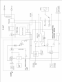
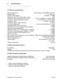
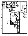
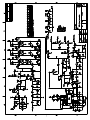
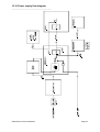
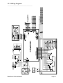
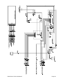
FM30 FM EXCITER/TRANSMITTER & Transposer Installation, Operator and Service Manual Eddystone Broadcast Limited, Broadcast House, Lauriston Park, Pitchill, Evesham. WR11 8SN Telephone (+44) 1386 871650 Fax (+44) 1386 871987 Email [email protected] www.eddystone-broadcast.com CONTENTS 1 2 3 4 5 6 7 8 9 10 11 Introduction Safety, Electrical hazard Safety, Toxic hazard Unpacking Controls and Connectors Installation Block diagram Specifications Contacting Eddystone Broadcast Limited Technical Section Contents Declaration of conformity No part of this manual may be reproduced or transmitted in any form or by any means, electronic or mechanical, including photocopying, recording or information storage and retrieval systems, for any purpose other than the purchaser's personal use, without the express written permission of Eddystone Broadcast Ltd. Information in this document is subject to change without notice and does not represent a commitment on the part of Eddystone Broadcast Ltd. Eddystone Broadcast Ltd shall not be liable for any direct, indirect, consequential or incidental damages as a result of the use or misuse of this equipment, handbook or any related materials. FM30 Series Technical Manual Page 2 1 Introduction )))))))))))))))))))))))))))))))))) The FM30 is a top specification broadcast FM exciter that is also ideally suited as a low power stand alone transmitter. Featuring wideband design techniques, frequency adjustment is easily achieved by internally set direct reading dial switches - no further tuning is required. Both the international 87.5-108MHz and Japanese 76-90MHz frequency bands are catered for. The FM30 uses the renowned sbs ultra linear modulator to give superb sound reproduction with freedom from overshoots and artifacts. It will operate into any load without damage thanks to its VSWR cut back circuit that protects the power amplifier stage from adverse operating conditions. The FM30 front panel metering shows forward and reflected power together with internal voltages and the modulation level. Additionally a monitor point for RF output is provided. Quick-view status monitoring using dual colour LEDs indicate that PLL lock, forward power and reflected power are within a preset tolerance when green. The rear panel includes a remote control/monitoring socket that allows carrier muting and status signalling to an external system. Very conservatively rated components and a switch mode DC-DC converter are used to ensure extremely high reliability and to give good efficiency. The FM30 is in service with broadcasters worldwide and has been giving many years of trouble-free service. The FM30 is available with an unbalanced multiplex/composite input (FM30), mono balanced with limiter (FM30/M) and balanced stereo with built in stereo limiter/encoder (FM30/S). The FM30/RBRX includes a high quality single channel receiver module based on the sbs RX400. The FM30/RBRX is a fully self contained transposer, ideal for relay stations. A digital input version (AES/EBU) with stereo encoder is also available. Additionally the FM30 is available with an input mixer for mixing balanced/unbalanced multiplex/composite with three SCA and a balanced mono input with 0, 50 and 75uS pre-emphasis. All versions of the FM30, apart from the multiplex/composite input type have a switchable multiplex/composite loop for the addition of RDS or any other SCA system. The FM30 can be used with the sbs ACU3, ACU4 or E2075 changeover unit where a fully backed up (redundant) system is required. FM30 Series Technical Manual Page 3 2 Safety, Electrical hazard )))))))))))))))))))))))))))))))))) Important Notice This unit contains high voltages which could be fatal. YOU MUST ALWAYS ISOLATE THE UNIT FROM THE MAINS SUPPLY BY COMPLETELY DISCONNECTING IT BEFORE ATTEMPTING TO OPEN THE CASE. THIS EQUIPMENT MUST BE EARTHED. Do not expose this equipment to rain or any other source of water. In common with all mains operated equipment, only suitably trained competent personnel should attempt to adjust, modify or repair this equipment or operate it with the cover removed. In case of any query please contact your local agent or sbs. Any unauthorised adjustment, modification or repair of this equipment may invalidate any warranty and/or safety approvals that apply. Please read all of this manual and familiarise yourself with the controls before attempting to use this equipment. To ensure safety, it is the responsibility of the user to install and operate this equipment in a manner that is within the manufacturers specifications. FM30 Series Technical Manual Page 4 3 Safety, Toxic hazard )))))))))))))))))))))))))))))))))) This equipment includes devices which contain Beryllium Oxide which is a highly toxic substance. Inhalation or ingestion of even tiny particles could be injurious to health or even FATAL! Extreme care must be exercised when replacing and discarding components which may contain Beryllium Oxide. If any such device is physically damaged you should seek expert advice, e.g. by contacting the device's manufacturers. All such devices must be disposed of in accordance with local regulations. In the UK your local council will have a toxic waste disposal department who will be able to advise you. Elsewhere you should contact the responsible authorities. NEVER DISPOSE OF A DEVICE CONTAINING BERYLLIUM OXIDE WITH GENERAL WASTE. FM30 Series Technical Manual Page 5 4 Unpacking )))))))))))))))))))))))))))))))))) This package should contain:1x 1x 1x FM30 Series broadcast exciter/transmitter IEC Power lead FM30 series manual If any items are missing or damaged please inform your supplier immediately. Initial Checks Ensure that the FM30 has been set to the correct power/line voltage for your country. FM30 Series Technical Manual Page 6 5 Controls and Connectors )))))))))))))))))))))))))))))))))) Front Panel: PLL LOCK Modulator functioning correctly (when green). P.FWD Green when the RF output level is above a predetermined level (see installation section). P.REF Green while the reflected RF power is below a predetermined level (see installation section). Red when the VSWR cut-back system is operating. LIMIT Shows green when internal limiter option is limiting audio input level. SIGNAL (FM30/RBRX) Green while a signal is received. Red when signal is absent or below the preset mute level. O/P Monitor Monitor of RF output (approx. -40dBc). This point should not be used for harmonic or power measurements Meter and selector Selects and indicates important FM30 parameters. FM30 Series Technical Manual Page 7 Rear Panel: Audio/MPX input Unbalanced on BNC female connector or balanced on female XLR connector with optional limiter/encoder or /SCA version (pin 1 ground, pin 2 hot, pin 3 cold). Multiplex/composite loop With switch in ON position, the output of the limiter/stereo encoder (if fitted) can be routed via an external system such as an RDS/SCA encoder. With the switch in the OFF position, the multiplex/composite output of the limiter/encoder is present on the unbuffered output connector, but the input connector is disconnected. Monitor 25 way female D-type connector. Pin 1 Forward power alarm. Pin 2 Reverse power alarm. Pin 3 PLL lock alarm. Pin 4 Mute RF output (link to ground). Pin 5 Receive signal alarm (FM30/RBRX) Pin 25 Ground. All outputs are open collector and low in their normal state. The output transistors are BC184L's, which can sink up to 100mA maximum with an absolute maximum switched voltage of 30V. RF Input (FM30/RBRX) N type female connector. RF Out N type female connector. DC IN 4 pin XLR male, pin 1 and 2 negative, 3 and 4 positive for 24V to 30V DC power supply. This supply may be connected at the same time as the mains input. The TX400 will then use the DC supply as a backup if the mains supply fails. AC Mains Filtered IEC male connector with fuse in pull out drawer. T3.15A fuse. FM30 Series Technical Manual Page 8 6 Installation )))))))))))))))))))))))))))))))))) RF leads should be made from high quality low loss cable and connectors of the correct impedance, using the manufacturers recommended termination techniques. Since connectors are a source of un-reliability in any system, the number of terminations in any RF lead should be kept to a minimum. All other cables for audio and control signals should be high quality screened types. For XLR connectors, the screen should be connected to the connector body. Before normal operation of the FM30 can commence the following parameters will require setting, assuming the equipment supplier has not done so: 6.1 6.2 6.3 6.4 6.5 Frequency Output power Forward power alarm Modulator input level VSWR Cut-back level Please read through ALL of the following stages before attempting any adjustment. When an automatic change over system is in use (such as the ACU3) this should be disconnected/overridden such that the FM30 operates continuously during the setup procedure. 6.1 FREQUENCY SETTING Setting the frequency is a simple operation. Direct reading dials are located on the PLL7 PCB. For example, to set a frequency of 107.30MHz, set the 10MHz dial to 0, the 1MHz dial to 7, the 100kHz dial to 3 and the 12.5kHz dial to 0. For 98.35 set 10MHz dial to 9, the 1MHz dial to 8, the 100kHz dial to 3 and the 12.5kHz dial to 4 (4 x 12.5kHz = 50kHz). Whilst the Phase Locked Loop is Locking up the modulator output is muted (indicated by the front panel PLL LOCK LED). When the FM30 is either powered up or the frequency changed, it will normally take about 5 seconds for the PLL to lock up. However if the frequency is changed from a high one to one at the bottom of the band, with the unit in operation, it can take up to 10 seconds for the PLL to lock up properly. 6.2 OUTPUT POWER A small trimmer tool or precision screwdriver will be required to adjust the output power. The output power should ideally be set using an accurate power meter connected to the RF output which in turn should be connected to an adequately rated dummy load. If either of these items are not available then the front panel meter could be used and/or it could be operated into the aerial or PA stage. In this latter case the Output Power control (rear panel) should be set to minimum (counter clockwise) before powering up the FM30. FM30 Series Technical Manual Page 9 Connect the FM30 to the mains or DC supply and wait for the PLL to LOCK (the front panel LED indicates lock when green). Using the rear panel power adjust control (PWR. ADJ.) set the power to that required. 6.3 FORWARD POWER ALARM This setting defines the point at which the front panel P. FWD. light changes to red and also the point at which a forward power fault is indicated at the Control/Monitor socket (for telemetry and/or operation of an automatic change over system). Adjust the output power to the fault level required. This must always be less than the normal output power level by enough to prevent spurious triggering, 1dB is an appropriate margin (80% of the correct full power). Adjust the P FWD OK (RV4) control on the FMTXDIS board such that the front panel P. FWD. light just turns red from green. Finally set the output power back to the normal output level. 6.4 MODULATOR INPUT LEVEL For FM30/M and FM30/S see the adjustment section of this manual covering LimX. The FM30 is normally supplied with the modulator input level set so that an input level of +8dBu over the range 5Hz to 100kHz (without pre-emphasis) gives a deviation of 75kHz. If a different level is required then it will be necessary to reset the ‘MOD LEVEL’ control (VR2) on the PLL7 modulator board. To set it properly a deviation meter will be required. This should be connected to the front panel O/P monitor socket. If a deviation meter is not available then the front panel meter should be used, though this will not be as accurate. Apply a 400Hz sine wave at the level required for maximum deviation (normally 75kHz). Adjust VR2 control to give the required deviation. The front panel meter is calibrated at the factory at the centre of the operating frequency band. There will be a very small calibration error at either end of the band. 6.5 VSWR CUT-BACK LEVEL This is the minimum RF output power that the FM30 will provide with a badly matched load such as a defective aerial. It should never be set above 7.5W to protect the power amplifier unit. As supplied it will be set to 4.5W. To set a different value turn the FM30 output power down to minimum, connect a power meter to the output and disconnect the dummy load or aerial. Remove jumper LK1 on the FMTXDIS PCB. Turn the output power up until the desired reflected power cut-back level is obtained. Replace LK1 and adjust the CUTBACK control (RV2) such that the front panel P. REF LED just changes from RED to GREEN. Turn the output power up to full and if necessary slightly adjust the CUTBACK control to reduce the cut-back level to the value required. Finally reset the forward power to the required level. FM30 Series Technical Manual Page 10 8 Specifications )))))))))))))))))))))))))))))))))) 8.1 Electrical specification RF Interface ports Output type N, monitor BNC. All 50 Power output 0 - 30W typ. Power output stability <±0.5dB1 <±1.0dB2 Minimum return loss for full power output 8dB Frequency range (International version) 87.5 to 108 MHz in 12.5kHz steps Frequency range (Japanese version) 76 to 90 MHz in 12.5kHz steps Frequency error <± 50Hz1 <± 100Hz2 Frequency drift (3 month interval) <± 50Hz Frequency adjustment continuously variable to <± 10Hz Mute attenuation (PLL out of lock) >90dB External mute control attenuation at full power >50dB Deviation sensitivity stability3 <± 1% Spurious outputs (76 to 137Mhz @ fc>±0.5MHz) < -100dBc Harmonic & spurious output (30MHz to 1GHz) < -70dBc Synchronous AM (500Hz @ 40kHz dev.) <-50dB AM Hum & Noise <-55dB Input sensitivity for 75kHz dev (Factory setting) +8dBu or 3.5V p/p US/Canada (adj) AF response (MPX Input) <±0.5dB (5Hz-100kHz) MPX/CompositeTHD < 0.05% at 75kHz Power supply 100/110/230VAC +10%/-20% 24 - 30VDC Power consumption < 80VA 8.2 Mechanical specification Dimensions 3Ux260mm Weight 6kg Dimensions exclude rear panel connectors and front panel heatsink (40mm). 8.3 Environmental specification Ambient temperature range (normal conditions) Ambient temperature range (extreme conditions) Humidity 0 to 50 Celsius -20 to 60 Celsius 90% non condensing 1 Under normal operating conditions Under extreme operating conditions 3 Under all operating conditions 2 FM30 Series Technical Manual Page 12 9 How to contact Eddystone Broadcast Limited )))))))))))))))))))))))))))))))))) For all enquiries please contact your local agent, or Eddystone Broadcast Ltd directly at: Broadcast House Lauriston Park Pitchill Evesham WR11 8SN UK Or telephone +44(1386)871650 Or fax +44(1386)871987 Or email [email protected] Alternatively visit our web site: http://www.eddystone-broadcast.com/ FM30 Series Technical Manual Page 13 10 Technical Section Contents )))))))))))))))))))))))))))))))))) 10.1 10.2 10.3 10.4 10.5 10.6 10.7 10.8 10.9 10.10 10.11 Introduction PLL7 Modulator FMTX PSU DC-DC Convertor FM30 PA Amplifier FMTX-DIS Power distribution and metering/control LimX Combined Limiter/stereo encoder RBRX Module SCA Input board Adjustments Power supply flow diagram Wiring diagrams FM30 Series Technical Manual Page 14 10.1 Introduction )))))))))))))))))))))))))))))))))) The FM30 transmitter/exciter is built around several distinct PCB modules, broadly as outlined in the block diagram of section 7. Each PCB performs a separate, distinct function. To fully understand the operation of the FM30 it will be necessary to know how each board is interconnected with the other sections of the unit. FM30 Series Technical Manual Page 15 10.2 PLL7 )))))))))))))))))))))))))))))))))) The frequency determining element is formed by coil L1 and varicap diodes VD1 and VD2, together with capacitors C17- C20. These components are used as part of a cascode oscillator whose output is then buffered by transistor T3. The RF output from T3 is impedance matched to the base of transistor T5 by RFT1, a 4 to 1 matching transformer. The high power output from T5 is impedance matched by coils L2 and L3 and associated capacitors to the 50 ohm output socket CON2. These components also provide harmonic filtering. The PLL circuit is primarily IC2 which is a serially programmable PLL chip. The microprocessor IC3 reads the dial switches at switch on and outputs a serial code to the PLL chip in a format that determines the output frequency that the PLL will try and lock the transmitter to. The PLL chip outputs control pulses to the loop filter built around op amp IC4. The loop filter takes the sharp pulses from the PLL chip and converts them into a smoothed signal ready to apply to the frequency determining components, varicap diodes VD1 and VD2. IC1 is an analogue switch that shorts out two of the resistors in the loop filter which enables the transmitter to get on frequency faster. When the oscillator is on frequency the Analogue switch switches out which greatly improves the audio response of the transmitter. The microprocessor IC3 determines when to switch the analogue switch in and out by reading the lock detect signals from the PLL chip. The microprocessor can also use this information to switch off transistor T3 with open collector configured T4 which mutes the RF output when the transmitter is out of lock. LED1 provides visual indication of the PLL locked condition. The master clock oscillator (OSC1) determines the accuracy of the output frequency. It is a high stability temperature compensated crystal oscillator (TCXO). The frequency can be trimmed if required by adjusting the small trimmer located beneath a hole in the oscillator module. Audio is fed into the modulation input connector CON2. From here the signal passes to variable resistor VR2 where modulation levels can be set, it is then passed via R29 to the varicap diodes. FM30 Series Technical Manual Page 16 10.3 FMTX-PSU )))))))))))))))))))))))))))))))))) The power supply takes its input from the unregulated DC supply. It is used to supply the RF power amplifier with its DC supply. This supply must vary between 5V and 15.5V dependent on the output power required. The supply is designed around a SGS-Thomson step-down switching voltage regulator, type GS-R400V. This supply provides soft start, inhibit, over current and over voltage protection. The DC input to the board is fused at 10A (fast acting). This fuse should only fail if the convertors internal over-voltage crowbar trip operates. This will normally only happen if there has been an internal failure in the convertor. The fuse must only be replaced with a fast acting type of the same value. The DC supply is decoupled at the convertor input by C1 (Low ESR type). The same type of capacitor, C2 is used to decouple the convertor output. The output voltage is set by the parallel combination of R4 and the external 10k power set control. The parallel value of these two components is 6k for 15.5V (maximum power) and 0 for 5.1V. The VSWR cut-back system feeds a positive current into the VAR input when it operates, to reduce the output voltage (and therefore output power). T2, R8, R6, R7 and zener diode D2 provide over voltage protection in the event that the power set control should become open circuit, through disconnection or failure. This prevents damage to the RF power amp unit. This part of the circuit is designed only for protection. It should not be used to control the output in normal conditions since the output stabilisation and noise performance will be degraded. The power supply can be shut down to provide the muting facility using the inhibit inputs. A positive voltage >5V can be supplied to the convertor via D3 and the potential divider R2/R3. Alternatively R5 can be linked to ground, turning on T1. The former input is connected to the PLL Out of Lock output from the PLL7 modulator and the latter is linked to the rear panel control connector to provide the external mute facility. FM30 Series Technical Manual Page 18 10.4 FM30 PA )))))))))))))))))))))))))))))))))) The FM30 30W amplifier is a 2 stage design, using Semelabs MOSFET devices. The DC input voltage to the amplifier can vary between 5-15.5V depending on the required output power. Resistors R9, R10, R11 form an input attenuator. The input matching circuit for U1 comprises L2, 2:1 transformer T2 and R8. C6 provides DC blocking. Bias is applied to the gate of U1 via R2. U1 is a surface-mounted device. If replacement of U1 is required, it is essential to use the correct hot-air rework equipment. Use of a soldering iron may damage the PCB and device. U1's output is matched to the input of the main output device U2 by C3, C4, C10, two lengths of strip-line and R7. DC bias for U2 is generated by D1 which rectifies the RF input at the appropriate point on the strip-line matching section. This arrangement removes the bias from U2 if the RF input is removed. Output matching from U2 is done with a length of strip-line and C18, C7, C8, C19 and L3. The first two sections, C11,L5, L6, C14, C15 and C20, of the output filter are tuned to the 2nd and 3rd harmonics with the final low pass filter stage comprising L7 and C13. A strip-line directional coupler is used to sense the forward and reflected power levels. R12 nulls the reflected power sensor. Two versions of the amplifier are produced to cover the international and Japanese frequency bands. The only differences between the two are the value of some capacitors and inductors in the matching and filter networks. FM30 Series Technical Manual Page 20 10.5 FMTXDIS )))))))))))))))))))))))))))))))))) The FMTXDIS PCB performs three tasks:- The basic power supply function, a central point for the interconnection of the other PCB's and indicators and the VSWR cut-back system. The AC output from the mains transformer is connected to the bridge rectifier. The output from the bridge rectifier enters the FMTXDIS board at connector CN1 pins 1 and 2. It is smoothed by C1. The external DC input enters the PCB at connector CN1 pins 3 and 4, reverse voltage protection is provided by D1. The mains derived DC supply is monitored by TR1 and its associated components. Should this supply drop below about 20V the relay RL1 will be switched off selecting the external DC input. D3 ensures that power is drawn from the mains derived DC supply if the external supply is lower or absent. D3 also takes the load current during the relay change-over time. From this point this unregulated supply feeds the FMTX-PSU via connector CN7 pins 1 and 2, the front panel meter via R2 and connector CN3 pin 3 and IC1 which is a 7818 voltage stabiliser. The output from IC1 supplies most of the FMTXDIS board electronics and the PLL7 boards via connector CN4 pin 6. IC2 receives a 15V supply from the PLL7 boards via connector CN4 pin 5. Transistors TR2, TR3 and TR4 provide the PLL LOCK LED drive and the external PLL LOCK OK indications. TR2 is turned off when the PLL is in lock. This in turn will turn on TR3 and TR4. The forward power sensed voltage enters the board via connector CN5 pin 2. It is buffered and amplified by IC2b. The meter is driven via RV3. IC4 is operated as a comparator with its threshold set by RV4. Transistor TR9 drives the external forward power OK indication. Transistors TR10 and TR11 drive the front panel P FWD LED. When the external mute is applied, the cathode of D9 is grounded, allowing TR11 to switch off. This causes the P FWD LED to show orange. The reflected power sensed voltage enters the board via connector CN5 pin 1. It is buffered and amplified by IC2a. The meter is driven via RV1. C4 is charged by R11, R12 and D5. This provides a rapid peak hold with a slower decay. IC3 further amplifies this voltage. The gain of this stage (and therefore the maximum amount of cut-back) is set by RV2. The output of IC3 drives the control input of the FMTX-PSU unit via LK1, TR5, D6, R17 and pin 3 of connector CN5. Feeding a positive current into this control input reduces the power supply output and therefore the RF output power and the consequent reflected power. The output power potentiometer is connected between pins 7 and 8 of connector CN2. The purpose of TR5 is to turn on TR6 as soon as the cut-back system stars to operate. TR6 drives the red part of the P REF LED and turns on TR7 which will turn off TR8. FM30 Series Technical Manual Page 23 10.6 LimX )))))))))))))))))))))))))))))))))) The LimX PCB combines a stereo pre-emphasis limiter, low pass filter, clipper and stereo encoder onto a single PCB. The limiter is based on the popular sbs MaXiM limiter and features a discrete JFET based limiter stage which provides improved dynamic distortion performance over conventional VCA designs. The stereo inputs are electronically balanced with U2 and U3. The first of two low pass filters are connected at the output of these IC’s. After buffering with U4 and U5, the preemphasis is applied by C19/R36 and C18/R28. The JFET’s Q1 and Q2 are the active part of the limiter and are biassed with R31 and R40. Gain and buffering are applied with the remaining sections of U4 and U5. The output from these stages feed the output clippers and the rectifiers (U8 and U11). The rectifiers are followed by U10 which buffers the control signal and includes the attack/release time setting components (R75, R76, R81, C32 and C33). The control signal then drives the gates of the JFET transistors. A sample of the limiter output is also added to the control signal at the JFET gates to improve the distortion performance of the limiter. U9 drives the limit LED’s using the control voltage as its input. The clippers use a pair of transistors within the feedback circuit of U6 and U7. After the clippers there is a final low pass filter then another buffer. The limited and filtered signal is then fed into the switching IC U14. This IC is a quad CMOS switch. The supplies voltages to U14 are arranged so that the audio signal does not require any DC bias. The switch IC is controlled by a complex digital signal which removes the first harmonic of the switching frequency at the summed output of the IC. This allows a simple low pass filter to be used after buffering by U1. The 19kHz pilot is also generated using complex digital signals and a discrete component digital to analogue convertor. The composite/multiplex output from U1 is passed to the BNC output connector. Switch S2 selects between the direct composite/multiplex signal or the BNC input connector, its output feeding the LimX output which drives the modulator. S3 is used when the composite/multiplex loop components (J1, J2 and S2) are not fitted. FM30 Series Technical Manual Page 25 FM30 Series Technical Manual Page 27 10.7 RBRX Module )))))))))))))))))))))))))))))))))) The RBRX module is a self contained receiver module, housed in a screening box. The module has a N-type RF input connector which is used to mount the module directly to the rear panel. The output of the module is an audio multiplex/composite signal which is passed through a filtered D-type connector with the power supply and control/monitor signals. A supplementary wiring loom is used to connect the RBRX module to the FM30. FM30 Series Technical Manual Page 28 10.8 SCA Input board )))))))))))))))))))))))))))))))))) The optional SCA input boards allows up to 3 SCA inputs (such as RDS), a mono balanced input or a standard multiplex/composite audio signal to be connected to the FM30. The mono input has link selectable pre-emphasis (0, 50 and 75uS). The multiplex/composite input can be switched between balanced or unbalanced. This input and the three SCA inputs use BNC connectors which have individual link selectable 75 Ohm termination. U3 generates the negative supply rail for the board from the positive rail supply. The mono input is unbalanced using the convertor stage U1-A/B and associated components. Buffer U1-C includes the pre-emphasis components. Linking S3 only gives 50uS and both S2 and S3 gives 75uS. The multiplex/composite input from J2 is connected to an identical unbalancing stage, U2-A/B. This input can be set to unbalanced by setting the link S4. The different inputs, after the level setting adjustments are connected to a virtual earth point at the inverting input to U2-C, before the final buffer/invertor U2-D. FM30 Series Technical Manual Page 30 10.9 Adjustments )))))))))))))))))))))))))))))))))) LimX PCB (FM30/S Only) FET BIAS Connect an audio input at 400Hz to the LEFT and RIGHT or mono inputs that is below the limit threshold, for example -20dBu. LimX: Turn R40 and R31fully anti clockwise. Connect an oscilloscope or level meter to U7 pin 7. Turn R31 slowly clockwise until the level is reduced by 0.1dB. The level will vary whilst R31 is turned. Connect the oscilloscope/level meter to U6 pin 7. Turn R40 slowly clockwise until the level is reduced by 0.1dB. The level will vary whilst R40 is turned. MODULATOR INPUT LEVEL Connect an audio oscillator, level +8dBu at 1kHz to the MPX IN socket and turn the EXT MPX LOOP switch on (right position). Using a deviation meter, adjust the AUDIO LEVEL control on the PLL7 to give 75kHz deviation. Return the EXT MPX LOOP switch to the OFF position (left). LimX OUTPUT LEVEL Connect an audio input at 400Hz to the LEFT and RIGHT audio inputs such that the front panel limit LED is fully ON. LINK TP1 on the LimX PCB to ground. This disables the limiters, leaving the clippers active. Switch the pilot off. Adjust R1 to give 75kHz6.75kHz-(Guard-band) deviation. A typical value would be between 50 and 60 kHz. Disconnect the ground link from TP1. INPUT LEVEL Switch the pilot off. Connect an audio oscillator to the left and right inputs. Set its output to 400Hz and the output level to the desired limit threshold. Turn R15 and R3 fully anti clockwise. Connect an oscilloscope to the MPX OUTPUT connector. Turn R15 clockwise and observe that the peak level shown on the oscilloscope increases. Stop adjusting R3 at the point where the peak level stops increasing. Now adjust R15 clockwise until the waveform is a pure sine wave. PILOT LEVEL Disconnect the audio input. Switch the pilot on. Adjust R86 to give a deviation of 6.75kHz. If an RDS/SCA unit is to be connected, the output level of it may need re-calibration. DLM3 PCB (FM30/M Only) FET BIAS FM30 Series Technical Manual Page 32 Connect an audio input at 400Hz to the Mono input that is below the limit threshold, for example -20dBu. Turn R33 fully anti clockwise. Connect an oscilloscope or level meter to U3 pin 7. Turn R33 slowly clockwise until the level is reduced by 0.1dB. The level will vary whilst R33 is turned. MODULATOR INPUT LEVEL Connect an audio input at 400Hz to the audio input such that the front panel limit LED is fully ON. LINK TP1 on the DLM3 PCB to ground. This disables the limiter, leaving the clipper active. Adjust the AUDIO LEVEL control on the PLL7 PCB to give 75kHz(Guard-band) deviation. A typical value would be between 55 and 65 kHz. Disconnect the ground link from TP1. INPUT LEVEL Connect an audio oscillator to the audio input. Set its output to 400Hz and the output level to the desired limit threshold. Turn R19 fully anti clockwise. Connect an oscilloscope to the MPX OUTPUT connector. Turn R19 clockwise and observe that the peak level shown on the oscilloscope increases. Stop adjusting R19 at the point where the peak level stops increasing. FM30 Series Technical Manual Page 33 10.10 Power supply flow diagram )))))))))))))))))))))))))))))))))) FM30 Series Technical Manual Page 34 10.11 Wiring diagrams )))))))))))))))))))))))))))))))))) FM30 Series Technical Manual Page 35 FM30 Series Technical Manual Page 36 10.12 Declaration of conformity )))))))))))))))))))))))))))))))))) Name of Manufacturer: Address of Manufacturer: Product: sbs Broadcast House Lauriston Park Pitchill Evesham WR11 8SN UK FM30 FM Exciter Declaration: The product described above compiles with the requirements of the Low Voltage Directive (73/23/EEC) and the protection requirements of the EMC Directive (89/336/EEC) issued by the Commission of the European Community. Compliance with these directives implies conformity to the following European Standards: EN 60065:1998 Safety requirements for mains operated electronic and related apparatus for household and similar general use EN 50081-2:1994 Electromagnetic compatibility. Generic emission standard. Industrial environment EN 50082-2:1995 Electromagnetic compatibility. Generic immunity standard. Industrial environment Additionally, the product described above complies with all relevant parts of the following standards: ETS 300 384:1995 Radio broadcasting systems; Very High Frequency (VHF), frequency modulated, sound broadcasting transmitters Signed: Date of Issue: On file for and on behalf of sbs, UK 16 . 05. 2001 Pyers Easton CEO FM30 Series Technical Manual Page 37