1
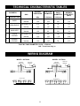
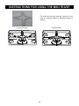
cooking collection
Instructions for use and warranty details
Gas Cooktop
Model No.: GCT600 and GCT900
2
Congratulations on the purchase
of your new Kleenmaid appliance.
Your new Kleenmaid appliance has been
designed and manufactured to give you
years of reliable performance.
For best results, carefully read the
instructions on how to install your new
appliance. Correct installation will avoid
delays and unnecessary service call costs.
Once installation is complete, please read
this entire instruction manual carefully and
get to know the controls and the features
of your new Kleenmaid appliance.
Again, congratulations and thank you for
choosing Kleenmaid.
3
THIS PRODUCT
IS DESIGNED FOR DOMESTIC USE.
THE
MANUFACTURER
DECLINESALL
RESPONSIBILITY FOR DAMAGES TO THINGS OR
PEOPLE DERIVING FROM INCORRECT
INSTALLATION OR IMPROPER, ERRONEOUS OR
UNSUITABLE USE.
THE APPLIANCE
MUST NOT BE USED BY PEOPLE
(INCLUDING CHILDREN) WITH PHYSICAL,
SENSORIAL OR MENTAL IMPAIRMENTS, OR BY PEOPLE
WITHOUT THE NECESSARY EXPERIENCE OR KNOWLEDGE,
UNLESS THEY ARE SUPERVISED OR INSTRUCTED IN THE USE
OF THE APPLIANCE BY A PERSON RESPONSIBLE FOR
THEIR SAFETY. CHILDREN MUST BE SUPERVISED TO
ENSURE THAT THEY DO NOT PLAY WITH THE APPLIANCE.
4
GENERAL NOTICE
We invite you to read this instruction booklet carefully, before installing and using the equipment.
It is very important that you keep this booklet together with the equipment for any future
consultation.
If this equipment should be sold or transferred to another person, make sure that the new
user receives the booklet, so that they can learn how to operate the appliance and read the
corresponding notice.
This is a Class 3 appliance.
This appliance complies with the following Directives:
EEC 2009/142/CE (Gas)
EEC 2006/95/CE (Low Voltage)
EEC 2004/108/CE (Electromagnetic Compatibility)
EEC 89/109 (Contact with foods)
WARNING
– The installation must be carried out by authorised personnel, in conformity with the regulations in force.
– CAUTION: The surface temperature of underbench components exceeds 95°C. To avoid a hazard,
underbench access must be restricted. Refer to the installation instructions.
– This appliance is not intended for use by persons (including children) with reduced physical, sensory or
mental capabilities, or lack of experience and knowledge, unless they have been given supervision or
instruction concerning use of the appliance by a person responsible for their safety.
– Children should be supervised to ensure that they do not play with the appliance.
– Before powering the equipment, check that it is properly adjusted for the type of gas at disposal (see the
“installation” paragraph).
–
– Before carrying out the maintenance or cleaning the equipment, cut off power supply and allow it cool
down.
– Make sure that air circulates around the gas equipment. Insufficient ventilation produces a lack of oxygen.
– In case of an intense or prolonged use of the equipment, it may be necessary to improve aeration, for
example by opening a window or increasing rangehood venting power, if it exists.
– The products of combustion must be discharged outside through a suction hood or an electric fan (see
the “installation” paragraph).
– For any possible operation or modification, apply to an authorized Technical Assistance Centre and
demand original spare parts.
–
– Not for use in marine craft, caravans or mobile homes unless each burner is fitted with a flame
safeguard.
–
–
DO NOT MODIFY THIS APPLIANCE.
Servicing shall be carried out only by authorised personnel.
The product label, with the serial number, is fixed to the underside of hob.
An additional label should be adhered to adjacent cabinetry for easy access- refer installation
instructions.
The manufacturer refuses all responsibility for possible damages to things or people, resulting
from incorrect installation or from an improper, incorrect or unreasonable use of this equipment.
1
INSTRUCTIONS FOR THE USER
It is necessary that all the operations regarding the installation, adjustment and
adaptation to the type of gas available are carried out by authorised personnel, in
conformity with the regulations in force. The specific instructions are described in the
booklet section intended for the installer.
Conditions of Use.
This appliance is intended to be used in household and similar applications such as:
- Staff kitchen areas in shops, offices and other working environments
- Farm Houses
- By clients in hotels, motels and other residential type environments
- Bed and breakfast type environment
It is important to use cookware with the sizes
specified and ensure the cookware is always
correctly centred over the burner. Using
oversize cookware can potentially cause heat
damage to your benchtop and/or control knobs
which will not be covered under warranty.
USING THE BURNERS
The symbols silk-screen printed on the side of the knob
indicate the correspondence between the knob and the
burner.
Automatic start-up with valves
Notice
– When the equipment is not working, always check that
the knobs are in the closing position (see fig.1).
– If the flame should blow out accidentally, the safety
valve will automatically stop the gas supply, after a
few seconds. To restore operation, set the knob to the
lighting point (large flame, fig. 1) and press.
– While cooking with fat or oil, pay the utmost attention as
these substances can catch fire when overheated.
– Do not place unstable or deformed pots on the burner,
so as to prevent them from overturning or overflowing.
– Handles should be turned away from the front of the
bench to avoid accidents.
– When the burner is started up, check that the flame is
regular and, before taking pots away, always lower the
flame or put it out.
1
6
ATTENTION: the triple ring burner switches on only in
the maximum flame position
Using the burners
In order to obtain the maximum yield without waste of
gas, it is important that the diameter of the pot is suitable
for the burner potential (see the following table), so as to
avoid that the flame going out (fig. 2).
Use the maximum capacity to quickly make liquids reach
boiling temperature, and the reduced capacity to heat
food or maintain boiling. All of the operating positions
must be chosen between the maximum and the minimum
ones, never between the minimum position and the
closing point.
The gas supply can be interrupted by turning the knob
clockwise up to the closing position. If there is no power
supply, it is possible to light the burners with matches,
setting the knob to the start-up point (large flame, fig. 1).
Power (MJ/h)
NG
LPG
Ø of
cookware
(*)
Auxiliary
32
3,4
10 - 14 cm
Semi-rapid
60
5,6
16 - 18 cm
Rapid
11,2
9,6
20 - 22 cm
Triple crown
10 8
10 4
24 - 26 cm
Double crown
10,3
9,6
20 - 22 cm
BURNERS
(*) For cookware with diameter 120mm or
below use mini-trivet supplied, refer
fitment instructions on page 1 .
2
INSTRUCTIONS FOR THE USER
1
2
3
4
Burner
Flame safeguard sensor (where fitted)
Injector
Ignition spark plug
If you have a problem with the cooktop, check the table below. You may be able to solve the problem and
this will save you from paying for a service call. You will have to pay for a service call even in the warranty
period if the problem is one listed below
FAULT
POSSIBLE CAUSES
REMEDY
Burner will not light
even though the
sparker is working.
Knob not held down long enough in Repeat lighting procedure and hold knob
‘High’ position for flame safeguard down for 6 seconds in ‘High’ position (refer
(where fitted) to engage
page 3)
Gas supply valve turned off
Turn on gas supply to appliance
Wrong knob turned
Ensure the knob you are turning
corresponds to the burner you want to light
Port blockage in ignition area
Ensure that ports in ignition area are clean
and dry
Ignition spark plugs wet or dirty
Dry or clean ignition spark plugs
No spark is obtained
when control knob is
activated
Electricity supply is disconnected or
switched off"
Switch on electricity or check fuses
Ignition spark plugs wet or dirty
Dry or clean ignition spark plugs
Flames uneven or
tending to lift
Flame ports blocked or wet
Clean or dry flame ports
Burner incorrectly fitted
Ensure this component is fitted correctly
Flames not staying on
when knob released
Knob not held down long enough
in ‘High’ position for flame safeguard
(where fitted) to engage
Repeat lighting procedure and hold knob
down for 6 seconds in ‘High’ position
(refer page 3)
Knob not set between ‘High’ and
‘Low’
Knob MUST be set between these
positions
Dirt or spillage on flame safeguard
sensor (where fitted)
Clean flame safe guard sensor tip
Low heat, slow
cooking
Incorrect cooking pot or pan being
used
Refer to table page 3
Benchtop or knobs
overheating
Incorrect cooking pot or pan used
Check table on page 3 for correct pot or
pan to be used
Pot or pan not located on burner
Ensure pot or pan is centrally located
properly
on burner
If the above points have been checked and there is still a problem with the cooktop, please call the
Service Centre.
norma peration
3
INSTRUCTIONS FOR THE USER
CLEANING
Wash with warm soapy water and rinse with clean water.
Where the stainless steel has become extremely dirty
with signs of surface discolouration (due to periods of
neglect or misuse) use a stainless steel cleaner
DO NOT use abrasive scourers or steel wool. When
removing these stains be sure to follow the polish of
brushing lines.
Before any operation, disconnect the appliance from
the electrical supply.
Don’t use a steam cleaner for the cleaning the hob.
It is advisable to clean the appliance when it is cold.
Enamelled parts
The enamelled parts must be washed with a sponge and
soapy water or with a light detergent.
Do not use abrasive or corrosive products.
Do not leave substances, such as lemon or tomato juice,
salt water, vinegar, coffee and milk on the enamelled
surfaces for a long time.
Burners and racks
These parts can be removed to make cleaning easier.
The burners must be washed with a sponge and soapy
water or with a light detergent, wiped well and placed in
ducts are not clogged. Check that the feeler of the safety
valve and the start-up electrode are always cleaned, so
as to ensure optimum operation.
The racks can be washed in the dishwasher.
Stainless steel parts
Gas taps
The possible lubrication of the taps must be carried out by
authorised personnel, exclusively.
In case of hardening or malfunctions in the gas taps,
apply to the Customer Service.
INSTRUCTIONS FOR THE INSTALLER
Important notice:
The operations indicated below must be followed by authorised personnel exclusively, in
conformity with the regulations in force.
The manufacturing firm refuses all responsibility for damages to people, animals or things,
resulting from the failure to comply with such provisions.
This appliance shall be installed only by authorised persons and in accordance with the
manufacturer’s installation instructions, local gas fitting regulations, municipal building codes,
electrical wiring regulations, and any other statutory regulations. For Australia and New Zealand
this appliance must be installed by an authorised person in compliance with AS/NZS 5601For
outside of Australia/New Zealand refer to the relevant installation code for gas appliances in
your country.
INSTALLATION
– For conversion to LPG
– 1 Universal LPG sticker
– 4 or 5 injectors
Additional accessory for cooking with vessels
diameter 120mm or below
– 1 mini trivet
The installation kit contains the following:
– 1 natural gas regulator
– 1 elbow
– 1 manifold
– 2 fibre sealing washers
– 4 brackets for assembly
– 4 bracket screws
– 1 pack of cooktop to benchtop seals
– 1 duplicate rating label
Installing the top
The appliance is designed to be embedded into heatresistant benchtop capable of withstanding 85°C.
4
INSTRUCTIONS FOR THE INSTALLER
Depending on the type of mounting surface, the
suitable type of mounting hook is supplied (hook A
or hook B).
For the installation proceed as follows:
– Remove all loose components from the top.
– Turn the appliance upside down lay it's edges on
foam packaging blocks to prevent damage to the
ignition spark plugs and lay the seal S along the
external border (fig. 5).
– Introduce and place the cook-top in the hole
made in the piece of furniture, then fasten it
with the screws and fastening brackets supplied
(fig.6).
Adjacent walls, cupboards and protection for
combustible materials.
Ensure that the appliance is installed in
accordance with of AS/NZS 5601 with regard to
clearances to combustible surfaces and
materials, and clearances to rangehoods and
exhaust fans.
Clearance of 200mm from the periphery of burners
to vertical combustible surfaces is required.
Clearances to combustible surfaces may be
reduced only if combustible surfaces are protected
in accordance with AS/NZS 5601
The equipment must not be installed near
inflammable materials, such as curtains,
cloths,etc. Make a cut out in the benchtop, with
the dimensions indicated in fig.3, at a distance of
at least 50 mm from the appliance border to the
adjacent walls.
MODEL
L (mm)
P (mm)
D (mm)
6020
560
480
55
9020
860
480
55
WARNING: Failure to fix the cooktop to the bench
could result in loosening of the gas connection
through movement of the cooktop and a gas leak
may result.
A duplicate rating label is included with these
instructions. Ensure this is attached to a readily
accessible surface, so that the cooktop can be
INSTALLATION ROOM
This appliance is not provided with a device for
exhausting the products of combustion.
Therefore, it is necessary to discharge these
outside.
The room where this appliance is installed
must have a natural air inflow, so as to ensure
a regular gas combustion and room ventilation:
the necessary air volume must not be lower than
20m3.
Air must come from permanent openings made on
the room walls that communicate with the outside.
The section of these openings shall correspond to
at least 200 cm2.
Any possible wall unit over the cook-top must be
placed at a distance of at least 760 mm from the
top.
IMPORTANT:
A separation panel at least 10mm from the
bottom of the cooktop must be included during
installation to prevent access to the underside
of the appliance. This panel can be made of any
non-combustible rigid material. Refer (fig. 4).
If the hob is going to be installed on the top of an
oven, precautions must be taken to guarantee an
installation in accordance with current accident
prevention standards. Pay particular attention to
the position of the electric cable and gas pipe: they
must not touch any hot parts of the oven.
Moreover, if the hob is going to be installed on
the top of a built in oven without forced cooling
ventilation, proper air vents must be installed to
guarantee an adequate ventilation, with the lower
air entering with a cross section of at least 200cm2,
and the higher air exiting with a cross section of at
least 60 cm2.
S
Regulator
An appliance regulator is provided. The regulator
must be positioned so that the pressure test nipple
is accessible when the appliance is installed.
Connect the gas supply to the 1/2" B.S.P. internal
thread inlet of the regulator. Refer to page 8 for
connection point position.
Regulators are supplied pre-adjusted and
configured by the component maker for use with
Natural Gas. The appliance installer is not required
to make an adjustment to obtain the correct outlet
pressure setting.
An arrow on the base of the regulator indicates
the direction of gas flow when the inlet and outlet
of the regulator is orientated correctly. When the
regulator has been fitted check for leaks from the
connections with soapy water.
Fastening the top
Every cook-top is equipped with a special washer.
A set of hooks is also supplied for mounting the
cook-top.
5
INSTRUCTIONS FOR THE INSTALLER
Gas Connection
Elbow positioning
It is possible to reposition the elbow if required by
loosening the locking nut and elbow by using two
spanners. Re-tighten the entire assembly after the
elbow has been repositioned. When fitting elbow to
appliance, ensure that the sealing washer is fitted.
This appliance is supplied for use with Natural
Gas. However, it can be converted for use
with LPG. Refer to LP conversion chapter.
5601
Regulator
An appliance regulator is provided. The regulator
must be positioned so that the pressure test nipple is
accessible when the appliance is installed. Connect
the gas supply to the ½” B.S.P. internal thread inlet
of the regulator. Refer page 10 for connection point
position.
31
1869
10
12
5601
Assembly of Regulator
The assembly of the regulator to the cooktop
manifold is achieved via the elbow union and
sealing washersupplied.
The ½” parallel thread connects to the manifold, and
the sealing washer is placed between the manifold
end and the flat face on the elbow.
The ½” tapered thread connects to the outlet of the
regulator, and is sealed on the thread using
approved thread sealing tape or approved thread
sealing compound.
The inlet of the regulator is a ½”
thread and is
connected to consumer piping or hose assembly.
Regulators are supplied pre-adjusted and
configured by the component maker for use with
Natural Gas.
The appliance installer is not required to make an
adjustment to obtain the correct outlet pressure
setting.
An arrow on the base of the regulator indicates the
direction of gas flow when the inlet and outlet of the
regulator is orientated correctly. When the regulator
has been fitted check for leaks from the connections
with soapy water.
Supply pipe sizing
The total hourly gas consumption for the appliance
is shown on the data label. The required supply
pressure (i.e. at inlet to appliance regulator) for
each gas type is shown on the data label, and
given in page "TECHNICAL CHARACTERISTIC
TABLES". Use this information in conjunction with
the length of run, number of elbows, tees and
bends, the available service pressure and the
supply requirements of other installed appliances
to determine a suitable pipe size. For assistance
in this matter refer to the appropriate section of the
Installation Code AS5601.
Checking the gas supply
1. Check the manometer zero point is correct.
2. Connect the manometer to the cooktop
pressure point. This is located on the
regulator.
3. Turn on the gas supply and electricity and try
to ignite the gas. NOTE! lt will take additional
time to light the gas for the first time as air
needs to be purged from the pipes.
4. With the appliance operating check the outlet
pressure
when all burners of the appliance are
operating at maximum,
when the smallest burner of the appliance is
operating at minimum.
An
ertified class B or D flexible
connection may be used to connect the cooktop in
accordance with the AS5601 and in particular
section 4.8. Where a hose assembly is used
and the cooktop is in the installed position, the
hose assembly shall be suitable for connection
to a fixed consumer piping outlet located at a
point 800 - 850mm above the floor and in the
region outside the width of the appliance to a
distance of 250mm. The point of connection to
consumer piping must be accessible with
appliance installed.
6
INSTRUCTIONS FOR THE INSTALLER
GAS CONVERSIONS AND ADJUSTMENTS
Under these conditions the outlet pressure should
not vary from the nominal outlet pressure of
1.00kPa by more than ± 0.20kPa
Data Label
This appliance is suitable for Natural Gas and
Universal LPG; ensure that the available gas supply
matches the Data Label.
When converting from Natural Gas to Universal
LPG ensure that the NG regulator is removed
and replaced with the Test Point Assembly. An
AGA Approved gas regulator suitable for a supply
pressure of 2.75kPa should be part of the gas
tank supply and the test point pressure should be
adjusted to 2.75kPa.
I f the re g u lat or a ppears t o n o t p e r fo r m
satisfactorily, then check the following points:
1. If the outlet pressure is consistently too low
then the inlet pressure may be too low and
adjustment of an upstream regulator may be
needed, or an upstream regulator or valve
with insufficient flow capacity may be present
in the gas supply line. If this is suspected then
it may be necessary to repeat fhe checks
whilst measuring both the inlet and outlet
pressure to determine if the inlet pressure is
in the range 1.13 - 5kPa.
2. Check that the regulafor has been fitted to the
gas supply line in the correct orientation, the
arrow on the base of the body indicates the
direction of gas flow.
Once these checks have been completed, if the
regulator still fails to perform in a satisfactory
manner it should be replaced.
Replacing the injectors
If the equipment is adjusted for a type of gas that is
different from the one available, it is necessary to
replace the burner injectors.
The choice of the injectors to replace must be
made according to the table of the “technical
characteristics” as enclosed.
Act as follows:
– remove the racks and burners.
– by means of a straight spanner L, unscrew
the injectors U (fig. 7) and substitute it with the
corresponding one.
– tighten the injectors strongly.
Electrical connection
The appliance is supplied with a standard 10
Amp service cord terminated by a 3-pin plug for
After changing the injectors, it is necessary to
eliminate residual natural gas in the system.
To do this you have to turn to the maximum
position then press the knob of each burner and
wait few seconds.
connection to a standard household socket. The
electrical supply is required to power the electronic
ignition system.
NOTE: It will be necessary for servicing purposes
to disconnect the electrical power supply. The
power point should therefore be accessible after
the appliance is
installed, as specified in the local wiring
regulations.
Adjusting the burners
The lowest flame point must always be properly
adjusted and the flame must remain on even if
there is an abrupt shift from the maximum to the
minimum position.
If this is not so, it is necessary to adjust the lowest
flame point as follows:
– start the burner up
– turn the tap up to the minimum position (small
flame)
– remove the knob from the tap rod
– introduce a flat-tip screwdriver in the hole F of the
tap (fig. 8) and turn the by-pass screw up to a
proper adjustment of the lowest flame point.
As regards U-LPG gas burners, the by-pass
screw must be tightened completely.
TESTING APPLIANCE OPERATION
After installation the installer must fully test the
appliance and ensure it operates correctly before
handing it over to the customer.
efore eaving
7
INSTRUCTIONS FOR THE INSTALLER
MAINTENANCE
Maintenance Schedule
No regular maintenance is required for the
hotplates except cleaning.
7
Replacing the power supply cable
If the power supply cable should be replaced,
it is necessary to use a cable with a section of
3x0.75mm2, type H05VV-F or H05RR-F, complying
with the regulations in force.
The connection to the terminal board must be
effected as shown in fig.9 - 9/A:
brown cable L
blue cable N
green-yellow cable
(phase)
(neutral)
(ground)
8
OFF
MAXIMUM
MINIMUM
1
2
3
4
5
6
F
7
8
9
9/A
9
Text
100
MODEL:
Depth of cooktop casing
from benchtop surface : 55mm
12
100
50
MODEL:
Depth of cooktop casing
from benchtop surface : 55mm
12
300
1 Rapid burner
2 Semi-rapid burner
3 Auxiliary burner
4 Triple ring burner
5 Double ring burner
8 Control knob for burner
NG
11,2 MJ/h
6.0 MJ/h
3.2 MJ/h
10 8 MJ/h
10.3 MJ/h
10
50
Universal LPG
9.6 MJ/h
5.6 MJ/h
3.4 MJ/h
10 4 MJ/h
9.6 MJ/h
TECHNICAL CHARACTERISTIC TABLES
NORMAL
PRESSURE
INJECTOR
DIAMETER
TAPE BY
PASS
DIAMETER
KPa
1/100 mm
1/100 mm
Universal LPG
2.75
85
42
9.6
Natural
1.00
152
38
11.2
Universal LPG
2.75
65
31
5.6
Natural
1.00
110
38
60
Universal LPG
2.75
52
27
3.4
Natural
1.00
80
38
3.2
BURNERS
GAS
NOMINAL
HEAT INPUT
(MJ/h)
N°
DESCRIPTION
1
RAPID
2
SEMI-RAPID
3
AUXILIARY
4
TRIPLE
CROWN
Universal LPG
2.75
90
60
10 4
Natural
1.00
150
112
10 8
5
DOUBLE
CROWN
Universal LPG
2.75
85
60
9.6
Natural
1.00
145
78
10.3
SS
-
mm
rns from f
in
WIRING DIAGRAM
MODEL:
MODEL:
IGNITION
GENERATOR
TRIPOLAR
TERMINAL
IGNITION
GENERATOR
MICRO-UNIT
MICRO-UNIT
11
TRIPOLAR
TERMINAL
INSTRUCTIONS FOR USING THE MINI TRIVET
The mini-trivet included with this cooktop is to be
used for cooking vessels of diameter 120mm or
smaller
Incorrect fitment
Correct fitment
12
Warranty and Service
Domestic Warranty – Full three year warranty
In addition to all statutory rights which you, the Purchaser, have under relevant laws in respect of
this appliance, during the first three years of ownership as the original purchaser of this Kleenmaid
appliance, Compass Capital Services trading as Kleenmaid guarantee that any fault caused by
defective material or workmanship becoming apparent will be rectified free of charge with reference
to parts and labour, provided that all service is performed during normal working hours by Kleenmaid
or their designated Agents. Where the appliance is installed outside the normal servicing area of the
above, the Purchaser must pay for the cost of transporting the appliance to and from the Agent or the
Agent’s travel cost to and from the purchaser’s home.
Commercial Warranty – One year warranty
When this appliance is installed in a commercial application, in addition to all statutory rights which
you, the Purchaser, have under relevant laws in respect of this appliance, during the first one year of
ownership as the original purchaser of this Kleenmaid appliance, Compass Capital Services trading as
Kleenmaid guarantee that any fault caused by defective material or workmanship becoming apparent
will be rectified free of charge with reference to parts and labour, provided that all service is performed
during normal working hours by Kleenmaid or their designated Agents. Where the appliance is installed
outside the normal servicing area of the above, the Purchaser must pay for the cost of transporting the
appliance to and from the Agent or the Agent’s travel cost to and from the purchaser’s home.
What these warranties do not cover
Compass Capital Services trading as Kleenmaid is not responsible for any damage or malfunction
unless caused by a defect in material or workmanship. This includes but is not limited to abuse,
misuse, improper installation and transportation damage. Compass Capital Services trading as
Kleenmaid is not responsible for consequential damages from any malfunction.
This warranty does not cover wear or breakage of consumable items such as door seals , replacement
of light globes or glass breakage due to impact. In case of fractured glass do not use your appliance.
Purchaser’s responsibility
The Purchaser must make the appliance available for servicing and shall bear any costs incurred
for any de-installation and/or re-installation required to make the appliance available for servicing.
Compass Capital Services trading as Kleenmaid is not liable for any consequential damage incurred
during de-installation or re-installation.
Warranty registration and Proof of Purchase.
Please complete warranty details below and retain together with your proof of purchase document.
When requesting service under this warranty the Purchaser agrees that Proof of Purchase of their
Kleenmaid appliance will be necessary in order to make the warranty valid. Inability to provide Proof
of Purchase even though this warranty is in place will not bind Compass Capital Services trading as
Kleenmaid to repair the appliance at no charge under this warranty and will require the Purchaser to
pay for the service costs in full.
Model Number
For service assistance visit
www.kleenmaidhelp.com.au
Date of purchase
Other products available in the
Kleenmaid range of appliances
|
Washing machines
|
Clothes dryers
|
Dishwashers
|
Ovens
|
Cooktops
|
Steam ovens
|
Microwave ovens
|
Built in espresso
coffee machines
|
Rangehoods
|
Freestanding PWFO
Compass Capital Services Pty Limited
trading as Kleenmaid
ABN 96138214525
Level 2,
204 Botany Rd
Alexandria NSW 2015
E: [email protected]
www.kleenmaid-appliances.com.au