1
Encore
Woodburning Stove
Model 2550CE
Homeowner’s
Installation and
Operating Manual
For use in Europe
0956
Encore Cover
2/01
SAFETY NOTICE: IF THIS APPLIANCE IS NOT PROPERLY INSTALLED, OPERATED AND MAINTAINED, A HOUSE FIRE MAY RESULT.
TO REDUCE THE RISK OF FIRE, FOLLOW THE INSTALLATION INSTRUCTIONS. FAILURE TO
FOLLOW INSTRUCTIONS MAY RESULT IN PROPERTY DAMAGE, BODILY INJURY OR EVEN
DEATH. CONTACT LOCAL BUILDING OFFICIALS ABOUT RESTRICTIONS AND INSTALLATION
INSPECTION REQUIREMENTS IN YOUR AREA.
Do Not Discard This Manual: Retain for Future Use
30003842 2/08 Rev. 1
Downloaded from www.Manualslib.com manuals search engine
Encore Woodburning Stove
Welcome
Congratulations on your choice of a Vermont Castings Encore. With this purchase you have made a commitment to
make the hearth a place of warmth, beauty, and comfort in your home. At CFM Corporation, we share that joy and
appreciation for the hearth. You may be assured that your cast-iron Vermont Castings stove has been made with the
utmost care and will provide you with many years of service.
As you become acquainted with your new stove or fireplace, you will find that its visual appearance is matched by its
functionality, due to cast iron’s unique capability to absorb and radiate heat.
Also, CFM Corporation units are among the cleanest-burning wood stoves and fireplaces available today. As an owner
of a Vermont Castings stove, you make a strong statement for pollution-free energy. Clean burning, however, depends
on both the manufacturer and the operator. Please read this manual carefully to understand how to properly operate
and maintain your stove or fireplace.
At CFM Corporation, we are equally committed to your satisfaction as a customer. That is why we maintain an exclusive network of the finest dealers in the industry. Our dealers are chosen for their expertise and dedication to customer service. They are factory-trained and knowledgeable about every CFM Corporation product. Feel free to contact
your Authorized Vermont Castings Dealer anytime you have a particular question about your stove or its performance.
This manual contains valuable instructions on the installation and operation of your Vermont Castings stove. It also
contains useful information on maintenance and assembly of this product. We urge you to read the manual thoroughly
and to keep it as a reference.
Sincerely,
All of us at CFM Corporation
This manual describes the installation, operation, and
maintenance of the Vermont Castings Encore Model
2550CE catalytic-equipped wood burning heater. This
heater meets the U.S. Environmental Protection Agency’s emission limits for wood heaters sold on or after
July 1, 1990. Under specific test conditions this heater
has been shown to deliver heat up to 10.1 kW (34,500
BTU/hr).
The Encore Model #2550CE has been tested to current standards. The test standards are UL-1482 and
ANUL-737 for the United States, and EN13240:2001
+ A2:2004 for Europe. The Encore is listed for burning
wood. Do not burn other fuels. The Encore is listed
and approved for use in mobile homes in the United
States only when installed with Vermont Castings Mobile Home Kit #3251.
We recommend that you hire a professional installer
install your stove, or to advise you on the installation
should you attempt to install it yourself.
Please read this entire manual before you install and
use your new stove. Failure to follow instructions may
result in property damage, bodily injury, or even death.
2
Downloaded from www.Manualslib.com manuals search engine
Table of Contents
Specifications ....................................... 3
Installation ............................................ 4
Assembly ............................................ 12
Operation ............................................ 13
Draft Management .............................. 19
Maintenance ....................................... 21
Appendix: Catalytic Combustor .......... 27
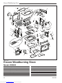
Replacement Parts ............................. 28
Warranty ............................................. 31
Accessories
Warming Shelves
#1560 Classic Black
#1562 Sand
#1555 Biscuit
#1565 Bordeaux
#1556 Chestnut Brown
#1566 Forest Green
#1557 Ebony
#1567 Midnight Blue
#1558 Vt. Classic Green #1568 Suede Brown
# 0164 Bottom Heat Shield
# 0173 Rear Heat Shield
# 3257 Outside Air Adapter
# 3251 Mobile Home Kit
# 0191 Heat shields for the chimney connector
- Matching porcelain stovepipe
30003842
Encore Woodburning Stove
Specifications
Encore Model 2550CE
Nominal heat out put ............10.1 kW (34,500 BTU/hr)1
Minimum flue draught ......................12 Pa (0.048” WG)
Mean flue gas temp .............................. 339° C (642° F)
Efficiency (Space heating) ......................................75%
Area heated ................... Up to 175 sq. m (1900 sq. ft.)1
Fuel size/type .................... 457-510 mm (18-20”) wood
Flue mass gas flow ............................................. 8.3 g/s
CO Emissions (@ 13% O2) ........................... 1600 ppm
Loading .....................................................Front and top
Chimney connector:
for 8” flue collar ....................... 203 mm (8”) diameter
for 6” flue collar ....................... 152 mm (6”) diameter
Chimney flue size:
for 8” flue collar .......................203 mm (8”) minimum
for 6” flue collar .......................152 mm (6”) minimum
Flue exit position ....................... Reversible, top or rear
Primary air ... Manually set, thermostatically maintained
Secondary air .........................................Self-regulating
Ash handling system ..................... Removable ash pan
Glass panel ......................... High-temperature ceramic
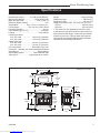
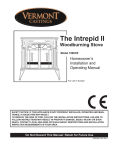
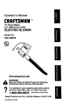
Weight ................................................ 159 kg (350 lbs.)
Width (leg-to-leg) ..................................... 685 mm (27”)
Depth (leg-to-leg) .................................... 380 mm (15”)
Height to top of flue collar, 152 or 203 mm (6” or 8”)
Top exit .............................................. 640 mm (25¹⁄₄”)
Rear exit ............................................ 675 mm (26¹⁄₂”)
1. This value can vary depending on how the stove
is operated, the type and moisture content of the fuel
used, as well as the design, construction and climatic
location of your home. Figures shown are based on
nominal fuel consumption obtained under laboratory
conditions and on average efficiencies.
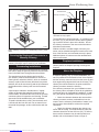
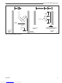
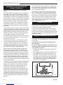
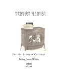
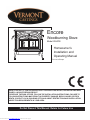
Drawings Not to Scale
460 mm (18")
83 mm
(3���")
545 mm
(21���")
610 mm
(24")
690 mm (27")
51 mm
(2")
390 mm
(15���")
685 mm (27”)
470 mm
(18���")
570 mm (22���")
640 mm
(25���")
Top exit
flue collar
height
660 mm
(25���")
130 mm
(5")
75 mm (2���")
595 mm
(23���")
190 mm
(7���")
135 mm
(5���")
685 mm (27")
380 mm
(15")
Fig. 1 Encore dimensions.
30003842
Downloaded from www.Manualslib.com manuals search engine
����
Encore 2550 EU
dimensions
8/06
3
Encore Woodburning Stove
Installation
Before you begin an installation, be sure that:
• Your stove and chimney connector will be far
enough from combustible materials to meet all
clearance requirements.
• The floor protector is large enough and is constructed properly to meet all requirements.
• You have all necessary permits from local authorities.
Your local building official is the final authority for approving your installation as safe and determining that it
meets local and state codes.
The metal label permanently attached to the back of
every Vermont Castings’ stove indicates the stove has
been tested to current standards. The test standard
is EN13240:2001 + A2:2004 for Europe. Clearance
and installation information also is printed on the label.
When the stove is installed according to the information
both on the label and in this manual, local authorities
in most cases will accept the label as evidence that the
installation meets codes and can be approved.
However, codes vary in different countries. Before
starting the installation, review your plans with the local
building authority. Your local dealer can provide any additional information needed.
IMPORTANT: FAILURE TO FOLLOW THESE INSTALLATION INSTRUCTIONS MAY RESULT IN A
DANGEROUS SITUATION, INCLUDING A CHIMNEY
OR HOUSE FIRE. FOLLOW ALL INSTRUCTIONS
EXACTLY, AND DO NOT ALLOW MAKESHIFT COMPROMISES TO ENDANGER PROPERTY AND PERSONAL SAFETY.
All local regulations, including those referring to
national and European standards, need to be complied with when installing this stove.
Outside Air
In some modern, super-insulated homes, there is
inadequate air for combustion because of insufficient
air infiltration into the building. Such air enters a home
through unsealed cracks and openings. Exhaust fans
for kitchen or bath can compete with the stove for available air and compound the problem.
When poor draft is caused by a low infiltration rate,
opening a ground floor window on the windward side
of the house and in the vicinity of the stove will usually
alleviate the problem.
For appliances with power outputs above 5 kW, a
permanently open air vent is required by Section 2 of
Document J. Air inlet grilles should be positioned so
that they will not be blocked. Refer to local and national
codes for recommended configurations.
Pressure variations within the house do not affect a
stove equipped with an outside air supply, and improved stove performance often results. An Outside Air
Adapter Kit for the Encore is available from your local
Vermont Castings dealer.
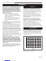
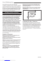
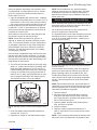
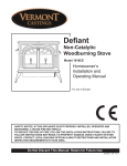
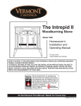
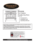
Chimney Height
Altitude affects chimney performance. When using a
6” flue collar on the Encore, refer to Figure 2 for suggested chimney heights at various altitudes. Chimney
height should be measured from the flue collar to the
top of the chimney. The recommended minimum chimney height is 4.9 m (16’).
30
25
Height
SAFETY NOTICE: IF YOUR ENCORE IS NOT PROPERLY INSTALLED, A HOUSE FIRE MAY RESULT.
TO REDUCE THE RISK OF FIRE, FOLLOW THE
INSTALLATION INSTRUCTIONS. CONTACT LOCAL
BUILDING OR FIRE OFFICIALS ABOUT RESTRICTIONS AND INSTALLATION INSPECTION REQUIREMENTS IN YOUR AREA.
20
15
0
ST491
2000
4000
6000
8000
10000
12000
Altitude
Fig. 2 Chimney height requirements for Encore when
equipped with a 152 mm (6”) chimney.
4
Downloaded from www.Manualslib.com manuals search engine
ST491
Defiant
chimney height
11/2/00 djt
30003842
Encore Woodburning Stove
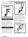
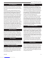
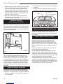
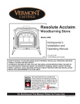
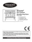
What Kind of Chimney to Use
You must connect the Encore to a code-approved
masonry chimney with a flue liner, to a relined masonry
chimney that meets local codes, or to a prefabricated
metal chimney. (Fig. 3) The chimney and chimney connector must be in good condition and kept clean.
If you use an existing masonry chimney, it must be
inspected to ensure it is in a safe condition before the
stove is installed. Your local professional chimney
sweep, building inspector, or fire department official will
be able to inspect the chimney or provide a referral to
someone who can.
The flue and chimney design must meet requirement
J2, Part J of the building regulations 2000 (Combustion
Appliances and Fuel Storage Systems).
A prefabricated doublewall insulated chimney
Prefabricated Chimneys
These should be an internal diameter of 150 mm (6”)
and be of the twin wall insulated construction that has
been approved for solid fuel use (e.g. Rite Vent ICS of
ICID Lite Chimney Systems). Diameters over 200 mm
(8”) are not recommended due to the large cross-section causing excessive cooling of the flue gases.
DO NOT CONNECT THIS UNIT TO A CHIMNEY FLUE
SERVING ANOTHER APPLIANCE.
Chimney Size
An Encore with an 203 mm (8”) flue collar is approved
for venting into a masonry chimney with a nominal flue
size of 203 x 203 mm (8” x 8”) or 203 x 305 mm ( 8”
x 12”), and into a round flue with nominal flue size of
203 mm (8”). An Encore with a 152 mm (6”) flue collar
is approved for venting into a masonry chimney with a
nominal flue size of 203 x 203 mm (8” x 8”), and into a
round flue with nominal flue of 152 mm (6”).
NOTE: When installed with a 6” flue collar, the
Encore may not be operated with the front doors
open.
A tile-lined
masonry
chimney
ST241
Fig. 3 Approved chimney types.
Masonry Chimneys
An inspection of the chimney
ST241 must confirm that it has
types chimney. The chimney
a lining. Do not usechimney
an unlined
12/13/99 djt
should have no cracks, loose mortar, other signs of
deterioration, and blockage. Repair any defects before
the chimney is used with your stove.
Unused openings in an existing masonry chimney must
be sealed with masonry to the thickness of the chimney
wall, and the chimney liner should be repaired. Openings sealed with pie plates or wallpaper are a hazard
and should be sealed with mortar or refractory cement.
In the event of a chimney fire, flames and smoke may
be forced out of these unused thimbles.
The chimney should be thoroughly cleaned before use.
A newly-built masonry chimney must conform to the
standards of your local building code or, in the absence
of a local code, to a recognized national code. Masonry
chimneys must be lined, either with code-approved
masonry or pre-cast refractory tiles, stainless steel
pipe, or a code-approved, “poured-in-place” liner. The
chimney’s clean-out door must seal tightly.
30003842
Downloaded from www.Manualslib.com manuals search engine
Whatever the flue collar size, an Encore may be vented
into larger chimneys as well. However, chimneys
with liners larger than 203 x 305 mm (8” x 12”) may
experience rapid cooling of smoke and reduction in
draft, especially if the chimneys are located outside the
home. These large chimneys may need to be insulated
or have their flues relined for proper stove performance.
Accessories to help make the connection between
stainless steel chimney liners and your Encore are
available through your local dealer.
Chimney Connector Guidelines
A chimney connector is the double-wall or single-wall
pipe that connects the stove to the chimney. The chimney itself is the masonry or prefabricated structure that
encloses the flue. Chimney connectors are used only to
connect the stove to the chimney, as in Figure 5.
Connecting Flue Pipes
Connector pipes should meet the requirements of the
building regulations. This can be achieved by the use
connecting fluepipes included in the following categories:
a) Vitreous enamelled steel pipe complying with BS
6999: 1989 (1996);
b) Pipes made from stainless steel as descirbed in BS
EN 1008-1:1995 grades 1.4401, 1.4404, 1.4432 or
1.4436 with flue wall thickness of at least 1 mm;
c) Mild steel fluepipes complying with BS 1449: Part 1:
1991, with a flue wall thickness of at least 3 mm;
d) Cast iron fluepipes complying with BS 41: 1973
(1998).
5
Encore Woodburning Stove
Flue Pipes with a spigot and socket joint should be
fitted with the socket facing upwards, to contain condensates and moisture within the flue. Joints should be
made gas tight using proprietary jointing accessories,
or, where appropriate, by packing joint with noncombustible rope and fire cement.
Double-wall connectors must be tested and listed for
use with solid-fuel burning appliances. Single-wall connectors should be made of 24 gauge or heavier steel.
Do not use galvanized connector; it cannot withstand
the high temperatures that can be reached by smoke
and exhaust gases, and may release toxic fumes under
high heat. The connector may be 152 mm (6”) or 203
mm (8”) in diameter.
If possible, do not pass the chimney connector through
a combustible wall or ceiling. If passage through a combustible wall is unavoidable, refer to the section on Wall
Pass-Throughs. Do not pass the connector through an
attic, a closet or similar concealed space. The whole
connector should be exposed and accessible for inspection and cleaning.
In horizontal runs of chimney connector, maintain a distance of 610 mm (24”) from the ceiling. Keep it as short
and direct as possible, with no more than two 90° turns.
Slope horizontal runs of connector upward 6 mm per
metere (1/4” per foot) going from the stove toward the
chimney. The recommended maximum length of a horizontal run is 914 mm (36”), and the total length should
be no longer than 2.4 m (8’). In cathedral ceiling installations, extend the prefabricated chimney downward to
within 2.4 m (8’) of the stove.
Wear gloves and protective eyewear when drilling,
cutting or joining sections of chimney connector.
Double-wall Chimney Connectors
Information on assembling and installing double-wall
connectors is provided by the manufacturer of the
double-wall pipe. Follow the manufacturer’s instructions
exactly as you assemble the connector and attach it to
the stove and chimney. Using chimneys and connectors
from the same manufacturer makes the assembly and
installation straightforward.
NOTE: For installations using double-wall connectors,
minimum clearances must conform to the listed clearances in the clearance chart on Page 14.
If the Encore is equipped with the 203 mm (8”) flue
collar, an oval-to-round adapter will be needed. Doublewall oval-to-round adapters are available from some
manufacturers. Your local dealer can help you select
the right connector.
6
Downloaded from www.Manualslib.com manuals search engine
Single-wall Chimney Connectors
• Begin assembly at the flue collar of the stove. Insert
•
•
•
the first crimped end into the stove’s flue collar, and
keep each crimped end pointing toward the stove.
(Fig. 4) Using the holes in the flue collar as guides,
drill 3 mm (1/8”) holes in the bottom of the first section of chimney connector and secure it to the flue
collar with three #10 x 1/2” sheet metal screws.
Secure each joint between sections of chimney
connector, including
telescoping joints, with at
least three (3) sheet metal
screws. The pre-drilled
holes in the top of each
section of chimney connector serve as guides
when you drill 3 mm (1/8)
holes in the bottom of the
next section.
Secure the chimney conFig. 4 the crimped end
nector to the chimney.
of the connector points
Instructions for various
ST242
connector
towardChimney
stove.
installations follow.
12/13/99 djt
Be sure the installed stove
and chimney connector are correct distances from
nearby combustible materials.
NOTE: Special slip pipes and thimble sleeves that form
telescoping joints between sections of chimney connector are available to simplify installations. They often
eliminate the need to cut individual connector sections.
Consult your local dealer about these special pieces.
Securing the Single-wall Connector to a
Prefabricated Chimney
Follow the installation instructions of the chimney
manufacturer exactly as you install the chimney. The
manufacturer of the chimney will supply the accessories to support the chimney, either from the roof of
the house, at the ceiling of the room where the stove is
installed, or from an exterior wall.
Special adapters are available from your local dealer
to make the connection between the prefabricated
chimney and the chimney connector. The top of such
adapters attaches directly to the chimney or to the
chimney’s ceiling support package, while the bottom of
the adapter is screwed to the chimney connector.
These adapters are designed so the top end will fit
outside the inner wall of the chimney, and the bottom
end will fit inside the first section of chimney connector.
When assembled in this way, any soot or creosote falling from the inner walls of the chimney will stay inside
the chimney connector.
30003842
Encore Woodburning Stove
Chimney
Flue
Elbow
Thimble Sleeve
Flue Liner
Chimney Connector
Keep
sleeve
end flush
with flue
tile
Slip Pipe
Thimble
Standard
Connector
Oval to
Round Adapter
Flue
ST243
Flue Collar
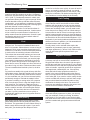
Fig. 6 The thimble, made of either ceramic or metal, must be
cemented securely in place.
ST492
Fig. 5 Chimney connection in a freestanding masonry installation.
Securing
ST492
Defiant
the Single-wall
freestanding Connector
installation
Masonry
Chimney
11/00
to a
Both freestanding masonry chimneys and fireplace
masonry chimneys may be used for your installation.
Freestanding Installations
If the chimney connector must pass through a combustible wall to reach the chimney, follow the recommendations in the Wall Pass-Through section that follows.
The opening through the chimney wall to the flue
(the “breech”) must be lined with either a ceramic or
metal cylinder, called the “thimble”, which is cemented
securely in place. Most chimney breeches incorporate
thimbles, but the fit must be snug and the joint between
the thimble and the chimney wall must be cemented
firmly.
A special piece called the “thimble sleeve,” slightly
smaller in diameter than standard connectors and
most thimbles, will facilitate the removal of the chimney
connector system for inspection and cleaning. Thimble
sleeves should be available from your local dealer.
To install a thimble sleeve, slide it into the breech until
it is flush with the inner flue wall. Do not extend it into
the actual flue passage, as this could interfere with the
draft.
30003842
Downloaded from www.Manualslib.com manuals search engine
The thimble sleeve should protrude 1-2” (25-50mm) into
the room. (Fig. 6) Use furnace cement and thin gasketing to seal the sleeve in place in the thimble. Secure
ST243
the chimney connector
to the outer end of the sleeve
thinble connection
with sheet metal12/13/99
screws. djt
Without a thimble, a suitable length of chimney connector can be extended through the breech to the inner
face of the flue liner, and cemented securely in place.
Additional pieces of connector are then attached with
sheet metal screws.
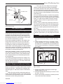
Fireplace Installations
The chimney connector may be connected to the
chimney above the fireplace opening or through the
fireplace.
Above the Fireplace
The Encore may be connected to a chimney above
a fireplace opening. (Fig. 7) In such installations, the
stove is positioned on the hearth in front of the fireplace
and the chimney connector rises from the stove top and
then angles ninety degrees back into the chimney. The
chimney liner should extend to the point at which the
chimney connector enters the chimney.
If the chimney connector from your installation enters
the chimney above a fireplace, follow all the guidelines
mentioned above for freestanding installations. In addition, give special consideration to the following points:
• Check the clearance between the stove and the
chimney connector, and any combustible trim or the
mantel. Use the necessary combination of mantel, trim,
and connector heat shields to achieve the required
clearances.
• Check the clearance between the chimney connector and the ceiling. If no heat shields are used, the
clearance should be at least 610 mm (24”). To find out
how much this clearance may be reduced with heat
shields, refer to the clearance chart on Page 12.
7
Encore Woodburning Stove
• The fireplace damper must be sealed to prevent
room air from escaping up the flue. However, it must be
possible to re-open the damper to inspect or clean the
chimney.
Flexible Connector
Chimney
Connector Shields
*
Mantel Shield
Fireplace Adapter
Kit “Positive Connection”
*
* Check
These Clearances
Mantel
Seal this off
ST244
Fig. 7 In this installation, the chimney connector is attached
to the chimney above the fireplace opening.
ST244
Through
the Fireplace
Plymouth
over mantel
If your fireplace openingfplc
height
is at least 675 mm (26¹⁄₂"),
12/99
you may install an Encore through the opening using a
“positive connection” kit, available from your local dealer.
These positive connection kits ensure a tight fit between
the stove flue collar and the chimney flue. (Fig. 8)
Fireplace installations, whether connected to the flue
above or through the fireplace opening, have special
clearance requirements to adjacent trim and the mantel.
You’ll find the required safe clearances for Encore fireplace installations on Page 11.
ST245
Fig. 8 In this installation, the chimney connector enters the
firepalce opening and then connects to the chimney.
ST245 of passing a connector
Figure 9 shows one method
fireplace material in the wall is cut
through a wall. All combustible
flex connector
away to provide the required
457 mm (18”) clearance
12/99
for the connector. The resulting space must remain
empty. A flush-mounted sheet metal cover may be used
on one side only. If covers must be used on both sides,
each cover must be mounted on noncombustible spacers at least 25 mm (1”) clear of the wall.
Your local dealer or your local building inspector can
provide details for other approved methods of passing
a chimney connector through a combustible wall in your
area.
DO NOT CONNECT AN ENCORE TO ANY AIR DISTRIBUTION DUCT OR SYSTEM.
457 mm (18”) clear
space all around
the pipe
Floor protection requirements also apply to fireplace
installations. This information is on Page 9.
Wall Pass-Throughs
Whenever possible, design your installation so the connector does not pass through a combustible wall. If you
are considering a wall pass-through in your installation,
check with your building inspector before you begin.
Also, check with the chimney connector manufacturer
for any specific requirements.
Accessories are available for use as wall passthroughs. If using one of these, make sure it has been
tested and listed for use as a wall pass-through.
8
Downloaded from www.Manualslib.com manuals search engine
T
ST494
Fig. 9 An approved wall pass-through.
ST494
steel
wall pass thru
11/00
30003842
Encore Woodburning Stove
Hearths
This appliance must be installed on to hearth that
meets the requirements of Part J of the Building Regulations 2000 (Combustion Appliances and Fuel Storage
Systems). This can be achieved by ensuring that the
hearth is constructed and sized in accordance with the
guidelines included in section 2 of approved document
‘J’. The size and clearances of the hearth are as follows:
The constructed hearth should be constructed in accordance with the recommendations in document J,
and should be of minimum width 840 mm and minimum
depth 840 mm (if a free standing hearth b) above) or
a minimum projection of 150 mm from the jamb (if a
recessed hearth a) above).
Unless the stove
hearth is completely
noncombustible, the
bottom heat shield
should be installed to
provide radiant protection for framing which
may be below the
hearth. (Fig. 11)
Wood framing requires protection from radiant heat
ST247e
Fig. 11 Combustible supporting timbers may lie beneath
fireplace hearths, requiring additional floor protection.
Costructional Hearth
Dimensions as below
At least 150 mm
or to a suitable
heat resistant wall
Appliance
Appliance
Doors
ST247
Rear exit floor dgrm
12/14/99 djt
Doors
Hearth Surface
Free of Combustible Material
At least
150 mm
Perimeter should be
clearly marked e.g.
edge of superimposed
hearth
At least
300 mm
a) Fireplace recess
Perimeter should be
clearly marked e.g.
edge of superimposed
hearth
b) Free standing
ST912
Fig. 10 Noncombustible hearth surface dimensions.
Floor Protection for Fireplace Installations
Do not assume that your fireplace hearth is completely
noncombustible.
Many fireplace hearths do not meet the “completely
noncombustible” requirement because the brick or
concrete in front of the fireplace opening is supported
by heavy wood framing. (Fig. 11) Because heat passes
through brick or concrete readily, it can easily pass
through to the wood. As a result, such fireplace hearths
can be a fire hazard and are considered a combustible
floor.
Keep in mind, also, that many raised hearths will extend
less than the required clearance from the front of the
heater when it is installed. In such cases, sufficient
floor protection as described above must be added in
front of the hearth to satisfy the minimum floor protector
requirement from the front of the stove: 406 mm (16”)
from the front.
30003842
Downloaded from www.Manualslib.com manuals search engine
Hearth rugs do not satisfy the requirements for floor
protection.
Keep the Stove a Safe Distance
from Surrounding Materials
Both a stove and its chimney connector radiate heat in
all directions when operating, and dangerous overheating of nearby combustible materials can occur if they
are too close to the heat. A safe installation requires
that adequate clearance be maintained between the
hot stove and its connector and nearby combustibles.
Clearance is the distance between either your stove
(measured from the bottom edge of the stove’s top
plate) or chimney connector, and nearby walls, floors,
the ceiling, and any other fixed combustible surface.
Your stove has special clearance requirements that
have been established after careful research and testing to both US and European standards. These clear9
Encore Woodburning Stove
ance requirements must be strictly observed.
In addition, furnishings and other combustible materials
must be kept away from the stove as well. In general, a
distance of 1219 mm (48”) must be maintained between
the stove and moveable combustible items such as drying clothes, furniture, newspapers, firewood, etc. Keeping those clearance areas empty assures that nearby
surfaces and objects will not overheat.
Minimum side clearance from combustible walls
610 mm (24”) measured from the side edge of the
stove top. (Fig. 12, A)
Minimum distance from stove to movable combustible materials (e.g. furniture, drying clothes, etc.)
1220 mm (48”).
Safe Ways to Reduce Clearances
Clearances
As with any solid fuel heating stove, extremely high
surface temperatures can occur, particularly in the
event of uncontrolled operation, e.g. if the doors
are inadvertently left open. It is crucial that sufficient clearances are allowed to any combustible
surfaces, e.g. wooden mantels or lintels, and to
timber framed (studded) walls even if they are faced
with noncombustible board. Detailed information
on fireplace and hearth construction is provided
in section 2 of Document J, all installations must
comply with these requirements or with the relevant
National or local building standards.
Clearances to timber framed (studded) walls are included below. There are no specific minimum clearances to solid noncombustible surfaces (e.g. the sides and
rear of Inglenook fire openings constructed from solid
masonry) other than to allow safe access to the controls
of the stove. For this reason minimum side clearances
of 125 mm, and a minimum rear clearance of 50 mm
are recommended.
B
A
ST486a
Fig. 12 Minimum clearances.
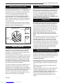
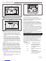
Connecting Flue Pipe - Clearances
ST486a
Single wall connecting fluepipes can reach extremely
Defiantclearances
EU
high temperatures; therefore,
from the connecting fluepipe (chimney
connector) must comply with
Clearance
the requirements of Part
J of Building Regulations 2000
Diagrams
(Combustion Appliances and Fuel Storage Systems).
10/06
This can be achieved by following the recommendations of Approved Document ‘J’. These are as shown in
Figure 13.
Summary of Clearances
Minimum recommended side clearances to noncombustible surfaces 125 mm (5”).
Minimum recommended rear clearance to noncombustible surfaces 50 mm (2”).
NOTE: The minimum thickness of solid noncombustible
materials is specified in section 2 of Document ‘J’, in
relation to the clearance of the appliance from the surface. As a general rule, the thickness of solid noncombustible material forming the recess of a fireplace is a
minimum of 200 mm.
Minimum rear clearance from combustible walls
(e.g. timber framed or studded walls) 1000 mm
(39³⁄₈”) measured from the rear edge of the stove
top. (Fig. 12, B)
10
Downloaded from www.Manualslib.com manuals search engine
30003842
Encore Woodburning Stove
at least
3xD
at least 3 x D
D
at least
1.5 x D
D
at
3 lea
x st
D
at least
1.5 x D
Fluepipe
at least
1.5 x D
at least
1.5 x D
at least 1.5
xD
Elevation
Without
Shield
Plan Without
Shield
Elevation
With Shield
Air space of at least 12 mm
between noncombustible shield
and combustible material
Plan With
Shield
ST911
Fig. 13 Connecting fluepipe clearances.
�����
�������������������
�����
30003842
Downloaded from www.Manualslib.com manuals search engine
11
Encore Woodburning Stove
Assembly
Adjust the Leg Levellers
Set Up Your Stove
Cast iron stoves are heavy, and it will take two to four
people to move your Encore into position.
Wipe the protective
coating of oil from
the griddle with a
clean dry rag or a
paper towel.
Lift the stove slightly so there is no weight on the leg
while making the adjustment.
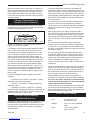
Reverse the Flue Collar (If Necessary)
Install the handle
on the griddle.
First, place the
griddle upside
ST516
down at the edge
Fig. 14 Attach the griddle handle.
of a flat surface and
assemble the handle as shown.
ST516
With the handle pointing 45° from its final
position,
Attach
tighten the nut as far as possible with griddle
the pliers.
Move
handle
the handle to its final position while still
holding
the
11/17/00 djt nut
with the pliers.
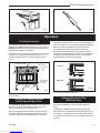
Reverse the flue collar by removing the two (2) screws
that attach it to the back of the stove. Be sure the gasket around the flue collar opening is in position when
you screw the collar back onto the stove.
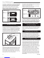
Install the Optional Ash Door Heat Shield
1. Remove the two (2) Phillips pan head screws from
the ash door.
2. Insert the screws through the ash door heat shield
(from the painted side), place the 5/16” spacers over
the screws, and carefully thread them back into the
original holes. The curved lip should be upward,
under the ashlip of the stove.
3. Tighten securely.
Install the Optional Bottom Heat Shield
NOTE: The Bottom Heat Shield is required in most installations. Refer to Floor Protection, Page 9, for further
details. The bottom heat shield comes with the ash pan
heat shield.
1. Remove the four 10-24 x 1/2” hex head bolts from
the corners of the ash drop on the stove bottom.
2. Screw the four (4) 1¹⁄₄" spacers into the holes from
which you removed the bolts, finger-tight.
3. Align the bottom heat shield against the spacers with
the stepped side toward the rear of the stove.
4. Secure the shield with the four (4) hex head bolts
removed from the stove bottom previously.
5. Tighten securely.
Spacers
ST634
Fig. 16 Use spacers and screws to position the ashdoor heat
shield.
ST634
Attach the Primary
Encore Air Thermostat Handle
The primary airashdoor
thermostatshield
handle is the smaller of the
two black handles.
Secure
the
handle to the stub on
2/01
the right side of the stove with an 8-32 x 2” slot head
machine screw.
Attach the Damper Handle
Use the 1/4” -20 x 3” screw to attach the damper handle
to the damper stub on the left side.
Assemble the Removable Insert Handle
ST633
Fig. 15 Use four (4) spacers to attach the bottom heat shield.
12
ST633
Encore
Bottom Heat Shield
Downloaded from www.Manualslib.com manuals
2/01 search engine
The white removable insert handle opens and closes the
front doors. Remove after each use so it won’t get hot.
Store it in the handle holder installed behind the right
front leg. Assemble the handle by passing the 86 mm
(3³⁄₈") screw through the ceramic shaft and into the bright
metal nub. Tighten carefully until snug.
30003842
Encore Woodburning Stove
ST635
Fig. 17 Attach thermostat handle.
ST540
Fig. 18 Assemble the front door handle.
Operation
ST635
Encore
The Encore
InstallControls
thermostat
handle
Two controls regulate the performance of the Encore: a
2/01 oxygen for the fire, and a
primary air control supplies
damper directs air flow within the stove to activate and
deactivate the catalytic combustor.
Symbols cast into the stove are reminders of the correct
directions for opening and closing the controls. The
symbols assume that you are facing the front of the
stove.
Damper Handle
Griddle Handle
Door Handle
Air Control
Lever
Door Handle
Holder (Behind leg)
For the greatest air supply and maximum heat output
(but the shortest ST540
burn time), move the lever toward the
front of the stove.Assembly
For a fire that will last longer with less
handle
heat, move the lever
toward the rear of the stove.
11/00
The Encore’s air control system also features an
automatic thermostat to ensure an even heat output
at whatever manual setting you select. The thermostat
senses the heating and cooling of the stove surface
and adjusts the air shutter accordingly.
Low Heat
High Heat
Ashdoor
Handle
Andirons
ST637
ST636
Fig. 19 The Encore controls are conveniently located and
easy to operate.
ST633
A Single Air
Control Regulates
Encore
Heat Output
and Burn Time
controls
The primary air control
lever, located on the right side
of the stove, controls 2/01
the amount of incoming air for
starting, maintaining, and reviving a fire.
More air entering the stove makes the fire burn hotter
and faster, while less air prolongs the burn at a lower
heat level. High and low settings appear in Figure 20.
30003842
Downloaded from www.Manualslib.com manuals search engine
Fig. 20 The handle may be positioned anywhere between the
two extremes for different heat levels.
A Damper Directs Air Flow
Within the Stove
ST637
encore
The damper is open when
the handle points to the
back of the stove, enabling smoke to pass directly into
Airmustcontrol
the chimney. The damper
be open when starting
or reviving a fire, and whenever the griddle or doors are
opened.
2/01
The damper handle on the left side of the stove opens
and closes the damper to direct air flow within the
stove.
13
Encore Woodburning Stove
The damper is closed when the handle points forward.
Smoke from the fire is directed through the catalytic
combustion system where it can be further burned for
greater efficiency, before passing up the chimney.
When closing the damper, be sure to pull firmly
enough to snap it into the locked position.
To reduce the risk of breaking the glass, avoid striking
the glass or slamming the doors.
When not using the door handle, store it in the holder
behind the right front leg of the stove.
Clockwise to
OPEN
Damper Positions
Open
(Updraft Mode)
Counterclockwise
to CLOSE
ST544
Closed
(Catalytic Mode)
Fig. 23 To open the front doors, turn the handle clockwise.
ST638
Fig. 21 The damper is either open or closed. There are no
intermediate positions.
ST638
Encore
In addition, however, the front doors open for adding an
Encore is not
approved
occasional log to a fire. The
damper
control
in Europe for operation with the front doors open.
2/01
To open the front doors, insert
the handle into the door
Two Ways to Add Fuel
The Encore’s griddle lifts for convenient top-loading of
logs, and is the easiest way to regularly add fuel.
latch stub and turn it to the left and up. (Fig. 23)
Handle
Quadrants
This stove is designed to operate efficiently with
the fire doors (front doors and griddle) closed. The
firebox and ash doors should be kept closed at all
times except when refuelling or removing ashes.
Infrared Reflective Glass Panels
for Clear Fire Viewing
The inner surfaces of the infrared reflective glass
panels are kept at a higher temperature than the outer
surface. This design, along with a preheated ‘airwash,’
makes clear fire viewing possibleST544
at most levels of
operation.
door open
11/00
Andirons Help Protect the Glass
Your stove has andirons to keep logs away from the
glass panels. The andirons are essential to maintain
clear fireviewing, and should be left permanently in
place. Since the andirons may slightly hinder refueling
through the front doors, most stove owners will prefer
the convenience of top loading through the griddle.
Burn Only High-Quality Wood
The Encore is designed to burn natural wood only; do
not burn fuels other than that for which it was designed.
ST639
Fig. 22 the Encore’s hinged griddle makes it easy to top-load
wood.
To close them, always close the left door first. Turn the
handle in the right door to the left and up (to the open
position) and close it. Finally, push on the door as you
turn the handle to the right and down. The doors will
draw in slightly, and the handle should offer some resistance as you turn it to the closed position.
14
ST639
Encore
griddle open
3/1/01 djt
Downloaded from www.Manualslib.com manuals search engine
You’ll enjoy the best results when burning wood that
has been adequately air-dried. Avoid burning “green”
wood that has not been properly seasoned, or cordwood dried more than two years. Do not burn construction materials; they often contain chemicals and
metals that can damage the catalytic combustor. The
wood should be 400-500 mm (18-20”) in length.
The best hardwood fuels include oak, maple, beech,
ash, and hickory that has been split, stacked, and airdried outside under cover for at least one year.
If hardwood is not available, you can burn softwoods
which include tamarack, yellow pine, white pine, Eastern red cedar, fir, and redwood. These too should be
properly dried.
30003842
Encore Woodburning Stove
Store wood under cover to keep it dry. The longer it is
stored, the better heating and fireviewing performance
you will enjoy. Even for short-term storage, however,
keep wood a safe distance from the heater and keep
it out of the areas around the heater used for refueling
and ash removal.
A Surface Thermometer is a
Valuable Guide to Operation
An optional surface thermometer lets you know when
to adjust the air control, when to refuel, and when your
catalyst is operating properly. (Fig. 24)
The control setting also depends on your particular
installation’s “draft,” or the force that moves air from the
stove up through the chimney. Draft is affected by such
things as the length, type, and location of the chimney,
local geography, nearby obstructions, and other factors.
Refer to Page 23 for details on how the installation affects performance.
Too much draft may cause excessive temperatures in
the Encore, and could even damage the combustor.
On the other hand, too little draft can cause backpuffing
into the room and/or the “plugging” of the chimney or
combustor.
How do you know if your draft is excessively high or
low? Symptoms of too much draft include an uncontrollable burn or a glowing-red stove part. A sign of inadequate draft is smoke leaking into the room through the
stove or chimney connector joints, low heat, and dirty
glass.
ST523
Fig. 24 Take temperature readings with the thermometer
located in the middle of the griddle.
For example, when the thermometer registers at least
230° C (450° F) after start-up you know the stove is
hot enough to begin catalytic combustion and it may
be time to close the damper. Note that the stove will
warm up much sooner than the chimney, though; a
warm chimney is the key to easy, effective stove operation. Please review the draft management information
on Page 23 to see how the size, type, and location of
your chimney will affect your stove operation. When
thermometer readings drop below 175° C (350° F) it’s
time to adjust the air control for a higher burn rate or to
reload the stove. A temperature reading over 385° C
(750° F) is a sign to cut back on the air supply to slow
the burn rate.
ST523
Intrepid
Use the following temperature ranges as a guide to
temp readings
operation:
• Readings in the 175-260°
C (350-500° F) range
11/00
indicate low to medium heat output.
• 260-315° C (500-600° F) readings indicate medium heat output.
• Readings of 315-400° C (600-750° F) indicate
high heat output. Operating your Encore continuously at
griddle temperatures of 385° C (750° F) or higher may
damage the cast iron or enamel finish.
Use the Air Control Settings
that Work Best for You
No single air control setting will fit every situation. Each
installation will differ depending on the quality of the
fuel, the amount of heat desired, and how long you wish
the fire to burn; outdoor air temperature and pressure
also affect draft.
30003842
Downloaded from www.Manualslib.com manuals search engine
In some newer homes that are well-insulated and
weather-tight, poor draft may result from insufficient air
in the house. In such instances, an open window near
the stove on the windward side of the house will provide
the fresh air needed.
In some areas provisions for outside combustion air
are required. Refer to section 2 of Document J which
requires an outside air vent for appliances with power
outputs over 5 kW. Always refer to national and local
codes to determine your specific requirements.
Your Encore will accept a duct to deliver outside air for
combustion.
When first using the stove, keep track of the air control
settings. You will quickly find that a specific setting will
give you a fixed amount of heat. It may take a week or
two to determine the amount of heat and the length of
burn you should expect from various settings.
Most installations do not require a large amount of
combustion air, especially if adequate draft is available.
Do not for any reason attempt to increase the firing
of your heater by altering the air control adjustment
range outlined in these directions.
Use the following air control settings as a starting point
to help determine the best settings for your installation.
Each is described as a fraction of the total distance the
lever may be moved from right to left.
Encore Control Settings
Burn Rate
Primary Air Control
Low
From far right to 1/3
the distance to left
Medium
From 1/3 to 2/3 the distance
to left
High
From 2/3 the distance
to left to far left
15
Encore Woodburning Stove
High-Efficiency Wood Burning with
Catalytic Combustion
An Encore leaves the factory with the combustor installed.
In the United States, it is against the law to operate this
wood heater in a manner inconsistent with operating
instructions in this manual, or if the catalytic combustor
is deactivated or removed. The components of the catalytic combustion system in your Encore work together to
produce optimum conditions for secondary combustion.
When the damper is closed, smoke travels through
the catalytic element, which causes ignition of smoke
at temperatures of 260-315° C (500-600° F), half the
temperature normally required for unaided secondary
combustion.
The catalytic element is a ceramic “honeycomb” coated
with the catalytic material. The element is located in the
secondary combustion chamber, molded from a special
high-temperature insulating refractory material. The
chamber provides the correct environment necessary
for secondary combustion of the fuel (smoke).
Closing the damper exposes the smoke to the combustor. If the combustor is at least 316° C (600° F), it will
begin to burn the smoke.
Closing the stove damper may also reduce the draft,
so to avoid putting out the fire or deactivating the
combustor, close the damper only when a fire is wellestablished. When starting a fire, wait until the fire is
well established and there is an ember bed of at least
76-102 mm (3-4”) before closing the damper.
Never kindle a fire with colored paper or paper that
has colored ink or a glossy surface, and never burn
treated wood, garbage, solvents, or trash. All of these
may poison the catalyst and prevent it from operating
properly. Never burn cardboard or loose paper except
for kindling purposes. Never burn coal; doing so can
produce soot or large flakes of char or fly ash that can
coat the combustor and cause smoke to spill into the
room. Coal smoke also can poison the catalyst so that it
won’t operate properly.
To determine whether the combustor is operating, observe the amount of smoke leaving the chimney when
the damper is activated and when it is not. This procedure is described on Page 27.
Avoid using a full charge of very dry wood in the firebox. This may result in continuous very high temperatures in the secondary combustion area and damage
the combustor. Wood which has been split, and stored
under cover for more than 18 months may be considered very dry. Also, do not use a full load of dry slab
wood or scrap wood. For long burns, use a mix of dry
and moderately dry wood.
Conditioning Your Stove
Cast iron is extremely strong, but it can be broken with
a sharp blow from a hammer or from the thermal shock
of rapid and extreme temperature change.
The cast plates expand and contract with changes in
temperature. When you first begin using your Encore,
minimize thermal stress by allowing the plates to adjust
gradually during three or four initial break-in fires following Steps 1-3 below.
Starting and Maintaining a Wood Fire
Burn only solid wood in the Encore, and burn it directly
on the grate. Do not elevate the fuel. Do not burn coal
or other fuels.
The damper must be open when starting a fire or
when refueling.
Do not use chemicals or fluids to start the fire. Do
not burn garbage or flammable fluids such as gasoline, naptha, or engine oil.
1. Open the stove damper, and open the primary air
control fully.
2. Place several sheets of crumpled newspaper in the
stove. DO NOT use glossy advertisements or colored paper, as they can poison the catalyst. Place
on the paper six or eight pieces of dry kindling split
to a finger-width size, and on the kindling lay two or
three larger sticks of split dry wood approximately
25-51 mm (1-2”) in diameter.
In general, the fire must be sufficiently well-established
to ensure that catalytic activity is initiated. When first
starting a fire, a medium- to high- firing rate must be
maintained until the stove, catalyst, and fuel are all
stabilized at the proper operating temperatures.
Even though it is possible for the fire to get quite hot
within a few minutes after a fire is started, the combustor may stop working or the fire may go out if the fire
is allowed to die down immediately as a result of the
damper being closed. Once the combustor starts working, heat generated by burning the smoke will keep it
working.
ST263
Fig. 25 Start fire with newspaper and dry kindling.
30003842
16
Downloaded from www.Manualslib.com manuals search engine
ST263
starting a fire
Encore Woodburning Stove
Never use gasoline-type lantern fuel, kerosene, charcoal lighter fluid, or similar liquids to start or “freshen
up” a fire. Keep all such liquids well away from the
Encore while it is in use.
3. Light the newspaper and close the door. Gradually
build up the fire by adding a few 76-127mm (3-5”) diameter splits. If this is one of the first few “break-in”
fires, let the fire burn brightly, and then let it die out.
During the break-in fires, do not let the stove get hotter than 260° C (500° F) as measured on an optional
stove-top thermometer. Adjust the air control lever as
necessary to control the fire.
Some odor from the stove’s hot metal, the paint, and
the cement is normal for the first few fires.
NOTE: Some chimneys need to be “primed,” or
warmed up, before they will draw sufficiently to start
a fire. To correct this situation, roll up a couple pieces
of newspaper, place them on top of the kindling and
toward the back of the stove, light them, and close
the doors. This will encourage smoke to rise rapidly,
encouraging a good draft.
Once the draft is established, open the front door and
light the rest of the fuel from the bottom. Do not light
the main bed of fuel until the chimney begins drawing,
and repeat the procedure as often as necessary if the
initial attempt is unsuccessful.
4. If your Encore has been broken-in previously using
Steps 1-3, continue to build the fire gradually. Add
larger wood with a diameter of 76-102 mm (3-4”).
Continue adding split logs of this size to the brisklyburning fire until there is a glowing ember bed at
least 76 mm (3”) deep. A good ember bed is necessary for proper functioning of the catalytic system
and may take an hour or more to establish.
NOTE: Stove installations vary, and the operating
guidance given here is only a starting point. The draft
management information on Page 25 will explain in
detail how the features of your installation may help or
hinder good draft.
Refuel While the Embers Are Still Hot
When reloading, best results will be achieved if you first
de-ash the stove by stirring the fuel bed to allow ash to
fall through the grate into the ash pan.
Do not break the charcoal into very small pieces or
pound or compress the charcoal bed.
It is important that air can circulate through the charcoal
bed during the burn. Larger pieces of charcoal allow
more air to circulate under the wood, resulting in the
fire reviving more quickly.
ST264a
Fig. 27 Add full-size logs when the kindling has burned down
to a bed of embers.
For best results when refueling, wear stove gloves to
protect your hands, add fuel while the stove still has
plenty of glowing embers
to re-kindle the fire, and
ST264a
include some smaller pieces of wood in the new fuel
add wood fire
load to help the stove regain its operating temperature
11/00 as a guide to successful
quickly. Use this sequence
refueling.
NOTE: Door handles can be hot. A glove has been included with your stove.We recommend using this glove
whenver operating door or damper controls and especially when operating the top griddle.
ST265
Fig. 26 Add larger pieces of wood as the fire begins to burn
well.
5. Close the damper when the griddle temperature
reaches 230° CST264
(450° F).
6. Adjust the air control
good for
fireyour desired heat output.
12/99
30003842
Downloaded from www.Manualslib.com manuals search engine
1. Open the damper.
2. De-ash the stove as described above. Open the
front doors and check the level of ash in the ash
pan. Empty the pan if necessary and replace it in the
stove. Close the front doors.
3. Open the griddle, load the wood (smaller pieces
first), and close the griddle.
4. Close the damper.
5. When the surface temperature reaches 230° C
(450°F), adjust the air control for the amount of heat
you desire.
NOTE: If the remaining charcoal bed is relatively thick
and if your fuel is well seasoned, it is possible to add
17
Encore Woodburning Stove
fresh fuel (smaller pieces first), close the door and
damper, and reset the primary air thermostat for the
desired heat output.
• Remove the ash pan, making sure to keep it level.
• To keep the cover from sliding off and to keep ash
CAUTION: The Encore will be hot while in operation. Keep children, clothing and furniture away.
Contact may cause skin burns.
DO NOT OVERFIRE THIS HEATER. Overfiring may
cause a house fire, or can result in permanent damage to the stove and to the catalytic combustor. If
any part of the Encore glows, you are overfiring.
You should remove ash before it reaches the top of the
ash pan. Check the level at least once a day. Every few
days, clear any ash from the outer edges of the firebox.
Most of the ash will fall through the grate. Slice or stir
the ash with a shovel or poker so that it falls through the
grate slots.
IMPORTANT: Check the level of ash in the ash pan
before reloading the stove. If the ash level is close to
the top edge of the pan, empty the pan according to this
procedure:
• Open the damper.
• Open the griddle or front doors, and use a shovel or
•
•
•
Ash Disposal
•
•
poker to stir excess ash through the ash slots in the
grate down into the ash pan.
Close the griddle or doors, and unlatch the ash door.
It will pivot, swinging the ash pan out of the stove.
Slide the cover onto the pan, making sure it is securely closed. (Fig. 28)
from falling on the floor, do not tilt the ash pan forward.
If the stove is in operation, close the ash door while
disposing of the ash.
Properly dispose of the ash in a metal container with
a tight-fitting lid. Store the container outdoors away
from all combustible material.
Return the ash pan to its original position in the
stove, and close and latch the ash door.
Do not operate the stove with the ash door open.
This will result in over-firing, and could cause damage to the stove, void the warranty, or even lead to a
house fire.
Empty the ash pan regularly, typically every one to
three days. The frequency will vary depending on how
you operate your Encore: ash will accumulate faster at
higher heat outputs.
Remove ash frequently and place it outdoors in a
metal container with a tight-fitting lid. Place the closed
container of ash on a noncombustible floor or on the
ground, well away from all combustible materials, pending final disposal. If the ash is disposed of by burial in
soil or otherwise locally dispersed, it should be kept in
the closed container until all cinders have thoroughly
cooled.
You can use wood ash as a garden fertilizer.
CAUTION: Never use your household or shop vacuum
cleaner to remove ash from the stove; always remove
and dispose of the ash properly.
Open
Close
ST545
Fig. 29 Turn the handle to the ash pan compartment clockwise to open and counterclockwise to close.
ST566
Fig. 28 Be sure the cover is securely attached before removing the ash pan.
18
ST566
Remove
Ashpan
12/00
Downloaded from www.Manualslib.com manuals search engine
ST545
ashdoor
11/00
30003842
Encore Woodburning Stove
Draft Management
Flue Sizing
A stove is part of a system, which includes the chimney,
the operator, the fuel, and the home. The other parts of
the system will affect how well the stove works. When
there is a good match between all the parts, the system
works well.
Wood stove or insert operation depends on natural
(unforced) draft. Natural draft occurs when the smoke
is hotter (and therefore lighter) than the outdoor air at
the top of the chimney. The bigger the temperature
difference, the stronger the draft. As the smoke rises
from the chimney it provides suction or ‘draw’ that pulls
air into the stove for combustion. A slow, lazy fire with
the stove’s air inlets fully open indicates a weak draft.
A brisk fire, supported only by air entering the stove
through the normal inlets, indicates a good draft. The
stove’s air inlets are passive; they regulate how much
air can enter the stove, but they don’t move air into it.
Depending on the features of your installation - steel or
masonry chimney, inside or outside the house, matched
to the stove’s outlet or oversized - your system may
warm up quickly, or it may take a while to warm up and
operate well. With an ‘airtight’ stove or insert, one which
restricts the amount of air getting into the firebox, the
chimney must keep the smoke warm all the way to the
outdoors. Some chimneys do this better than others.
Here’s a list of features and their effects.
The inside size of a chimney for an ‘airtight’ stove
should match the size of the stove’s flue outlet. When
a chimney serves an airtight, more is not better; in fact,
it can be a disadvantage. Hot gases lose heat through
expansion; if we vent a stove with a 152 mm 96”) flue
collar {181 sq cm (28 sq. in.) area} into a 254 x 254 mm
(10” x 10”) flue, the gases expand to over three times
their original size. This cools the gases, which weakens draft strength. If an oversized flue is also outside
the house, the heat it absorbs gets transferred to the
outdoor air and the flue usually stays cool.
It’s common for a masonry flue, especially one serving
a fireplace, to be oversized for the stove. It can take
quite a while to warm up such a flue, and the results
can be disappointing. The best solution to an oversized
flue is an insulated steel chimney liner, the same diameter as the stove or insert’s flue outlet; the liner keeps
the smoke warm, and the result is a stronger draft. An
uninsulated liner is a second choice - the liner keeps
the smoke restricted to its original size, but the smoke
still must warm up the air around the liner. This makes
the warm-up process take longer.
Masonry Chimney
Masonry is a traditional material for chimneys, but it
can perform poorly when it serves an ‘airtight’ stove.
Masonry is a very effective ‘heat sink’ - it absorbs a lot
of heat. It can cool the smoke enough to diminish draft.
The bigger the chimney, the longer it takes to warm up.
It’s often very difficult to warm up an outdoor masonry
chimney, especially an oversized one, and keep it warm
enough to maintain an adequate draft.
Steel Chimney
Most factory-made steel chimneys have a layer of
insulation around the inner flue. This insulation keeps
the smoke warm. The insulation is less dense than masonry, so a steel chimney warms up more quickly than
a masonry chimney. Steel doesn’t have the good looks
of masonry, but it performs much better.
Indoor / Outdoor location
Because the chimney must keep the smoke warm, it’s
best to locate it inside the house. This uses the house
as insulation for the flue and allows some heat release
into the home. An indoor chimney won’t lose its heat
to the outdoors, so it takes less heat from the stove to
heat it up and keep it warm.
30003842
Downloaded from www.Manualslib.com manuals search engine
Pipe & Chimney Layout
Every turn the smoke must take as it travels to the
chimney top will slow it down. The ideal pipe and chimney layout is straight up from the stove, to a completely
straight chimney. If you’re starting from scratch, use this
layout if possible. If the stovepipe must elbow to enter a
chimney, locate the thimble about midway between the
stove top and the ceiling. This achieves several goals:
it lets the smoke speed up before it must turn, it leaves
some pipe in the room for heat transfer, and it gives you
long-term flexibility for installing a different stove without
relocating the thimble.
There should be no more than 2.4 m (8’) of single-wall
stove pipe between the stove and a chimney; longer
runs can cool the smoke enough to cause draft and
creosote problems. Use double-wall stove pipe for long
runs.
Single venting
Each ‘airtight’ stove requires its own flue. If an airtight
stove is vented to a flue that also serves an open fireplace, or a leakier stove, it’s easier for the chimney draft
to pull air in through those channels than it is to pull air
through the airtight, and performance suffers. Imagine
a vacuum cleaner with a hole in the hose to see the effect here. In some cases the other appliance can even
cause a negative draft through the airtight, and result in
a dangerous draft reversal.
19
Encore Woodburning Stove
Creosote
Creosote is a by-product of slow wood-burning. It’s an
organic tar that can condense in the flue if it’s dense in
the smoke, and slow-moving, and cools off to less than
143° C (290° F). Condensed creosote is volatile, and
can generate chimney fires if it gets hot enough. All the
features that affect chimney draft also affect creosote
condensation - so use whatever combination of installation features and operational steps will encourage good
draft and minimize creosote production.
Because letting the smoke cool off and slow down is
one of the keys to creosote production, it makes sense
to line a chimney to match the stove’s outlet size, for
safety reasons as well as performance. Consult a qualified installer and check local and national codes for
recommended chimney size.
Fuel
Even the best stove installation will not perform well
with poor fuel. The best fuel is hardwood that has airdried 12-18 months. Softwood burns, but not as long as
hardwood. Fairly ‘green’ wood has a good amount of
moisture in it; it will burn, but some of the heat potential
is used to drive the remaining moisture off the wood.
This reduces the amount that reaches your home and
can contribute to a creosote problem. There are moisture meters available for firewood; you can also judge
your wood by its appearance and weight. If you get it
green, lift a piece and get a sense of its weight; it can
lose a third or more of its weight as it dries. Also look at
the ends of a log; as it dries it shrinks and often cracks.
The more weathered and cracked a piece is, the drier
it is.
Dry wood burns readily with a good chimney draft. But
with modern stoves, especially catalytic ones, the wood
can be too dry. While extra-dry wood has little creosote
in it, the remainder can ‘gas out’ from the wood quickly
and densely enough to overload the catalytic burner.
If you hear a rumbling or roaring noise, like a propane
torch, from the stove, that is a sign the catalyst is seriously overfiring. The catalyst is a platinum film on a
ceramic base; the metal can get to higher temperatures
than the ceramic can take, and overfiring the catalyst
can break it. Dry wood can also burn out faster than
you want. If your dry wood burns out too quickly or
overloads the catalyst you can mix in greener wood to
slow the fire down.
Back-puffing
Back-puffing results when the fire produces volatile
gases faster than the chimney draft pulls them out of
the firebox. The gases back up in the firebox till they’re
dense enough and hot enough to ignite. If your stove
back-puffs, you should open the damper to let the
20
Downloaded from www.Manualslib.com manuals search engine
smoke rise to the flue more quickly, let more air into the
firebox, and avoid big loads of firewood. You should
always see lively, dancing flames in the firebox; a lazy,
smoky fire is inefficient, can lead to back-puffing, and
can contribute to creosote buildup in the chimney.
Draft Testing
An easy way to test your chimney draft is to close the
stove’s damper, wait a few minutes to let the airflow
stabilize, then see whether you can vary the strength
of the fire by swinging the air control open and closed.
Results are not always instant; you may need to wait
a few minutes for a change in the air control setting to
have an effect on the fire. If there’s no change, then the
draft isn’t strong enough yet to let you close the damper,
and you’ll need to open it for a while longer and manage
the fire with the air inlet until the draft strengthens. If you
keep track of your burning habits and relate them to their
effects on the stove’s operation, you’ll be rewarded with
good performance and a safe system.
In many cases, local or national codes require the
installation of permanently open air vents, particularly
with larger appliances (i.e. above 5 kW). Refer to these
codes to determine specific requirements for your
installation.
Negative Pressure
Good draft also depends on a supply of air to the stove;
a chimney can’t pull in more air than is available to it.
Sluggish draft results when a house is tight enough to
prevent the ready flow of air to the stove, or by competition between the stove and other equipment that sends
indoor air outside - especially power-driven equipment
like range hoods, clothes dryers, etc. If the chimney
draws well with all other equipment turned off (or
sealed, in the case of fireplaces and/or other stoves),
then you simply need to be careful with timing the use
of the other gear. If you need to crack a nearby window
or door to enable the chimney to pull well, that’s a sign
that you should install an outside-air intake to bring
combustion air directly to the stove. For most of our
stoves we carry adapters to attach to the stove to connect an air duct for outdoor combustion air.
Conclusion
Wood-burning is an art rather than a science. Once the
stove and chimney system are in place, you can only
vary your technique, mostly your timing, to achieve
good results. If you keep track of your burning habits
and relate them to their effects on the stove’s operation,
you’ll be rewarded with good performance and a safe
system.
30003842
Encore Woodburning Stove
Maintenance
Below you will find important information on general
care, inspection and maintenance of your Vermont
Castings stove. Should it become necessary, use only
replacement parts recommended by your authorized
dealer.
Keep Your Stove Looking New
and Working Its Best
Let the fire in the stove go out and allow the stove to
cool completely before beginning any maintenance
procedure.
Care of the Cast Iron Surface
An occasional dusting with a dry rag will keep the painted
cast iron of your Encore looking new.
The stove’s paint can be touched up as needed. First,
mask the areas, such as enamelled parts, glass, or
handles, around the spot to be painted. Clean the spot
with a wire brush. Remove the griddle and set it aside.
Then, touch up the stove with Vermont Castings’ high
temperature stove paint. Apply the paint sparingly; two
light coats of paint are better than a single heavy one.
Removing the Glass
The left door is slightly different from the right in that
one of its retainer clips is located under the door manifold.
1. Remove the right and left door assemblies by raising
the door until the lower hinge pin clears its drilling;
then, angle the door bottom slightly outward and
pull down to release the upper hinge pin. Place the
doors face down on a padded work surface.
2. Remove the screws that hold the retainer clips in
place, and remove the clips. On the right door, remove the Phillips head machine screw that secures
the door manifold to the upper right of the door (as it
faces you). Swing the door manifold out of your way
and remove the clip beneath it as well.
3. Carefully lift the broken glass panel from the door.
Glass Panel
Gasket
Manifold
Care of the Porcelain Enamel Surface
Use a dry or slightly damp rag or soft brush to remove
spills or stains. For difficult jobs that require a cleaning
agent, use only a kitchen appliance cleaner or polish
recommended for use on enamel surfaces.
Cleaning the Glass
Most of the carbon deposits on the glass will burn off
during hot fires.
However, the ash residue that accumulates on the
glass surface should be removed regularly to prevent
etching. To clean the glass, follow this procedure:
• Be sure the glass is completely cool.
• Clean the glass with water or a cleaner made espe•
•
cially for this purpose. Do not use abrasive cleaners.
Rinse the glass thoroughly.
Dry the glass completely.
Replace Broken Glass Immediately
Do not operate your stove if the glass in the doors is
damaged.
If you need to replace the glass, use only the high temperature ceramic glass supplied by Vermont Castings.
Do not use substitutes. Be sure to specify left or right
glass; the panels are not interchangeable.
30003842
Downloaded from www.Manualslib.com manuals search engine
Retainer Clips (4)
ST640
Fig. 30 An exploded view of the glass assembly for the left
door.
InstallingST640
the Glass
Encore
Check the gasket around the window; it should be soft
door
glass against the
and resilient so the glass will
seal properly
door. Replace the gasket if it3/01
has hardened or if it is
compressed.
1. Center the first pane of glass on the gasket. Be sure
to place the glass so the infrared reflective coating is
on the exterior side.
2. Secure the glass on both doors with the retainer
clips except the one that belongs under the manifold
of the right door, but leave the screws a little loose.
Position the remaining clip under the right door
manifold, and swing the manifold back into position
on the door. Make sure the screw passing through
the end of the manifold nearest the center of the
door also passes through the retainer clip.
21
Encore Woodburning Stove
3. Replace the doors on the stove. Remove the griddle
so you can reach in through the opening to position the manifold. Move the door manifold as high
as possible without actually touching the upper air
manifold, and as far toward the center of the stove
as possible without hitting the door manifold on the
other door. Tighten all screws.
4. Open and close the doors to check that the door
manifold does not interfere with either of the other
manifolds. Adjust as necessary.
2. Turn the pressure screw approximately one half turn
clockwise.
3. Tighten the lock nut. Keep the pressure screw from
turning as you tighten the nut. Re-test the damper.
Lock Nut
Damper
Pressure Adjusting Screw
Check the Operation
of the Primary Air Shutter
The primary air shutter is located at the back of the ash
drop and is visible from the back of the stove. (Fig. 31)
The shutter must open and close freely when you move
the thermostat lever. If it does not, remove any obstruction. If you need assistance, consult your local Vermont
Castings Authorized Dealer.
ST642
Fig. 32 Adjusting the damper.
Tighten the Damper Handle as Needed
A handle on the left side of the stove controls the
damper. The handle
attaches to the damper rod with a
ST642
set screw. Periodically check the set screw and tighten
Encore
as necessary.
damper adjust
3/01
How to Adjust the Door Latches
The Encore’s front doors, as well as its ash pan door,
should close securely to prevent accidental opening and to keep air from leaking into the stove. On
adequately adjusted doors, the handles should resist
slightly as they are turned to the closed position and the
doors themselves should be drawn slightly toward the
stove.
Primary Air
Shutter
ST641
Fig. 31 The primary air shutter must move freely.
Do not change the adjustment of the cable in an attempt to gain increased firing. The air shutter controls
ST641
how much air can enter the stove, but chimney draft
Encore
is the force that pulls
air into the stove. If changing the
thermostat handle
does not lead to changes in
airposition
shutter
the fire’s intensity,
it
is
probably
due to weak chimney
3/01
draft (in the case of a weak fire you can’t increase) or
an air leak in the stove (in the case of a fire you can’t
decrease).
Over time, the gasket around the doors will compress
and the latch may need adjustment.
To adjust the handle on the front doors, open the
door on which the handle is mounted and rotate the
handle one full turn counterclockwise. Since this handle
is threaded into the front door, a complete revolution will
adjust it enough so the doors close securely.
To adjust the latch on the ash pan door, loosen the
small lock nut, rotate the striker screw a half-turn, and
re-tighten the small lock. Hold the striker screw to keep
it from turning as you tighten the lock nut. Make repeated small adjustments until the setting is right.
Adjust the Damper as Needed
The tension on the Encore’s damper is adjustable to
compensate for compression of the gasket that seals
the damper to the upper fireback. To adjust the damper:
1. Remove the griddle. Loosen the lock nut at the center of the damper.
22
Downloaded from www.Manualslib.com manuals search engine
30003842
Encore Woodburning Stove
• Then, open the stove damper and once again
check the smoke leaving the chimney. Significantly
more smoke should be seen when the stove damper is
open and exhaust does not pass through the combustor. Be careful not to confuse smoke with steam from
wet wood, however. Steam dissipates in the air quickly;
smoke does not.
If this test indicates a problem, consider other possible
factors as well, such as the time of year or a change in
the quality of your fuel. In spring and fall, draft is weaker
than it is in colder winter weather, and fires can burn
sluggishly. Small, hot fires are a good solution under
these conditions.
Pawl
Small
Locking Nut
Striker Screw
Large Locking Nut
Set Screw
Handle Stub
ST531
Fig. 33 Turn the door latch striker screw in or out to tighten or
loosen the door latch.
ST531
Door
Pawl
The Catalytic
Element
11/00
Inspection and Cleaning
This wood heater contains a catalytic combustor, which
needs periodic inspection and replacement for proper
operation. In the United States it is against the law to
operate this wood heater in a manner inconsistent with
the operating instructions in this manual, or if the catalytic element is deactivated or removed.
Under normal operating conditions, the catalytic combustor should remain active for two to six years (depending on the amount of wood burned). However, it
is important to monitor the combustor periodically to
ensure that it is functioning properly, as well as to determine when it needs to be replaced. A non-functioning
combustor will result in a loss of heating efficiency, and
an increase in creosote and emissions.
Burning “green” (insufficiently seasoned) wood will result in poorer performance than when burning properly
seasoned fuel. You may have to run your stove hotter
(more air) to achieve good performance with green or
wet wood.
Also, consider any changes in your operating routine.
Once you have ruled out any other possible causes for
a decline in performance, you may inspect the combustor.
Inspecting the Combustor
1. Release the hood from the fireback by swinging the
hood upward and then sliding it to either side. (Fig.
34)
2. Using a flashlight, and a mirror if necessary, examine the combustor. If no fly ash or damage is visible,
the inspection is complete and you may replace the
hood. If further examination or cleaning is necessary,
go to Step 3.
Hood
Inspect the combustor “in place” for fly ash accumulation and physical damage three times per year. Do not
remove the combustor unless a more detailed inspection is warranted because of diminished performance
as outlined below.
The refractory package that houses the catalytic combustor should be inspected annually for a buildup of fly
ash and cleaned if necessary. This may be done when
you examine the combustor.
When to Suspect a Combustor Problem
The best way to evaluate the performance of your
Encore’s combustor is to observe the amount of smoke
leaving the chimney — both when the combustor has
achieved “light-off” and when it has not. Follow these
steps:
• With a fire going and the combustor properly activated, with the damper closed to route smoke through
it as described in the Operation Section, go outside and
observe the smoke leaving the chimney.
30003842
Downloaded from www.Manualslib.com manuals search engine
Fireback
ST643
Fig. 34 Release the hood by lifting its bottom edge and sliding to one side.
3. Release the fireback by prying the left and right
wedges upward. ST643
(Fig. 35)
4. Swing the fireback
forward and up to remove it from
Encore
the stove. (Fig. 36)
catalyst hood
5. Remove the catalytic combustor’s refractory access
remove
cover, then remove
the combustor.
3/01
23
Encore Woodburning Stove
Left Wedge
Refractory Access Cover
Right Wedge
1"
ST559
ST644
Fig. 35 Release the lower fireback by tapping out two
wedges.
ST644
ST559
10. Clean the chimney
and chimney connector.
Secondary
Operate the stove in Probe
your typical
manner for two weeks,
inspection
inspecting the chimney
and the chimney connector
11/00
frequently during this period.
Encore
release
Fireback
lower fireback
3/01
If creosote is not building up as fast, it is likely the
performance change was caused by fly ash deposits
on the catalytic element. However, continue the inspections of the chimney system for a few weeks to ensure
proper performance continues.
ST645
Fig. 36 Remove the lower fireback through the front door
opening.
6. Check the combustor’s honeycomb-like element
ST645
for a buildup of
fly ash. If any is evident, take the
Encore
combustor outside
and clean it by blowing air gently
through it. remove fireback
7. Inspect the element
3/01 for damage or degradation.
Although small hairline cracks will not affect performance, the element should be essentially intact.
If the element is broken in pieces or has sections
missing, it should be replaced. Call your local Vermont Castings’ Authorized Dealer for a replacement
element.
While the catalytic element is removed, check the
condition of the secondary air probe. Use an inspection mirror to locate the probe within the combustion
chamber. The probe should extend 25-38 mm (1” to
1¹⁄₂”) into the chamber and show no signs of deterioration, such as warping, corrosion, or short length. (Fig.
37) A damaged secondary air probe can affect catalytic
performance. If the probe needs replacement, contact
your local dealer.
8. If the element is in good condition and clean, re-install it in the stove and replace the refractory access
cover.
9. Replace the fireback, install the two wedges, and
replace the cast iron hood.
24
Downloaded from www.Manualslib.com manuals search engine
Fig. 37 Use an inspection mirror to check the reflected view
of the secondary probe.
If you continue to find a significant creosote buildup or if
you continue to see excessive smoke from the chimney,
the catalytic element will need to be replaced. Contact
your nearest Vermont Castings’ Authorized Dealer for
information about a replacement element.
NOTE: Use only the replacement catalyst supplied by a
Vermont Castings dealer.
Replace the Stove Gaskets as Needed
Your Encore uses rope-type fiberglass gaskets to make
a tight seal between some parts. With use, particularly
on those parts that move, gaskets can become brittle
and compressed and can begin to lose their effectiveness. These will need periodic replacement.
All of the gaskets are made of fiberglass. The sizes of
replaceable gasket are listed below, along with their
applications.
Gasket Diameter
5/16”
3/8”
3/16”
5/16”
...And the Parts it Seals
The griddle to the stove top
(wire reinforced gasket)
The ash door to the front of
the ash drop
The outer glass panes to the
doors
The damper to the
upper fireback; the front doors
to the stove front; and the
doors to each other.
30003842
Encore Woodburning Stove
If you need to change a gasket, first obtain an appropriate replacement from your Vermont Castings’ Authorized Dealer.
Wait until the fire is out and the stove has cooled. Be
sure to follow the standard safety procedure for working
with dusty materials: Wear safety goggles and a dust
mask.
The procedure for replacing gaskets is the same regardless of the gasket location. Follow these steps:
meets before trimming any excess. Do not overlap the
gasket ends or leave ends with ragged edges.
7. Press the gasketed part firmly against its normal
mating surface to seat the gasket evenly in its channel.
Close and latch the door to do this, or tap other parts
with the rubber mallet (or hammer/block of wood).
8. Clean any excess cement from around the channel, then let the cement that holds the new gasket dry
thoroughly.
1. Remove the existing gasket by grasping an end and
pulling firmly.
Adjust the Door If Necessary
2. Use a wire brush or the tip of a screwdriver to clean
the channel of any remaining cement or bits of gasket.
(Fig. 38) Remove stubborn deposits of cement with a
cold chisel if necessary.
The stove’s door(s) may need adjustment after you
have regasketed it. Initially, it may require loosening to
accommodate the new gasket; after a few weeks, it
may need tightening to compensate for compression of
the new gasket. The directions for adjusting the doors
are on Page 22.
Permanent Encore Gaskets
ST560
Fig. 38 Remove gasket then
clean channel with wire brush.
ST559
3. Determine the correctRemove
length of the appropriategasket
sized gasket by laying it out
in the
11/30/00
djt channel. Allow an
extra 25-51 mm (1-2”), and mark the spot to be cut.
(Fig. 39)
4. Remove the gasket from the channel, place it on a
wood cutting surface, and cut it at the marked spot with
a utility knife. Twist the ends slightly to keep the gasket
from unraveling.
et
ask
ve G ent
Sto Cem
ST561
Fig. 39 Lay a bead of gasket cement then press gasket in
place.
5. Lay an unbroken 3 ST559
mm (1/8”) bead of gasket cement
Remove
in the newly-cleaned channel.
gasket
Other gaskets form seals between non-moving parts,
but these are not subject to the same wear and deterioration as gaskets on moving parts. It is unlikely that
you will ever need to replace these gaskets unless the
involved parts are disassembled and then put back
together. If this is the case, the job should be done only
by a qualified service technician.
5/16” diameter gasket seals the following parts:
•The flue collar to the stove back
•The lower fireback to the sides
The Chimney System
Creosote
Your Encore is designed to reduce creosote build-up
significantly. However, regular chimney inspection and
maintenance must still be performed. For safety, good
stove performance, and to protect your chimney and
chimney connector, inspect your chimney and chimney
connector on a regular schedule. Clean the system if
necessary. Failure to keep the chimney and connector
system clean can result in a serious chimney fire.
When wood is burned slowly, it produces tar, organic
vapors and moisture that combine to form creosote.
The creosote vapors condense in the relatively cool
chimney flue of a slow-burning fire. As a result, creosote residue accumulates on the flue lining. When ignited, this creosote makes an extremely hot fire within the
flue system that can damage the chimney and overheat
adjacent combustible material. If a significant layer of
creosote has accumulated —3 mm (1/8”) or more — it
should be removed to reduce the risk of a chimney fire.
6. Starting at one end,11/30/00
press the
djt gasket into the channel. (Fig. 39) Ensure a good joint where the gasket
30003842
Downloaded from www.Manualslib.com manuals search engine
25
Encore Woodburning Stove
If you do experience a chimney fire, act promptly
to:
Annual Maintenance
• Close the damper and thermostat lever.
• Get everyone out of the house.
• Call the Fire Department.
Every Spring, at the end of the heating season, perform
a thorough cleaning, inspection and repair. The stove
and chimney system should be inspected and maintained by a qualified engineer and include the following:
• Thoroughly clean the chimney and chimney connector.
• Inspect the chimney for damage and deterioration.
Replace weak sections of prefabricated chimney.
Have a mason make repairs to a masonry chimney.
• Inspect the chimney connector and replace any
damaged sections.
• Check gasketing for wear or compression, and replace if necessary.
• Inspect and clean the catalytic element, and vacuum
out the ash at the bottom of the back plate after removing the lower fireback. Lightly clean the refractory assembly that houses the element but be careful
not to damage the refractory material, which is very
fragile.
• Check door and damper handles for tightness. Adjust if needed.
• Check heat shield screws. Tighten as necessary.
• Clean dust from the inner sides of bottom, rear and
connector heat shields.
• Remove ashes from the ash pan and replace with
moisture absorbing material (such as cat litter) to
keep the stove interior dry.
• Touch up the paint on black stoves.
You should inspect the system every two weeks during
the heating season as part of a regular maintenance
schedule. To inspect the chimney, let the stove cool
completely. Then, using a strong light, sight up through
the flue collar into the chimney flue. If it is not possible
to inspect the flue system in this fashion, the stove must
be disconnected to provide better viewing access.
Clean the chimney using a brush the same size and
shape as the flue liner. Flexible fiberglass rods are used
to run the brush up and down the liner, causing any
deposits to fall to the bottom of the chimney where they
can be removed through the clean-out door.
Clean the chimney connector by disconnecting the sections, taking them outside, and removing any deposits
with a stiff wire brush. Reinstall the connector sections
after cleaning, being sure to secure the joints between
individual sections with sheet metal screws.
If you cannot inspect or clean the chimney yourself,
contact your local Vermont Castings’ Dealer or a professional chimney sweep.
26
Downloaded from www.Manualslib.com manuals search engine
30003842
Encore Woodburning Stove
Appendix: Catalytic Combustor
In any chemical reaction, including the combustion
process, there are certain conditions which must be
met before the reaction can take place. For example, a
reaction may require a certain temperature, or a certain
concentration of the reactants (the combustion gases
and oxygen), or a certain amount of time. Catalysts,
though not changed themselves during the reaction,
have the ability to act at a molecular level to change
these requirements. In the Encore’s secondary combustion chamber the catalyst reduces the temperature
at which secondary combustion can start from the 540650° C (1000 - 1200° F) range to the 260-315° C (500
- 600° F) range, increasing efficiency, and reducing
creosote and emissions.
The catalytic reaction does have some limitations of its
own. Primary among these is that the reactants (the
gases) come into close physical contact with the catalyst itself.
To ensure the necessary contact, the catalytic element
in your Encore is composed of a ceramic base in the
shape of a honeycomb. Each of the honeycomb’s many
surfaces carries a coating of the catalyst (usually a
noble metal such as platinum or palladium). The large
surface area exposed in this form ensures that the combustion gases have the greatest opportunity to come in
contact with the catalyst.
Loss of catalytic activity will be apparent in several
ways. First you may notice an increase in fuel consumption. Second, there will be a visible increase in the
rate at which creosote builds up in your chimney connector system. You may also notice a heavy discharge
of smoke from the chimney. There are a number of
catalytic problems which can cause loss of activity:
Blockage
While the honeycomb pattern ensures good contact, it
also increases the resistance to flow of the combustion
gases, and, because of the many surfaces, provides
more places for creosote and fly ash to deposit. It is
important to follow the operating instructions in order
to minimize these deposits, and to periodically inspect
your catalyst for signs of blockage.
Masking and Poisoning
While the catalyst itself does not enter into the combustion process, certain elements, such as lead and sulfur,
can attach to the active sites on the surface of the honeycomb. Though the catalyst is still there, it is covered,
or masked, by the contaminant, and cannot function. To
avoid this situation, it is important not to burn anything
in your Encore that is a source of these contaminants.
Particularly avoid painted or treated wood, coal, household trash, colored papers, metal foils, or plastics.
Chemical chimney cleaners may also contain harmful
elements. The safest approach is to burn only untreated, natural wood.
Flame Impingement
The catalytic element is not designed for exposure to
direct flame. If you continually overfire your Encore, the
chemistry of the catalyst coating may be altered, inhibiting the combustion process.
Thermal degradation of the ceramic base may also occur, causing the element to disintegrate. Stay within the
recommended guidelines of the Operation section.
Mechanical Damage
If the element is mishandled, damage may occur.
Always treat the element carefully. Remember the catalyst is made of a ceramic material; treat it as you would
fine china. Hairline cracks will not affect the performance of the catalyst, as long as the steel sleeve holds
the element in the proper position.
Peeling
The surface coat may peel if the catalytic element is
frequently subjected to excessive temperatures. Follow
the operating instructions carefully to avoid this type of
damage.
General
Every Vermont Castings’ Encore is equipped with either
a Corning “Long-Life”® or a Technical Glass Products
“Honeycomb”® combustor. The products are equivalent.
If you must ship your catalytic element for any reason,
remember its fragile nature. Place the element in a
plastic bag, and package it with a generous amount of
shock absorbing material.
30003842
Downloaded from www.Manualslib.com manuals search engine
27
Encore Woodburning Stove
15
16
17
22
18
5
1
14
23
2
6
3
24
8
22
10
9
25
37
21
27
4
7
24
85
38
28
1
36
11
21
89
40
84
41
33
42
31
90
43
35
75
82
44
30
93
74
80
79
51
52
45
43
53
70
58
74
88
71
56a
55
78
56
54
72
93
86
87
50
34
77
39 91
92
60
83
57
73
81
59
80
62
61
CFM Corporation reserves the right to make changes in design, materials, specifications, prices and discontinue colors and products at any time,
without notice.
Encore Woodburning Stove
Model 2550CE
Item Description
1.
2.
3.
4.
5.
6.
Secondary Air Cover Plate
Secondary Air Probe Assy
Secondary Air Link II, ENC
Secondary Air Flap
Flue Collar (8”)
Back
28
Downloaded from www.Manualslib.com manuals search engine
0956
Encore parts
8/02
Part Number
1601492
1601489
1601486
1601490
See Chart Pg. 35
1308620
Item Description
7.
8.
9.
10.
11.
14.
Left Heat Deflector
Right Heat Deflector
Refractory Assy w/Access Panel
Catalytic Combustor
Refractory Access Panel
Left Griddle Quad
Part Number
1608629
1608630
1602510
1602505
1602511
1301807
30003842
Encore Woodburning Stove
Encore Woodburning Stove
Model 2550CE (continued)
Item Description
15.
16.
17.
18.
21.
22.
23.
24.
25.
27.
28.
30.
31.
33.
34.
35.
36.
37.
38.
39.
40.
41.
42.
43.
44.
45.
50.
51.
52.
53.
54.
55.
Part Number
Right Griddle Quad
1301832
Griddle
1300797
Griddle Handle Assy
30002775
Top
See Chart Pg. 36
Wedge
1301810
1
Upper Fireback
1308644
1308631
Damper1
Damper Tabs (3)1
1601488
1600851
Damper Rod1
Combustion Throat Hood
1301145
Lower Fireback
1308646
Damper Handle Screw 1/4-20 x 3³⁄₈” NT 1201294
Damper Handle,Wood
1600664
Steel Handle Stub
30002720
Left Side
See Chart Pg. 36
Left Air Plate (Inner side)
1308621
Right Air Plate (Inner side)
1308622
Right Side
See Chart Pg. 36
Thermostat Handle Assy
5004224
Thermostat Assy
5005470
Grate
1307434
Primary Air Tube Cover Plate
1308609
Primary Air Frame
1307411
Primary Air Valve Only
1301412
Primary Air Rod Only
1601493
Primary Air Regulatory System
5000337
Bottom
1308604
Ashlip
See Chart Pg. 36
Andiron (2)
1307419
Leg
See Chart Pg. 36
Leg Leveler
1201745
Ashdrop
1308603
Pawl Assembly Short Adjustment
30002362
Ashdoor
1308607
Item Description
56.
57.
58.
59.
60.
61.
62.
70.
71.
72.
73.
74.
75.
77.
78.
79.
80.
81.
82.
83.
84.
85.
86.
87.
88.
89.
90.
91.
92.
93.
Part Number
Ashdoor Handle (Wood)
1600663
Ashdoor Hinge Pin
1208608
Cotter Pin, Ashdoor
30001749
Ashdoor Hinge Support
1308605
Ashpan
1601025
Ashpan Bracket
1601039
Ashpan Cover
1601027
Airwash Manifold
1308615
Front II
See Chart Pg. 36
Left Door Air Manifold
1307403
Left Door
See Chart Pg. 36
Door Hinge Strip (2)
1308634
Right Door Air Manifold
1307404
Door Handle Assy w/Set Screw
30002721
Right Door II
See Chart Pg. 36
Door Gasket 5/16 Med. Density 6ND
1203588
Glass Gasket
1203556
Left Door Glass2
1408630
Right Door Glass2
1408629
Door Latch
1408628
Spacer 3/8 x 1-Z
1201779
1301811
Damper Ramp1
Socket Set Screw Adjuster
1200436
PH Flat Hd Screw
1200809
Hex Nuts
1203210
Handle Base Stub3
30002714
Ceramic Handle 2.78 Lg3
20006381
Handle Bolt3
1201294
Friction Spring
1201846
Primary Air Cable w/Clips
5005471
7/16-20 x 1 Socket Set Screw
1200334
Washer
1202471
Pin, Long, Door
30002727
1. Included in #5008649 upper fireback assembly.
2. Not interchangeable, due to a heat-reflective coating on the room
side of the panels.
3. Included in #0004345 ceramic handle assembly.
30003842
Downloaded from www.Manualslib.com manuals search engine
29
Encore Woodburning Stove
Encore Woodburning Stove
Model 2550CE (continued)
Shell Enamel Parts - Encore
Enamel
Color
Top
Classic
1308618
Biscuit
30003007
Bordeaux
2328618
Chestnut Brown 30003019
Ebony
30003031
Forest Green
2318618
Midnight Blue
2378618
Sand
1328618
Suede Brown
30002526
Vermont
Classic Green
30003044
Shell Enamel Parts - Encore
Enamel
Color
Flue Collar
Classic
1304280
Biscuit
30003008
Bordeaux
2324280
Chestnut Brown 30003020
Ebony
30003032
Forest Green
2314280
Midnight Blue
2374280
Sand
1324280
Suede Brown
30002527
Vermont
Classic Green
30003045
Left Side
1308623
30003006
2328623
30003018
30003030
2318623
2378623
1328623
30002524
Right Side
1308619
30003005
2328619
30003017
30003029
2318619
2378619
1328619
30002523
Front
1308635
30003004
2328635
30003016
30003028
2318635
2378635
1328635
30002522
Ashlip
1307406
30003002
2377406
30003014
30003026
2317406
2377406
1327406
30002520
Single Leg
1307427
30003003
2327427
30003015
30003027
2317427
2377427
1327427
30002521
30003043
30003042
30003041
30003039
30003040
Left Door
Subassembly
5008648
30003012
30001144
30003024
30003037
30001150
30001345
30001146
30002531
Left Door
Only
1308637
30003010
2328637
30003022
30003034
2318637
2378637
1328637
30002529
Right Door
Subassembly
5008647
30003011
30001143
30003023
30003036
30001149
30001344
30001145
30002530
Right Door
Only
1308636
30003009
2328636
30003021
30003033
2318636
2378636
1328636
30002528
30003049
30003047
30003048
30003046
30
Downloaded from www.Manualslib.com manuals search engine
30003842
Warranty
Limited 3 Year Warranty
CFM Corporation warrants that this woodburning stove will be free
of defects in material and workmanship for a period of three years
from the date you receive it, except that the catalyst, thermostat
assembly, handles, glass door panels, cement, and gasketing shall
be warranted as described below.
CFM Corporation will repair or replace, at its option, any part found
to be defective upon inspection by a Vermont Castings, Authorized
Dealer. The customer must return the defective part or the stove, with
shipping prepaid, to the Authorized Dealer or pay for any Authorized
Dealer in-home travel fees or service charges for in-home repair work.
It is the dealer’s option whether the repair work will be done in the customer’s home or in the dealer’s shop. If, upon inspection, the damage
is found to be the fault of the manufacturer, repairs will be authorized at
no charge to the customer for parts and/or labor.
Any woodburning stove or part thereof that is repaired or replaced
during the limited warranty period will be warranted under the terms of
the limited warranty for a period not to exceed the remaining term of the
original limited warranty or six (6) months, whichever is longer.
Limited 1 Year Warranty
The following parts of the woodburning stove are warranted to be free
of defects in material and workmanship for a period of one year from
the date you receive it: The thermostat assembly, handles, glass door
panels, cement, and gasketing. Any of these items found to be defective will be repaired or replaced at no charge, upon the return of the
part with postage prepaid to a Vermont Castings Authorized Dealer.
Any part repaired or replaced during the limited warranty period will
be warranted under the terms of the limited warranty for a period not
to exceed the remaining term of the original limited warranty or six (6)
months, whichever is longer.
Limited Catalyst Warranty
The catalyst will be warranted for a six year period as follows: If the
original catalyst or a replacement catalyst proves defective or ceases to
maintain 70% of its particulate emission reduction activity (as measured
by an approved testing procedure) within 24 months from the date the
stove is received, the catalyst itself will be replaced free.
From 25 - 72 months a pro-rated credit will be allowed against a replacement catalyst and the cost of labor necessary for its installation at
the time of replacement.
For stove purchases made after June 30, 1990, a third year
(25 - 36 months) of no charge replacement will be made when combustor failure is due to thermal degradation of the substrate (crumbling of
ceramic material). The customer must pay for any in-home travel fees,
service charges, or transportation costs for returning the stove to the
Authorized Dealer.
Amount of Time
Credit Towards
Since Purchase
Replacement Cost
0 - 24 months
100%
25 - 36 months
50 %
37 - 48 months
30%
49 - 60 months
20%
61 - 72 months
10%
Any replacement catalyst will be warranted under the terms of the
catalyst warranty for the remaining term of the original warranty. The
purchaser must provide the following information in order to receive a
replacement catalyst under the terms of this limited warranty:
1. Name, address and telephone number.
2. Proof of original purchase date.
3. Date of failure of catalyst.
4. Any relevant information or circumstances regarding determination of failure.
5. In addition, the owner must return the failed catalyst.
30003842
Downloaded from www.Manualslib.com manuals search engine
Encore Woodburning Stove
Exclusions & Limitations
1. This warranty is transferable; however, proof of original retail purchase is required.
2. This warranty does not cover misuse of the stove. Misuse includes
overfiring which will result if the stove is used in such a manner as
to cause one or more of the plates to glow red. Overfiring can be
identified later by warped plates and areas where the paint pigment
has burned off. Overfiring in enamel fireplaces is identified by bubbling, cracking, chipping and discoloration of the porcelain enamel
finish. CFM Corporation offers no warranty on chipping of enamel
surfaces. Inspect your woodburning stove prior to accepting it for
any damage to the enamel.
3. This warranty does not cover misuse of the stove as described
in the Owner’s Guide, nor does it cover an stove which has been
modified unless authorized by a CFM Corporation representative in
writing. This warranty does not cover damage to the stove caused
by burning salt saturated wood, chemically treated wood, or any fuel
not recommended in the Owner’s Guide.
4. This warranty does not cover a stove repaired by someone other
than a Vermont Castings Authorized Dealer.
5. Damage to the unit while in transit is not covered by this warranty
but is subject to a claim against the common carrier. Contact
Vermont Castings Authorized Dealer from whom you purchased
your stove or CFM Corporation if the purchase was direct. (Do not
operate the stove as this may negate the ability to process the claim
with the carrier.)
6. Claims are not valid where the installation does not conform to local
building and fire codes or, in their absence, to the recommendations
in our Owner’s Guide.
7. The salt air environment of coastal areas, or a high-humidity environment, can be corrosive to the porcelain enamel finish. These
conditions can cause rusting of the cast iron beneath the porcelain
enamel finish, which will cause the porcelain enamel finish to flake
off. This warranty does not cover damage caused by a salt air or
high-humidity environment.
8. CFM Corporation shall have no obligation to enhance or update any
unit once manufactured.
IN NO EVENT SHALL CFM CORPORATION BE LIABLE FOR INCIDENTAL AND CONSEQUENTIAL DAMAGES. ALL IMPLIED WARRANTIES, INCLUDING THE IMPLIED WARRANTIES OF MERCHANTABILITY AND FITNESS, ARE LIMITED TO THE DURATION OF
THIS WRITTEN WARRANTY. THIS WARRANTY SUPERCEDES ALL
OTHER ORAL OR WRITTEN WARRANTIES.
Some states do not allow the exclusion or limitations of incidential and
consequential damages or limitations on how long an implied warranty
lasts, so the above limitations may not apply to you. This warranty gives
you specific rights and you may have other rights which vary from state
to state.
How to Obtain Service
If a defect is noted within the warranty period, the customer should
contact a Vermont Castings Authorized Dealer or CFM Corporation if
the purchase was direct with the following information:
1. Name, address, and telephone number of the purchaser.
2. Date of purchase.
3. Serial number from the label on the back.
4. Nature of the defect or damage.
5. Any relevant information or circumstances, e.g., installation,
mode of operation when defect was noted.
A warranty claim will then start in process. CFM Corporation reserves
the right to withhold final approval of a warranty claim pending a visual
inspection of the defect by authorized representatives.
31
CFM Corporation
2695 Meadowvale Blvd. • Mississauga, Ontario, Canada L5N 8A3
800-668-5323 • www.cfmcorp.com
Downloaded from www.Manualslib.com manuals search engine