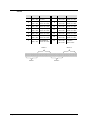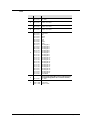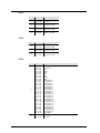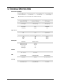
1
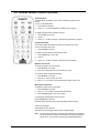
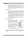
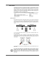
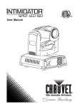
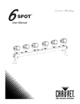
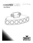
User Manual TABLE OF CONTENTS 1. Before you Begin ............................................................................. 3 What is Included............................................................................................ 3 Unpacking Instructions .................................................................................. 3 Text Conventions .......................................................................................... 3 Icons .............................................................................................................. 3 Safety Notes .................................................................................................. 4 2. Introduction ...................................................................................... 5 Product Overview .......................................................................................... 5 3. Setup ................................................................................................. 6 AC Power ...................................................................................................... 6 Power Linking......................................................................................................... 6 Mounting ....................................................................................................... 7 Orientation ............................................................................................................. 7 Rigging ................................................................................................................... 7 4. Operation .......................................................................................... 8 Control Panel Operation................................................................................ 8 Menu Map ..................................................................................................... 8 Configuration (DMX) ..................................................................................... 9 Starting Address..................................................................................................... 9 Configuration (Standalone Modes) ............................................................. 10 Sound Active Mode .............................................................................................. 10 Automatic Mode ................................................................................................... 10 Wireless Remote Mode ........................................................................................ 10 Master/Slave Mode .............................................................................................. 11 Program Selection................................................................................................ 11 Static Color .......................................................................................................... 11 IRC (Infrared Remote Control) Operation ................................................... 12 DMX Channel Assignments and Values ..................................................... 13 26-CH ................................................................................................................... 13 14-CH ................................................................................................................... 14 7-CH ..................................................................................................................... 15 4-CH ..................................................................................................................... 16 3-CH ..................................................................................................................... 16 2-CH ..................................................................................................................... 16 5. Technical Information.................................................................... 17 General Maintenance .................................................................................. 17 General Troubleshooting ............................................................................ 17 Returns Procedure ...................................................................................... 18 Claims ......................................................................................................... 19 Contact Information ..................................................................................... 19 DMX Primer ................................................................................................. 20 Starting Address................................................................................................... 20 Fixture Linking (Daisy Chain) ............................................................................... 20 DMX Cabling ........................................................................................................ 21 6. Technical Specifications ............................................................... 22 Page 2 of 22 COLORrail™ IRC User Manual (Rev. 03) 1. BEFORE YOU BEGIN What is Included 1 x COLORrail™ IRC 1 x Bracket kit 1 x Power Cord 1 x Warranty Card 1 x User Manual Unpacking Instructions Immediately upon receiving this product, carefully unpack it and check the container in which you received it. Make sure that you have received all the parts indicated above and that they are all in good condition. If the material inside the container (this product and any other accessory included with it) appears damaged from shipping, or if the container shows signs of mishandling, notify the shipper immediately. In addition, retain the container and all the packing material for inspection. See the Claims section in the “Technical Information” chapter. Text Conventions Convention [10] <Menu> Meaning A DIP switch to be configured A key to be pressed on the fixture’s control panel 1~512 A range of values 50/60 A set of values of which only one can be chosen Settings A menu option not to be modified (for example, showing the operating mode/current status) Menu > Settings A sequence of menu options to be followed ON A value to be entered or selected Icon Meaning Icons This paragraph contains critical installation, configuration, or operation information. Failure to comply with this information may render the fixture partially or completely inoperative, cause damage to the fixture, or cause harm to the user. This paragraph contains important installation or configuration information. Failure to comply with this information may prevent the fixture from functioning correctly. This paragraph reminds you of useful, although not critical, information. Document Information The information and specifications contained in this document are subject to change without notice. CHAUVET® assumes no responsibility or liability for any errors or omissions that may appear in this manual. © Copyright 2011 CHAUVET®. All rights reserved Printed in P.R.C. Electronically published by CHAUVET® in the United States of America Author A. Chiappone COLORrail™ IRC User Manual (Rev. 03) Editor R. Jones Page 3 of 22 Product at a Glance Use on Dimmer Outdoor Use Sound Activated DMX Master/Slave Auto Programs Auto-ranging Power Supply Replaceable Fuse User Serviceable Duty Cycle Safety Notes Please read the following notes carefully because they include important safety information about the installation, usage, and maintenance of this product. Page 4 of 22 Keep this User Manual for future consultation. If you sell this product to another user, be sure that they also receive this document. Always make sure that the voltage of the outlet to which you are connecting this product is within the range stated on the decal or rear panel of the fixture. This product is for indoor use only! To prevent risk of fire or shock, do not expose this fixture to rain or moisture. Make sure there are no flammable materials close to the unit while operating. Always install this product in a location with adequate ventilation, at least 20 in (50 cm) from adjacent surfaces. Always disconnect this product from the power source before cleaning it or replacing the fuse. Make sure to replace the fuse with another of the same type and rating. If mounting this product overhead, always secure it to a fastening device using a safety cable. The maximum ambient temperature (Ta) is 104° F (40° C). Do not operate this product at higher temperatures. In the event of a serious operating problem, stop using the unit immediately. Never try to repair this product. Repairs carried out by unskilled people can lead to damage or malfunction. Please contact the nearest authorized technical assistance center. Never connect this product to a dimmer pack. Make sure the power cord is not crimped or damaged. Never disconnect the power cord by pulling or tugging on the cord. Never carry a fixture from the power cord or any moving part. Always use the hanging/mounting bracket or the handles. Always avoid direct eye exposure to the light source when this fixture is on. COLORrail™ IRC User Manual (Rev. 03) 2. INTRODUCTION Product Overview Control panel (LED display) Power out DMX in DMX out Power in Fuseholder COLORrail™ IRC User Manual (Rev. 03) Page 5 of 22 3. SETUP AC Power This product has an auto-ranging power supply and it can work with an input voltage range of 100~240 VAC, 50/60 Hz. To determine the power requirements for a particular fixture, see the label affixed to the back plate of the fixture or refer to the fixture’s specifications chart. A fixture’s listed current rating indicates its average current draw under normal conditions. Always connect this product to a protected circuit (circuit breaker or fuse), making sure that it has an appropriate electrical ground to avoid the risk of electrocution or fire. Never connect this product to a rheostat (variable resistor) or dimmer circuit, even if the rheostat or dimmer channel serves only as a 0 to 100% switch. Power Linking This fixture provides power linking via the Edison/IEC outlet located in the back of the unit. Please see the diagram below for further explanation. Power Linking Diagram 1st Fixture 2nd Fixture 3rd Fixture Other fixtures You can power link up to 15 COLORrail™ IRC units on 120 VAC or up to 27 COLORrail™ IRC units on 230 VAC. The power linking diagram shown above corresponds to the North American version of this product ONLY! If using this product in other markets, you must consult with the local CHAUVET® distributor as power linking connectors and requirements may differ in your country or region. Page 6 of 22 COLORrail™ IRC User Manual (Rev. 03) Mounting Orientation The COLORrail™ IRC may be mounted in any position, provided there is adequate room for ventilation around it. Rigging Be sure that the structure or surface onto which you are mounting this product can support its weight. Please see the “Technical Specifications” section of this manual for weight information. Make sure to mount the fixture securely to a rigging point, whether an elevated platform or a truss. When rigging this product onto a truss, you should use a mounting clamp of appropriate weight capacity. The bracket has a 13 mm hole, which is appropriate for this purpose. When mounting this product overhead, always use a safety cable. Before deciding on a location for this product, always make sure that it will be easy to access the unit for maintenance and programming purposes. When power linking multiple fixtures, you must always consider the length of the power linking cable and mount the fixtures close enough for the cable to reach them. The bracket knobs allow for directional adjustment when aiming the fixture to the desired angle. Only loosen or tighten the bracket knobs using your bare hands. Using tools could damage the knobs. Mounting bracket Yoke adjustment Bracket adjustment Mounting Diagram Mounting bracket Mounting yoke There are two (2) rigging options available for this product. If using the mounting brackets, then you must use both of them. If using the mounting yokes, then it is only necessary to use a single mounting point. COLORrail™ IRC User Manual (Rev. 03) Page 7 of 22 4. OPERATION Control Panel Operation To access the control panel functions, use the four buttons located underneath the display. Button Function Press to find an operation mode or to back out of the current menu option Press to activate a menu option or a selected value Press to scroll up the list of options or to find a higher value Press to scroll down the list of options or to find a lower value <MENU> <ENTER> <UP> <DOWN> Menu Map Mode DMX Mode Slave Programming Steps Addr D001~512 SLAu Sound Active SU Static Color Pr SP Fd 00~99 FS 00~99 Pr SP 01, 21, 22 01~99, FL Fd 00~99 CoLr Program Selection (Pr02~20) FS 00~99 1 Background color 10-1--r 1-rg 1--b 1-gb 1--b 1-rb 1rgb Foreground color 10-1--r 1-rg 1--b 1-gb 1--b 1-rb 1rgb Program Selection (Pr01, 21, 22) Color selection These 3 Programs have been listed in a separate section, because they have unique options available 2 Color selection Automatic Mode (AUTO) Wireless Remote Page 8 of 22 00~31 r000~255 g000~255 b000~255 Pr02~20 01~99, FL N 000~100 SP Fd FS -ir- 00~99, FL 00~99 00~99 Description Selects the DMX starting address Slave receive mode The internal program runs to the beat of the music. The sensitivity is adjustable Red, green, blue static color mixing mode. Mix each color to create a custom mix Selects one of the built-in programs Adjusts the speed of the automatic program Adjusts the fade time of the automatic program Adjusts the strobe speed of the automatic program Selects one of the built-in programs Adjusts the speed of the automatic program Adjusts the fade time of the automatic program Adjusts the strobe speed of the automatic program Color selection mode No color Red Yellow Green Cyan Blue Magenta White Color selection mode No color Red Yellow Green Cyan Blue Magenta White Number of times to repeat each program until continuing on to the next program Program speed (low~high, full) Fade time Strobe speed Wireless Remote operating mode COLORrail™ IRC User Manual (Rev. 03) Configuration (DMX) Set this product in DMX mode to control it with a DMX controller. 1) Connect this product to a suitable power outlet. 2) Turn this product on. 3) Connect a DMX cable from the DMX output of the DMX controller to the DMX input socket of this product. Starting Address When selecting a starting DMX address, always consider the number of DMX channels the selected DMX mode uses. If you choose a starting address that is too high, you could restrict the access to some of the fixture’s channels. The COLORrail™ IRC uses up to 26 DMX channels in its highest DMX mode, which defines the highest configurable address to 487. If you are not familiar with the DMX protocol, you may refer to the “DMX Primer” section in the “Technical Information” chapter. To select the starting address, do the following: 1) Press <MENU> repeatedly until d001~512 shows on the display. 2) Press <ENTER>. 3) Use <UP> or <DOWN> to select the starting address. 4) Press <ENTER>. 5) Use <UP> or <DOWN> to select the personality. 6) Press <ENTER>. COLORrail™ IRC User Manual (Rev. 03) Page 9 of 22 Configuration (Standalone Modes) Set this product in one of the standalone modes to control it without a DMX controller. 1) Connect this product to a suitable power outlet. 2) Turn this product on. Sound Active Mode To enable the Sound Active mode, do the following: 1) Press <MENU> repeatedly until SU** shows on the display. 2) Press <ENTER>. 3) Use <UP> or <DOWN> to adjust the microphone sensitivity. 4) Press <ENTER>. The fixture will only respond to the low frequencies of the music (bass and drums). Automatic Mode Never connect a fixture that is operating in any standalone mode, whether Static, Automatic, or Sound to a DMX string connected to a DMX controller. This is because fixtures in standalone mode may transmit DMX signals that could interfere with the DMX signals from the controller. To enable the Automatic Mode, follow the instructions below: 1) Press <MENU> repeatedly until AUTO shows on the display. 2) Press <ENTER>. You may determine the number of times a single program will play back before proceeding to the next program, using n001~100. Wireless Remote Mode To enable the Wireless Remote Mode, follow the instructions below: 1) Press <MENU> repeatedly until –ir- shows on the display. 2) Press <ENTER>. Page 10 of 22 COLORrail™ IRC User Manual (Rev. 03) Master/Slave Mode This mode allows a single COLORrail™ IRC unit (the “master”) to control the actions of one or more COLORrail™ IRC units (the “slaves”) without the need of a DMX controller. The master unit will be set to operate in either Automatic or Sound Active mode, while the slave units will be set to operate in Slave Mode. Once set and connected, the slave units will operate in unison with the master unit. Configure the units as indicated below. Slave units: 1) Press <MODE> repeatedly until SLAU shows on the display. 2) Press <ENTER> to accept. 3) Set the DMX address to “001”, as previously explained. 5) Connect the DMX input of the first slave unit to the DMX output of the master unit. 6) Connect the DMX input of the subsequent slave units to the DMX output of the previous slave unit. 7) Finish setting and connecting all the slave units. Master unit: 1) Set the master unit to operate in either Automatic or Sound mode, as previously indicated. 2) Make the master unit the first unit in the DMX daisy chain. Configure all the slave units before connecting the master unit to the DMX daisy chain. Never connect a DMX controller to a DMX string configured for Master/Slave operation because it may interfere with the signals from the master unit. Do not connect more than 31 slave units to the master unit. Program Selection To enable the Program Selection mode, do the following: 1) Press <MENU> repeatedly until Pr** shows on the display. 2) Press <ENTER>. 3) Use <UP> or <DOWN> to select the desired program (01~20). 4) Press <ENTER> to cycle through the different playback modifications. See the “Menu Map” for details on which modifications are available. 5) Press <ENTER> when you arrive at the desired modification. 6) Use <UP> or <DOWN> to adjust the parameter of the modification. 7) Press <ENTER>. Programs 01, 21, and 22 have unique options available. For this reason, they have been listed in a separate section in the “Menu Map”. The available options allow you to select one of 7 preset colors for both the background and the foreground. Static Color To enable the Static Color mode, do the following: 1) Press <MENU> repeatedly until CoLr shows on the display. 2) Press <ENTER> to scroll through the three colors (red, green, blue). 3) Use <UP> or <DOWN> to modify the intensity of each color, thereby creating a custom color mix. 4) Press <ENTER> when you arrive at the desired modification. 5) Use <UP> or <DOWN> to adjust the parameter of the modification (000~255). 6) Press <ENTER>. COLORrail™ IRC User Manual (Rev. 03) Page 11 of 22 IRC (Infrared Remote Control) Operation Automatic Mode Automatic Mode will enable you to run the automatic programs on the product. To turn on Automatic Mode: 1. Press AUTO on the IRC. 2. Press + or – to choose between the different auto programs. To adjust the speed of the automatic program: 1. Press SPEED on the IRC. 2. Press %. 3. Press + or – to either increase or decrease the speed of the program. Sound Active Mode Sound Active Mode will enable the product to respond to the music. To turn on Sound Active mode: 1. Press SOUND on the IRC. To adjust sound sensitivity in Sound Active mode: 1. Press SENSITIVITY on the IRC. 2. Press %. 3. Press + or – to either increase or decrease sound sensitivity. Manual Color Control To choose a specific color with the IRC: 1. Press MANUAL on the IRC. 2. Press any number between 0-9 to choose your color. To manually control the RGB percentage: 1. Press MANUAL on the IRC. 2. Press R, G, or B to choose your color. 3. Press + or – to increase or decrease the percentage of each color. Miscellaneous Operation To adjust the strobe rate of the program: 1. Press STROBE on the IRC. 2. Press + or – to increase or decrease the strobe rate. 3. Press STROBE again to turn off the strobe. To change the switching effect of the program: Press FADE/SNAP on the IRC. Fade will slowly switch the effect. Snap will rapidly switch the effect. To black out the lights: Press BLACK OUT on the IRC. This will turn off all the lights until the button is pressed again. Note: Page 12 of 22 The IRC will not respond to any inputs when Black Out is activated. If the remote does not respond when a button is pressed, try pressing BLACK OUT. You may have inadvertently activated BLACK OUT. COLORrail™ IRC User Manual (Rev. 03) DMX Channel Assignments and Values 26-CH CHANNEL VALUE 1 000 255 2 CHANNEL VALUE Master Dimmer 0%~100% 14 000 255 Red (section 5) Dimmer: 0%~100% 000 255 Red (section 1) Dimmer: 0%~100% 15 000 255 Green (section 5) Dimmer: 0%~100% 3 000 255 Green (section 1) Dimmer: 0%~100% 16 000 255 Blue (section 5) Dimmer: 0%~100% 4 000 255 Blue (section 1) Dimmer: 0%~100% 17 000 255 Red (section 6) Dimmer: 0%~100% 5 000 255 Red (section 2) Dimmer: 0%~100% 18 000 255 Green (section 6) Dimmer: 0%~100% 6 000 255 Green (section 2) Dimmer: 0%~100% 19 000 255 Blue (section 6) Dimmer: 0%~100% 7 000 255 Blue (section 2) Dimmer: 0%~100% 20 000 255 Red (section 7) Dimmer: 0%~100% 8 000 255 Red (section 3) Dimmer: 0%~100% 21 000 255 Green (section 7) Dimmer: 0%~100% 9 000 255 Green (section 3) Dimmer: 0%~100% 22 000 255 Blue (section 7) Dimmer: 0%~100% 10 000 255 Blue (section 3) Dimmer: 0%~100% 23 000 255 Red (section 8) Dimmer: 0%~100% 11 000 255 Red (section 4) Dimmer: 0%~100% 24 000 255 Green (section 8) Dimmer: 0%~100% 12 000 255 Green (section 4) Dimmer: 0%~100% 25 000 255 Blue (section 8) Dimmer: 0%~100% 000 255 Blue (section 4) Dimmer: 0%~100% 26 000 000 001 255 Strobe No Function Strobe 1~100% 13 FUNCTION Section 2 Section 1 COLORrail™ IRC User Manual (Rev. 03) Section 4 Section 3 FUNCTION Section 6 Section 5 Section 8 Section 7 Page 13 of 22 14-CH CHANNEL VALUE 1 000 255 2 CHANNEL VALUE Master Dimmer 0%~100% 8 000 255 Red (section 3) Dimmer: 0%~100% 000 255 Red (section 1) Dimmer: 0%~100% 9 000 255 Green (section 3) Dimmer: 0%~100% 3 000 255 Green (section 1) Dimmer: 0%~100% 10 000 255 Blue (section 3) Dimmer: 0%~100% 4 000 255 Blue (section 1) Dimmer: 0%~100% 11 000 255 Red (section 4) Dimmer: 0%~100% 5 000 255 Red (section 2) Dimmer: 0%~100% 12 000 255 Green (section 4) Dimmer: 0%~100% 6 000 255 Green (section 2) Dimmer: 0%~100% 13 000 255 Blue (section 4) Dimmer: 0%~100% 000 255 Blue (section 2) Dimmer: 0%~100% 14 000 000 001 255 Strobe No Function Strobe 1~100% 7 FUNCTION Section 2 Section 1 Page 14 of 22 FUNCTION Section 4 Section 3 COLORrail™ IRC User Manual (Rev. 03) 7-CH CHANNEL VALUE FUNCTION 1 000 255 Master Dimmer 0%~100% 2 000 255 Red Dimmer: 0%~100% 3 000 255 Green Dimmer: 0%~100% 4 000 255 Blue Dimmer: 0%~100% 5 000 007 008 015 016 023 024 031 032 039 040 047 048 055 056 063 064 071 072 079 080 087 088 095 096 103 104 111 112 119 120 127 128 135 136 143 144 151 152 159 160 167 168 175 176 183 184 191 192 199 200 207 208 215 216 223 224 231 232 255 Color Macro No Function Red Yellow Green Cyan Blue Purple White Auto Program 1 Auto Program 2 Auto Program 3 Auto Program 4 Auto Program 5 Auto Program 6 Auto Program 7 Auto Program 8 Auto Program 9 Auto Program 10 Auto Program 11 Auto Program 12 Auto Program 13 Auto Program 14 Auto Program 15 Auto Program 16 Auto Program 17 Auto Program 18 Auto Program 19 Auto Program 20 Auto Program 21 Sound Mode 6 000 255 Auto Program Speed (When CH.5 is between 64~231) Sound Sensitivity (When CH.5 is between 232-255) 0%~100% 7 COLORrail™ IRC User Manual (Rev. 03) 000 000 001 255 Strobe No Function Strobe 1~100% Page 15 of 22 4-CH CHANNEL VALUE FUNCTION 1 000 255 Master Dimmer 0%~100% 2 000 255 Red Dimmer: 0%~100% 3 000 255 Green Dimmer: 0%~100% 4 000 255 Blue Dimmer: 0%~100% 3-CH CHANNEL VALUE FUNCTION 1 000 255 Red Dimmer: 0%~100% 2 000 255 Green Dimmer: 0%~100% 3 000 255 Blue Dimmer: 0%~100% 2-CH CHANNEL Page 16 of 22 VALUE FUNCTION 1 000 007 008 015 016 023 024 031 032 039 040 047 048 055 056 063 064 071 072 079 080 087 088 095 096 103 104 111 112 119 120 127 128 135 136 143 144 151 152 159 160 167 168 175 176 183 184 191 192 199 200 207 208 215 216 223 224 231 232 255 Color Macro No Function Red Yellow Green Cyan Blue Purple White Auto Program 1 Auto Program 2 Auto Program 3 Auto Program 4 Auto Program 5 Auto Program 6 Auto Program 7 Auto Program 8 Auto Program 9 Auto Program 10 Auto Program 11 Auto Program 12 Auto Program 13 Auto Program 14 Auto Program 15 Auto Program 16 Auto Program 17 Auto Program 18 Auto Program 19 Auto Program 20 Auto Program 21 Sound Mode 2 000 255 Auto Program Speed (When CH.1 is between 64~231) 0%~100% COLORrail™ IRC User Manual (Rev. 03) 5. TECHNICAL INFORMATION General Maintenance Dust build up reduces light output performance and can cause overheating. This can lead to reduction of the light source’s life. To maintain optimum performance and minimize wear, you should clean your lighting fixtures at least twice a month. However, be aware that usage and environmental conditions could be contributing factors to increase the cleaning frequency. To clean this fixture, follow the instructions below: Unplug the fixture from power. Wait until the fixture is cold. Use a vacuum (or dry compressed air) and a soft brush to remove dust collected on the external surface. Apply the solution directly to a soft, lint free cotton cloth or a lens cleaning tissue. General Troubleshooting Symptom Circuit breaker or fuse keeps blowing Product does not power up Fixture does not respond to DMX Intermittent DMX Problems Possible Cause Possible Action Excessive load on the circuit Make sure that the total load does not exceed 80% of the breaker or fuse nominal current Short circuit along the power lines Check the power lines and power cords No energy on power outlet Check power outlet Change to another outlet Loose or damaged power cord Check the power cord Blown fuse Replace blown fuse with a good one of the same type and rating Internal problem Send product for repair Wrong starting address on the fixture Set the correct starting address on the fixture Use the right fader(s) on the controller Wrong DMX personality on the fixture Set the correct DMX fixture’s personality Assign the faders accordingly Wrong polarity setting on the DMX controller Change the signal polarity on the controller Loose or damaged DMX cable Check the DMX cable before the faulty unit Internal problem Send product for repair Signal cables are not DMX compatible Replace non DMX cables with true DMX cables Interference with AC or radio signals Keep DMX cables away from AC wires or radio equipment DMX cable too long Install an optically coupled DMX amplifier right before the fixture with intermittent problems Too many fixtures connected Install an optically coupled DMX amplifier after unit #32 Terminator not connected Install a terminator, as indicated in the “DMX Primer” section. If you still experience problems after trying the above solutions, contact CHAUVET® Technical Support. COLORrail™ IRC User Manual (Rev. 03) Page 17 of 22 Returns Procedure The user must send the merchandise prepaid, in the original box, and with its original packing and accessories. CHAUVET® will not issue call tags. Call CHAUVET® and request a Return Merchandise Authorization (RMA) number before shipping the fixture. Be prepared to provide the model number, serial number, and a brief description of the cause for the return. The user must clearly label the package with a Return Merchandise Authorization (RMA) number. CHAUVET® will refuse any product returned without an RMA number. DO NOT write the RMA number directly on the box. Instead, write it on a properly affixed label. Once you have received the RMA number, please include the following information on a piece of paper inside the box: Your name Your address Your phone number The RMA number A brief description of the problem Be sure to pack the fixture properly. Any shipping damage resulting from inadequate packaging will be the customer’s responsibility. As a suggestion, proper UPS packing or double-boxing is always a safe method to use. CHAUVET® reserves the right to use its own discretion to repair or replace returned product(s). Page 18 of 22 COLORrail™ IRC User Manual (Rev. 03) Claims The carrier is responsible for any damage incurred during shipping to this product or any part that shipped with it. Therefore, if the received merchandise appears to have damages caused during shipping, the customer must submit the damage report and any related claims with the carrier, not CHAUVET®. The customer must submit the report upon reception of the damaged merchandise. Failure to do so in a timely manner may invalidate the customer’s claim with the carrier. For other issues such as missing components or parts, damage not related to shipping, or concealed damage, the customer must make claims to CHAUVET® within seven (7) days of receiving the merchandise. Contact Information World Headquarters United Kingdom & Ireland CHAUVET® CHAUVET® Europe Ltd. General Information Address: Voice: Fax: Toll free: General Information 5200 NW 108th Avenue Sunrise, FL 33351 (954) 929-1115 (954) 929-5560 (800) 762-1084 Technical Support Voice: Fax: Email: (954) 929-1115 (Press 4) (954) 756-8015 [email protected] World Wide Web Voice: Fax: Unit 1C Brookhill Road Industrial Estate Pinxton, Nottingham, UK NG16 6NT +44 (0)1773 511115 +44 (0)1773 511110 Technical Support Email: [email protected] World Wide Web www.chauvetlighting.com COLORrail™ IRC User Manual (Rev. 03) Address: www.chauvetlighting.co.uk Page 19 of 22 DMX Primer The USITT DMX512-A data transmission protocol (DMX, from now on) is based on the EIA-485 standard and it has 512 channels (001 to 512). This system requires a controller (DMX controller), one or more DMX compatible fixtures, and a DMX circuit (also known as “DMX universe”) to link the fixtures to the controller. Depending on their complexity and features, DMX compatible fixtures may require from one to more than 30 DMX channels to operate. Some DMX fixtures have multiple operation modes (also known as “personalities”), each with its own number of channels and controllable parameters. Starting Address In the DMX system, the controller sends DMX data to each fixture based on the fixture’s starting address. The starting address is the number of the DMX channel (001 to 512) assigned to the fixture’s first control channel (Channel 1). When assigning starting addresses to multiple fixtures, it is critical to ensure that no starting address is already in use by another fixture to prevent channels from overlapping. Otherwise, the affected fixtures may operate erratically. For instance, a user has two DMX compatible fixtures. Fixture “A” has four channels and fixture “B” has six channels. If the user configures the starting address of fixture “A” to “001”, channels 001 through 004 on the DMX controller will control fixture “A”. This means that the user should assign the starting address of fixture “B” to “005” or higher. For a starting address of “005”, the DMX controller would use channels 005 to 010 to control fixture “B”. It is possible to control multiple fixtures of the same type by assigning each one of them the same starting address. In this case, all the fixtures would respond in unison (synchronized) to the signals from the DMX controller. Fixture Linking (Daisy Chain) DMX compatible fixtures receive the control signals from the DMX controller through the DMX cables. Each fixture has a DMX In and a DMX Out connector. The figure to the right illustrates how the fixtures link to each other using multiple segments of DMX cable in a sequential format called “daisy chain”. The order in which the fixtures connect to the DMX controller is irrelevant because all fixtures receive the same DMX signals and they only respond to them based on their individual starting addresses. However, it is important to notice that the connections between fixtures should always be as short and direct as possible. To ensure the integrity of the DMX signal, follow the recommendations of the EIA-485 standard: DMX Controller 1st DMX Fixture 2nd DMX Fixture To other fixtures The maximum recommended cable length is 500 m (1,640 feet). The maximum recommended number of fixtures on the same daisy chain is 32. Connecting more than 32 fixtures on one daisy chain without the use of a DMX optically-isolated splitter may result in deterioration of the digital DMX signal. Page 20 of 22 COLORrail™ IRC User Manual (Rev. 03) DMX Cabling The DMX protocol requires using special data cables to accommodate for the high speed digital signals it uses. Despite their apparent similarities, data cables are electrically different from standard microphone cables because they can carry high frequency digital signals and have better protection against electromagnetic interference. You can purchase CHAUVET® certified DMX cables directly from a dealer/distributor or make your own DMX cable. If you choose to make your own DMX cable, you must use a data-grade cable such as the Belden 9841, which has the following electrical characteristics: Type: Maximum capacitance between conductors: Maximum capacitance between conductor and shield: Maximum resistance: Nominal impedance: shielded, 2-conductor twisted pair 30 pF/ft 55 pF/ft 20 ohms/1000 ft 100~140 ohms DMX Connectors Each DMX cable must have a male XLR connector on one end and a female XLR connector on the other end. The DMX protocol indicates that the XLR connectors must have five pins. However, most lighting fixtures use the 3-pin XLR connector. The pin assignment of the 3-pin and 5-pin XLR connectors in a DMX cable is as follows: Female Plug Male Plug Signal 3-Pin 5-Pin 5-Pin 3-Pin Signal Common 1 1 1 1 Common Data - 2 2 2 2 Data - Data + 3 3 3 3 Data + Not used 4 4 Not used Not used 5 5 Not used You can use the above table to create a 3-pin/3-pin cable, a 5-pin/5-pin cable, or a 3pin to 5-pin adapter. The DMX daisy chain uses a terminator to reduce signal transmission problems, especially with long cables. The terminator consists of either a 3-pin or 5-pin XLR male plug with a 120 Ω, ¼ W resistor connected to the wire side of pins 2 and 3, as shown below. The terminator plug connects to the DMX Out socket of the last DMX fixture in the daisy chain. Do not allow the common wire of the DMX cable to touch the fixture’s chassis ground. This could cause a ground loop, which may affect your fixtures’ performance. Test all DMX cables with an ohmmeter to verify the correct polarity of the wires, and to make sure that they are not touching the shield or each other. COLORrail™ IRC User Manual (Rev. 03) Page 21 of 22 6. TECHNICAL SPECIFICATIONS Dimensions and Weight Length Width Height Weight 43.5 in (1,062 mm) 3 in (88 mm) 6 in (90 mm) 4.4 lbs (2 kg) Note: Dimensions in inches rounded to the nearest decimal digit. Power Power Supply Type Range Voltage Selection Switching (internal) 100~240 V, 50/60 Hz Auto-ranging Parameter 120 V, 60 Hz 230 V, 50 Hz Consumption 63 W (0.53 A) 66 W (0.29 A) Power I/O Input Output Connectors IEC Edison/IEC Cord plug Edison N/A Type Power Lifespan LED ¼W 50,000 hours Color Quantity Current Red 128 20 mA Green 96 20 mA Blue 96 20 mA Parameter Narrow Lenses Light Source Photo Optic Illuminance @ 1 m 2,178 lux Illuminance @ 2 m 1,043 lux Beam angle 13º Field angle 21º Maximum External Temp. Cooling System 104° F (40° C) Convection I/O Connectors Connector Type Channel Range 3-pin XLR Sockets 2, 3, 4, 7, 14, 26 Item Name Ordering Code Item Code COLORrail™ IRC COLORRAILIRC 04030378 Thermal DMX Ordering Page 22 of 22 COLORrail™ IRC User Manual (Rev. 03)