1
Confidential
EPSON
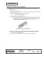
Thermal Label Printer
TM-L90
Specification
STANDARD
Rev. No.
E
Notes
Copied Date
,
,
Copied by
SEIKO EPSON CORPORATION
MATSUMOTO MINAMI PLANT
2070 KOTOBUKI KOAKA, MATSUMOTO-SHI, NAGANO, 399-8702 JAPAN
PHONE(0263)86-5353 FAX(0263)86-9925
Confidential
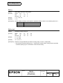
REVISION SHEET
Sheet 1 of 9
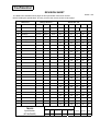
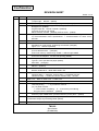
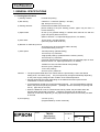
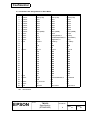
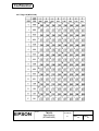
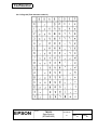
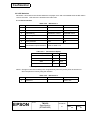
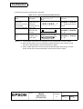
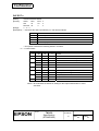
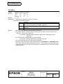
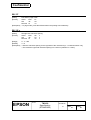
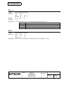
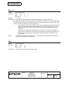
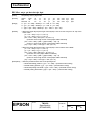
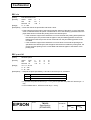
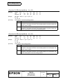
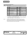
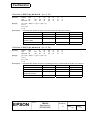
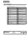
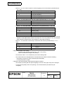
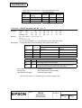
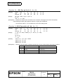
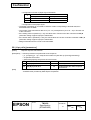
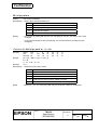
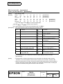
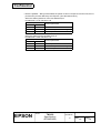
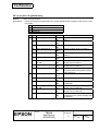
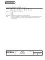
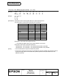
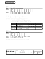
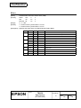
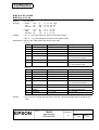
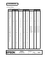
The table below indicates which pages in this specification have been revised.
Before reading this specification, be sure you have the correct version of each page.
Revisions
Rev.
Design Section
Document
Sheet Rev. No.
WRT
CHK
APL
Sheet
Rev. Sheet Rev.
Sheet
Rev.
A
Enactment
Hosomi
Ikegami
Takizawa
I
E
19
E
46
E
B
Change
Hosomi
Ikegami
Takizawa
II
E
20
E
47
E
C
Change
Hosomi
Ikegami
Godo
III
E
21
E
48
E
D
Change
Tsukada
−
Takizawa
IV
E
22
E
49
E
E
Change
Tsukada
−
Takizawa
V
E
23
E
50
E
VI
E
24
E
51
E
VII
E
25
E
52
E
26
E
53
E
27
E
54
E
TITLE
1
E
28
E
55
E
2
E
29
E
56
E
3
E
30
E
57
E
4
E
31
E
58
E
5
E
32
E
59
E
6
E
33
E
60
E
7
E
34
E
61
E
8
E
35
E
62
E
9
E
36
E
63
E
10
E
37
E
64
E
11
E
38
E
65
E
12
E
39
E
66
E
13
E
40
E
67
E
14
E
41
E
68
E
15
E
42
E
69
E
16
E
43
E
70
E
17
E
44
E
71
E
18
E
45
E
72
E
Front Part
TM-L90
Specification
Cover
Rev.
Sheet
Confidentiality
Agreement
General
Features
Table of
Contents
Contents
Appendix
Total
(STANDARD)
1
9
1
1
5
207
18
242
Confidential
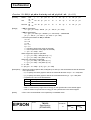
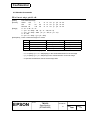
REVISION SHEET
Sheet 2 of 9
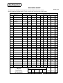
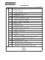
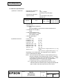
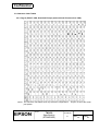
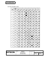
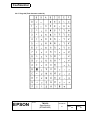
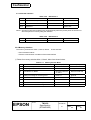
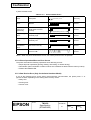
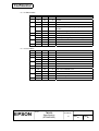
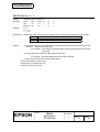
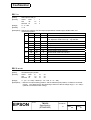
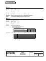
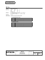
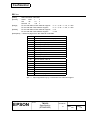
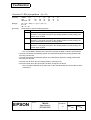
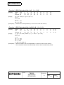
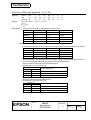
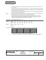
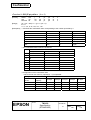
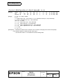
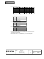
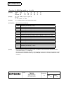
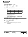
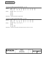
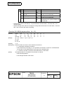
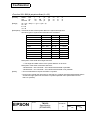
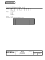
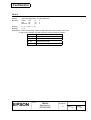
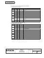
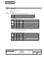
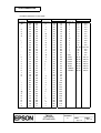
The table below indicates which pages in this specification have been revised.
Before reading this specification, be sure you have the correct version of each page.
Revisions
Rev.
Document
Design Section
WRT
CHK
Sheet Rev. No.
APL
Sheet
Rev. Sheet Rev.
Sheet
Rev.
A
Enactment
73
E
100
E
127
E
B
Change
74
E
101
E
128
E
C
Change
75
E
102
E
129
E
D
Change
76
E
103
E
130
E
E
Change
77
E
104
E
131
E
78
E
105
E
132
E
79
E
106
E
133
E
80
E
107
E
134
E
81
E
108
E
135
E
82
E
109
E
136
E
83
E
110
E
137
E
84
E
111
E
138
E
85
E
112
E
139
E
86
E
113
E
140
E
87
E
114
E
141
E
88
E
115
E
142
E
89
E
116
E
143
E
90
E
117
E
144
E
91
E
118
E
145
E
92
E
119
E
146
E
93
E
120
E
147
E
94
E
121
E
148
E
95
E
122
E
149
E
96
E
123
E
150
E
97
E
124
E
151
E
98
E
125
E
152
E
99
E
126
E
153
E
TITLE
Front Part
TM-L90
Specification
Cover
Rev.
Sheet
Confidentiality
Agreement
General
Features
Table of
Contents
Contents
Appendix
Total
(STANDARD)
1
9
1
1
5
207
18
242
Confidential
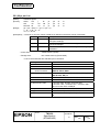
REVISION SHEET
Sheet 3 of 9
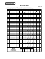
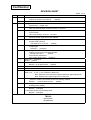
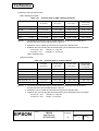
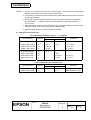
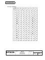
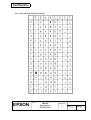
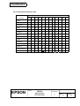
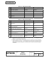
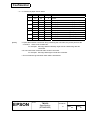
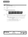
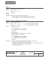
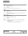
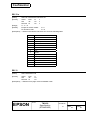
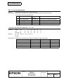
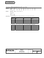
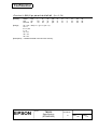
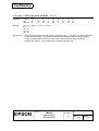
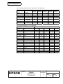
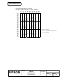
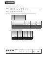
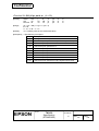
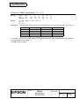
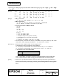
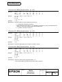
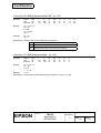
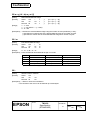
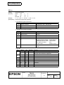
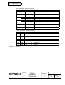
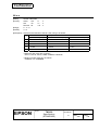
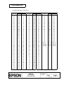
The table below indicates which pages in this specification have been revised.
Before reading this specification, be sure you have the correct version of each page.
Revisions
Rev.
Document
Design Section
WRT
CHK
Sheet Rev. No.
APL
Sheet
Rev. Sheet Rev.
Sheet
Rev.
A
Enactment
154
E
181
E
App.1
E
B
Change
155
E
182
E
App.2
E
C
Change
156
E
183
E
App.3
E
D
Change
157
E
184
E
App.4
E
E
Change
158
E
185
E
App.5
E
159
E
186
E
App.6
E
160
E
187
E
App.7
E
161
E
188
E
App.8
E
162
E
189
E
App.9
E
163
E
190
E
App.10
E
164
E
191
E
App.11
E
165
E
192
E
App.12
E
166
E
193
E
App.13
E
167
E
194
E
App.14
E
168
E
195
E
App.15
E
169
E
196
E
App.16
E
170
E
197
E
App.17
E
171
E
198
E
App.18
E
172
E
199
E
173
E
200
E
174
E
201
E
175
E
202
E
176
E
203
E
177
E
204
E
178
E
205
E
179
E
206
E
180
E
207
E
TITLE
Front Part
TM-L90
Specification
Cover
Rev.
Sheet
Confidentiality
Agreement
General
Features
Table of
Contents
Contents
Appendix
Total
(STANDARD)
1
9
1
1
5
207
18
242
Confidential
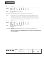
REVISION SHEET
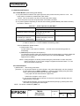
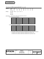
Sheet 4 of 9
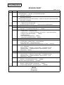
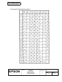
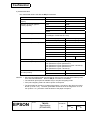
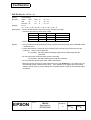
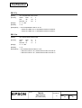
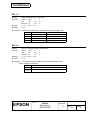
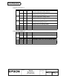
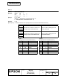
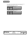
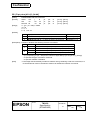
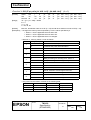
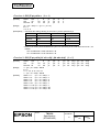
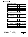
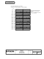
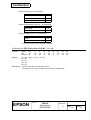
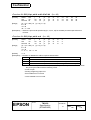
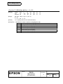
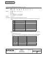
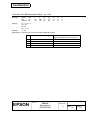
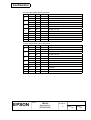
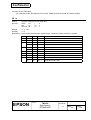
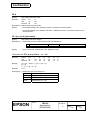
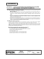
REV.
SHEET
B
7
8
9
C
All
I
II
III-VII
1
2
3
4
5
6
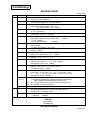
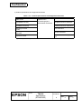
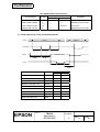
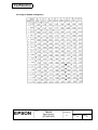
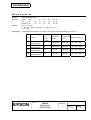
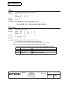
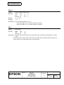
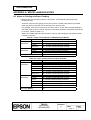
CHANGED CONTENTS
1.6 Paper Specifications
5) Specified paper → Type No. of the specified roll paper
Description (changed)
6) Substitution paper → Usable paper
Description (changed)
7) Recommended two-color thermal paper → Notes on using two-color thermal paper
Description (changed)
10) High-speed print mode
→ Papers to use for high speed
The high-speed print mode can ….. → If the one of the following types …..
All pages are renumbered, since one page is deleted.
Trademarks
Windows is a registered trademark of … (added)
General Features
• Ticket printing → Receipt printing
• Normal mode → Normal printing, High-speed mode → High-speed printing
• Using two-color thermal paper, … (added)
• UB-S03 (deleted)
• Environment-friendly design … (added)
• Using with the EPSON PS-180 … (added)
Table of Contents (changed)
1.1 Printing Specifications
7) Print speed: Normal mode → Normal printing,
High-speed mode → High-speed printing,
<Ladder bar code, two-dimensional code printing> 70 mm/s → 90 mm/s
1.2 Character Specifications
1), 2) (changed)
Japanese Kanji → Japanese, Chinese Kanji → Simplified Chinese,
Taiwanese Kanji → Traditional Chinese, Thai characters → Thai,
Korean Kanji → Korean
Table 1.2.1, 1.2.2 NOTES 3. (added)
Table 1.2.3,
Japanese Kanji → Japanese, Chinese Kanji → Simplified Chinese,
Taiwanese Kanji → Traditional Chinese, Thai characters → Thai,
Korean Kanji → Korean
1.3 Autocutter
NOTES: • The cutting type must be … (added)
1.4 Function of the Paper Detectors
(changed)
1.5 Paper Roll Supply Device
NOTES: • When the paper roll diameter … (added)
3) Paper width selection 38 mm or 60 mm … (deleted)
TITLE
TM-L90
Specification
(STANDARD)
Confidential
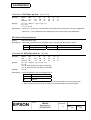
REVISION SHEET
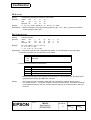
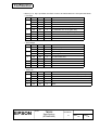
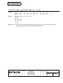
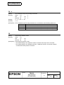
Sheet 5 of 9
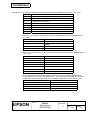
REV.
SHEET
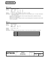
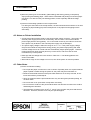
CHANGED CONTENTS
C
7
1.6 Page Specifications
1) Paper type: NOTES (added)
5) Usable paper → Specified roll paper type No. (changed)
6) Specified original paper type No. (changed)
Roll paper No. (added)
Original Paper No. 140LAB, 130LAB-1 (deleted)
10) Paper to use for high speed
HD75, HG76B, 140LAD (deleted), ENTLA series (added)
11) Recommended label specifications → Requirement for label length
12) Recommended ticket specifications → Recommended for black mark
intervals
13) Recommended for black mark position (added)
8
9
10
11
12, 13
14
15
16
31
33
37
58
59
65
67
68
69
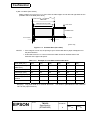
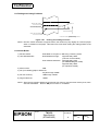
1.7 Printable Area
Printable area, right margin, positioning dot number (changed)
Figure 1.7.1 tolerance (deleted)
1.9 Internal Buffer
2) User-defined buffer: (changed)
5) NV user memory: 1KB through 129KB → 1KB through 192KB
1.10 Electrical Characteristics
2) Current consumption for two-color printing (added)
1.12 Reliability
Type No. of the specified roll paper (added)
Autocutter (changed)
2.1.3 Other Interfaces
UB-S03 (deleted)
2.2.3 Drawer Kick-out Connector
MOLEX 52065-6615 → DDK 285D-7660J-100
Kanji command list
Japanese Kanji → Japanese, Chinese Kanji → Simplified Chinese,
Taiwanese Kanji → Traditional Chinese, Korean Kanji → Korean
Table 3.3.2, Refer to Table 3.3.2 → Table 3.3.3
Table 3.3.7, Bit 2: Large → 4KB, Small → 45 bytes
3.5 Self-test
”Self-test printing, …” → “If you want to continue …”
(*2) • A partial cut after …
→ • Autocut after completing … & • Feed to the print starting …
… and goes into the standard … (deleted)
3.7 Memory Switch Setting Mode
Press the paper FEED button (located inside the printer) twice (added)
3.8 Automatic Paper Recognition Function (added)
3.9 Automatic Paper Layout Setting Mode (added)
3.9 Paper Detectors → Error Processing
TITLE
TM-L90
Specification
(STANDARD)
Confidential
REVISION SHEET
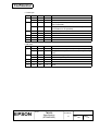
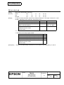
Sheet 6 of 9
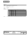
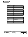
REV.
SHEET
C
71
73
74
75
76, 93,
101
84
90, 93
97
121
126,
129
131
133
139 141
154,
156
157
160 173
182
187
197
CHANGED CONTENTS
3.9 Cover Open Button → 3.11
3.10 Cover Open Sensor → 3.12
3.11 Print Buffer-full Printing → 3.13
(in page mode) (added)
5.1 Standard Acccessories
• External power supply unit (added)
6.2 Explanation of Terms
2) Printable area (changed)
6) Paper layout (added)
LF, ESC J, ESC d
[Description] • If the paper layout … (added)
DLE DC4
[Notes] • …JavaPOS driver … (added)
ESC 3, ESC J
[Notes] • 1016 mm {40”} → 900 mm {35.5”}
ESC W
[Default] (changed)
GS ( E <Function 3>
[Default] Msw 2-1 (deleted)
Specified single-color paper → Single-color paper
Recommended two-color paper → Two-color paper
GS ( E <Function 8>
[Range] 1 ≤ y ≤ 255 → y=2, y=3
GS ( E <Function 9>
[Range] 1 ≤ x ≤ 255 → x=2, x=3
GS ( E <Function 49 and 50>
(changed)
GS ( L <Function 67 and 112>
[Range] c=49, 50 (added)
GS ( M
[Description] 2-dimensional codes: <Function 165>, <Function 167>,
<Function 169>, and <Function 256> of GS ( k (added)
GS ( k (changed)
QRCode, MaxiCode (added)
GS V
[Notes] • If the printer cuts … (added)
GS a
[Description] Third byte Bit 1 and 2 is exchanged.
6.4 Kanji Control Commands
Japanese Kanji → Japanese, Chinese Kanji → Simplified Chinese,
Taiwanese Kanji → Traditional Chinese, Korean Kanji → Korean
TITLE
TM-L90
Specification
(STANDARD)
Confidential
REVISION SHEET
Sheet 7 of 9
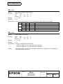
REV.
SHEET
C
App.3
App.15
D
All
II
1
2
6
7
9
11
12
13
59
60
61
67
68
CHANGED CONTENTS
A.3 Other Notes
• When the printer is not used for …
APPENDIX I: (added)
(added)
All pages are revised.
monochrome → single-color
General Features
Two-color thermal paper printing: 50 mm/s → 90 mm/s
1.1 Printing Specifications
7) Print speed
<two-color printing> 50 mm/s → 90 mm/s
1.2 Character Specifications
Japanese model: Special font table (added)
1.5 Paper Roll Supply Device
3) Paper width selection
The range of 71 to 79 mm ….. (added)
1.6 Paper Specification
1) Paper type
NOTES: 2. (changed)
1.6 Paper Specification
7) Notes on using two-color thermal paper
• Printing with Color 2 ….. (added)
9 Print density adjustment
If the density levels shown … (deleted)
Figure 1.6.3 (changed)
NOTES: (added)
1.7 Printable Area
NOTES: • A roll paper which …. (added)
NOTES:• A label paper which ….. (added)
Table 3.3.7,
Table 3.3.8,
Table 3.3.9,
0→48, 1→49
0→48, 1→49, Undefined→Reserved
0→48, 1→49, Undefined→Reserved,
Bit 4: Selection of the maximum length of automatic paper adjustment
Bit 5: Enables left or right margin for bar code print
2) Customized value
Selection of black-color density in two-color printing. (added)
NOTES: ….. because the thickness ….. (added)
3.7 Memory Switch Setting Mode
8) Setting label (added)
3.8 Automatic Paper Recognition Function
NOTES: (changed)
3.9 Automatic Paper Layout Setting Mode
NOTES: (changed)
TITLE
TM-L90
Specification
(STANDARD)
Confidential
REVISION SHEET
Sheet 8 of 9
REV.
D
SHEET
69
73
95
118
122
126
127, 130
131
141
174
182
165
166
App.13∼
App.14
App.17
E
All
II
CHANGED CONTENTS
Table 3.10.1 Automatically Recoverable Errors
Paper layout error (deleted)
5.1 Standard Accessories
Eternal power supply unit PS-175 (deleted)
ESC R
[Default] Except for Korean model: n=0
For Korean model: n=13 (added)
GS ( E
fn = 49 (changed)
GS ( E <Function 3>
In table for a = 8, bit 4, 5 (added)
GS ( E <Function 5>
[Description] Total 43 kinds of paper width ….. (added)
a = 118 (added)
• The density of printing
….. (added)
GS ( E <Function 6>
a=118 (added)
70→Light, 85→Medium, 100→Dark
GS ( K
[Notes] (added)
GS ( E <Function 49>
[Notes] • The paper which has ….. (added)
GS ∗
[Range] 1 ≤ y ≤ 48 → 1 ≤ y ≤ 46
GS V
[Range] ➂ m=103, 104,
0 ≤ n ≤ 255 (added)
[Description] m=103, 104 (added)
GS g 0
[Range] 20 ≤ n ≤ 70 → nL = 20, 21, 50, 70
[Description] [Units] (added)
GS g 2
[Range] 20 ≤ (nL+nH×254) ≤ 70 → 20 ≤ (nL+nH×254) ≤ 198
20 ≤ n ≤ 70 → nL = 20, 21, 50, 70, 148, 149, 178, 198
[Description] [Units] (added)
APPENDIX G. NOTES ON TURNING THE PRINTING POWER OFF
→ NOTES ON UPDATING THE MAINTENANCE COUNTER
AND TURNING THE PRINTER’S POWER OFF
G.1 → G.2.1 Printer setup control by the host with printer power off
G.2 → G.2.2 Power off control by the host
APPENDIX J (added)
All pages are revised.
The description about die-cut label are newly added.
printer cover → roll paper cover
General Description
… UB-U05 … (added)
TITLE
TM-L90
Specification
(STANDARD)
REVISION SHEET
Sheet 9 of 9
Confidential
REV.
SHEET
E
5
8
9
15
16
31
36
37
59
60
62
63
69
71
74
79
82
144 - 147
148
149
207
App.8
CHANGED CONTENTS
1.3 Autocutter
1) Cutting method
(added)
1.6 Paper Specifications
F5041 (added)
7) Notes on using two-color thermal paper
• Make sure to use the specified … (added)
1.11 EMI and Safety Standards Applied
PS-175 (deleted)
1.12 Reliability
1) Life Autocutter: (changed)
2.1.3 Other Interfaces
… UB-U05 … (added)
3.1 List of Commands
GS ( H (added)
GS v (moved to “Obsolete commands”)
Table 3.3.5 DIP Switch 1
SW1 bit 2 (changed)
Table 3.3.8 Memory Switch Msw 2
SW bit 1 (changed)
Table 3.3.9 Memory Swtich Msw8
SW bit 2 (added), SW bit 3 (changed)
3) Communication conditions of the serial interface
NOTE: (added)
3.4.1 Panel LEDs
Flashing pattern: Approximately 160 ms → Approximately 320 ms
3.10 Paper Setting Clear Mode for Paper Layout (added)
Table 3.11.1 Automatically Recoverable Errors
Print head high temperature error (changed)
3.11.2 Printer Operation When an Error Occurs
… (printing, feeding, … ) (added)
… (When the BUSY … ) (changed)
5.2 Options
… UB-U05 … (added)
DLE EOT
[Description] NOTE (added)
DLE ENQ
[Notes] (added)
GS ( H (added)
GS ( K < Function 48>
[Note] (added)
GS ( K < Function 49>
[Note] (added)
6.5 Obsolete Commands (added)
APPENDIX E: MAINTENANCE (added)
TITLE
TM-L90
Specification
(STANDARD)
Confidential
CONFIDENTIALITY AGREEMENT
BY USING THIS DOCUMENT, YOU AGREE TO ABIDE BY THE TERMS OF THIS AGREEMENT. PLEASE
RETURN THIS DOCUMENT IMMEDIATELY IF YOU DO NOT AGREE TO THESE TERMS.
1. This document contains confidential, proprietary information of Seiko Epson Corporation or its affiliates.
You must keep such information confidential. If the user is a business entity or organization, you must
limit disclosure to those of your employees, agents, and contractors who have a need to know and who
are also bound by obligations of confidentiality.
2. On the earlier of (a) termination of your relationship with Seiko Epson, or (b) Seiko Epson's request, you
must stop using the confidential information. You must then return or destroy the information, as
directed by Seiko Epson.
3. If a court, arbitrator, government agency, or the like orders you to disclose any confidential information,
you must immediately notify Seiko Epson. You agree to give Seiko Epson reasonable cooperation and
assistance in the negotiation.
4. You may use confidential information only for the purpose of operating or servicing the products to which
the document relates, unless you obtain the prior written consent of Seiko Epson for some other use.
5. Seiko Epson warrants that it has the right to disclose the confidential information. SEIKO EPSON
MAKES NO OTHER WARRANTIES CONCERNING THE CONFIDENTIAL INFORMATION OR ANY
OTHER INFORMATION IN THE DOCUMENT, INCLUDING (WITHOUT LIMITATION) ANY
WARRANTY OF TITLE OR NON-INFRINGEMENT. Seiko Epson has no liability for loss or damage
arising from or relating to your use of or reliance on the information in the document.
6. You may not reproduce, store, or transmit the confidential information in any form or by any means
(electronic, mechanical, photocopying, recording, or otherwise) without the prior written permission of
Seiko Epson.
7. Your obligations under this Agreement are in addition to any other legal obligations. Seiko Epson does
not waive any right under this Agreement by failing to exercise it. The laws of Japan apply to this
Agreement.
Cautions
1. This document shall apply only to the product(s) identified herein.
2. No part of this document may be reproduced, stored in a retrieval system, or transmitted in any form or
by any means, electronic, mechanical, photocopying, recording, or otherwise, without the prior written
permission of Seiko Epson Corporation.
3. The contents of this document are subject to change without notice. Please contact us for the latest
information.
4. While every precaution has been taken in the preparation of this document, Seiko Epson Corporation
assumes no responsibility for errors or omissions.
5. Neither is any liability assumed for damages resulting from the use of the information contained herein.
6. Neither Seiko Epson Corporation nor its affiliates shall be liable to the purchaser of this product or third
parties for damages, losses, costs, or expenses incurred by the purchaser or third parties as a result of:
accident, misuse, or abuse of this product or unauthorized modifications, repairs, or alterations to this
product, or (excluding the U. S.) failure to strictly comply with Seiko Epson Corporation's operating and
maintenance instructions.
7. Seiko Epson Corporation shall not be liable against any damages or problems arising from the use of
any options or any consumable products other than those designated as Original EPSON Products or
EPSON Approved Products by Seiko Epson Corporation.
Trademarks
®
®
EPSON and ESC/POS are registered trademarks of Seiko Epson Corporation.
General Notice: Other product and company names used herein are for identification purposes only and may
be trademarks of their respective companies.
TITLE
EPSON
TM-L90
Specification
(STANDARD)
SHEET
REVISION
E
NO.
NEXT
SHEET
II
I
Confidential
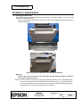
GENERAL FEATURES
1) This specification applies to the following models of the TM-L90 series printer:
TM-L90
(with serial interface)
TM-L90P
(with parallel interface)
* This specification describes only the outline of the general functions and the model-dependent
functions of the commands. For detailed specifications and usage of the commands, please refer to
the ESC/POS APG (Application Programming Guide) that is separately issued.
2) Features
The TM-L90 series printer has the following features:
<Printing>
• Label printing is possible. (Die-cut label paper)
Die-cut label paper:
Label paper that has a predefined size of labels with an interval
between labels.
• Continuous label printing is possible.
Continuous label paper: Label roll paper without labels die-cut in predefined sizes and
label length is variable with an autocutter.
• Receipt printing is possible (thickness: 145 µm).
• High-speed printing is possible.
Normal printing:
120 mm/s {4.72"/s} maximum
High-speed printing:
150 mm/s {5.91"/s} maximum
• Using two-color thermal paper, two-color printing is possible (print speed: 90 mm/s {3.54"/s}
maximum).
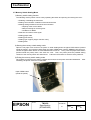
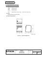
<Printer handling>
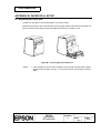
• The printer can be placed vertically (standard) or horizontally on a table, and hung vertically
on a wall.
• Easy drop-in paper loading.
• Cable connectors are housed in the bottom of the printer.
<Software>
• Command protocol is based on the ESC/POS Proprietary Command System.
®
• OPOS ADK and Windows printer drivers are available.
®
• Printing of various bar codes is possible.
QRCode) are supported.
Two-dimensional codes (PDF417, MaxiCode,
• Various layouts are possible by using page mode.
<General>
• Various interface boards (EPSON UB series, except UB-P02 and UB-U05) can be used.
• Using a paper roll spacer, various width papers can be used (38 mm to 70 mm {1.5 to
2.76"}) by adjustment of the paper roll spacer.
• Can use a paper roll with up to 90 mm {3.5"} diameter.
• Environment-friendly design reduces the power consumption in standby mode (compared to
the EPSON’s legacy models: approximately 1/2).
• Using with the EPSON PS-180 power supply (power-saving type), the power consumption
for the printer and the AC adapter can be reduced by a large amount.
TITLE
EPSON
TM-L90
Specification
(STANDARD)
SHEET
REVISION
E
NO.
NEXT
SHEET
III
II
Confidential
Table of Contents
1. GENERAL SPECIFCATIONS ..............................................................................................................1
1.1 Printing Specifications....................................................................................................................1
1.2 Character Specifications ................................................................................................................2
1.3 Autocutter.......................................................................................................................................5
1.4 Function of the Paper Detectors ....................................................................................................5
1.5 Paper Roll Supply Device ..............................................................................................................6
1.6 Paper Specifications ......................................................................................................................7
1.7 Printable Area ..............................................................................................................................12
1.8 Printing and Cutting Positions ......................................................................................................14
1.9 Internal Buffer ..............................................................................................................................14
1.10 Electrical Characteristics............................................................................................................15
1.11 EMI and Safety Standards Applied ............................................................................................15
1.12 Reliability....................................................................................................................................16
1.13 Environmental Conditions ..........................................................................................................17
1.14 Installation ..................................................................................................................................18
2. CONFIGURATION .............................................................................................................................19
2.1 Interface .......................................................................................................................................19
2.1.1 RS-232 Serial Interface .......................................................................................................19
2.1.2 IEEE 1284 Bidirectional Parallel Interface (Parallel Interface Specifications) .....................25
2.1.3 Other Interfaces...................................................................................................................31
2.2 Connectors...................................................................................................................................32
2.2.1 Interface Connectors ...........................................................................................................32
2.2.2 Power Supply Connector .....................................................................................................32
2.2.3 Drawer Kick-out Connector (Modular Connector) ...............................................................33
3. FUNCTIONS.......................................................................................................................................35
3.1 List of Commands........................................................................................................................35
3.2 Character Code Tables................................................................................................................38
3.2.1 Page 0 (PC437: USA, Standard Europe) (International Character Set: USA) ....................38
3.2.2 Page 1 (Katakana)...............................................................................................................39
3.2.3 Page 2 (PC850: Multilingual) ...............................................................................................40
3.2.4 Page 3 (PC860: Portuguese) ..............................................................................................41
3.2.5 Page 4 (PC863: Canadian-French) .....................................................................................42
3.2.6 Page 5 (PC865: Nordic) ......................................................................................................43
3.2.7 Page 16 (WPC1252) ...........................................................................................................44
3.2.8 Page 17 (PC866: Cyrillic #2) ...............................................................................................45
3.2.9 Page 18 (PC852: Latin2) .....................................................................................................46
3.2.10 Page 19 (PC858) ...............................................................................................................47
3.2.11 Page 20 (Thai character code 42) .....................................................................................48
3.2.12 Page 21 (Thai character code 11) .....................................................................................49
3.2.13 Page 22 (Thai character code 13) .....................................................................................50
3.2.14 Page 23 (Thai character code 14) .....................................................................................51
3.2.15 Page 24 (Thai character code 16) .....................................................................................52
3.2.16 Page 25 (Thai character code 17) .....................................................................................53
3.2.17 Page 26 (Thai character code 18) .....................................................................................54
3.2.18 Page 255 (Space Page) ....................................................................................................55
3.2.19 International Character Sets ..............................................................................................56
3.3 Switches and Buttons ..................................................................................................................57
3.3.1 Power Button (Non-locking Push Button) ............................................................................57
3.3.2 Panel Buttons ......................................................................................................................57
3.3.3 DIP Switches .......................................................................................................................58
3.3.4 Memory Switches ................................................................................................................59
TITLE
EPSON
TM-L90
Specification
(STANDARD)
SHEET
REVISION
E
NO.
NEXT
SHEET
IV
III
Confidential
3.4 Indicators .....................................................................................................................................63
3.4.1 Panel LEDs..........................................................................................................................63
3.5 Self-test........................................................................................................................................65
3.6 Hexadecimal Dumping.................................................................................................................66
3.7 Memory Switch Setting Mode ......................................................................................................67
3.8 Automatic Paper Recognition Function........................................................................................68
3.10 Paper Setting Clear Mode for Paper Layout ..............................................................................69
3.11 Error Processing ........................................................................................................................69
3.11.1 Error Types ........................................................................................................................69
3.11.2 Printer Operation When an Error Occurs ..........................................................................71
3.11.3 Data Receive Error (Only for the Serial Interface Model) ..................................................71
3.12 Cover Open Button ....................................................................................................................72
3.13 Cover Open Sensor ...................................................................................................................72
3.14 Print Buffer-full Printing ..............................................................................................................72
4.1 External Dimensions and Mass ...................................................................................................73
4.2 Color ............................................................................................................................................73
4.3 External Appearance ...................................................................................................................73
5.1 Standard Accessories ..................................................................................................................74
5.2 Options.........................................................................................................................................74
5.3 Consumables ...............................................................................................................................74
6. COMMANDS ......................................................................................................................................75
6.1 Command Notation ......................................................................................................................75
6.2 Explanation of Terms ...................................................................................................................75
6.3 Control Commands ......................................................................................................................77
HT .................................................................................................................................................77
LF..................................................................................................................................................77
FF .................................................................................................................................................77
CR.................................................................................................................................................78
CAN ..............................................................................................................................................78
DLE EOT n ...................................................................................................................................79
DLE ENQ n ...................................................................................................................................82
DLE DC4 fn m t (fn = 1) ................................................................................................................83
DLE DC4 fn a b (fn = 2) ................................................................................................................84
DLE DC4 fn d1…d7 (fn = 8) .........................................................................................................85
ESC FF .........................................................................................................................................86
ESC SP n......................................................................................................................................86
ESC ! n .........................................................................................................................................87
ESC $ nL nH.................................................................................................................................87
ESC % n .......................................................................................................................................88
ESC & y c1 c2 [x1 d1...d(y×1)]...[xk d1...d(yxk)]...........................................................................88
ESC ∗ m nL nH d1...dk .................................................................................................................89
ESC - n .........................................................................................................................................90
ESC 2 ...........................................................................................................................................90
ESC 3 n ........................................................................................................................................91
ESC = n ........................................................................................................................................91
ESC ? n ........................................................................................................................................92
ESC @..........................................................................................................................................92
ESC D n1...nk NUL.......................................................................................................................92
ESC E n ........................................................................................................................................93
ESC G n........................................................................................................................................93
TITLE
EPSON
TM-L90
Specification
(STANDARD)
SHEET
REVISION
E
NO.
NEXT
SHEET
V
IV
Confidential
ESC J n.........................................................................................................................................94
ESC L ...........................................................................................................................................94
ESC M n .......................................................................................................................................95
ESC R n........................................................................................................................................96
ESC S ...........................................................................................................................................96
ESC T n ........................................................................................................................................97
ESC V n ........................................................................................................................................97
ESC W xL xH yL yH dxL dxH dyL dyH.........................................................................................98
ESC \ nL nH..................................................................................................................................99
ESC a n ........................................................................................................................................99
ESC c 3 n....................................................................................................................................100
ESC c 4 n....................................................................................................................................101
ESC c 5 n....................................................................................................................................101
ESC d n ......................................................................................................................................102
ESC p m t1 t2 .............................................................................................................................102
ESC t n .......................................................................................................................................103
ESC { n .......................................................................................................................................104
FS ( L pL pH fn [parameters] ......................................................................................................105
<Function 48> FS ( L pL pH fn m (fn = 48) ..............................................................................105
<Function 65> FS ( L pL pH fn m (fn = 65) ..............................................................................107
<Function 66> FS ( L pL pH fn m (fn = 66) ..............................................................................107
<Function 67> FS ( L pL pH fn m (fn = 67) ..............................................................................108
GS ! n .........................................................................................................................................109
GS $ nL nH .................................................................................................................................110
GS ( A pL pH n m .......................................................................................................................110
GS ( C pL pH m fn b [c1 c2] [d1...dk]..........................................................................................111
<Function 0> GS ( C pL pH m fn b c1 c2 (fn = 0, 48) ..............................................................112
<Function 1> GS ( C pL pH m fn b c1 c2 d1...dk (fn = 1, 49) ..................................................112
<Function 2> GS ( C pL pH m fn b c1 c2 (fn = 2, 50) ..............................................................113
<Function 3> GS ( C pL pH m fn b (fn = 3, 51) ........................................................................115
<Function 4> GS ( C pL pH m fn b (fn = 4, 52) ........................................................................115
<Function 5> GS ( C pL pH m fn b (fn = 5, 53) ........................................................................116
<Function 6> GS ( C pL pH m fn b d1 d2 d3 (fn = 6, 54) .........................................................117
GS ( D pL pH m [a1 b1]...[ak bk] ................................................................................................118
GS ( E pL pH fn [parameters] .....................................................................................................119
<Function 1> GS ( E pL pH fn d1 d2 (fn = 1) ...........................................................................120
<Function 2> GS ( E pL pH fn d1 d2 d3 (fn = 2) ......................................................................121
<Function 3> GS ( E pL pH fn [a1 b18...b11]...[ak bk8...bk1] (fn = 3)......................................122
<Function 4> GS ( E pL pH fn a (fn = 4) ..................................................................................124
<Function 5> GS ( E pL pH fn [a1 n1L n1H]...[ak nkL nkH] (fn = 5) ........................................124
<Function 6> GS ( E pL pH fn a (fn = 6) ..................................................................................128
<Function 7> GS ( E pL pH fn a d1 d2 (fn = 7) ........................................................................131
<Function 8> GS ( E pL pH fn y c1 c2 [x d1...d(y × x)]k (fn = 8) ..............................................132
<Function 9> GS ( E pL pH fn x c1 c2 [y d1...d(x × y)]k (fn = 9) ..............................................134
<Function 10> GS ( E pL pH fn c1 c2 (fn = 10) .......................................................................136
<Function 11> GS ( E pL pH fn a d1...dk (fn = 11) ..................................................................136
<Function 12> GS ( E pL pH fn a (fn = 12) ...........................................................................138
<Function 48> GS ( E pL pH fn d1 d2 d3 (fn = 48) ..................................................................139
<Function 49> GS ( E pL pH fn sa; sb; sc; sd; se; sf; sg; sh; (fn = 49)....................................140
<Function 50> GS ( E pL pH fn n (fn = 50) ..............................................................................143
GS ( H pL pH fn [parameters].....................................................................................................144
<Function 48> GS ( H pL pH fn m d1 d2 d3 d4 (fn = 48) .........................................................145
<Function 49> GS ( H pL pH fn m d (fn = 49) ..........................................................................145
TITLE
EPSON
TM-L90
Specification
(STANDARD)
SHEET
REVISION
E
NO.
NEXT
SHEET
VI
V
Confidential
GS ( K pL pH fn m ......................................................................................................................148
<Function 48> GS ( K pL pH fn m (fn = 48) .............................................................................148
<Function 49> GS ( K pL pH fn m (fn = 49) .............................................................................149
<Function 50> GS ( K pL pH fn m (fn = 50) .............................................................................150
<Function 97> GS ( K pL pH fn m (fn = 97) .............................................................................151
GS ( L pL pH m fn [parameters] GS 8 L p1 p2 p3 p4 m fn [parameters]...............................152
<Function 48> GS ( L pL pH m fn (fn = 0, 48)..........................................................................153
<Function 50> GS ( L pL pH m fn (fn = 2, 50)..........................................................................153
<Function 51> GS ( L pL pH m fn (fn = 3, 51)..........................................................................154
<Function 64> GS ( L pL pH m fn d1 d2 (fn = 64)....................................................................155
<Function 65> GS ( L pL pH m fn d1 d2 d3 (fn = 65)...............................................................157
<Function 66> GS ( L pL pH m fn kc1 kc2 (fn = 66) ................................................................157
<Function 67> GS ( L pL pH m fn a kc1 kc2 b xL xH yL yH [c d1....dk]1… [c d1....dk] ..............158
<Function 69> GS ( L pL pH m fn kc1 kc2 x y (fn = 69)...........................................................159
<Function 112> GS ( L pL pH m fn a bx by c xL xH yL yH d1…dk (fn = 112) .........................160
GS ( M pL pH fn m......................................................................................................................161
<Function 1> GS ( M pL pH fn m (fn = 1,49)............................................................................162
<Function 2> GS ( M pL pH fn m (fn = 2,50)............................................................................162
<Function 3> GS ( M pL pH fn m (fn = 3, 51)...........................................................................163
GS ( N pL pH fn [parameters].....................................................................................................163
<Function 48> GS ( N pL pH fn m (fn = 48) .............................................................................163
GS ( k pL pH cn fn [parameters].................................................................................................164
GS ( k pL pH cn fn m ..................................................................................................................164
GS ( k pL pH cn fn m ..................................................................................................................164
<Function 065> GS ( k pL pH cn fn n (fn = 65)........................................................................165
<Function 066> GS ( k pL pH cn fn n (fn = 66)........................................................................166
<Function 067> GS ( k pL pH cn fn n (fn = 67)........................................................................166
<Function 068> GS ( k pL pH cn fn n (fn = 68)........................................................................166
<Function 069> GS ( k pL pH cn fn m n (fn = 69)....................................................................167
<Function 070> GS ( k pL pH cn fn m (fn = 70) .........................................................................168
<Function 080> GS ( k pL pH cn fn m d1…dk (fn = 80) ..........................................................168
<Function 081> GS ( k pL pH cn fn m (fn = 81).......................................................................169
<Function 082> GS ( k pL pH cn fn m (fn = 82) .........................................................................170
<Function 165> GS ( k pL pH cn fn n1 n2 (fn = 65).................................................................171
<Function 167> GS ( k pL pH cn fn n (fn = 67)........................................................................171
<Function 169> GS ( k pL pH cn fn n (fn = 69)........................................................................172
<Function 180> GS ( k pL pH cn fn m d1…dk (fn = 80) ..........................................................173
<Function 181> GS ( k pL pH cn fn m (fn = 81).......................................................................173
<Function 182> GS ( k pL pH cn fn m (fn = 82).......................................................................174
<Function 265> GS ( k pL pH cn fn n (fn = 82)........................................................................175
<Function 280> GS ( k pL pH cn fn m d1…dk (fn = 80) ..........................................................176
<Function 281> GS ( k pL pH cn fn m (fn = 81).......................................................................176
<Function 282> GS ( k pL pH cn fn m (fn = 82).......................................................................177
GS ∗ x y [d1...d(x × y × 8)] ..........................................................................................................178
GS / m.........................................................................................................................................178
GS :.............................................................................................................................................178
GS B n ........................................................................................................................................179
GS C 0 n m .................................................................................................................................179
GS C 1 aL aH bL bH n r .............................................................................................................180
GS C 2 nL nH .............................................................................................................................180
GS C ; sa ; sb ; sn ; sr ; sc ;........................................................................................................181
GS H n ........................................................................................................................................182
GS I n..........................................................................................................................................183
TITLE
EPSON
TM-L90
Specification
(STANDARD)
SHEET
REVISION
E
NO.
NEXT
SHEET
VII
VI
Confidential
GS L nL nH .................................................................................................................................185
GS P x y .....................................................................................................................................185
GS T n ........................................................................................................................................186
➀ GS V m ➁ GS V m n ............................................................................................................186
GS W nL nH ...............................................................................................................................187
GS \ nL nH ..................................................................................................................................187
GS ^ r t m....................................................................................................................................188
GS a n.........................................................................................................................................189
GS b n.........................................................................................................................................192
GS c............................................................................................................................................192
GS f n .........................................................................................................................................193
GS g 0 m nL nH ..........................................................................................................................194
GS g 2 m nL nH ..........................................................................................................................195
GS h n.........................................................................................................................................196
➀ GS k m d1...dk NUL ➁ GS k m n d1...dn .............................................................................197
GS r n .........................................................................................................................................198
GS w n ........................................................................................................................................199
6.4 Kanji Control Commands ...........................................................................................................200
FS ! n ..........................................................................................................................................200
FS &............................................................................................................................................201
FS ( A pL pH fn [parameters]......................................................................................................201
<Function 48> FS ( A pL pH fn m (fn = 48)..............................................................................201
FS - n ..........................................................................................................................................202
FS . .............................................................................................................................................202
FS 2 c1 c2 d1...dk.......................................................................................................................203
FS C n.........................................................................................................................................205
FS S n1 n2..................................................................................................................................205
FS W n........................................................................................................................................206
6.5 Obsolete Commands .................................................................................................................207
GS v 0 m xL xH yL yH d1...dk ....................................................................................................207
APPENDIX A:
APPENDIX B:
APPENDIX C:
APPENDIX D:
APPENDIX E:
APPENDIX F:
APPENDIX G:
APPENDIX H:
MISCELLANEOUS NOTES ............................................................................... App.1
ROLL PAPER SETUP ....................................................................................... App.4
ADJUSTING THE PAPER ROLL NEAR-END SENSOR LOCATION ............... App.5
PRINT HEAD CLEANING.................................................................................. App.7
MAINTENANCE................................................................................................. App.8
NOTES ON USING THE DRAWER KICK-OUT CONNECTOR........................ App.9
CODE128 BAR CODE..................................................................................... App.10
NOTES ON UPDATING THE MAINTENANCE COUNTER
AND TURNING THE PRINTER’S POWER OFF............................................. App.14
APPENDIX I: NOTES ON PRINTING 2-DIMENSIONAL CODES ......................................... App.16
APPENDIX J: NOTES ON USING THE ABS STATUS .......................................................... App.17
APPENDIX K: NOTES ON SETTING MEMORY SWITCH 8-6 “FEEDING PAPER
TO THE PRINT STARTING POSITION AT POWER ON IS DISABLED” ....... App.18
TITLE
EPSON
TM-L90
Specification
(STANDARD)
SHEET
REVISION
E
NO.
NEXT
SHEET
1
VII
Confidential
1. GENERAL SPECIFCATIONS
1.1 Printing Specifications
1) Printing method:
Thermal line printing
2) Dot density:
8 dots/mm × 8 dots/mm (203 dpi × 203 dpi)
(dpi: dots per 25.4 mm {1"})
3) Printing direction:
Unidirectional forward with friction feed
(When feeding to the print starting position, paper may be fed in a
reverse direction.)
4) Paper width:
80 mm {3.15"} (default setting) or variable other than 80 mm with the
paper roll spacer packed in the box.
(Refer to Section 1.5, Paper Roll Supply Device, for details.)
5) Print width:
72 mm {2.83"}, 576 dot positions
(when the paper width is 80 mm)
6) Number of characters per line:
48 (using font A when the paper width is 80 mm)
(The default setting is font A)
7) Print speed:
<Normal printing> (default setting)
120 mm/s {4.72"} maximum
<High-speed printing> (selected with the memory switch)
150 mm/s {5.91"} maximum
(The high-speed printing is selected when the specified paper is used.
Refer to Section 1.6, Paper Specifications, for details.)
<Ladder bar code, two-dimensional code printing>
90 mm/s {3.54"} maximum
<Two-color printing>
90 mm/s {3.54"} maximum
NOTES: • The print speeds listed above are values when the print density is set to the default
setting at 24 V and 25°C {77°F}. The print speed may change automatically depending
on the power supply voltage and the condition of the head temperature.
• Printing speed may be slower depending on the data transmission speed and the
combination of control commands.
• Low transmission speed may cause intermittent printing. It is recommended to transmit
data to the printer as quickly as possible. (Example: at least 19,200 bps for printing with
font A) (bps: bits per second)
• When the ladder bar code or 2-dimensional code is printed, the print starts when the
specific paper feed speed is reached. Therefore, the paper may be fed for the
maximum 10 dot lines, depending on the paper feed speed at the time that the print data
is received.
8) Line spacing:
3.75 mm {0.15"}
(Programmable by control command.)
TITLE
EPSON
TM-L90
Specification
(STANDARD)
SHEET
REVISION
E
NO.
NEXT
SHEET
2
1
Confidential
1.2 Character Specifications
1) Number of characters:
Alphanumeric characters:
Extended graphics:
International characters:
95
128 × 11 pages
(including one space page)
37
Japanese model:
JIS (JIS X0208-1990): 6879
Special font:
Code System Number of Characters
JIS Code
Shift JIS Code
87-40 ∼ 87-9D
2D-21 ∼ 2D-7E
Special
845
ED-40 ∼ EE-FC
79-21 ∼ 7C-7E
FA-40 ∼ FC-4E
Multilingual character model supports printing with one of the following
character sets:
➀ Simplified Chinese (GB2312)
7580
(Using the GB5007 of the Chinese national standard font)
➁ Traditional Chinese (Big 5)
13494
➂ Thai (3-pass printing font)
128 characters × 7 pages
(133 character types)
➃ Korean (KS C5601)
8366
2) Character structure:
Font A (12 × 24):
Font B (9 × 17):
Font B (10 × 24):
Font C (8 × 16):
Kanji font A (24 × 24):
Kanji font B (20 × 24):
Kanji font C (16 × 16):
Thai (12 × 72):
12 × 24
9 × 17
10 × 24
8 × 16
24 × 24
20 × 24
16 × 16
12 × 72
Thai (9 × 51):
9 × 51
(When the font is configured with Font A (12 × 24))
(When the font is configured with Font B (9 × 17))
Depending on the model types, the supported fonts are different.
Font A is selected as the default.
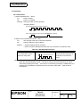
NOTE: Thai fonts built into this printer are 3-pass printing fonts (*1)
that are combined in three different parts, shown in character
code pages 20 through 26 for the alphanumeric fonts. There
are two kinds of Thai fonts: font A (12 × 72) with 3-pass
printing and font B (9 × 51) with 3-pass printing.
(*1): 3-pass printing is the printing method to print one Thai
character with three character parts configured vertically with
upper, middle, and lower parts sent from the host PC.
TITLE
EPSON
TM-L90
Specification
(STANDARD)
SHEET
REVISION
E
NO.
NEXT
SHEET
3
2
Confidential
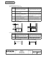
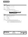
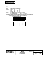
3) Character size (Character area):
<ANK / Multilingual model>
Table 1.2.1
Character Size for ANK / Multilingual Model
Standard
W×H (mm)
Double-height
W×H (mm)
Double-width
W×H (mm)
Double-width /
Double-height
W×H (mm)
Font A
12 × 24
1.50 × 3.0
1.50 × 6.0
3.0 × 3.0
3.0 × 6.0
Font B
9 × 17
1.13 × 2.13
1.13 × 4.25
2.25 × 2.13
2.25 × 4.25
Kanji font A
24 × 24
3.0 × 3.0
3.0 × 6.0
6.0 × 3.0
6.0 × 6.0
Thai
12 × 72
1.50 × 9.0
1.50 × 18.0
3.0 × 9.0
3.0 × 18.0
Thai
9 × 51
1.13 × 6.38
1.13 × 12.75
2.25 × 6.38
2.25 × 12.75
NOTES: 1. The actual print character may be smaller than the size shown in the table above,
because the above size includes spaces in the font.
2. Characters can be scaled up to 64 times as large as the standard size.
3. Character size not including the horizontal spacing in the standard scale is as follows:
Font A (12 × 24):
Font B (9 × 17):
1.25 (W) × 3.0 (H) mm
0.88 (W) × 2.13 (H) mm
(ANK = alphanumeric)
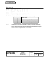
<Japanese model>
Table 1.2.2
Character Size for Japanese Model
Standard
W×H (mm)
Double-height
W×H (mm)
Double-width
W×H (mm)
Double-width /
Double-height
W×H (mm)
Font A
12 × 24
1.50 × 3.0
1.50 × 6.0
3.0 × 3.0
3.0 × 6.0
Font B
10 × 24
1.25 × 3.0
1.25 × 6.0
2.5 × 3.0
2.5 × 6.0
Font C
8 × 16
1.0 × 2.0
1.0 × 4.0
2.0 × 2.0
2.0 × 4.0
Kanji font A 24 × 24
3.0 × 3.0
3.0 × 6.0
6.0 × 3.0
6.0 × 6.0
Kanji font B 20 × 24
2.5 × 3.0
2.5 × 6.0
5.0 × 3.0
5.0 × 6.0
Kanji font C 16 × 16
2.0 × 2.0
2.0 × 4.0
4.0 × 2.0
4.0 × 4.0
NOTES: 1. The actual print character may be smaller than the size shown in the table above,
because the above size includes spaces in the font.
2. Characters can be scaled up to 64 times as large as the standard size.
3. Character size not including the horizontal spacing in the standard scale is as follows:
Font A (12 × 24):
Font B (10 × 24):
1.25 (W) × 3.0 (H) mm
1.0 (W) × 3.0 (H) mm
TITLE
EPSON
TM-L90
Specification
(STANDARD)
SHEET
REVISION
E
NO.
NEXT
SHEET
4
3
Confidential
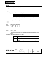
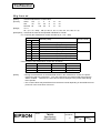
4) Product specifications and supported characters
Table 1.2.3 Product Specifications and Supported Characters
Product Specifications
Supported Characters
• Alphanumeric
ANK model
--• Extended graphics
Multilingual model
Simplified Chinese characters
(Simplified Chinese)
• International characters
Multilingual model
Traditional Chinese characters
(Traditional Chinese)
Multilingual model
(Thai)
Thai characters
Multilingual model
(Korean)
Korean characters
Japanese model
Japanese characters, Special
font
(ANK = alphanumeric)
TITLE
EPSON
TM-L90
Specification
(STANDARD)
SHEET
REVISION
E
NO.
NEXT
SHEET
5
4
Confidential
1.3 Autocutter
1) Cutting method:
By separated-blade scissor
2) Cutting type:
Full cut (cuts paper completely) (default setting)
Partial cut (one point left uncut) is also available as a dealer option.
(Set by changing the position of the autocutter unit.)
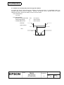
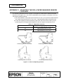
NOTES: • Install the paper exit guide packed in the box with the printer when the autocutter is
used with a full cut, positioning the printer horizontally. If the printer is installed
horizontally without the paper exit guide, and the autocutter full cut is used, a cut
sheet may drop in the paper path, and it may cause a double-cut, paper jam, or
autocutter error. However, if the printer is installed vertically or if the autocutter is
used with a partial cut, the paper exit guide does not have to be used.
• After cutting, paper must be fed approximately 1 mm {16/406"} or more, then be
stopped, because if it is not, paper may be jammed in the autocutter unit.
• To prevent dot displacement after cutting, it is recommended to feed paper for
approximately 1 mm {16/406"} or more before printing.
• Changing partial cut or full cut is not controlled by a software command.
• If a die-cut label is used, cut the backing paper (liner) between labels (face stock).
Do not cut the label paper (face stock), because the label adhesive bonds to the
autocutter blade, causing a cutting problem.
• If the adhesive agent on the labels sticks to the autocutter when the continuous label
paper is used, it may dull the blade. In this case, clean the blade. (Refer to
section 1.12 and APPENDIX E)
3) Possible thickness to be cut with a manual cutter:
100 µm or less.
NOTES: • The manual cutter installed in the autocutter unit is intended to cut the receipt (paper
thickness: approximately 75 µm) manually.
• If a paper thickness of 100 µm or more is cut with the manual cutter, be sure to cut
paper so that the paper is not out of alignment.
• The cutting type (partial cut or full cut) must be selected before the printer is first
used. If the cutting type is changed from partial cut to full cut after the printer has
been used, the printer may not be reliable because the wear-out level of the cutter
blade differs.
1.4 Function of the Paper Detectors
The printer has the paper detection functions described below, depending on the type of paper to be
used and the memory switch settings:
1) Paper end detection
This detects the presence of the paper, regardless of the type of paper or the memory switch
settings.
2) Label position detection
This detects the label position if the origin of the layout is set to “label” with the memory switch or if
the auto-setting mode of the paper layout specifies “label.”
3) Black mark detection
This detects the black mark position if the origin of the layout is set to “black mark” with the
memory switch or if the auto-setting mode of the paper layout specifies “black mark paper” (Refer
to 3.8, Auto-setting Mode for Paper Layout, for details.)
TITLE
EPSON
TM-L90
Specification
(STANDARD)
SHEET
REVISION
E
NO.
NEXT
SHEET
6
5
Confidential
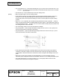
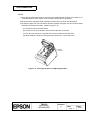
1.5 Paper Roll Supply Device
1) Supply method:
Drop-in paper roll
2) Near-end sensor:
a) Detection method:
Microswitch
b) Paper roll spool diameter: Inside: 25.4 mm {1.00"}
Outside: 31.4 mm {1.24"}
c) Near-end adjustment:
Adjusting screw
Fixed position #1 (approximately 36 mm {1.42"})
#2 (approximately 41 mm {1.61"})
(The adjusting screw has two positions.)
NOTES: • A command can be used to select whether printing is stopped or not when the paper
near end is detected.
• When the paper roll diameter becomes sufficiently small, the sensor detects a
near-end of the paper roll, and the PAPER OUT LED indicator lights. If the sensor
is enabled by ESC c 4, the printer stops printing.
After installing a new paper roll, close the roll paper cover; then the printer restarts
printing.
3) Paper width selection:
80 mm {3.15"} (default setting)
By adjusting the paper roll spacer, it is also possible to set optional
positions in the range of 38 to 70 mm {1.50 to 2.76"}. The range of 71
to 79 mm {2.80 to 3.11"} cannot be set.
NOTES: • Be sure to set the paper width with the memory switch to adjust printing to the print
width.
• Never change the paper width from narrow to wide once you set the paper width to
narrow.
Example: 60 mm {2.36"} → 80 mm {3.15"}
The reason not to change the width setting if the printer has ever been used is
because once narrow paper is used, some part of the head always contacts the
platen. Therefore, if a width setting of 80 mm is set, there is a possibility that the
head or the cutter blade may be worn out. By this means, printing is inhibited in the
area described above.
• If roll paper other than the specified ones is used, the paper near-end may not be
detected correctly. However, the paper near-end for roll paper that has a 12 mm
{0.47"} inside diameter and 18 mm {0.71"} outside diameter or 12 mm inside
diameter and 22 mm {0.87"} outside diameter can be detected, even though it is not
as accurate as the specified roll paper.
TITLE
EPSON
TM-L90
Specification
(STANDARD)
SHEET
REVISION
E
NO.
NEXT
SHEET
7
6
Confidential
1.6 Paper Specifications
1) Paper type:
Specified thermal paper
The following four kinds of paper can be used:
• Receipt paper, continuous label paper (without black mark)
• Receipt paper (with black mark)
• Die-cut label paper (without black mark)
• Die-cut label paper (with black mark)
Refer to Function 49 of the GS ( E command for the paper layout details.
NOTES: • Die-cut label paper is a label paper that has a predefined size of labels with an
interval between labels.
• Continuous label paper is a label roll paper without labels die-cut in predefined
sizes and label length is variable with an autocutter.
• Continuous label paper can be used with the same settings as for receipt paper
(without black mark).
• When a die-cut label (with black mark) is printed, the user must consider the print
position and the autocutting position. If printing is executed on the backing paper
(liner) or the label on backing paper is cut by the autocutter, the thermal print head
may be damaged.
• Die-cut labels (with black marks) cannot be used in the automatic paper layout
setting mode.
2) Form:
Paper roll
3) Paper width:
80 mm paper width model: 79.5 ± 0.5 mm {3.13 ± 0.02"}
60 mm paper width model: 59.5 ± 0.5 mm {2.34 ± 0.02"}
38 mm paper width model: 37.5 ± 0.5 mm {1.48 ± 0.02"}
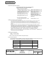
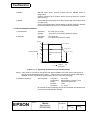
4) Paper roll size:
Roll diameter:
Take-up paper roll width:
TITLE
EPSON
TM-L90
Specification
(STANDARD)
Maximum 90 mm {3.54"}
80, 60, 38, +0.5/-1.0 mm
{3.15", 2.36", 1.50", +0.02"/-0.04"}
SHEET
REVISION
E
NO.
NEXT
SHEET
8
7
Confidential
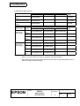
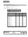
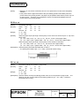
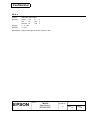
5) Specified roll paper type No.
Receipt
Single-color thermal roll
paper
Single-color thermal roll
paper (thickness type)
Two-color thermal roll
paper
Die-cut label
(face stock)
Single-color
label (face
stock) paper
Two-color
label (face
stock) paper
Paper width
60 mm {2.36"}
80 mm {3.15"}
Length
of label
25 mm
{1"}
51 mm
{2"}
76 mm
{3"}
102mm
{4"}
25 mm
{1"}
51 mm
{2"}
76 mm
{3"}
102mm
{4"}
38 mm {1.50"}
Original
paper
ENTPD080090
---
---
TF60KS-E
ENTPE080090
---
---
TF11KS-ET
ENTPC080090
---
---
PD750R
80 mm {3.15"}
Liner width
60 mm {2.36"}
38 mm {1.50"}
ENTLA080090025
ENTLA060090025
ENTLA038090025
ENTLA080090051
ENTLA060090051
---
ENTLA080090076
ENTLA060090076
---
ENTLA080090102
ENTLA060090102
---
ENTLB080090025
ENTLB060090025
ENTLB038090025
ENTLB080090051
ENTLB060090051
---
ENTLB080090076
ENTLB060090076
---
ENTLB080090102
ENTLB060090102
---
Original
paper
NOTES: • To ensure print quality, be sure to use the specified paper.
• Refer to 7) of this section for notes on using two-color thermal paper.
• Print quality may be reduced if labels (face stock) are used for high ratio printing, such as
full dot or outline character printing.
TITLE
EPSON
TM-L90
Specification
(STANDARD)
SHEET
REVISION
E
NO.
NEXT
SHEET
9
8
Confidential
6) Specified original paper type No.:
The following original paper can be used for receipt:
(Paper marked with * is a specified roll paper.)
• Single-color thermal roll paper:
*TF60KS-E (paper thickness: 75 µm)
*TF11KS-ET (paper thickness: 145 µm)
TF50KS-E (paper thickness: 65 µm)
PD160R (paper thickness: 75 µm)
P350 (paper thickness: 62 µm)
F5041 (paper thickness: 60 µm)
KF50 (paper thickness: 62 µm)
• Two-color thermal roll paper:
*PD750R (paper thickness: 75 µm)
Nippon Paper Industries Co., Ltd.
Nippon Paper Industries Co., Ltd.
Nippon Paper Industries Co., Ltd.
Oji Paper Mfg. Co., Ltd.
Kanzaki Specialty Paper (USA)
Mitsubishi HiTec Paper
Flensburg GmbH (Germany)
KANZAN Spezialpapiere GmbH
(Germany)
Oji Paper Mfg. Co., Ltd.
7) Notes on using two-color thermal paper
• Two-color printing is performed using a two-color thermal paper, if the two-color print is
selected by the customized value setting with Function 5 of the GS ( E command.
• There may be some cases where the print color may not be clear depending on the print
pattern.
• Printing with Color 2 (red on the specified two-color thermal paper) may fade over time,
depending on the environmental circumstances. To keep the print for long-term storage, it is
recommended to print with Color 1 (black on the specified two-color thermal paper).
• The reliability when two-color thermal paper is used differs from the reliability when
single-color thermal paper is used. Refer to Section 1.12, Reliability, for details.
• Make sure to use the specified two-color thermal paper in two-color printing.
thermal print head may be damaged.
Otherwise, the
8) Paper roll spool diameter
Inside:
25.4 mm {1.00"}
Outside: 31.4 mm {1.24"}
NOTE: Paper must not be pasted to the paper roll spool.
9) Print density adjustment
For best print quality and reliability, select the proper print density for the paper type used. See
the table below. Print density can be set with a software command.
Roll Paper No.
ENTPC series
ENTPD series
ENTPE series
ENTLA series
ENTLB series
Original Paper No.
P350
KF50
TF60KS-E, TF50KS-E, PD750R,
F5041
PD160R, TF11KS-ET
TITLE
EPSON
TM-L90
Specification
(STANDARD)
SHEET
REVISION
E
Density Level
90 %
95 %
100 %
105 %
130 %
NO.
NEXT
SHEET
10
9
Confidential
10) Paper to use for high speed
If any one of the following types of thermal paper is used, the customized value setting can be
used to set the maximum print speed to 150 mm/s {5.91"/s} (level 9):
• ENTLA series
• TF60KS-E
• PD160R
• TF50KS-E
• P350
• F5041
• KF50
11) Requirement for die-cut label length
(when die-cut labels (without black marks) or die-cut labels (with black marks) are used)
30.4–106.6
25.4–101.6
[Units: mm]
Figure 1.6.1
Requirement for Die-cut Label Length
12) Requirement for black mark intervals (when receipt paper (with black marks) is used)
Back (non-printing face)
Preprintable area
15
or
more
40 – 300
Paper feeding
direction
[Units: mm]
Figure 1.6.2
Requirement for Black Mark Intervals
TITLE
EPSON
TM-L90
Specification
(STANDARD)
SHEET
REVISION
E
NO.
NEXT
SHEET
11
10
Confidential
13) Requirement for black mark position (when die-cut labels (with black marks) are used)
Back (non-printing face)
4
Paper feeding
direction
5
15 or more
d
e
c
Figure 1.6.3
[Units: mm]
Requirement for Black Mark Position
NOTES: • If die-cut labels (with black marks) are used, set the paper layout using Function 49 of
the GS ( E command.
• The allowable relation between the reflecting rate in the black mark portion (c) and the
non black mark portion (d and e) must be as shown in the table below (d is the back of
label and liner, e is a back of liner):
Allowable combination of the reflecting rate [Units: %]
Black mark portion c
17
16
15
14
13
or less
Non black mark portion d, e
90
85
80
75
70
or more
• The reflecting rate means the value which is measured with a Macbeth density meter
(PCMII) D filter.
TITLE
EPSON
TM-L90
Specification
(STANDARD)
SHEET
REVISION
E
NO.
NEXT
SHEET
12
11
Confidential
1.7 Printable Area
1) Paper roll
Example:
<80 mm paper width model>
<70 mm paper width model>
79.5 ± 0.5 mm
69.5 ± 0.5 mm
0.125 mm
0.125 mm
576 dot
512 dot
4.85 mm
2.65 mm
72 mm (dot #1 ~ #576)
2.65 mm
64 mm (dot #1 ~ #512)
<60 mm paper width model>
<58 mm paper width model>
59.5 ± 0.5 mm
57.5 ± 0.5 mm
0.125 mm
2.85 mm
0.125 mm
432 dot
416 dot
2.85 mm
2.65 mm
54 mm (dot #1 ~ #432)
Figure 1.7.1
2.65 mm
52 mm (dot #1 ~ #416)
2.85 mm
Printable Area (for Thermal Paper)
NOTES: • The printable area may be out of alignment by 2 mm {0.08"} maximum (left or right), due
to the paper position or tolerance of parts. Therefore, the print area must be set in the
range of more than 2 mm from the edges of the paper. To make the margin for both
sides safely, it is recommended to set a margin of 2.6 mm {0.1"} or more, as shown in
Figure 1.7.1.
• A roll paper which has a 71 to 79 mm of the paper width cannot be used because of the
thickness of the paper roll spacer.
Table 1.7.1
Paper Width and Printable Area
Paper width (mm)
(80)
(70)
(65)
(60)
(58)
(50)
(45)
(38)
Printable area (mm)
72
64
59
54
52
44
39
32
Left margin (mm)
2.65
2.65
2.65
2.65
2.65
2.65
2.65
2.65
Right margin (mm)
4.85
2.85
2.85
2.85
2.85
2.85
2.85
2.85
Positioning dot
number
1∼576
1∼512
1∼472
1∼432
1∼416
1∼352
1∼312
1∼256
Total number of dots
576
512
472
432
416
352
312
256
(Numeric values used here are average values for designing. Only the paper width dimension is
exact. The values in parentheses are the maximum value for the paper tolerance.)
TITLE
EPSON
TM-L90
Specification
(STANDARD)
SHEET
REVISION
E
NO.
NEXT
SHEET
13
12
Confidential
2) Die-cut Labels (face stocks)
Make a margin of 2.8 mm {0.11"} or more from the label edges on both left and right sides as the
printable area of the label (face stock).
Liner width
Label (face stock) width
1.5 or more
Printable area
2.8 or more
2.8 or more
1.5 or more
[Units: mm]
Figure 1.7.2
Printable Area (for Labels)
NOTES: • If the margins are not set, the printing may be off the label due to paper misalignment or
the parts tolerance.
• A label which has a 71 to 79 mm of the liner width cannot be used because of the
thickness of the paper roll spacer.
Table 1.7.2
Example of Liner Width and Printable Area
Liner width (mm)
(80)
(70)
(60)
(50)
(45)
(38)
Label (face stock)
width (mm)
76
66
56
46
41
34
Printable area (mm)
70
60
50
40
35
28
Left margin (mm)
2.9
2.9
2.9
2.9
2.9
2.9
Right margin (mm)
3.1
3.1
3.1
3.1
3.1
3.1
Positioning dot
number
17 ∼ 576
17 ∼ 496
17 ∼ 416
17 ∼ 336
17 ∼ 296
17 ∼ 240
Total number of dots
560
480
400
320
280
224
(The label must be positioned in the center of the liner. Numeric values used here are center values in
designing. Only paper width is for nominal dimension. The values in parenthesis are the maximum
value for the paper tolerance.)
TITLE
EPSON
TM-L90
Specification
(STANDARD)
SHEET
REVISION
E
NO.
NEXT
SHEET
14
13
Confidential
1.8 Printing and Cutting Positions
Approx. 29
Manual-cutter position
26.3
14.8
Approx. 14
Auto-cutter
Autocutter blade
blade position
position
Paper feed direction
Center of the print dotline
[ Units: mm (All the numeric
values
are typical.) ]
[Units:
mm]
Figure 1.8.1
Printing and Cutting Positions
NOTE: Numeric values used here are typical values; the values may vary slightly as a result of paper
slack or variations in the paper. Take this into account when setting the cutting position of the
autocutter.
1.9 Internal Buffer
1) Receive buffer:
Selectable as 45 bytes or 4KB using a memory switch
2) User-defined buffer:
Downloaded bit image:
User-defined characters:
3) Macro buffer:
Approximately 12KB
(common for all models)
Approximately 11KB
(for ANK/Multilingual model)
Approximately 15KB
(for Japanese model)
2KB
4) NV (non-volatile) graphics data area:
0 bytes through 384KB
5) NV user memory:
1KB through 192KB
6) Page mode area:
106KB
NOTE: Since the NV graphics data area and the NV user memory use the same memory area, each
area has a limitation. Refer to GS ( E <Function 5> for details.
TITLE
EPSON
TM-L90
Specification
(STANDARD)
SHEET
REVISION
E
NO.
NEXT
SHEET
15
14
Confidential
1.10 Electrical Characteristics
+24 VDC ± 7% (optional power supply:
1) Supply voltage:
EPSON PS-170, PS-180)
2) Current consumption (at 24 V at room temperature):
Mean: Approximately 1.7 A (for single-color printing)
(Character font A, alphanumeric, capital letters, 36-character
rolling pattern, full-column printing)
Mean: Approximately 1.7 A (for two-color printing)
(Character font A, alphanumeric, capital letters, 36-character
rolling pattern, full-column printing, changing the print color each
line)
Peak: Approximately 7.7 A maximum (with full dot printing)
Standby:
Mean: Approximately 0.1 A
NOTE: Maximum 1 A for drawer kick-out driving.
1.11 EMI and Safety Standards Applied
EMC is measured using SEIKO EPSON’s AC adapter PS-170 or PS-180
1) Europe
CE marking:
Directive: 89/336/EEC
EN55022 Class B
EN55024
IEC61000-4-2
IEC61000-4-3
IEC61000-4-4
IEC61000-4-5
IEC61000-4-6
IEC61000-4-11
Safety Standard: EN 60950
2) North America
EMI: FCC/ICES-003 Class A
Safety standards: UL1950/CSA C22.2 No.950
3) Japan
EMC: VCCI Class A, JEIDA-52
4) Oceania
EMC: AS/NZS 3548
UL’s Conditions of Acceptability
1. This component has been judged on the basis of the required spacings in the Standard for Safety
of Information Technology Equipment, Including Electrical Business Equipment, CAN/CSA C22.2
No.950-95 * UL 1950, Third Edition, including revisions through revision date March 1, 1998, which
are based on the Fourth Amendment to IEC 950, Second Edition, which would cover the
component itself if submitted for Listing.
2. The equipment has been evaluated for use in a Pollution Degree 2 environment.
TITLE
EPSON
TM-L90
Specification
(STANDARD)
SHEET
REVISION
E
NO.
NEXT
SHEET
16
15
Confidential
1.12 Reliability
1) Life:
Printer mechanism (including the thermal head life)
When printing labels (face stock) with the ENTLA series (in single-color mode):
1,000,000 labels issued
(When the length of the label in the paper feeding direction is 25.4 mm
{1"} through 63.5 mm {2.5"}. The value above corresponds to
approximately 30 km to 70 km {18.64 to 43.5 miles} of running length.
When printing labels whose length exceeds 63.5 mm, the label-issuing
life is 70 km {43.5 miles} of running length.)
When issuing receipts (thickness type) with the ENTPE series (in single-color mode):
10,000,000 lines printed (3.75 mm {0.15"} for one line)
(When the value above is calculated, the printer uses 15-line feeding
and 10-line printing repeatedly with a 145 µm paper thickness. The
value above corresponds to approximately 60 km {37.28 miles} of
running length.)
When printing receipts with the ENTPD series (in single-color mode):
20,000,000 lines printed (3.75 mm {0.15"} for one line)
(When the value above is calculated, the printer uses 15-line feeding
and 10-line printing repeatedly with 75 µm of paper thickness. The
value above corresponds to approximately 120 km {74.57 miles} of
running length.)
When printing labels (face stock) with the ENTLB series (in two-color mode):
500,000 labels issued
(When the length of the label in the paper feed direction is 25.4 mm
{1"} through 63.5 mm {2.5"}. The value above corresponds to
approximately 15 km to 35 km {9.32 to 21.75 miles} of running length.)
When printing receipts with the ENTPC series (in two-color mode):
10,000,000 lines printed (3.75 mm {0.15"} for one line)
(When the value above is calculated, the printer uses 15-line feeding
and 10-line printing repeatedly. The value above corresponds to
approximately 60 km {37.28 miles} of running length.)
Thermal head:
150 million pulses
Autocutter:
When cutting receipts: 2,000,000 cuts (except for KF50, when the paper thickness is less than
75 µm)
1,200,000 cuts (for KF50 (KANZAN))
1,000,000 cuts (when the paper thickness is more than 75 µm and less
than 145 µm)
When cutting labels: 1,000,000 cuts (when the backing paper (liner) between labels is cut)
500,000 cuts (when the continuous label paper is cut. 1,000,000 cuts if
the cutter blade is cleaned)
NOTE: If a die-cut label is used, cut the backing paper (liner) between labels (face stock).
Otherwise, adhesive attaches the cutter blade, and it may cause cutting trouble.
End of life is defined as the point at which the component reaches the beginning of the
wearout period.
TITLE
EPSON
TM-L90
Specification
(STANDARD)
SHEET
REVISION
E
NO.
NEXT
SHEET
17
16
Confidential
2) MTBF:
360,000 hours (when printing receipts with the ENTPD series in
single-color)
(Failure is defined as a random failure occurring during the random
failure period.)
3) MCBF:
70,000,000 lines printed (when printing receipts with the ENTPD series
in single-color)
(This is an average failure interval based on failures relating to wearout
and random failures up to the life of 20,000,000 lines printed.)
1.13 Environmental Conditions
1) Temperature:
Operating:
Storage:
5 to 45°C {41 to 113°F}
-10 to 50°C {14 to 122°F} (except for paper)
2) Humidity:
Operating:
Storage:
10 to 90% RH
10 to 90% RH (except for paper)
[% RH]
90
34 ˚C, 90 %
80
40 ˚C, 65 %
60
Relative humidity
45 ˚C, 50 %
Operating environment
range
40
20
10
0
Figure 1.13.1
0
10
20
30
40
50
[˚C]
Ambient
temperature
Operating Temperature and Humidity Range
NOTE: If the printer is not used for a long time with paper installed, some part of the printing may be
light, due to the deformation of the paper. If the printer is not used for a long time with paper
installed, be sure to feed paper approximately 30 mm {1.18"} before printing.
3) Vibration resistance:
When packed:
Frequency:
Acceleration:
Sweep:
Duration:
Directions:
5 to 55 Hz
2
Approximately 19.6 m/s {2 G}
10 minutes (half cycle)
1 hour
x, y, and z
No external or internal damage should be found after the vibration test,
and the unit should operate normally.
TITLE
EPSON
TM-L90
Specification
(STANDARD)
SHEET
REVISION
E
NO.
NEXT
SHEET
18
17
Confidential
4) Impact resistance:
When packed:
Package:
Height:
Directions:
EPSON standard package
60 cm {23.62"}
1 corner, 3 edges, and 6 surfaces
No external or internal damage should be found after the drop test, and
the unit should operate normally.
When unpacked: Height:
Directions:
5 cm {1.97"}
Lift one edge and release it
(for all 4 edges).
When the printer is not printing, no external or internal damage should
be found after the drop test.
5) Acoustic noise (operating):
Approximately 53 dB (ANSI bystander position)
NOTE: The value as shown above is measured when the EPSON evaluation printing pattern is
used. This value may be different, depending on the paper to be printed, the print duty, or
the print conditions, such as the print speed or the print density.
1.14 Installation
The TM-L90 series printer can be installed horizontally or vertically.
When installing the printer horizontally using an autocutter with a full cut, attach the paper exit guide
packed in the printer’s box to the printer, and change the location of the paper roll near-end sensor
(refer to Appendix C).
(Vibration during paper cutting and using a drawer should be considered.
the printer from moving. Affixing tapes are provided as an option.)
An optional hanging bracket can attach the printer to a wall.
user’s manual to install the wall mount.)
TITLE
EPSON
TM-L90
Specification
(STANDARD)
Take measures to prevent
(Follow the procedure described in the
SHEET
REVISION
E
NO.
NEXT
SHEET
19
18
Confidential
2. CONFIGURATION
2.1 Interface
2.1.1 RS-232 Serial Interface
2.1.1.1 Specifications
Data transmission:
Serial
Synchronization:
Asynchronous
Handshaking:
DTR/DSR or XON/XOFF control
Signal levels:
MARK = -3 to -15 V:
SPACE = +3 to +15 V:
Baud rates:
2400, 4800, 9600, 19200, 38400, 57600, 115200 bps
(bps: bits per second)
Data word lengths:
7 or 8 bits
Parity settings:
None, even, odd
Stop bits:
1 bit or more
Connector (printer side):
Female DSUB-25 pin connector
Logic "1"/ OFF
Logic "0"/ ON
NOTES: • The handshaking, data word length, baud rate, and parity depend on the DIP switch
settings. (Refer to Section 3.3.3.) or the memory switch. (Refer to the GS ( E
command.)
• The stop bit from the printer side is fixed to 1.
2.1.1.2 Switching between online and offline
The printer does not have an online/offline switch.
The printer goes offline:
1) Between when the power is turned on (or the printer is reset using the interface) and when the
printer is ready to receive data.
2) During the self-test.
3) When the cover is open.
4) During paper feeding using the paper FEED button.
5) When the printer stops printing due to a paper-end (in cases when an empty paper supply is
detected by either paper roll end detector or the paper roll near-end detector with a printing halt
feature due to a paper-end enabled by ESC c 4).
6) During standby status for macro execution.
7) When a temporary abnormality occurs in the power supply voltage.
8) When an error has occurred.
TITLE
EPSON
TM-L90
Specification
(STANDARD)
SHEET
REVISION
E
NO.
NEXT
SHEET
20
19
Confidential
2.1.1.3 Interface connector terminal assignments and signal functions
The interface connector terminal assignments and signal functions are described in Table 2.1.1.
Table 2.1.1
Pin
number
Signal name
Signal
direction
FG
TXD
RXD
RTS
DSR
—
Output
Input
Output
Input
7
20
SG
DTR
—
Output
Function
Frame ground
Transmit data
Receive data
Same as DTR signal (pin 20)
This signal indicates whether the host computer can receive data.
SPACE indicates that the host computer can receive data, and MARK
indicates that the host computer cannot receive data.
When DTR/DSR control is selected, the printer transmits data after
confirming this signal.
When XON/XOFF control is selected, the printer does not check this
signal.
Changing memory switch Msw 1-7 enables this signal to be used as a
reset signal for the printer (refer to Section 3.3.4).
The printer is reset when the signal remains MARK for 1 ms or more
(refer to Section 2.1.1.6).
Signal ground
1) When DTR/DSR control is selected, this signal indicates whether
the printer is busy. SPACE indicates that the printer is ready to
receive data, and MARK indicates that the printer is busy. The busy
condition can be changed by using memory switch as follows (refer to
Section 3.3.4):
Memory switch
Printer status
Msw 1-3 status
BUSY
1. During the period from when the power is BUSY
turned on (including resetting using the
interface) to when the printer is ready to
receive data.
2. During the self-test.
BUSY
BUSY
3. When the cover is open.
—
BUSY
4. During paper feeding using the paper
—
BUSY
FEED button.
5. When the printer stops printing due to a
—
BUSY
paper-end.
6. During standby status for macro
—
BUSY
execution.
7. When a temporary abnormality occurs in
—
BUSY
the power supply voltage.
8. When an error has occurred.
—
BUSY
9. When the receive buffer becomes full.
BUSY
BUSY
(*1)
Offline
1
2
3
4
6
TM-L90 Printer Status and Signals
TITLE
EPSON
TM-L90
Specification
(STANDARD)
SHEET
REVISION
E
NO.
NEXT
SHEET
21
20
Confidential
Table 2.1.1
Pin
number
25
Signal name
INIT
Signal
direction
Input
TM-L90 Printer Status and Signals (Continued)
Function
2) When XON/XOFF control is selected:
The signal indicates whether the printer is correctly connected
and is ready to receive data. SPACE indicates that the printer is
ready to receive data. The signal is always SPACE except in the
following cases:
• During the period from when the power is turned on to when the
printer is ready to receive data
• During the self-test
Changing memory switch Msw 1-8 enables this signal to be used as
a reset signal for the printer.
The printer is reset when the signal remains SPACE for 1 ms or
more.
*1: • When the receive buffer capacity is specified to 45 bytes:
When the remaining space in the receive buffer drops to 16 bytes, the printer status becomes
“buffer full” and it remains “buffer full” until the space in the receive buffer increases to 26
bytes.
• When the receive buffer capacity is specified as 4KB:
When the remaining space in the receive buffer drops to 128 bytes, the printer status becomes
“buffer full” and it remains “buffer full” until the space in the receive buffer increases to 256
bytes.
• The printer ignores the data received when the remaining space in the receive buffer is 0 bytes.
TITLE
EPSON
TM-L90
Specification
(STANDARD)
SHEET
REVISION
E
NO.
NEXT
SHEET
22
21
Confidential
2.1.1.4 XON/XOFF transmission timing
When XON/XOFF control is selected, the printer transmits XON or XOFF signals as follows.
Transmission timing differs depending on the memory switch setting.
Table 2.1.2
XON transmission
XOFF transmission
XON/XOFF Transmission Timing
Memory switch
Msw 1-3 status
Printer status
ON
OFF
➀ When the printer goes online after turning on the power Transmit Transmit
(or resetting using interface)
➁ When the receive buffer is released from the buffer
Transmit Transmit
full state
➂ When the printer switches from offline to online
—
Transmit
➃ When the printer recovers from an error using the
—
Transmit
DLE ENQ 1 or DLE ENQ 2 commands
➄ When the receive buffer becomes full
Transmit Transmit
➅ When the printer switches from online to offline
—
Transmit
NOTES: • The XON code is <11>H and the XOFF code is <13>H.
• In case ➂, XON is not transmitted when the receive buffer is full.
• In case ➅, XOFF is not transmitted when the receive buffer is full.
• When memory switch Msw 1-3 is set to OFF, XON is not transmitted if the printer is in
offline state in case ➁.
2.1.1.5 Notes on setting the handshake operation using memory switch Msw 1-3
1) The printer mechanism stops but does not become busy when: an error has occurred, the cover is
open, printing stops due to a paper-end, or paper is fed using the paper FEED button.
2) When setting the memory switch to enable handshaking with the printer, be sure to check the printer
status using the GS a command and the ASB function. In this setting, the default value of n for GS
a is 2. The printer automatically transmits the printer status, depending on online/offline changes.
3) When using DLE EOT, DLE ENQ, and DLE DC4 be sure that the receive buffer does not become
full.
• When using a host that cannot transmit data when the printer is busy:
If an error has occurred, DLE EOT, DLE ENQ, and DLE DC4 cannot be used when the printer is
busy due to a receive buffer-full state.
• When using a host that can transmit data when the printer is busy:
When the receive buffer becomes full while transmitting bit-image data, and DLE EOT, DLE
ENQ, or DLE DC4 is used while sending bit-image data, the code is processed as bit-image
data. The data transmitted when the receive buffer is full may be lost.
Example: Check the printer status using GS r after transmitting each line of data and use the
4KB receive buffer. Transmit data one line at a time so that the receive buffer
does not become full.
TITLE
EPSON
TM-L90
Specification
(STANDARD)
SHEET
REVISION
E
NO.
NEXT
SHEET
23
22
Confidential
2.1.1.6 Notes on resetting the printer using the interface
The printer can be reset using interface pins 6 and 25 by changing the memory switch setting.
Signal Line
Pin 6 (DSR)
Table 2.1.3 Reset Switching
Memory Switch Reset Condition
Msw 1-7: ON
MARK level input
Pin 25 (INIT)
Msw 1-8: ON
SPACE or TTL-HIGH level input
To reset the printer, the following requirements must be satisfied.
• DC characteristics:
Table 2.1.4
Reset DC Characteristics
Pin 6 (DSR)
Pin 25 (INIT)
-15 to -3 V
+2 to +15 V
Reset active voltage
VA
Reset negative voltage
VN
+3 to +15 V
-15 to + 0.8 V
Reset active current
IA
-5.3 mA (maximum)
1 mA (maximum)
Reset negative current
IN
-5.0 mA (maximum)
-2 mA (maximum)
Input impedance
RIN
3 kΩ (minimum)
TITLE
EPSON
TM-L90
Specification
(STANDARD)
SHEET
REVISION
E
NO.
NEXT
SHEET
24
23
Confidential
• AC characteristics:
Minimum reset pulse width:
TRS
1 ms (minimum)
• When using pin 6 (DSR) (Msw 1-7: ON):
TRS
TRS
H
SPACE
L
MARK
Figure 2.1.1
Minimum Reset Pulse Width (Pin 6)
• When using pin 25 (INIT) (Msw 1-8: ON):
TRS
TRS
H
SPACE (H)
MARK (L) L
Figure 2.1.2
Minimum Reset Pulse Width (Pin 25)
NOTES: • When a signal that does not satisfy the requirements above is input, printer operation is
not guaranteed. When a signal is input to pin 25 (INIT) at the TTL level, the
requirements above must also be satisfied. Although a signal is input to pin 6 (DSR) at
the TTL level, according to the DC characteristics described above, the operation is not
guaranteed and pin 6 cannot be controlled.
• When pin 6 (DSR) and pin 25 (INIT) are open, the printer is operating.
TITLE
EPSON
TM-L90
Specification
(STANDARD)
SHEET
REVISION
E
NO.
NEXT
SHEET
25
24
Confidential
2.1.2 IEEE 1284 Bidirectional Parallel Interface (Parallel Interface Specifications)
Copyright © 1994 by the Institute of Electrical and Electronic Engineers, Inc.
2.1.2.1 Compatibility mode
(data transmission from host to printer: Centronics compatible)
1) Outline
Compatibility mode supports the compatibility with a Centronics parallel interface.
2) Specifications
Data transmission:
8-bit parallel
Synchronization:
Externally supplied nStrobe signals
Handshaking:
nAck and Busy signals
Signal levels:
TTL compatible
Connector:
ADS-B36BLFDR176 (Honda) or equivalent (IEEE 1284 Type B)
3) Switching between online and offline
The printer is not equipped with any online/offline switch.
in the following conditions:
The printer is placed into offline status
1) When the power is turned on or until the printer becomes ready for data transmission after it
is initialized by the reset signal (nInit) from the interface.
2) During the self-test.
3) When the cover is open.
4) During paper feeding using the paper FEED button.
5) When the printer stops printing due to a paper-end (in cases when an empty paper supply is
detected by either the paper roll end detector or the paper roll near-end detector with a
printing halt feature due to a paper end enabled by ESC c 4).
6) During standby status for macro execution.
7) When a temporary abnormality occurs in the power supply voltage.
8) When an error has occurred.
2.1.2.2 Reverse mode (data transmission from printer to host)
The STATUS data transmission from the printer to the host proceeds in the Nibble or Byte mode.
• Description
This mode allows data transmission from the asynchronous printer under the control of the host.
Data transmissions in the Nibble Mode are made via the existing control lines in units of four bits
(a nibble). In the Byte Mode, data transmissions are accomplished by making the eight-bit data
lines bidirectional.
Both modes cannot work at the same time as the Compatibility Mode, thereby causing half duplex
transmission.
TITLE
EPSON
TM-L90
Specification
(STANDARD)
SHEET
REVISION
E
NO.
NEXT
SHEET
26
25
Confidential
2.1.2.3 Interface Pin Assignments for Each Mode
Pin Source
Compatibility Mode
Nibble Mode
1
Host
nStrobe
HostClk
2
Host/Ptr
Data0 (LSB)
Data0 (LSB)
3
Host/Ptr
Data1
Data1
4
Host/Ptr
Data2
Data2
5
Host/Ptr
Data3
Data3
6
Host/Ptr
Data4
Data4
7
Host/Ptr
Data5
Data5
8
Host/Ptr
Data6
Data6
9
Host/Ptr
Data7 (MSB)
Data7 (MSB)
10 Printer
nAck
PtrClk
11 Printer
Busy
PtrBusy/Data3, 7
12 Printer
PError
AckDataReq/Data2, 6
13 Printer
Select
Xflag/Data1, 5
14 Host
nAutoFd
HostBusy
15
NC
ND
16
GND
GND
17
FG
FG
18 Printer
Logic-H
Logic-H
19
GND
GND
20
GND
GND
21
GND
GND
22
GND
GND
23
GND
GND
24
GND
GND
25
GND
GND
26
GND
GND
27
GND
GND
28
GND
GND
29
GND
GND
30
GND
GND
31 Host
nInit
nInit
32 Printer
nFault
nDataAvail/Data0, 4
33
GND
ND
34 Printer
DK_STATUS
ND
35 Printer
+5V
ND
36 Host
nSelectIn
1284-Active
*NC: Not Connected
ND: Not Defined
TITLE
EPSON
TM-L90
Specification
(STANDARD)
SHEET
REVISION
E
Byte Mode
HostClk
Data0 (LSB)
Data1
Data2
Data3
Data4
Data5
Data6
Data7 (MSB)
PtrClk
PtrBusy
AckDataReq
Xflag
HostBusy
ND
GND
FG
Logic-H
GND
GND
GND
GND
GND
GND
GND
GND
GND
GND
GND
GND
nInit
nDataAvail
ND
ND
ND
1284-Active
NO.
NEXT
SHEET
27
26
Confidential
NOTES: 1. A prefix “n” to signal names refers to “L” active signals. If the host does not support the
signal lines listed above, both-way communication fails.
2. For interfacing, signal lines shall use twisted pair cables with the return sides connected
to signal ground level.
3. Interfacing conditions shall be all based on the TTL level to meet the characteristics
described below. In addition, both rise time and fall time of each signal shall be
0.5 µs or less.
4. Data transmission shall not ignore the signal nAck or Busy. An attempt to transmit data
with either signal, nAck or Busy, ignored can cause lost data
5. Interface cables shall be as short in length as possible.
2.1.2.4 Electrical Characteristics
DC Characteristics (Except Logic-H, +5 V signals)
Specifications
Characteristics
Symbol
Conditions
Min
Max
Output HIGH voltage
VOH
*2.4 V
5.5 V
*IOH=0.32 mA
Output LOW voltage
VOL
-0.5 V
*0.4 V
*IOL=-12 mA
Output HIGH current
IOH
0.32 mA
-
VOH=2.4 V
Output LOW current
IOL
-12 mA
-
VOL=0.4 V
Input HIGH voltage
VIH
2.0 V
-
Input LOW voltage
VIL
-
Input HIGH current
IIH
-
-0.32 mA
VIH=2.0 V
Input LOW current
IIL
-
12 mA
VIL=0.8 V
0.8 V
Logic-H Signal Sender Characteristics
Specifications
Characteristics
Symbol
Min
Max
3.0 V
5.5 V
Output HIGH voltage
VOH
Output LOW voltage
VOL
-
TITLE
EPSON
TM-L90
Specification
(STANDARD)
2.0 V
Conditions
While the power is OFF
SHEET
REVISION
E
NO.
NEXT
SHEET
28
27
Confidential
Characteristics
Output HIGH voltage
+5 V Signal Sender Characteristics
Specifications
Symbol
Min
Max
VOH
*2.4 V
5.5 V
Conditions
*IOH=0.32 mA
Output LOW voltage
VOL
-
- **
While the power is OFF
Output HIGH current
IOH
-
0.32 mA
VOH=2.4 V
Output LOW current
IOL
- **
-
While the power is OFF
** No guarantee is offered to VOL and IOL while the power is OFF.
2.1.2.5 Data Receiving Timing (Compatibility Mode)
DATA
Data n
Data n+1
nStrobe
tSetup
tSTB
Busy
tHold
Peripheral Busy
tReady
tBUSY
nAck
tReply
tACK
tnBUSY
tNext
Data Hold Time (host)
tHold
Specifications
Min [ns] Max [ns]
750
--
Data Setup Time
tSetup
750
--
STROBE Pulse Width
tSTB
750
--
READY Cycle Idle Time
tReady
0
--
BUSY Output Delay Time
tBUSY
0
500
Data Processing Time
tReply
0
∞
ACKNLG Pulse Width
tACK
500
10 µs
BUSY Release Time
tnBUSY
0
∞
ACK Cycle Idle Time
tNext
0
--
Characteristics
Symbol
*The printer latches data at a nStrobe ↓ timing
TITLE
EPSON
TM-L90
Specification
(STANDARD)
SHEET
REVISION
E
NO.
NEXT
SHEET
29
28
Confidential
2.1.2.6 Notes on resetting the printer through the interface
To enable the printer reset through the interface nInit signal (pin #31) in compatibility mode, the
following signal timing shall be statisfied. However, the printer reset is ignored when the signal
nSelectln (pin #36, 1284-Active HIGH) is active in reverse mode.
• DC characteristics:
TTL level
• AC characteristics:
Minimum reset pulse width:
Trailing edge period:
Leading edge period:
TRS
tf
tr
50 µs (min.)
500 ns (max.)
500 ns (max.)
nSelectIn
(1284-Active)
min.1 ms
min.0
nInit
tf
tr
TRS
TITLE
EPSON
TM-L90
Specification
(STANDARD)
SHEET
REVISION
E
NO.
NEXT
SHEET
30
29
Confidential
2.1.2.7 Reception of status from the printer through the bidirectional parallel interface
In the bidirectional parallel interface specifications, the printer status transmission is available by using
the both-way communication facility in the Nibble/Byte Modes in accordance with the IEEE 1284.
In this case, unlike the RS-232 serial interface specifications, the real-time interruptions from the printer
to the host are disabled and thus precautions must be taken:
1) The allowable capacity of the printer internal buffer is 99 bytes (except ASB status). Status
signals exceeding this capacity will be discarded. To prevent possible loss of status, the host
shall be ready for data reception (Reverse Mode).
2) When ASB is used, the host is preferably in the wait state for data reception (Reverse Idle Mode).
When this state is not available, the host shall enter the Reverse Mode to continually monitor the
presence of data.
3) When ASB is used, preference shall be given to the ASB status for transmission over the other
status signals.
TITLE
EPSON
TM-L90
Specification
(STANDARD)
SHEET
REVISION
E
NO.
NEXT
SHEET
31
30
Confidential
2.1.2.8 Notes on setting memory switch Msw 1-3 to ON
1) The printer mechanism stops but does not become busy when: an error has occurred, the cover is
open, printing stops due to a paper-end, or paper is fed using the paper FEED button.
2) When setting the memory switch to enable handshaking with the printer, be sure to check the printer
status using the GS a command and the ASB function. In this setting, the default value of n for GS
a is 2. The printer automatically transmits the printer status, depending on online/offline changes.
3) When using DLE EOT, DLE ENQ, and DLE DC4, be sure that the receive buffer does not become
full.
• When the printer is busy due to a receive buffer-full state:
If an error has occurred, DLE EOT, DLE ENQ, and DLE DC4 cannot be used.
2.1.3 Other Interfaces
Various interface boards (EPSON UB series, except UB-P02 and UB-U05) can be used.
TITLE
EPSON
TM-L90
Specification
(STANDARD)
SHEET
REVISION
E
NO.
NEXT
SHEET
32
31
Confidential
2.2 Connectors
2.2.1 Interface Connectors
Refer to Section 2.1, Interfaces.
2.2.2 Power Supply Connector
This connector is used to connect the printer to an external power source.
1) Pin assignments:
Refer to Table 2.2.1.
Table 2.2.1 Power Supply Connector Pin Assignments
Pin Number
Signal Name
1
+24 V
2
GND
3
NC
SHELL
Frame GND
SHELL
Figure 2.2.1
Power Supply Connector
NOTE: Be sure to ground the metal of the interface using through hole for the frame ground.
2) Connector model:
Printer side:
User side:
Hosiden TCS7960-532010 or equivalent
Hosiden TCP8927-631100 or equivalent
Hosiden TCP8927-531100 or equivalent
TITLE
EPSON
TM-L90
Specification
(STANDARD)
SHEET
REVISION
E
NO.
NEXT
SHEET
33
32
Confidential
2.2.3 Drawer Kick-out Connector (Modular Connector)
The pulse specified by ESC p or DLE DC4 is output to this connector.
of the input signal by using the DLE EOT, GS a, or GS r commands.
1) Pin assignments:
The host can confirm the status
Refer to Table 2.2.2
Table 2.2.2 Drawer Kick-out Connector Pin Assignments
Pin Number
Signal Name
Direction
1
Frame GND
—
2
Drawer kick-out drive signal 1
Output
3
Drawer open/close signal
Input
4
+24 V
—
5
Drawer kick-out drive signal 2
Output
6
Signal GND
—
+24 V is output through pin 4 when the power is turned on.
the drawer.
1
Figure 2.2.2
2) Connector model:
However, pin 4 must be used only for
6
Drawer Kick-out Connector
Printer side:
User side:
DDK 285D-7660J-100 or equivalent
6-position 6-contact (RJ12 telephone jack)
3) Drawer kick-out drive signal
Output signal:
CAUTION:
Output voltage: Approximately 24 V
Output current: 1 A or less
To avoid an overcurrent, the resistance of the drawer kick-out solenoid must be 24 Ω or
more.
Output waveforms:
Outputs the waveforms in Figure 2.2.3 to the points A and B in Figure
2.2.4.
ON time and OFF time are specified by ESC p or DLE DC4.
ON2time
t 1x
msec
Figure 2.2.3
Drawer Kick-out Drive Signal Output Waveform
TITLE
EPSON
OFF
time
t 1x
2 msec
TM-L90
Specification
(STANDARD)
SHEET
REVISION
E
NO.
NEXT
SHEET
34
33
Confidential
4) Drawer open/close signal
Input signal level (connector pin 3):
"L" = 0 to 0.8 V
"H" = 2 to 5 V
Drawer kick-out connector
1
F. G
With shielded
Drawer kick-out solenoid
2
A
3
P-GND
+24V
4
5
B
Drawer open/close switch
6
P-GND
Printer side
User side (Drawer kick-out side)
Figure 2.2.4
Drawer Circuitry
NOTES: 1. Use a shielded cable for the drawer connector cable.
2. Two driver transistors cannot be energized simultaneously.
3. The drawer drive duty must be as shown below.
ON time
≤ 0.2
(ON time + OFF time)
4. Be sure to use the printer power supply (connector pin 4) for the drawer power source.
5. The resistance of the drawer kick-out solenoid must not be less than the specified
resistance. Otherwise, an overcurrent could damage the solenoid.
6. Do not connect telecommunication network to the drawer kick-out connector.
TITLE
EPSON
TM-L90
Specification
(STANDARD)
SHEET
REVISION
E
NO.
NEXT
SHEET
35
34
Confidential
3. FUNCTIONS
3.1 List of Commands
Command
Name
HT
Horizontal tab
LF
Print and line feed
FF
Print and return to standard mode (in page mode)
CR
Print and carriage return
CAN
Cancel print data in page mode
DLE EOT
Real-time status transmission
DLE ENQ
Real-time request to printer
DLE DC4
Generate pulse in real-time
Execute power-off sequence
Clear buffer(s)
ESC FF
Print data in page mode
ESC SP
Set right-side character spacing
ESC !
Select print mode(s)
ESC $
Set absolute print position
ESC %
Select/cancel user-defined character set
ESC &
Define user-defined characters
ESC ∗
Select bit-image mode
ESC -
Turn underline mode on/off
ESC 2
Select default line spacing
ESC 3
Set line spacing
ESC =
Select peripheral device
ESC ?
Cancel user-defined characters
ESC @
Initialize printer
ESC D
Set horizontal tab positions
ESC E
Turn emphasized mode on/off
ESC G
Turn double-strike mode on/off
ESC J
Print and feed paper
ESC L
Select page mode
ESC M
Select character font
ESC R
Select an international character set
ESC S
Select standard mode
ESC T
Select print direction in page mode
ESC V
Turn 90° clockwise rotation mode on/off
ESC W
Set printing area in page mode
TITLE
EPSON
TM-L90
Specification
(STANDARD)
SHEET
REVISION
E
NO.
NEXT
SHEET
36
35
Confidential
Command
Name
ESC \
Set relative print position
ESC a
Select justification
ESC c 3
Select paper sensor(s) to output paper-end signals
ESC c 4
Select paper sensor(s) to stop printing
ESC c 5
Enable/disable panel buttons
ESC d
Print and feed n lines
ESC p
Generate pulse
ESC t
Select character code table
ESC {
Turn upside-down printing mode on/off
FS ( L
Select label and black mark control function(s)
GS 8 L
Set graphics data
GS ( L
GS ( C
Edit of user NV memory
GS ( D
Enable / disable real-time command
GS ( E
User setup commands
GS ( H
Request response transmission
GS ( K
Select print control method(s)
GS ( M
Customize printer control value(s)
GS ( N
Select character style(s)
GS ( k
Setup and print symbol
GS !
Select character size
GS $
Set absolute vertical print position in page mode
GS ∗
Define downloaded bit image
GS ( A
Execute test print
GS /
Print downloaded bit image
GS :
Start/end macro definition
GS B
Turn white/black reverse printing mode on/off
GS C 0
Select counter print mode
GS C 1
Select count mode (A)
GS C 2
Set counter
GS C ;
Select count mode (B)
GS H
Select printing position of HRI characters
GS T
Set print position to the beginning of print line
GS g 0
Initialize maintenance counter
GS g 2
Transmit maintenance counter
GS I
Transmit printer ID
TITLE
EPSON
TM-L90
Specification
(STANDARD)
SHEET
REVISION
E
NO.
NEXT
SHEET
37
36
Confidential
Command
Name
GS L
Set left margin
GS P
Set horizontal and vertical motion units
GS V
Select cut mode and cut paper
GS W
Set printing area width
GS \
Set relative vertical print position in page mode
GS ^
Execute macro
GS a
Enable/disable Automatic Status Back (ASB)
GS b
Turn smoothing mode on/off
GS c
Print counter
GS f
Select font for HRI characters
GS h
Set bar code height
GS k
Print bar code
GS r
Transmit status
GS w
Set bar code width
Kanji command list
(when the Japanese, Simplified Chinese, Traditional Chinese, or Korean model is used)
Command
Name
FS !
Set print mode(s) for Kanji characters
FS &
Select Kanji character mode
FS ( A (*)
Select Kanji character style(s)
FS –
Turn underline mode on/off for Kanji characters
FS .
Cancel Kanji character mode
FS 2
Define user-defined Kanji characters
FS C
Select Kanji character code system
FS S
Set Kanji character spacing
FS W
Turn quadruple-size mode on/off for Kanji characters
(*) FS ( A is effective only in the Japanese model.
®
The commands listed below in the first column are defined as “obsolete commands” in the ESC/POS
command system. This printer supports both upward-compatible commands and obsolete
commands. However, the upward-compatible commands are recommended for use.
Obsolete command
GS v 0
Print raster bit image
Upward-compatible command
GS ( L <Function 112 + 50>
NOTE: “Obsolete commands” are commands that are supported by legacy models; however it is
recommended to replace them with upward-compatible commands, because they will not be
supported in the future products.
TITLE
EPSON
TM-L90
Specification
(STANDARD)
SHEET
REVISION
E
NO.
NEXT
SHEET
38
37
Confidential
3.2 Character Code Tables
FS
CAN
DC4
3.2.1 Page 0 (PC437: USA, Standard Europe) (International Character Set: USA)
NOTE: The character code tables show only character configurations.
print pattern.
TITLE
EPSON
TM-L90
Specification
(STANDARD)
They do not show the actual
SHEET
REVISION
E
NO.
NEXT
SHEET
39
38
Confidential
3.2.2 Page 1 (Katakana)
TITLE
EPSON
TM-L90
Specification
(STANDARD)
SHEET
REVISION
E
NO.
NEXT
SHEET
40
39
Confidential
3.2.3 Page 2 (PC850: Multilingual)
TITLE
EPSON
TM-L90
Specification
(STANDARD)
SHEET
REVISION
E
NO.
NEXT
SHEET
41
40
Confidential
3.2.4 Page 3 (PC860: Portuguese)
TITLE
EPSON
TM-L90
Specification
(STANDARD)
SHEET
REVISION
E
NO.
NEXT
SHEET
42
41
Confidential
3.2.5 Page 4 (PC863: Canadian-French)
TITLE
EPSON
TM-L90
Specification
(STANDARD)
SHEET
REVISION
E
NO.
NEXT
SHEET
43
42
Confidential
3.2.6 Page 5 (PC865: Nordic)
TITLE
EPSON
TM-L90
Specification
(STANDARD)
SHEET
REVISION
E
NO.
NEXT
SHEET
44
43
Confidential
3.2.7 Page 16 (WPC1252)
••
TITLE
EPSON
TM-L90
Specification
(STANDARD)
SHEET
REVISION
E
NO.
NEXT
SHEET
45
44
Confidential
3.2.8 Page 17 (PC866: Cyrillic #2)
TITLE
EPSON
TM-L90
Specification
(STANDARD)
SHEET
REVISION
E
NO.
NEXT
SHEET
46
45
Confidential
3.2.9 Page 18 (PC852: Latin2)
SP
TITLE
EPSON
TM-L90
Specification
(STANDARD)
SHEET
REVISION
E
NO.
NEXT
SHEET
47
46
Confidential
3.2.10 Page 19 (PC858)
TITLE
EPSON
TM-L90
Specification
(STANDARD)
SHEET
REVISION
E
NO.
NEXT
SHEET
48
47
Confidential
3.2.11 Page 20 (Thai character code 42)
TITLE
EPSON
TM-L90
Specification
(STANDARD)
SHEET
REVISION
E
NO.
NEXT
SHEET
49
48
Confidential
3.2.12 Page 21 (Thai character code 11)
TITLE
EPSON
TM-L90
Specification
(STANDARD)
SHEET
REVISION
E
NO.
NEXT
SHEET
50
49
Confidential
3.2.13 Page 22 (Thai character code 13)
TITLE
EPSON
TM-L90
Specification
(STANDARD)
SHEET
REVISION
E
NO.
NEXT
SHEET
51
50
Confidential
3.2.14 Page 23 (Thai character code 14)
TITLE
EPSON
TM-L90
Specification
(STANDARD)
SHEET
REVISION
E
NO.
NEXT
SHEET
52
51
Confidential
3.2.15 Page 24 (Thai character code 16)
TITLE
EPSON
TM-L90
Specification
(STANDARD)
SHEET
REVISION
E
NO.
NEXT
SHEET
53
52
Confidential
3.2.16 Page 25 (Thai character code 17)
TITLE
EPSON
TM-L90
Specification
(STANDARD)
SHEET
REVISION
E
NO.
NEXT
SHEET
54
53
Confidential
3.2.17 Page 26 (Thai character code 18)
TITLE
EPSON
TM-L90
Specification
(STANDARD)
SHEET
REVISION
E
NO.
NEXT
SHEET
55
54
Confidential
3.2.18 Page 255 (Space Page)
TITLE
EPSON
TM-L90
Specification
(STANDARD)
SHEET
REVISION
E
NO.
NEXT
SHEET
56
55
Confidential
3.2.19 International Character Sets
ASCII code (Hex)
Country
23
24
40
5B
5C
5D
5E
60
7B
7C
7D
7E
USA
#
$
@
[
\
]
^
`
{
|
}
~
France
#
$
à
°
ç
§
^
`
é
ù
è
¨
Germany
#
$
§
Ä
Ö
Ü
^
`
ä
ö
ü
ß
U.K.
£
$
@
[
\
]
^
`
{
|
}
~
Denmark I
#
$
@
Æ
Ø
Å
^
`
æ
ø
å
~
Sweden
#
¤
É
Ä
Ö
Å
Ü
é
ä
ö
å
ü
Italy
#
$
@
°
\
é
^
ù
à
ò
è
ì
Spain I
Pt
$
@
¡
Ñ
¿
^
`
¨
ñ
}
~
Japan
#
$
@
[
¥
]
^
`
{
|
}
~
Norway
#
¤
É
Æ
Ø
Å
Ü
é
æ
ø
å
ü
Denmark II
#
$
É
Æ
Ø
Å
Ü
é
æ
ø
å
ü
Spain II
#
$
á
¡
Ñ
¿
é
`
í
ñ
ó
ú
Latin America
#
$
á
¡
Ñ
¿
é
ü
í
ñ
ó
ú
Korea
#
$
@
[
W
]
^
`
{
|
}
~
TITLE
EPSON
TM-L90
Specification
(STANDARD)
SHEET
REVISION
E
NO.
NEXT
SHEET
57
56
Confidential
3.3 Switches and Buttons
3.3.1 Power Button (Non-locking push button)
1) The power button located on the upper right front of the printer turns the power on or off.
power button is enabled or disabled with a DIP switch.
The
NOTE: Turn on the power only after connecting the power supply.
2) To turn the power off, press the power button for at least 3 seconds.
3) The printer operates depending on the DIP switch setting (enable/disable power button function)
as shown in Table 3.3.1.
Table 3.3.1
When the power button is
pressed for at least 3 seconds
When the power off is
controlled by the host PC
(Transmission of DLE DC4 2)
Printer Operation by DIP SW1-1
Setting of the DIP SW 1-1
On (power button is disabled)
Off (power button is enabled)
The printer is reset
The printer power is turned off.
(only when an error has
occurred). (*1)
The printer flashes the
The printer power is turned off.
POWER LED after power off
processing. (*2)
NOTES: *1: Refer to Section 3.8.1 for types of error.
*2: Refer to Section 3.4.1 for the POWER LED flashing pattern.
<How to disable the power button>
1) Power button cover
A power button cover option is available.
accidentally.
Use this cover to avoid turning power off
2) DLE DC4 (Execute power-off sequence)
To control the printer’s power off in situations when the power button is covered, disable the
power button using the DIP switch and the power off command DLE DC4. (Refer to
Appendix G for details.)
NOTE: Pulling the paper out forcibly causes turning the power button on when the power
button is turned off, if +24 V power voltage is supplied and the DIP switch 1-1 is off
(the power button is effective).
3.3.2 Panel Buttons
1) FEED button:
Non-locking push button
[Function] • If you push this button once and release it, the printer feeds paper one line, based on
the line spacing set by ESC 2 and ESC 3. However, paper feeding using the FEED
button cannot be performed under the following conditions:
① The paper roll end sensor detects a paper end.
② When the roll paper cover is open.
• If you push this button when the printer is in the macro execution standby state, the
defined macro is executed.
• During self-test printing, you can stop the self-test temporarily by pressing this button
and restart it by pressing the button again.
NOTE: This button is disabled by ESC c 5.
TITLE
EPSON
TM-L90
Specification
(STANDARD)
SHEET
REVISION
E
NO.
NEXT
SHEET
58
57
Confidential
3.3.3 DIP Switches
DIP switch 1 is located on the left side inside the roll paper cover and is accessible when the DIP switch
cover is removed. DIP switch 2 is located on the main PCB.
3.3.3.1 Serial interface
Table 3.3.2
SW 1
DIP Switch 1
ON
Function
OFF
1
Power button function
Disabled
Enabled
2
Interface condition selection
By DIP switch
By memory switch
3
Handshaking
XON/XOFF control
DTR/DSR control
4
Word length
7 bits
8 bits
5
Parity check
Yes
No
6
Parity selection
Even
Odd
Transmission speed selection
Refer to Table 3.3.3
7
8
Table 3.3.3 Transmission Speed
Transmission Speed (bps)
SW1-7
SW1-8
2400
ON
ON
4800
OFF
ON
9600
ON
OFF
19200
OFF
OFF
bps: bits per second
NOTE: Changes in DIP switch settings are recognized only when the printer power is turned on or
when the printer is reset by using the interface.
Table 3.3.4
SW 2
1
DIP Switch 2
ON
Function
Reserved
--
TITLE
EPSON
OFF
TM-L90
Specification
(STANDARD)
Fixed to Off.
SHEET
REVISION
E
NO.
NEXT
SHEET
59
58
Confidential
3.3.3.2 Parallel interface
Table 3.3.5
SW 1
DIP Switch 1
ON
Function
OFF
1
Operation of the power button
Disabled
Enabled
2
Reserved
Fixed to On
--
3–8
Reserved
--
Fixed to Off
NOTE: Changes in DIP switch settings are recognized only when the printer power is turned on or
when the printer is reset by using the interface.
Table 3.3.6
SW 2
1
DIP Switch 2
ON
Function
Reserved
OFF
--
Fixed to Off
3.3.4 Memory Switches
The memory switches are: Msw 1, Msw 2, Msw 8.
These switches
• Set customized values
• Set the communication conditions of the serial interface
1) Tables for memory switches Msw 1, Msw 2, Msw 8 are shown below.
Table 3.3.7 Memory Switch Msw 1
Function
48 (Off)
Transmit the power ON information
Does not transmit
49 (On)
Transmits
2
Capacity of receive buffer
4KB
45 bytes
3
Conditions for BUSY
Receive buffer full
or offline
Receive buffer full
4
Data processing for receiving error
Prints "?"
Ignored
5
Automatic line feed
Disabled
Enabled
6
Reserved
Fixed to Off
--
7
Pin #6: Selection of reset signal
Not used
Used
8
Pin #25: Selection of reset signal
Not used
Used
Bit
1
TITLE
EPSON
TM-L90
Specification
(STANDARD)
SHEET
REVISION
E
NO.
NEXT
SHEET
60
59
Confidential
Table 3.3.8
Function
Memory Switch Msw 2
48 (Off)
49 (On)
Fixed to On (Do not change the setting)
Bit
1
Reserved
2
Autocutter operation
Disabled
Enabled
3
Reserved
--
--
4
Reserved
--
--
5
Reserved
--
--
6
Reserved
--
--
7
Reserved
--
--
8
Reserved
--
--
Bit
1
Table 3.3.9
Function
Reserved
Memory Switch Msw 8
48 (Off)
--
49 (On)
--
Method to recover from the paper
2
layout error
(*1)
DLE ENQ, DLE DC4 (fn
= 8) or the cover
open/close. (*2)
DLE ENQ, DLE DC4 (fn
= 8)
3 PAPER LED coming on when an
(*1) near-end detected.
Comes on
Does not come on
4
Selection of the maximum length of
automatic paper measurement
160 mm
300 mm
5
Enable left or right margin of bar code
print
Does not enable margin
Enables margin
6
Feeding paper to the print starting
position at power on
Enabled
Disabled
7
Reserved
--
--
8
Printer cover open during operation
Errors that automatically
recover
Errors that can possibly
recover
NOTES: *1: Supported only by the firmware version 1.05 or later (for Japanese, multilingual character
model) or 1.06 or later (for ANK model).
*2: When the printer recovers from the paper layout error if Msw 8-2 is off, the automatic
paper measurement is done. If the settings for the paper layout are already stored in
the NV memory, these settings are overwritten with the result of the automatic paper
recognition.
TITLE
EPSON
TM-L90
Specification
(STANDARD)
SHEET
REVISION
E
NO.
NEXT
SHEET
61
60
Confidential
2) Customized value
The customized value is set with the GS ( E command.
Function
Selection of the NV user memory
capacity
Selection of the NV graphics
memory capacity
Value
64KB
1KB
128KB
192KB
None
64KB
128KB
192KB
256KB
320KB
384KB
--
Selection of the paper width
38 mm, 39 mm, ….. 79 mm, 80 mm
(43 settings in increments of 1 mm)
Selection of the print control
One-part energizing
Two-part energizing
Three-part energizing
Four-part energizing
70 %
75 %
80 %
85 %
90 %
95 %
100 %
105 %
110 %
115 %
120 %
125 %
130 %
135 %
Selection of the paper
Single-color
Two colors
Selection of the print speed
Print speed level 1 (max. 26 mm/s), print speed level 2,
print speed level 3, print speed level 4,
print speed level 5, print speed level 6 (max. 120 mm/s),
print speed level 7, print speed level 8,
print speed level 9 (max. 150 mm/s).
Selection of black-color density in
two-color printing
Light
Medium
Dark
--
Selection of the print density
140 %
NOTES: • Since the NV graphics data area and the NV user memory use the same memory area,
each area has a limitation. Refer to GS ( E <Function 5> for details.
• The maximum print speed is available only in one-part energizing mode.
• Four-part energizing mode can reduce power consumption.
• The print width can be set for 43 paper types with a 1 mm pitch in the range from 38 to
80 mm {1.50 to 3.15"}. However, print width cannot be set in the range from 71 to 79
mm {2.80 to 3.11"}, because of the thickness of the paper roll spacer.
TITLE
EPSON
TM-L90
Specification
(STANDARD)
SHEET
REVISION
E
NO.
NEXT
SHEET
62
61
Confidential
3) Communication conditions of the serial interface
The communication conditions of the serial interface are set with the GS ( E command.
Function
Baud rate
Value
4800 bps
2400 bps
9600 bps
19200 bps
38400 bps
57600 bps
115200 bps
--
None
Odd
Even
--
Handshaking
DSR/DTR control
XON/XOFF control
Data length
7 bits
8 bits
Parity
NOTE: To set the communication conditions with the memory switch, turn DIP SW 1-2 off in
advance.
TITLE
EPSON
TM-L90
Specification
(STANDARD)
SHEET
REVISION
E
NO.
NEXT
SHEET
63
62
Confidential
3.4 Indicators
3.4.1 Panel LEDs
1) Power (POWER) LED:
Green
On:
Power is stable.
Off:
Power is not stable.
Flashing: During execution of each operation
<Flashing pattern>
During executing each operation: Flashing
Approximately 320 ms
Power off termination (after executing DLE DC4 2): Flashing
2) Paper roll end (PAPER OUT) LED:
Red
On:
The roll paper near end or real end is detected.
Off:
Paper is loaded (normal condition)
Blinking: • Self-test waiting state for test print
• Macro execution standby state when the macro execution command is used.
Table 3.4.1 Standby State Indication
State
PAPER LED Flashing Pattern
PAPER OUT
Waiting for self-test printing
to be continued or macro
Approximately 320 ms
execution ready state.
Recovery Conditions
Pressing the FEED button
causes self-test printing to be
continued or executes the
macro.
NOTE: A macro can be executed r times (r specifies the number of times to execute the macro)
within the specified definition range. The macro can be executed continuously or can be
executed by pressing the button. If the macro is executed by pressing the FEED button, the
PAPER OUT LED flashes to indicate the macro execution ready state. (See Section 6,
Commands.)
TITLE
EPSON
TM-L90
Specification
(STANDARD)
SHEET
REVISION
E
NO.
NEXT
SHEET
64
63
Confidential
3) Error (ERROR) LED:
Red
On:
Offline (except during paper feeding using the FEED button and during test printing,
and in the error state). Refer to “Switching between online and offline” in Section 2.1,
Interfaces.
Flashing:
Error (refer to Section 3.8)
Off:
Normal condition
Figure 3.4.1
Panel Switches and Indicators
TITLE
EPSON
TM-L90
Specification
(STANDARD)
SHEET
REVISION
E
NO.
NEXT
SHEET
65
64
Confidential
3.5 Self-test
1) The printer has a self-test function that checks the following:
• Control circuit functions
• Printer mechanisms
• Print quality
• Control software version
• DIP switch settings
• Memory switch settings
• Paper width to be set
2) Executing the self-test
[Starting the self-test]
To start the self-test on roll paper, hold down the paper FEED button and turn on the printer with
the cover closed, and continue holding down the paper FEED button until the ERROR LED comes
on; then the current printer status (*1) is printed.
(*1) • Control software version
• DIP switch settings
• Memory switch settings
(The contents of the memory switch settings may not be the same as the actual print in
the self-test. If the paper layout is not saved in memory, the printer prints “6553.5.”)
[Self-test standby state]
After printing the current printer status, the printer prints the message "If you want to continue
SELF-TEST printing, please press FEED button." The PAPER OUT LED indicator flashes and
the printer enters the test printing (*2) standby state. Press the paper FEED button to start test
printing.
(*2) • Prints with a rolling pattern using only the built-in character set
• Autocuts after completing the rolling pattern printing
• Feeds to the print starting position
3) Ending the self-test
After a number of lines are printed, the printer indicates the end of the self-test by printing
"∗∗∗ completed ∗∗∗," and initializes.
TITLE
EPSON
TM-L90
Specification
(STANDARD)
SHEET
REVISION
E
NO.
NEXT
SHEET
66
65
Confidential
3.6 Hexadecimal Dumping
1) Hexadecimal dumping function
This function prints the data transmitted from the host computer in hexadecimal numbers and their
corresponding characters.
2) Starting hexadecimal dumping
Open the cover and turn the power on while pressing the paper FEED button (located inside the
printer). Then close the cover or execute the GS ( A command. The printer first prints
"Hexadecimal Dump
To terminate..." on the paper roll and prints the received print data in
hexadecimal numbers and their corresponding characters.
NOTES: 1. If a character does not correspond to the data received, the printer prints "."
2. During hexadecimal dumping, any commands other than DLE EOT, DLE ENQ, and
DLE DC4 do not function.
3. Insufficient print data to fill the last line can be printed by setting the printer offline.
3) Ending hexadecimal dumping
Hexadecimal dumping ends by turning the power off, pressing the paper FEED button three times,
or resetting the printer after printing has finished.
<Printing example>
Hexadecimal Dump
To terminate hexadecimal dump,
press FEED button three times.
1B 21 00 1B 26 02 40 40 1B 69
1B 25 01 1B 63 34 00 1B 30 31
41 42 43 44 45 46 47 48 49 4A
. ! . . & . @@ . i
.%. . c 4 . . 01
A BCD E FGH I J
*** completed ***
TITLE
EPSON
TM-L90
Specification
(STANDARD)
SHEET
REVISION
E
NO.
NEXT
SHEET
67
66
Confidential
3.7 Memory Switch Setting Mode
1) Memory switch setting function
The following memory switch can be set by operating the button and opening and closing the cover:
➀ Enabling or disabling the autocutter
➁ Setting communication conditions of the serial interface
➂ Making settings related to the serial communication
•
Capacity of the receive buffer
•
Data processing for receiving error
•
Conditions for BUSY
➃ Selection of interface reset signal
➄ Setting paper width
➅ Setting print density
➆ Setting type of paper (single-color/two-color)
➇ Setting label
2) Starting the memory switch setting mode
Open the roll paper cover and turn the power on while holding down the paper FEED button (located
inside the printer), and continue holding down the paper FEED button until the ERROR LED comes on;
release the paper FEED button once the ERROR LED comes on. Next, press the paper FEED button
(located inside the printer) twice, and close the cover. Then, the printer prints the possible setting
contents of the memory switch and instructions. Follow the instructions to set the memory switches.
3) Ending the memory switch setting mode
Once setting is performed, the setting contents are stored; then the printer executes initialization.
initializing, the printer enters the normal state.
Paper FEED button
(inside the printer)
TITLE
EPSON
TM-L90
Specification
(STANDARD)
SHEET
REVISION
E
NO.
NEXT
SHEET
68
67
After
Confidential
3.8 Automatic Paper Recognition Function
1) Automatic paper recognition function
This function is to detect the paper type – any of the following papers – and store that information
in the volatile memory (RAM).
➀ Die-cut label (face stock) paper (without black mark)
➁ Receipt, continuous roll paper label (without black mark)
➂ Receipt, continuous roll paper label (with black mark)
In this function, the length of the label interval in ➀ (distance between the bottom of the label and
the bottom of the next label) and the length of the black mark (BM) interval in ➂ (distance between
the top of the BM and the top of the next BM) are also measured.
2) Starting the automatic paper recognition function
This function will start in the following case, and the paper is fed until it is finished:
• When the power is turned on and the paper is loaded, and then the roll paper cover is closed.
• When the power is turned on if the paper is already loaded.
NOTES: • If die-cut labels (with black marks) are used, the automatic paper recognition function
must not be used. Use Function 49 or the GS ( E command.
•
If the automatic paper layout setting mode for die-cut labels (with black marks) is used,
the automatic paper recognition function may not work. In this case, the paper layout
is set as a receipt (without black marks).
•
If the paper layout information is already written in the NV memory, this function will not
work. For the paper layout setting in the NV memory, refer to function 49 of GS ( E,
GS ( A, or Section 3.9, Automatic paper layout setting mode.
3.9 Automatic Paper Layout Setting Mode
1) Automatic paper layout setting mode
This function is to measure the paper layout settings of the paper inserted automatically and store
them in the NV memory.
2) Starting the automatic paper layout setting mode
Open the roll paper cover and turn the power on while holding down the paper FEED button
(located inside the printer), and continue holding down the paper FEED button until the ERROR
LED comes on; release the paper FEED button once the ERROR LED comes on. Press the
paper FEED button (located inside the printer) six times, and then close the roll paper cover.
NOTES: • If die-cut labels (with black marks) are used, the automatic paper recognition function
must not be used. Use Function 49 or the GS ( E command.
•
If the automatic paper layout setting mode for die-cut labels (with black marks) is used,
the automatic paper recognition function may not work. In this case, the paper layout
is set as a receipt (without black marks).
3) Ending the automatic paper layout setting mode
Once the setting is performed, the automatic paper layout setting mode is ended.
TITLE
EPSON
TM-L90
Specification
(STANDARD)
SHEET
REVISION
E
NO.
NEXT
SHEET
69
68
Confidential
3.10 Paper Setting Clear Mode for Paper Layout (*1)
1) Paper setting clear function for paper layout
This function changes all setting values for the paper layout to “nothing set”.
2) Starting the Mode
Open the roll paper cover and turn the power on while holding down the paper FEED button
(located inside the printer), and continue holding down the paper FEED button until the ERROR
LED comes on; release the paper FEED button once the ERROR LED comes on. Next, press the
paper FEED button (located inside the printer) four times, and close the cover. Then the printer
clears the paper layout setting.
NOTE:
*1: Supported only by the firmware version 1.05 or later (for Japanese, multilingual character
model) or 1.06 or later (for ANK model).
3.11 Error Processing
3.11.1 Error Types
1) Errors that recover automatically
Table 3.11.1
Automatically Recoverable Errors
ERROR LED Flashing Pattern
Error
Description
Paper roll cover
open error (when
recoverable error
is selected) (*1)
Printing on the
paper roll is not
performed correctly
due to a
cover-open.
The temperature of
the print head is
extremely high.
Print head high
temperature error
(*2)
Recovery
Approximately 320 ms
Recovers automatically
when the roll paper cover
is closed.
Recovers automatically
when the print head cools.
NOTES: *1: The roll paper cover open error operation can be selected with a memory switch.
*2: This is an error when the print head temperature becomes high because of the
continuous high duty printing, and is not abnormal. If a unexpected value is detected by
the abnormal cause in the circuit, the internal circuit connection error comes out.
TITLE
EPSON
TM-L90
Specification
(STANDARD)
SHEET
REVISION
E
NO.
NEXT
SHEET
70
69
Confidential
2) Errors that can be recovered with a command
Table 3.11.2
Errors That Can Possibly Recover
ERROR LED Flashing Pattern
Error
Description
Paper roll cover
open error
(when an error that
can possibly
recover is selected)
Autocutter error (*2)
Printing on the
paper roll is not
performed
correctly due to a
cover-open.
The autocutter
does not work
correctly.
Recovers by DLE ENQ 1,
DLE ENQ 2, or DLE DC4
(fn = 8) when the cover is
closed.
Paper layout error
(*3)
Cannot detect
the label or the
black mark.
Recovers by DLE ENQ 1,
DLE ENQ 2, or DLE DC4
(fn = 8).
Recovery
Approximately 320 ms
Recovers by DLE ENQ 1,
DLE ENQ 2, or DLE DC4
(fn = 8).
Approximately 5,120 ms
NOTES: *1: The roll paper cover open error operation can be selected with a memory switch.
*2: When an autocutter error occurs because of jammed paper, turn the power off and
remove the jammed paper; then turn the power on again.
*3: When a paper layout error occurs because of jammed paper while printing, turn the
power off and remove the jammed paper; then turn the power on again.
TITLE
EPSON
TM-L90
Specification
(STANDARD)
SHEET
REVISION
E
NO.
NEXT
SHEET
71
70
Confidential
3) Unrecoverable errors
Table 3.11.3
Error
Unrecoverable Errors
ERROR LED Flashing Pattern
Description
Recovery
Approximately 320 ms
CPU execution CPU executes an incorrect
error
address.
Impossible to
recover.
R/W error in
memory or
gate array
After R/W checking, the
printer does not work
correctly.
Impossible to
recover.
High-voltage
error
The power supply voltage is
extremely high.
Impossible to
recover.
Low-voltage
error
The power supply voltage is
extremely low.
Impossible to
recover.
Internal circuit
connection
error
UIB error
Internal circuits are not
connected correctly.
Impossible to
recover.
An abnormal operation
occurs in UIB.
Impossible to
recover.
Approximately 5,120 ms
NOTE: When any error shown above occurs, turn off the power as soon as possible.
3.11.2 Printer Operation When an Error Occurs
The printer executes the following operations when detecting an error.
• Stops all printer operations (printing, feeding, autocutting, or drawer driving).
• Goes BUSY (When the BUSY in offline is set for the conditions for BUSY with the memory switch)
• Flashes the ERROR LED.
3.11.3 Data Receive Error (Only for the Serial Interface Model)
If one of the following errors occurs during serial interface communication, the printer prints "?" or
ignores the data, depending on the setting of the memory switch.
• Parity error
• Framing error
• Overrun error
TITLE
EPSON
TM-L90
Specification
(STANDARD)
SHEET
REVISION
E
NO.
NEXT
SHEET
72
71
Confidential
3.12 Cover Open Button
When the cover open button is pressed, the roll paper cover is opened.
NOTES: • Be sure to use the cover open button to open the roll paper cover.
• Do not open the roll paper cover during printing.
• Do not operate the cover open button during the autocutting operation; otherwise the
mechanism may be damaged.
3.13 Cover Open Sensor
The cover open sensor monitors the roll paper cover. When the sensor detects a cover open during
printing, the printer enters an error state and goes offline automatically. The printer recovers to online
when the roll paper cover is closed.
When an error that automatically recovers is selected:
To return to online, close the roll paper cover.
If the printer detects the cover open during printing, the error LED flashes. When the roll paper cover
is closed, the error LED turns off and the printer initializes by itself and starts printing from the beginning
of the line that stopped printing.
When an error that can possibly recover is selected:
When the cover is closed, the printer recovers by DLE ENQ 1 or DLE ENQ 2. If the roll paper cover is
open during standby, the printer goes offline. When the roll paper cover is closed, the printer recovers
to online.
NOTE: Whether the cover is open or not does not affect the status reported by the paper roll sensor.
3.14 Print Buffer-full Printing
• In standard mode
When subsequent data is received after the printer processes one line of data in the print buffer, the
printer prints the processed line and automatically feeds the paper one line.
• In paper mode
When subsequent data is received after the printer processes one line of data in the print buffer, the
printer prints the processed line and automatically sets the print starting position to the next line.
TITLE
EPSON
TM-L90
Specification
(STANDARD)
SHEET
REVISION
E
NO.
NEXT
SHEET
73
72
Confidential
4. CASE SPECIFICATIONS
4.1 External Dimensions and Mass
Height:
203 mm {7.99"}
Width:
140 mm {5.51"}
Depth:
148 mm {5.83”}
Mass:
Approximately 1.9 kg {4.18 lb}
(except for the paper roll)
4.2 Color
EPSON standard color (ECW, EDG)
4.3 External Appearance
[Units: mm]
Figure 4.3.1
External Appearance
TITLE
EPSON
TM-L90
Specification
(STANDARD)
SHEET
REVISION
E
NO.
NEXT
SHEET
74
73
Confidential
5. OPTIONS AND CONSUMABLES
5.1 Standard Accessories
• Label roll paper (diameter 40 mm {1.57"})
• User’s manual (Languages: English, German, French, Spanish, Portuguese, Italian, Dutch,
Simplified Chinese, Traditional Chinese, Japanese)
• Paper roll spacer
• Paper exit guide
• Panel label for horizontal installation
• Power switch cover
• External power supply unit (model: PS-180)
(For models packed with a power supply unit, the packed power supply differs depending on the
model.)
5.2 Options
• Affixing Velcro tape (model: DF-10)
®
• Wall handing bracket (model: WH-10)
• External power supply (model: PS-180, PS-170)
(PS-180 is a power-saving type)
• Interface boards (EPSON UB series, except UB-P02 and UB-U05)
5.3 Consumables
• Specified paper
Thermal roll paper:
Refer to Section 1.6, Paper Specifications.
TITLE
EPSON
TM-L90
Specification
(STANDARD)
SHEET
REVISION
E
NO.
NEXT
SHEET
75
74
Confidential
6. COMMANDS
6.1 Command Notation
XXXX
[Name]
The name of the command.
[Format]
The code sequence.
The numbers denoted by < >H are hexadecimal.
[ ]k indicates the contents of the [ ] should be repeated k times.
[Range]
Gives the allowable ranges, if any, for the arguments.
[Default]
Gives the default values, if any, for the command parameters.
[Description] Describes the function of the command.
[Notes]
Provides important information on setting and using the printer command, if necessary.
6.2 Explanation of Terms
1) Print buffer
The print buffer is a buffer that stores the image data to be printed.
2) Printable area
The printable area is the maximum range within which printing is possible under the printer
specifications. The printable area for this printer is as follows:
The length in the horizontal direction in standard mode:
Type of paper
Printable area
Receipt, Continuous roll paper label
72 mm {576/203"}
Die-cut label
70 mm {560/203"}
The length in the horizontal direction in page mode:
Type of paper
Receipt, Continuous roll paper label
Die-cut label
Printable area
72 mm {576/203"}
70 mm {560/203"}
The length in the vertical direction in page mode:
Type of paper
Receipt, Continuous roll paper label (single-color)
Printable area
184.5 mm {2952/406"}
Die-cut label (single-color)
101.6 mm {1624/406"}
Receipt, Continuous roll paper label (two-color)
Die-cut label (two-color)
92.25 mm {1476/406"}
TITLE
EPSON
TM-L90
Specification
(STANDARD)
SHEET
REVISION
E
NO.
NEXT
SHEET
76
75
Confidential
3) Printing area
The printing range is set by command.
The area to be printed must be ≤ the printable area.
4) Ignores the command
The state in which all codes, including parameters, are read in and discarded, and nothing
happens.
5) Inch
A unit of length.
One inch is 25.4 mm.
6) Paper layout
This is the information to control printing of labels or black mark paper. The paper layout includes
the origin of the layout, print starting position, size of label, or other information. The paper layout
is set with GS ( A and GS ( E commands for detailed control.
TITLE
EPSON
TM-L90
Specification
(STANDARD)
SHEET
REVISION
E
NO.
NEXT
SHEET
77
76
Confidential
6.3 Control Commands
HT
[Name]
Horizontal tab
[Format]
ASCII
Hex
Decimal
HT
09
9
[Description] • Moves the print position to the next horizontal tab position.
LF
[Name]
Print and line feed
[Format]
ASCII
Hex
Decimal
LF
0A
10
[Description] • In standard mode
•
Prints the data in the print buffer and feeds one line based on the current line spacing.
•
If the paper layout (the origin of the layout) specifies “bottom of the label” or “top of the black mark”
in standard mode, the printer executes either one of the following operations when the paper feed
amount exceeds the printing area in the vertical layout:
•
If the maximum height of the characters in one line exceeds the printing area specified in
the vertical layout, the printer feeds the paper to the print starting position on the next
label and executes the process of this command from the print starting position on the
next label.
•
If the maximum height of the characters in one line does not exceed the printing area
specified in the vertical layout, but the paper feed amount exceeds the printing area, the
printer executes printing on the current label and feeds the paper to the bottom of the
printing area.
• In page mode
•
Feeds one line based on the current line spacing.
FF
[Name]
Print and return to standard mode (in page mode)
[Format]
ASCII
Hex
Decimal
FF
0C
12
[Description] In page mode, prints the data in the print buffer collectively and returns to standard mode.
TITLE
EPSON
TM-L90
Specification
(STANDARD)
SHEET
REVISION
E
NO.
NEXT
SHEET
78
77
Confidential
CR
[Name]
Print and carriage return
[Format]
ASCII
Hex
Decimal
CR
0D
13
[Description] • When automatic line feed is enabled, the printer functions the same as LF.
• When automatic line feed is disabled, the printer ignores CR.
[Notes]
• The automatic line feed is ignored with a serial interface model.
• With a parallel interface model, the automatic line feed is set with memory switch 1-5 when
the printer power is turned on or reset.
CAN
[Name]
Cancel print data in page mode
[Format]
ASCII
Hex
Decimal
CAN
18
24
[Description] In page mode, deletes all the print data in the current printable area.
TITLE
EPSON
TM-L90
Specification
(STANDARD)
SHEET
REVISION
E
NO.
NEXT
SHEET
79
78
Confidential
DLE EOT n
[Name]
Transmit real-time status
[Format]
ASCII
Hex
Decimal
[Range]
1≤n≤4
DLE
10
16
EOT n
04
n
4
n
[Description] • Transmits the status specified by n in real time as follows:
n
1
Function
Transmits printer status.
2
Transmits offline status.
3
Transmits error status.
4
Transmits paper roll sensor status.
• This printer transmits the following status in real time.
•
n = 1: Printer status
Bit
Off/On
0
Off
Hex
00
Decimal
0
Function
Fixed.
1
On
02
2
Fixed.
2
Off
00
0
Drawer kick-out connector pin 3 is LOW.
On
04
4
Drawer kick-out connector pin 3 is HIGH.
3
Off
00
0
Online.
On
08
8
Offline.
4
On
10
16
Fixed.
5
Off
00
0
Not in online waiting status.
On
20
32
During online waiting status.
6
Off
00
0
Paper FEED button is turned Off.
On
40
64
Paper FEED button is turned On.
Off
00
0
Fixed.
7
NOTE: Bit 5 indicates the status for waiting for the Paper FEED button in macro
execution.
TITLE
EPSON
TM-L90
Specification
(STANDARD)
SHEET
REVISION
E
NO.
NEXT
SHEET
80
79
Confidential
•
n = 2: Offline status
Bit
Off/On
0
Off
1
On
2
Off
On
3
Off
4
5
6
7
•
n = 3: Error status
Bit
0
1
2
3
4
5
6
7
Hex
00
02
00
04
00
Decimal
0
2
0
4
0
On
On
Off
On
Off
On
Off
08
10
00
20
00
40
00
8
16
0
32
0
64
0
Off/On
Off
On
Off
On
Off
On
On
Off
On
Off
On
Off
Hex
00
02
00
04
00
08
10
00
20
00
40
00
Decimal
0
2
0
4
0
8
16
0
32
0
64
0
TITLE
EPSON
TM-L90
Specification
(STANDARD)
Function
Fixed.
Fixed.
Cover is closed.
Cover is open.
Paper is not being fed by using the paper FEED
button.
Paper is being fed by the paper FEED button.
Fixed.
No paper-end stop.
Printing is being stopped due to a paper end.
No error.
Error has occurred.
Fixed.
Function
Fixed.
Fixed.
No mechanical error.
Mechanical error has occurred.
No autocutter error.
Autocutter error occurred.
Fixed.
No unrecoverable error.
Unrecoverable error has occurred.
No automatically recoverable error.
Automatically recoverable error has occurred.
Fixed.
SHEET
REVISION
E
NO.
NEXT
SHEET
81
80
Confidential
•
[Notes]
n = 4: Continuous paper sensor status
Bit
Off/On Hex
Decimal
0
Off
00
0
1
On
02
2
2
Off
00
0
On
04
4
3
Off
00
0
On
08
8
4
On
10
16
5
Off
00
0
On
20
32
6
Off
00
0
On
40
64
7
Off
00
0
Function
Fixed.
Fixed.
Roll paper near-end sensor: paper adequate.
Roll paper near-end sensor: paper near end.
Roll paper near-end sensor: paper adequate.
Roll paper near-end sensor: paper near end.
Fixed.
Roll paper end sensor: paper present.
Roll paper end sensor: paper not present.
Roll paper end sensor: paper present.
Roll paper end sensor: paper not present.
Fixed.
• If print data includes a character string containing this command, the printer performs the
command. Users must consider this.
For example: Bit image data accidentally might include a data string with this
command.
• Do not embed this command within another command.
For example: Bit image data might include this command.
• This command is ignored when block data is transmitted.
TITLE
EPSON
TM-L90
Specification
(STANDARD)
SHEET
REVISION
E
NO.
NEXT
SHEET
82
81
Confidential
DLE ENQ n
[Name]
Real-time request to the printer
[Format]
ASCII
Hex
Decimal
[Range]
0≤n≤2
DLE
10
16
ENQ n
05
n
5
n
[Description] • Responds to a request from the host computer.
•
[Notes]
n specifies the requests as follows:
n
Request
0
Works the same as when the paper FEED button is pressed once in waiting
status during the operation of the GS ^ command.
1
Recovers from an error and restarts printing from the line where the error
occurred.
2
Recovers from an error after clearing the receive and print buffers.
• Specify n = 1 or 2 after removing the cause of the error.
• If print data includes a character string containing this command, the printer performs the
command. Users must consider this.
For example: Bit image data accidentally might include a data string with this
command.
• Do not embed this command within another command.
For example: Bit image data might include this command.
• This command is ignored when block data is transmitted.
• When the printer recovers from the paper layout error with DLE ENQ 1 or DLE ENQ 2 if Msw
8-2 is off, the automatic paper measurement is done. If the settings for the paper layout are
already stored in the NV memory, these settings are overwritten by the result of the automatic
paper recognition.
TITLE
EPSON
TM-L90
Specification
(STANDARD)
SHEET
REVISION
E
NO.
NEXT
SHEET
83
82
Confidential
DLE DC4 fn m t (fn = 1)
[Name]
Generate pulse in real-time
[Format]
ASCII
Hex
Decimal
[Range]
fn = 1
0≤m≤8
1≤t≤8
DLE
10
16
DC4
14
20
fn
1
1
m
m
m
t
t
t
[Description] Outputs the pulse specified by t in real-time to the connector pin specified by m as follows:
m
Connector pin
0
Drawer kick-out connector pin 2.
1
Drawer kick-out connector pin 5.
The pulse ON time or OFF time is set to [t × 100 ms].
• If print data includes a character string containing this command, the printer performs the
command. Users must consider this.
[Notes]
For example: A bit image accidentally might include the same data string as this
command.
• Do not embed this command within another command.
For example: Bit image data might include this command.
• This command is ignored in the following states:
•
During transmission of block data.
•
During driving of drawer kick-out.
•
When an error has occurred.
TITLE
EPSON
TM-L90
Specification
(STANDARD)
SHEET
REVISION
E
NO.
NEXT
SHEET
84
83
Confidential
DLE DC4 fn a b (fn = 2)
[Name]
Execute power-off sequence
[Format]
ASCII
Hex
Decimal
[Range]
fn = 2
a=1
b=8
DLE
10
16
DC4
14
20
fn
fn
fn
a
a
a
b
b
b
[Description] Executes the printer power-off sequence.
[Notes]
•
Stores the values of the maintenance counter.
•
Transmits the following power-off status (Header + Status + NUL).
Power off status
Hex
Decimal
Amount of data
Header
3B H
59
1 byte
Status
30 H
48
1 byte
NUL
00 H
0
1 byte
•
Executes the printer power off.
• If this command is encountered, the printer will not continue to process anything. To recover
the printer to print again, it is necessary to turn the power on again or execute a hardware
reset.
• If print data includes a character string containing this command, the printer performs the
command. Users must consider this.
For example: Bit image data accidentally might include a data string with this
command.
• Do not embed this command within another command.
For example: Bit image data might include this command.
• This command is ignored when block data is transmitted.
TITLE
EPSON
TM-L90
Specification
(STANDARD)
SHEET
REVISION
E
NO.
NEXT
SHEET
85
84
Confidential
DLE DC4 fn d1…d7 (fn = 8)
[Name]
Clear buffer(s)
[Format]
ASCII
Hex
Decimal
[Range]
fn = 8
d1 = 1, d2 = 3, d3 = 20, d4 = 1, d5 = 6, d6 = 2, d7 = 8
DLE
10
16
DC4
14
20
fn
8
8
d1…d7
d1…d7
d1…d7
[Description] • Clears all data stored in the receive buffer and the print buffer.
• Transmits the following three bytes of data.
Hex
Decimal
Header
37H
55
Identifier
25H
37
NUL
00H
0
Amount of data
1 byte
1 byte
1 byte
• Enters in standard mode.
[Notes]
• This command must be inhibited for use in a system using this printer and the EPSON OPOS
/ JavaPOS driver.
• If print data includes a character string containing this command, the printer performs the
command. Users must consider this.
For example: Bit image data accidentally might include a data string with this
command.
• Do not embed this command within another command.
For example: Bit image data might include this command.
• This command is ignored when block data is transmitted.
• When the printer recovers from the paper layout error with DLE DC4 (fn = 8) if Msw 8-2 is off,
the automatic paper measurement is done. If the settings for the paper layout are already
stored in the NV memory, these settings are overwritten with the result of the automatic paper
recognition.
TITLE
EPSON
TM-L90
Specification
(STANDARD)
SHEET
REVISION
E
NO.
NEXT
SHEET
86
85
Confidential
ESC FF
[Name]
Print data in page mode
[Format]
ASCII
Hex
Decimal
ESC
1B
27
FF
0C
12
[Description] • In page mode, prints all buffered data in the printing area collectively.
ESC SP n
[Name]
Set right-side character spacing
[Format]
ASCII
Hex
Decimal
[Range]
0 ≤ n ≤ 255
[Default]
n=0
ESC
1B
27
SP
20
32
n
n
n
[Description] • Sets the character spacing for the right side of the character to [n × horizontal motion unit].
• The maximum right-side character spacing is 31.875 mm {255/203" or 1.255"}.
TITLE
EPSON
TM-L90
Specification
(STANDARD)
SHEET
REVISION
E
NO.
NEXT
SHEET
87
86
Confidential
ESC ! n
[Name]
Select print mode (s)
[Format]
ASCII
Hex
Decimal
[Range]
0 ≤ n ≤ 255
[Default]
n=0
ESC
1B
27
!
21
33
n
n
n
[Description] Selects the character font and styles (emphasized, double-height, double-width, and
underlined) together.
Bit Off/On Hex
Decimal
Function
0
Off
00
0
Character font A (12 × 24) selected.
On
01
1
For ANK/Multilingual model: font B (9 × 17) selected.
For Japanese model: font C (8 × 16) selected.
1, 2
-Reserved.
3
Off
00
0
Emphasized mode not selected.
On
08
8
Emphasized mode selected.
4
Off
00
0
Double-height mode not selected.
On
10
16
Double-height mode selected.
5
Off
00
0
Double-width mode not selected.
On
20
32
Double-width mode selected.
6
-Reserved.
7
Off
00
0
Underlined mode not selected.
On
80
128
Underlined mode selected.
NOTE: ANK = alphanumeric
ESC $ nL nH
[Name]
Set absolute print position
[Format]
ASCII
Hex
Decimal
[Range]
0 ≤ (nL + nH ×256) ≤ 65535 (0 ≤ nH ≤ 255, 0 ≤ nL ≤ 255)
ESC
1B
27
$
24
36
nL
nL
nL
nH
nH
nH
[Description] • Sets the next print starting position, and the absolute print position, in reference to the left
margin. The distance from the beginning of the line to the left margin is [(nL + nH × 256) ×
(vertical or horizontal motion units)].
TITLE
EPSON
TM-L90
Specification
(STANDARD)
SHEET
REVISION
E
NO.
NEXT
SHEET
88
87
Confidential
ESC % n
[Name]
Select/cancel user-defined character set
[Format]
ASCII
Hex
Decimal
[Range]
0 ≤ n ≤ 255
[Default]
n=0
ESC
1B
27
%
25
37
n
n
n
[Description] • Selects or cancels the user-defined character set.
•
When the LSB of n is 0, the user-defined character set is canceled.
•
When the LSB of n is 1, the user-defined character set is selected.
ESC & y c1 c2 [x1 d1...d(y×1)]...[xk d1...d(y×xk)]
[Name]
Define user-defined characters
[Format]
ASCII
Hex
Decimal
[Range]
For ANK/Multilingual model:
y=3
32 ≤ c1 ≤ c2 ≤ 126
0 ≤ x ≤ 12 (when font A (12 × 24) is selected)
0 ≤ x ≤ 9 (when font B (9 × 17) is selected)
0 ≤ d ≤ 255
k = c2 – c1 + 1
ESC
1B
27
&
26
38
y
y
y
c1
c1
c1
c2
c2
c2
[x1 d1...d(y ×1)]...[xk d1...d(y×xk)]
[x1 d1...d(y ×1)]...[xk d1...d(y×xk)]
[x1 d1...d(y ×1)]...[xk d1...d(y×xk)]
For Japanese model:
y = 3 (when font A (12 × 24) / font B (10 × 24) is selected)
y = 2 (when font C (8 × 16) is selected)
32 ≤ c1 ≤ c2 ≤ 126
0 ≤ x ≤ 12 (when font A (12 × 24) is selected)
0 ≤ x ≤ 10 (when font B (10 × 24) is selected)
0 ≤ x ≤ 8 (when font C (8 × 16) is selected)
0 ≤ d ≤ 255
k = c2 – c1 + 1
[Description] • Assigns the user-defined character pattern for the specified character codes.
•
y specifies the number of bytes in the vertical direction.
•
c1 specifies the beginning character code for the definition, and c2 specifies the final code.
•
x specifies the number of dots in the horizontal direction.
•
d specifies the definition data.
TITLE
EPSON
TM-L90
Specification
(STANDARD)
SHEET
REVISION
E
NO.
NEXT
SHEET
89
88
Confidential
ESC ∗ m nL nH d1...dk
[Name]
Select bit image mode
[Format]
ASCII
Hex
Decimal
[Range]
m = 0, 1, 32, 33
1 ≤ (nL + nH × 256) ≤ 1023 (0 ≤ nL ≤ 255, 0 ≤ nH ≤ 3)
0 ≤ d ≤ 255
ESC
1B
27
∗
2A
42
m
m
m
nL
nL
nL
nH
nH
nH
d1...dk
d1...dk
d1...dk
[Description] • Specifies the bit image in m mode for the number of dots specified by nL and nH.
m
Mode
Number of
dots in
vertical
direction
8-dot
8
single-density
8-dot
1
8
double-density
24-dot
32
24
single-density
24-dot
33
24
double-density
dpi: dots per 25.4 mm {1"}
0
TITLE
EPSON
TM-L90
Specification
(STANDARD)
Vertical dot
density
Horizontal dot
Number of bytes (k)
density
203/3 dpi
203/2 dpi
(nL + nH × 256)
203/3 dpi
203 dpi
(nL + nH × 256)
203 dpi
203/2 dpi
(nL + nH × 256) × 3
203 dpi
203 dpi
(nL + nH × 256) × 3
SHEET
REVISION
E
NO.
NEXT
SHEET
90
89
Confidential
ESC − n
[Name]
Turn underline mode on/off
[Format]
ASCII
Hex
Decimal
[Range]
0 ≤ n ≤ 2, 48 ≤ n ≤ 50
[Default]
n=0
−
2D
45
ESC
1B
27
n
n
n
[Description] • Turns underline mode on or off, based on the following values of n:
n
0, 48
Function
Turns off underline mode.
1, 49
Turns on underline mode, set at 1-dot width.
2, 50
Turns on underline mode, set at 2-dot width.
ESC 2
[Name]
Select default line spacing
[Format]
ASCII
Hex
Decimal
ESC
1B
27
2
32
50
[Description] Set the current line spacing to approximately 3.75 mm {30/203" or 0.15"}.
TITLE
EPSON
TM-L90
Specification
(STANDARD)
SHEET
REVISION
E
NO.
NEXT
SHEET
91
90
Confidential
ESC 3 n
[Name]
Set line spacing
[Format]
ASCII
Hex
Decimal
[Range]
0 ≤ n ≤ 255
[Default]
Equivalent to approximately 3.75 mm {30/203" or 0.15"}
ESC
1B
27
3
33
51
n
n
n
[Description] • Sets the current line spacing to [n × vertical motion units] inches.
[Notes]
• The maximum settable line spacing is 900 mm {35.5"}.
ESC = n
[Name]
Select peripheral device
[Format]
ASCII
Hex
Decimal
[Range]
1≤n≤3
[Default]
Serial interface specification:
• When turning on the printer: n = 1
• When executing ESC @:
ESC
1B
27
=
3D
61
n
n
n
Setting before executing ESC @
After ESC @ processing
n
1
1
2
2
3
1
[Description] • Selects device to which the host computer sends data, using n as follows:
n
1
Function
Specifies printer only.
2
Specifies customer display only.
3
Specifies printer and customer display.
TITLE
EPSON
TM-L90
Specification
(STANDARD)
SHEET
REVISION
E
NO.
NEXT
SHEET
92
91
Confidential
ESC ? n
[Name]
Cancel user-defined characters
[Format]
ASCII
Hex
Decimal
[Range]
32 ≤ n ≤ 126
ESC
1B
27
?
3F
63
n
n
n
[Description] • Cancels user-defined characters, specified with character codes.
ESC @
[Name]
Initialize printer
[Format]
ASCII
Hex
Decimal
ESC
1B
27
@
40
64
[Description] • Clears the data in the print buffer and resets the printer modes to the modes that were in
effect when the power was turned on.
ESC D n1...nk NUL
[Name]
Set horizontal tab positions
[Format]
ASCII
Hex
Decimal
[Range]
1 ≤ n ≤ 255
0 ≤ k ≤ 32
[Default]
n = 8, 16, 24, 32, 40, ..... , 232, 240, 248 (for font A in a standard character size width)
ESC
1B
27
D
44
68
n1...nk
n1...nk
n1...nk
NUL
00
0
[Description] • Sets horizontal tab positions.
•
n specifies the number of columns from the setting position to the left margin or the
beginning of the line.
•
k specifies the number of bytes set for the horizontal tab position.
TITLE
EPSON
TM-L90
Specification
(STANDARD)
SHEET
REVISION
E
NO.
NEXT
SHEET
93
92
Confidential
ESC E n
[Name]
Turn emphasized mode on/off
[Format]
ASCII
Hex
Decimal
[Range]
0 ≤ n ≤ 255
[Default]
n=0
ESC
1B
27
E
45
69
n
n
n
[Description] • Turns emphasized mode on or off.
•
When the LSB of n is 0, emphasized mode is turned off.
•
When the LSB of n is 1, emphasized mode is turned on.
ESC G n
[Name]
Turn double-strike mode on/off
[Format]
ASCII
Hex
Decimal
[Range]
0 ≤ n ≤ 255
[Default]
n=0
ESC
1B
27
G
47
71
n
n
n
[Description] • Turns double-strike mode on or off.
•
When the LSB of n is 0, double-strike mode is turned off.
•
When the LSB of n is 1, double-strike mode is turned on.
TITLE
EPSON
TM-L90
Specification
(STANDARD)
SHEET
REVISION
E
NO.
NEXT
SHEET
94
93
Confidential
ESC J n
[Name]
Print and feed paper
[Format]
ASCII
Hex
Decimal
[Range]
0 ≤ n ≤ 255
ESC
1B
27
J
4A
74
n
n
n
[Description] • Prints the data in the print buffer and feeds the paper [n × vertical motion unit].
•
[Notes]
If the paper layout (the origin of the layout) specifies “bottom of the label” or “top of the black mark”
in standard mode, the printer executes either one of the following operations when the paper feed
amount exceeds the printing area in the vertical layout:
•
If the maximum height of the characters in one line exceeds the printing area specified in
the vertical layout, the printer feeds the paper to the print starting position on the next
label and executes the process of this command from the print starting position on the
next label.
•
If the maximum height of the characters in one line does not exceed the printing area
specified in the vertical layout, but the paper feed amount exceeds the printing area, the
printer executes printing on the current label and feeds the paper to the bottom of the
printing area.
• If the paper feed amount calculated with [n × vertical motion unit] exceeds 900 mm {35.5"},
the printer feeds paper 900 mm {35.5"}.
ESC L
[Name]
Select page mode
[Format]
ASCII
Hex
Decimal
ESC
1B
27
L
4C
76
[Description] • Switches from standard mode to page mode.
TITLE
EPSON
TM-L90
Specification
(STANDARD)
SHEET
REVISION
E
NO.
NEXT
SHEET
95
94
Confidential
ESC M n
[Name]
Select character font
[Format]
ASCII
Hex
Decimal
[Range]
For ANK/Multilingual model: n = 0, 1, 48, 49
For Japanese model: 0 ≤ n ≤ 2, 48 ≤ n ≤ 50
[Default]
n=0
ESC
1B
27
M
4D
77
n
n
n
[Description] • Selects one-byte character fonts.
For ANK/Multilingual model:
n
Function
0, 48
Character font A (12 × 24) selected.
1, 49
Character font B (9 × 17) selected.
For Japanese model:
n
Function
0, 48
Character font A (12 × 24) selected.
1, 49
Character font B (10 × 24) selected.
2, 50
Character font C (8 × 16) selected.
NOTE: ANK = alphanumeric
TITLE
EPSON
TM-L90
Specification
(STANDARD)
SHEET
REVISION
E
NO.
NEXT
SHEET
96
95
Confidential
ESC R n
[Name]
Select an international character set
[Format]
ASCII
Hex
Decimal
[Range]
0 ≤ n ≤ 13
[Default]
Except for Korean model:
For Korean model:
ESC
1B
27
R
52
82
n
n
n
n=0
n = 13
[Description] • Selects international character set n from the following table:
n
0
1
2
3
4
5
6
7
8
9
10
11
12
13
Character set
U.S.A.
France
Germany
U.K.
Denmark I
Sweden
Italy
Spain I
Japan
Norway
Denmark II
Spain II
Latin America
Korea
ESC S
[Name]
Select standard mode
[Format]
ASCII
Hex
Decimal
ESC
1B
27
S
53
83
[Description] • Switches from page mode to standard mode.
TITLE
EPSON
TM-L90
Specification
(STANDARD)
SHEET
REVISION
E
NO.
NEXT
SHEET
97
96
Confidential
ESC T n
[Name]
Select print direction in page mode
[Format]
ASCII
Hex
Decimal
[Range]
0 ≤ n ≤ 3 , 48 ≤ n ≤ 51
[Default]
n=0
ESC
1B
27
T
54
84
n
n
n
[Description] • Selects the print direction and starting position in page mode.
n
0, 48
1, 49
2, 50
3, 51
Print direction
Left to right
Bottom to top
Right to left
Top to bottom
Starting position
Upper left
Lower left
Lower right
Upper right
ESC V n
[Name]
Turn 90° clockwise rotation mode on/off
[Format]
ASCII
Hex
Decimal
[Range]
0 ≤ n ≤ 2 , 48 ≤ n ≤ 50
[Default]
n=0
ESC
1B
27
V
56
86
n
n
n
[Description] • Turns 90° clockwise rotation mode on/off in standard mode.
•
When roll paper is selected:
n
0, 48
1, 49
2, 50
Function
Turns off 90° clockwise rotation mode
Turns on 90° clockwise rotation mode
TITLE
EPSON
TM-L90
Specification
(STANDARD)
SHEET
REVISION
E
NO.
NEXT
SHEET
98
97
Confidential
ESC W xL xH yL yH dxL dxH dyL dyH
[Name]
Set printing area in page mode
[Format]
ASCII
Hex
Decimal
[Range]
0 ≤ (xL + xH × 256) ≤ 65535 (0 ≤ xL ≤ 255, 0 ≤ xH ≤ 255)
0 ≤ (yL + yH × 256) ≤ 65535 (0 ≤ yL ≤ 255, 0 ≤ yH ≤ 255)
1 ≤ (dxL + dxH × 256) ≤ 65535 (0 ≤ dxL ≤ 255, 0 ≤ dxH ≤ 255)
1 ≤ (dyL + dyH × 256) ≤ 65535 (0 ≤ dyL ≤ 255, 0 ≤ dyH ≤ 255)
[Default]
• When the paper layout (the origin of the layout) is set not to use a layout or to “top of the
black mark”:
(xL + xH × 256) = 0 (xL = 0, xH = 0)
(yL + yH × 256) = 0 (yL = 0, yH = 0)
(dxL + dxH × 256) = 576 (dxL = 64, dxH = 2)
(when 80 mm through 78 mm of the paper width is selected)
(dxL + dxH × 256) = (256 + ((paper width) – 38) × 8)
(when 77 mm through 38 mm of the paper width is selected)
(dyL + dyH × 256) = 1476 (dyL = 196, dyH = 5)
ESC
1B
27
W
57
87
xL
xL
xL
xH
xH
xH
yL
yL
yL
yH
yH
yH
dxL
dxL
dxL
dxH
dxH
dxH
dyL
dyL
dyL
dyH
dyH
dyH
• When the paper layout (the origin of the layout) is set to “bottom of the label”:
(xL + xH × 256) = 0 (xL = 0, xH = 0)
(yL + yH × 256) = 0 (yL = 0, yH = 0)
(dxL + dxH × 256) = 560 (dxL = 48, dxH = 2)
(when 80 mm of the paper width is selected)
(dxL + dxH × 256) = (256 + ((paper width) – 38) × 8)
(when 79 mm through 38 mm of the paper width is selected)
(dyL + dyH × 256) = 1476 (dyL = 196, dyH = 5)
[Description] • Sets the position and the size of the printing area.
•
Horizontal starting position = [(xL + xH × 256) × (horizontal motion units)].
•
Vertical starting position = [(yL + yH × 256) × (vertical motion units)].
•
Horizontal printing area width = [(dxL + dxH × 256) × (horizontal motion units)].
•
Vertical printing area width = [(dyL + dyH × 256) × (vertical motion units)].
TITLE
EPSON
TM-L90
Specification
(STANDARD)
SHEET
REVISION
E
NO.
NEXT
SHEET
99
98
Confidential
ESC \ nL nH
[Name]
Set relative print position
[Format]
ASCII
Hex
Decimal
[Range]
0 ≤ (nL + nH × 256) ≤ 65535 (0 ≤ nL ≤ 255, 0 ≤ nH ≤ 255)
ESC
1B
27
\
5C
92
nL
nL
nL
nH
nH
nH
[Description] • Sets the print starting position based on the current position to ((nL + nH × 256) × horizontal or
vertical motion units).
•
When (nL + nH × 256) is a positive number, the print starting position is specified to the right,
based on the current position.
•
When (nL + nH × 256) is a negative number, the print starting position is specified to the left, based
on the current position.
ESC a n
[Name]
Select justification
[Format]
ASCII
Hex
Decimal
[Range]
0 ≤ n ≤ 2, 48 ≤ n ≤ 50
[Default]
n=0
ESC
1B
27
a
61
97
n
n
n
[Description] • In standard mode, aligns all the data in one line to the position specified by n as follows:
n
0, 48
1, 49
2, 50
Justification
Left justification
Centering
Right justification
TITLE
EPSON
TM-L90
Specification
(STANDARD)
SHEET
REVISION
E
NO.
NEXT
100
SHEET
99
Confidential
ESC c 3 n
[Name]
Select paper sensor(s) to output paper-end signals
[Format]
ASCII
Hex
Decimal
[Range]
0 ≤ n ≤ 255
[Default]
n=0
ESC
1B
27
c
63
99
3
33
51
n
n
n
[Description] • Selects the paper sensor(s) to output paper end signals when a paper end is detected.
Bit
Off/On Hex
Decimal
Function
Roll paper near-end sensor disabled.
0
Off
00
0
Roll paper near-end sensor enabled.
On
01
1
Roll paper near-end sensor disabled.
1
Off
00
0
Roll paper near-end sensor enabled.
On
02
2
Roll
paper end sensor disabled.
2
Off
00
0
Roll paper end sensor enabled.
On
04
4
Roll paper end sensor disabled.
3
Off
00
0
Roll paper end sensor enabled.
On
08
8
Reserved.
4∼7
---[Notes]
• This command is available only with a parallel interface and is ignored with a serial interface.
TITLE
EPSON
TM-L90
Specification
(STANDARD)
SHEET
REVISION
E
NO.
NEXT
101
SHEET
100
Confidential
ESC c 4 n
[Name]
Select paper sensor(s) to stop printing
[Format]
ASCII
Hex
Decimal
[Range]
0 ≤ n ≤ 255
[Default]
n=0
ESC
1B
27
c
63
99
4
34
52
n
n
n
[Description] • Selects the paper sensor(s) to use to stop printing when a paper end is detected.
Bit
0
1
2∼7
Off/On
Off
On
Off
On
--
Hex
00
01
00
02
--
Decimal
0
1
0
2
--
Function
Roll paper near-end sensor disabled.
Roll paper near-end sensor enabled.
Roll paper near-end sensor disabled.
Roll paper near-end sensor enabled.
Reserved.
ESC c 5 n
[Name]
Enable/disable panel buttons
[Format]
ASCII
Hex
Decimal
[Range]
0 ≤ n ≤ 255
[Default]
n=0
ESC
1B
27
c
63
99
5
35
53
n
n
n
[Description] • Enables or disables the panel buttons.
[Notes]
•
When the LSB of n is 0, the panel buttons are enabled.
•
When the LSB of n is 1, the panel buttons are disabled.
• When the roll paper cover is open, the paper feed function is always ignored, regardless of
the setting with this command.
TITLE
EPSON
TM-L90
Specification
(STANDARD)
SHEET
REVISION
E
NO.
NEXT
102
SHEET
101
Confidential
ESC d n
[Name]
Print and feed n lines
[Format]
ASCII
Hex
Decimal
[Range]
0 ≤ n ≤ 255
ESC
1B
27
d
64
100
n
n
n
[Description] • Prints the data in the print buffer and feeds n lines.
• If the paper layout (the origin of the layout) specifies “bottom of the label” or “top of the black
mark” in standard mode, the printer executes either one of the following operations when the
paper feed amount exceeds the printing area in the vertical layout:
•
If the maximum height of the characters in one line exceeds the printing area specified in
the vertical layout, the printer feeds the paper to the print starting position on the next
label and executes the process of this command from the print starting position on the
next label.
•
If the maximum height of the characters in one line does not exceed the printing area
specified in the vertical layout, but the paper feed amount exceeds the printing area, the
printer executes printing on the current label and feeds the paper to the bottom of the
printing area.
ESC p m t1 t2
[Name]
Generate pulse
[Format]
ASCII
Hex
Decimal
[Range]
m = 0, 1, 48, 49
0 ≤ t1 ≤ 255
0 ≤ t2 ≤ 255
ESC
1B
27
p
70
112
m
m
m
t1
t1
t1
t2
t2
t2
[Description] • Outputs the pulse specified by t1 and t2 to connector pin m, as follows:
m
0, 48
1, 49
Function
Drawer kick-out connector pin 2.
Drawer kick-out connector pin 5.
• t1 specifies the pulse ON time as [t1 × 2 ms], and t2 specifies the pulse OFF time as [t2 × 2
ms].
• If t2 is smaller than t1, OFF time is set as [t1 × 2 ms].
TITLE
EPSON
TM-L90
Specification
(STANDARD)
SHEET
REVISION
E
NO.
NEXT
103
SHEET
102
Confidential
ESC t n
[Name]
Select character code table
[Format]
ASCII
Hex
Decimal
[Range]
For a model without Thai character support:
For a model with Thai character support:
0 ≤ n ≤ 5, 16 ≤ n ≤ 19 , n = 255
0 ≤ n ≤ 5, 16 ≤ n ≤ 26 , n = 255
[Default]
For a model without Thai character support:
For a model with Thai character support:
n=0
n = 20
ESC
1B
27
t
74
116
n
n
n
[Description] • Selects a page n from the character code table.
n
0
1
2
3
4
5
16
17
18
19
20
21
22
23
24
25
26
255
Selected character code table
PC437 (USA: Standard Europe)
Katakana
PC850 (Multilingual)
PC860 (Portuguese)
PC863 (Canadian-French)
PC865 (Nordic)
WPC1252
PC866 (Cyrillic #2)
PC852 (Latin 2)
PC858 (Euro)
Thai character code 42
Thai character code 11
Thai character code 13
Thai character code 14
Thai character code 16
Thai character code 17
Thai character code 18
User defined page
(20 ≤ n ≤ 26) is supported only by a model with Thai character support.
TITLE
EPSON
TM-L90
Specification
(STANDARD)
SHEET
REVISION
E
NO.
NEXT
104
SHEET
103
Confidential
ESC { n
[Name]
Turn upside-down printing mode on/off
[Format]
ASCII
Hex
Decimal
[Range]
0 ≤ n ≤ 255
[Default]
n=0
ESC
1B
27
{
7B
123
n
n
n
[Description] • Turns upside-down printing mode on or off.
•
When the LSB of n is 0, upside-down printing mode is turned off.
•
When the LSB of n is 1, upside-down printing mode is turned on.
TITLE
EPSON
TM-L90
Specification
(STANDARD)
SHEET
REVISION
E
NO.
NEXT
105
SHEET
104
Confidential
FS ( L pL pH fn [parameter]
[Name]
Select label and black mark control function(s)
[Description] Performs the miscellaneous controls for the label or black mark paper printing
• Executes the function specified by fn.
fn
Format
FS ( L pL pH fn m
Function
number
Function 48
48
Transmits the positioning information.
65
FS ( L pL pH fn m
Function 65
Feeds paper to the label peeling position.
66
FS ( L pL pH fn m
Function 66
Feeds paper to the cutting position.
67
FS ( L pL pH fn m
Function 67
Feeds paper to the print starting position.
<Function 48> FS ( L pL pH fn m
[Format]
ASCII
Hex
Decimal
FS
1C
28
(
28
40
[Range]
(pL + pH × 256) = 2
fn = 48
m = 48
Function
(fn = 48)
L
4C
76
pL
pL
pL
pH
pH
pH
fn
fn
fn
m
m
m
(pL = 2, pH = 0)
[Description] Transmits the positioning information of the label or black mark paper.
Transmission data
Hexadecimal
Decimal
Header
37H
55
Identifier
38H
56
Positioning information A
40H – 47H
64 – 71
Positioning information B
40H – 43H
64 – 67
NUL
00H
0
TITLE
EPSON
TM-L90
Specification
(STANDARD)
SHEET
REVISION
E
Amount of data
1 byte
1 byte
1 byte
1 byte
1 byte
NO.
NEXT
106
SHEET
105
Confidential
•
Positioning information A
Bit
Off/On Hex
0
Off
00
1
2
3–5
6
7
•
On
01
1
Off
00
0
On
02
2
Off
00
0
On
04
4
Off
On
Off
00
40
00
0
64
0
Positioning information B
Bit
Off/On Hex
0
Off
00
On
01
1
2–5
6
7
Decimal
0
Off
On
Off
On
Off
00
02
00
40
00
Decimal
0
1
0
2
0
64
0
Function
Relationship to the label peeling position:
Not at the appropriate peeling position.
Relationship to the label peeling position:
Standby at the peeling position.
Relationship to the cutting position:
Not at the appropriate cutting position.
Relationship to the cutting position:
Standby at the cutting position.
Relationship to the print starting position:
Not at the print starting position.
Relationship to the print starting position:
Standby at the print starting position.
Reserved.
Fixed to On.
Fixed to Off.
Function
Possible to feed to the current print starting position.
Impossible to feed to the current print starting
position.
Possible to feed to the next print starting position.
Impossible to feed to the next print starting position.
Reserved.
Fixed to On.
Fixed to Off.
TITLE
EPSON
TM-L90
Specification
(STANDARD)
SHEET
REVISION
E
NO.
NEXT
107
SHEET
106
Confidential
<Function 65> FS ( L pL pH fn m
FS
1C
28
(
28
40
(fn = 65)
[Format]
ASCII
Hex
Decimal
[Range]
(pL + pH × 256) = 2
fn = 65
m = 48, 49
[Function]
Feeds paper to the label peeling position.
m
Function
48
Feeds paper to the label peeling position.
However, if the paper has been in the standby position to peel the label, the
printer does not feed.
49
Feeds paper to the label peeling position.
However, if the paper has been in the standby position to peel the label, the
printer feeds paper to the next label peeling position.
pL
pL
pL
pH
pH
pH
fn
fn
fn
m
m
m
(pL = 2, pH = 0)
<Function 66> FS ( L pL pH fn m
FS
1C
28
L
4C
76
(
28
40
(fn = 66)
[Format]
ASCII
Hex
Decimal
L
4C
76
pL
pL
pL
pH
pH
pH
[Range]
(pL + pH × 256) = 2
fn = 66
m = 48, 49
[Function]
Feeds paper to the cutting position.
m
Function
48
Feeds paper to the cutting position.
However, if the paper has been in the standby position to cut the paper, the
printer does not feed.
49
Feeds paper to the cutting position.
However, if the paper has been in the standby position to cut the paper, the
printer feeds paper to the next cutting position.
m
m
m
(pL = 2, pH = 0)
TITLE
EPSON
fn
fn
fn
TM-L90
Specification
(STANDARD)
SHEET
REVISION
E
NO.
NEXT
108
SHEET
107
Confidential
<Function 67> FS ( L pL pH fn m
FS
1C
28
(
28
40
(fn = 67)
[Format]
ASCII
Hex
Decimal
L
4C
76
pL
pL
pL
pH
pH
pH
fn
fn
fn
m
m
m
[Range]
(pL + pH × 256) = 2
fn = 67
48 ≤ m ≤ 50
[Function]
Feeds paper to the print starting position.
m
Function
48
Feeds paper to the print starting position on the next label.
However, if the paper has been in the standby position to start printing, the
printer does not feed.
49
Feeds paper to the print starting position on the next label.
However, if the paper has been in the standby position to start printing, the
printer feeds paper to the print starting position.
50
Feeds paper to the print starting position on the current label.
However, if the paper has been in the standby position to start printing, the
printer does not feed.
(pL = 2, pH = 0)
• The current label is defined as the print area of either the label or black mark as follows:
•
The print area whose print starting position is located directly below the peeling position after
executing Function 65.
•
The print area whose print starting position is located directly below the cutting position after
executing Function 66.
•
The print area at which the print starting position currently is set.
•
The print area at which the print head is located, except the one above.
• The next label is defined as the print area on the next label after the current label or black
mark sheet.
TITLE
EPSON
TM-L90
Specification
(STANDARD)
SHEET
REVISION
E
NO.
NEXT
109
SHEET
108
Confidential
GS ! n
[Name]
Select character size
[Format]
ASCII
Hex
Decimal
[Range]
0 ≤ n ≤ 255
(where 1 ≤ Enlargement in vertical direction ≤ 8,
1 ≤ Enlargement in horizontal direction ≤ 8)
[Default]
n=0
GS
1D
29
!
21
33
n
n
n
[Description] • Selects character size (enlargement in vertical and horizontal directions).
Bit
0
Function
Setting
1
Specifies the number of times to be
enlarged in the vertical direction.
Refer to Table 2 [Enlargement in
vertical direction]
Specifies the number of times to be
enlarged in the horizontal direction.
Refer to Table 1 [Enlargement in
horizontal direction]
2
3
4
5
6
7
Table 1
[Enlargement in horizontal direction]
Hex
Decimal Enlargement
00
0
1 time (standard)
10
16
2 times
01
1
2 times
20
32
3 times
02
2
3 times
30
48
4 times
03
3
4 times
40
64
5 times
04
4
5 times
50
80
6 times
05
5
6 times
60
96
7 times
06
6
7 times
70
112
8 times
07
7
8 times
TITLE
EPSON
Table 2
[Enlargement in vertical direction]
Hex Decimal Enlargement
00
0
1 time (standard)
TM-L90
Specification
(STANDARD)
SHEET
REVISION
E
NO.
NEXT
110
SHEET
109
Confidential
GS $ nL nH
[Name]
Set absolute vertical print position in page mode
[Format]
ASCII
Hex
Decimal
[Range]
0 ≤ (nL + nH × 256) ≤ 65535 (0 ≤ nL ≤ 255, 0 ≤ nH ≤ 255)
GS
1D
29
$
24
36
nL
nL
nL
nH
nH
nH
[Description] • Sets the absolute vertical print starting position to [(nL + nH × 256) × (vertical or horizontal
motion units)] in page mode.
GS ( A pL pH n m
[Name]
Execute test print
[Format]
ASCII
Hex
Decimal
[Range]
(pL + pH × 256) = 2 (pL = 2, pH = 0)
0 ≤ n ≤ 2, 48 ≤ n ≤ 50
1 ≤ m ≤ 3, 49 ≤ m ≤ 51, m = 64
GS
1D
29
(
28
40
A
41
65
pL
pL
pL
pH
pH
pH
n
n
n
m
m
m
[Description] • Executes a test print with a specified test pattern on a specified paper type (roll paper).
•
n specifies the paper type as listed below to be tested:
n
Target paper source
0, 48
1, 49
Roll paper
2, 50
•
m specifies a test pattern as listed below:
m
Test pattern
1, 49
Hexadecimal dump
2, 50
Printer status print
3, 51
Rolling pattern print
64
Automatic paper layout setting mode function
• When automatic paper layout setting mode function (m = 64) is performed, the paper layout
specified with Function 49 of GS ( E is canceled.
[Notes]
• The printer executes a hardware reset after the procedure to place the image into the
non-volatile memory. The printer clears the receive and print buffers, and resets all settings
(user-defined characters, macros, and the character style) to the mode that was in effect at
power on.
TITLE
EPSON
TM-L90
Specification
(STANDARD)
SHEET
REVISION
E
NO.
NEXT
111
SHEET
110
Confidential
GS ( C pL pH m fn b [c1 c2] [d1...dk]
[Name]
Edit NV user memory
[Description] • Deletes, stores, and moves data in the NV user memory specified by the function code fn.
[Notes]
fn
Format
0, 48
GS ( C pL pH m fn b c1 c2
Function
number
Function 0
1, 49
GS ( C pL pH m fn b c1 c2 d1...dk
Function 1
2, 50
GS ( C pL pH m fn b c1 c2
Function 2
3, 51
GS ( C pL pH m fn b
Function 3
4, 52
GS ( C pL pH m fn b
Function 4
5, 53
GS ( C pL pH m fn b
Function 5
6, 54
GS ( C pL pH m fn b d1 d2 d3
Function 6
Function
Deletes the specified record.
Stores data in the specified
record.
Sends the data in the specified
record.
Sends the number of bytes of
memory used.
Sends the number of bytes of
remaining memory (unused
area).
Transmits the key code list
identifying the stored record.
Deletes all data in the NV user
memory.
•
pL, pH specify (pL + pH × 256) for the number of bytes after pH (m, fn, b, [c1 c2], [d1...dk] ).
•
c1, c2 specify the key code (which identifies the record).
•
The total capacity of the NV user memory is selectable as any one of these: [1KB, 64KB,
128KB, or 192KB] with GS ( E. The default capacity is 1KB.
• Frequent write command executions by this command may damage the NV memory.
Therefore, it is recommended to write to the NV memory no more than 10 times a day.
• While processing this command, the printer is BUSY while writing data to the NV user
memory and stops receiving data. Therefore it is prohibited to transmit data including the
real-time commands during the execution of this command.
TITLE
EPSON
TM-L90
Specification
(STANDARD)
SHEET
REVISION
E
NO.
NEXT
112
SHEET
111
Confidential
<Function 0> GS ( C pL pH m fn b c1 c2
[Format]
ASCII
Hex
Decimal
GS
1D
29
(
28
40
[Range]
(pL + pH × 256) = 5
m=0
fn = 0, 48
b=0
32 ≤ c1 ≤ 126
32 ≤ c2 ≤ 126
C
43
67
pL
pL
pL
(fn = 0, 48)
pH
pH
pH
m
m
m
fn
fn
fn
b
b
b
c1
c1
c1
c2
c2
c2
(pL = 5, pH = 0)
[Description] • Deletes the record specified by c1 and c2 in the NV user memory.
<Function 1> GS ( C pL pH m fn b c1 c2 d1...dk
(fn = 1, 49)
[Format]
ASCII
Hex
Decimal
m
m
m
[Range]
6 ≤ (pL + pH × 256) ≤ 65535
m=0
fn = 1, 49
b=0
32 ≤ c1 ≤ 126
32 ≤ c2 ≤ 126
32 ≤ d ≤ 254
k = (pL + pH × 256) – 5
GS
1D
29
(
28
40
C
43
67
pL
pL
pL
pH
pH
pH
fn
fn
fn
b
b
b
c1
c1
c1
c2
c2
c2
d1...dk
d1...dk
d1...dk
(0 ≤ pL ≤ 255, 0 ≤ pH ≤ 255)
[Description] • Stores the data in the record specified by c1 and c2 in the NV user memory.
• The new data overwrites the data already stored, if there is data already stored.
TITLE
EPSON
TM-L90
Specification
(STANDARD)
SHEET
REVISION
E
NO.
NEXT
113
SHEET
112
Confidential
<Function 2> GS ( C pL pH m fn b c1 c2
[Format]
ASCII
Hex
Decimal
GS
1D
29
(
28
40
[Range]
(pL + pH × 256) = 5
m=0
fn = 2, 50
b=0
32 ≤ c1 ≤ 126
32 ≤ c2 ≤ 126
C
43
67
pL
pL
pL
(fn = 2, 50)
pH
pH
pH
m
m
m
fn
fn
fn
b
b
b
c1
c1
c1
c2
c2
c2
(pL = 5, pH = 0)
[Description] • Transmits data for the record specified by c1, c2 in the NV user memory.
Hexadecimal
Decimal
Amount of data
Header
37H
55
1 byte
Identifier
70H
112
1 byte
Status
40H or 41H
64 or 65
0 through 80 bytes
Data
20H – FEH
32– 254
1 byte
NUL
00H
0
1 byte
• If the specified record cannot be detected, the following data is transmitted:
Hexadecimal
Decimal
Amount of data
Header
37H
55
1 byte
Identifier
70H
112
1 byte
Status
40H
64
1 byte
NUL
00H
0
1 byte
TITLE
EPSON
TM-L90
Specification
(STANDARD)
SHEET
REVISION
E
NO.
NEXT
114
SHEET
113
Confidential
• After the [Header – NUL] is transmitted, the printer receives a response from the host;
then it performs the process defined in the response. (See the tables below.)
When the status (existence of the next data block) is
Hexadecimal = 41H / Decimal = 65
Response
Process performed
ASCII
Decimal
ACK
6
Transmits the next data.
NAK
21
Transmits the previous data again.
CAN
24
Ends the process.
When the status (existence of the last data block) is
Hexadecimal = 40H / Decimal = 64
Response
Process performed
ASCII
Decimal
ACK
6
Ends the process.
NAK
21
Transmits the previous data again.
CAN
24
Cancels the process.
TITLE
EPSON
TM-L90
Specification
(STANDARD)
SHEET
REVISION
E
NO.
NEXT
115
SHEET
114
Confidential
<Function 3> GS ( C pL pH m fn b (fn = 3, 51)
[Format]
ASCII
Hex
Decimal
GS
1D
29
(
28
40
[Range]
(pL + pH × 256) = 3
m=0
fn = 3, 51
b=0
C
43
67
pL
pL
pL
pH
pH
pH
m
m
m
fn
fn
fn
b
b
b
(pL = 3, pH = 0)
[Description] • Transmits the number of bytes of memory used in the NV user memory.
Hexadecimal
Decimal
Amount of data
Header
37H
55
1 byte
Identifier
28H
40
1 byte
Number of bytes of
30H – 39H
48 – 57
1 – 6 bytes
memory used
NUL
00H
0
1 byte
<Function 4> GS ( C pL pH m fn b
[Format]
ASCII
Hex
Decimal
GS
1D
29
(
28
40
[Range]
(pL + pH × 256) = 3
m=0
fn = 4, 52
b=0
C
43
67
(fn = 4, 52)
pL
pL
pL
pH
pH
pH
m
m
m
fn
fn
fn
b
b
b
(pL = 3, pH = 0)
[Description] • Transmits the number of bytes of remaining memory (unused area) in the NV user memory.
Hexadecimal
Decimal
Amount of data
Header
37H
55
1 byte
Identifier
29H
41
1 byte
Number of bytes of
30H – 39H
48 – 57
1 – 6 bytes
remaining memory
NUL
00H
0
1 byte
TITLE
EPSON
TM-L90
Specification
(STANDARD)
SHEET
REVISION
E
NO.
NEXT
116
SHEET
115
Confidential
<Function 5> GS ( C pL pH m fn b
[Format]
ASCII
Hex
Decimal
GS
1D
29
(
28
40
[Range]
(pL + pH × 256) = 3
m=0
fn = 5, 53
b=0
C
43
67
(fn = 5, 53)
pL
pL
pL
pH
pH
pH
m
m
m
fn
fn
fn
b
b
b
(pL = 3 , pH = 0)
[Description] • Transmits the key code list identifying the stored record.
Hexadecimal
Decimal
Amount of data
Header
37H
55
1 byte
Identifier
71H
113
1 byte
Status
40H or 41H
64 or 65
1 bytes
Data
20H – FEH
32 – 254
2 – 80 bytes
NUL
00H
0
1 byte
•
Data consists of the data groups identified with key codes.
• If the specified record cannot be detected, the contents of the transmitted data are as follows:
Hexadecimal
Decimal
Amount of data
Header
37H
55
1 byte
Identifier
71H
113
1 byte
Status
40H
64
1 bytes
NUL
00H
0
1 byte
• After the [Header – NUL] is transmitted, the printer receives a response from the host; then it
performs the process defined by the response. (See the tables below.)
When the status (existence of the next data block) is
Hexadecimal = 41H / Decimal = 65
Response
Process performed
ASCII
Decimal
ACK
6
Transmits the next data.
NAK
21
Transmits the previous data again.
CAN
24
Ends the process.
When the status (for the last data block) is
Hexadecimal = 40H / Decimal = 64
Response
Process performed
ASCII
Decimal
ACK
6
Ends the process.
NAK
21
Transmits the previous data again.
CAN
24
Cancels the process.
TITLE
EPSON
TM-L90
Specification
(STANDARD)
SHEET
REVISION
E
NO.
NEXT
117
SHEET
116
Confidential
<Function 6> GS ( C pL pH m fn b d1 d2 d3
[Format]
ASCII
Hex
Decimal
GS
1D
29
(
28
40
[Range]
(pL + pH × 256) = 6
m=0
fn = 6, 54
b=0
d1 = 67
d2 = 76
d3 = 82
C
43
67
pL
pL
pL
(fn = 6, 54)
pH
pH
pH
m
m
m
fn
fn
fn
b
b
b
d1
d1
d1
d2
d2
d2
d3
d3
d3
(pL = 6, pH = 0)
[Description] • Deletes all data in the NV user memory.
TITLE
EPSON
TM-L90
Specification
(STANDARD)
SHEET
REVISION
E
NO.
NEXT
118
SHEET
117
Confidential
GS ( D pL pH m [a1 b1]...[ak bk]
[Name]
Enable/disable real-time command
[Format]
ASCII
Hex
Decimal
[Range]
3 ≤ (pL + pH × 256) ≤ 65535
m = 20
a = 1, 2
b = 0, 1, 48, 49
GS
1D
29
(
28
40
D
44
68
pL
pL
pL
pH
pH
pH
m
m
m
[a1 b1]...[ak bk]
[a1 b1]...[ak bk]
[a1 b1]...[ak bk]
[Default]
a
1
2
Type(s) of real-time commands
DLE DC4 fn m t (fn = 1): Generate pulse in real time
DLE DC4 fn a b (fn = 2): Execute power-off sequence
Default
Enabled (b = 1)
Disabled (b = 0)
[Description] Enables or disables the following real-time commands.
a
b
Function
0, 48
DLE DC4 fn m t (fn = 1): Not processed (disabled)
1
1, 49
DLE DC4 fn m t (fn = 1): Processed (enabled)
0, 48
DLE DC4 fn a b (fn = 2): Not processed (disabled)
2
1, 49
DLE DC4 fn a b (fn = 2): Processed (enabled)
[Note]
•
pL, pH specify (pL+ pH × 256) as the number of bytes after pH (m and [a1 b1]…[ak bk]).
•
a specifies the type of real-time command.
•
b specifies enabled or disabled.
• If bit image data accidentally includes a character string containing a real-time command, it is
recommended to use this command in advance to disable the real-time commands.
TITLE
EPSON
TM-L90
Specification
(STANDARD)
SHEET
REVISION
E
NO.
NEXT
119
SHEET
118
Confidential
GS ( E pL pH fn [parameter]
[Name]
User setup commands
[Description] • Customizes the NV user memory area. The table below explains the functions available in
this command. The printer executes commands related to the user setting mode that are
made by specifying the function code fn.
fn
1
2
Format
GS ( E pL pH fn d1 d2
GS ( E pL pH fn d1 d2 d3
3
GS ( E pL pH fn [a1 b18...b11]…
[ak bk8...bk1]
GS ( E pL pH fn a
4
5
4
Transmits the settings of the memory
switch to the host.
Sets the customized value(s).
GS ( E pL pH fn [a1 n1L n1H]…
[ak nkL nkH]
GS ( E pL pH fn a
5
7
8
GS ( E pL pH fn a d1 d2
GS ( E pL pH fn y c1 c2 [x d1…
d(y × x)]k
7
8
9
GS ( E pL pH fn x c1 c2 [y d1…
d(y × x)]k
9
10
GS ( E pL pH fn c1 c2
10
11
GS ( E pL pH fn a d1...dk
11
12
GS ( E pL pH fn a
12
48 GS ( E pL pH fn m
48
Transmits the customized value
settings.
Copies the user-defined page.
Defines data in column format for the
character code page in the active
area.
Defines data in raster format for the
character code page in the active
area.
Deletes the data in the character code
page in the active area.
Sets the communication conditions for
the serial interface.
Transmits the communication
conditions for the serial interface.
Deletes the paper layout.
49 GS ( E pL pH fn sa ; sb ; sc ; sd ; se ;
sf ; sg ; sh L gH ;
49
Sets the paper layout.
50 GS ( E pL pH fn m
50
Transmits the paper layout
information.
6
•
No. Function
1
Changes into the user setting mode.
2
Ends the user setting mode session
(performs a soft reset).
3
Sets value(s) for the memory switch.
6
pL, pH specify (pL + pH × 256) as the number of bytes after pH (fn and [parameter]).
TITLE
EPSON
TM-L90
Specification
(STANDARD)
SHEET
REVISION
E
NO.
NEXT
120
SHEET
119
Confidential
• The user setting mode is a special mode to change the values in the NV user memory with
this command.
• In Function 2, the printer performs a software reset. Therefore, the printer clears the receive
and print buffers, and resets all settings (user-defined characters, macros, and the character
style) to the mode in effect at power on.
• The customized values can be reviewed with Function 4, 6, 12, or 50, even though the printer
does not enter the user setting mode.
[Notes]
• Frequent write commands by this command, may damage the NV memory.
recommended to write to NV memory no more than 10 times a day.
Therefore, it is
• While processing this command, the printer is BUSY while writing data to the NV user
memory and stops receiving data. Therefore it is prohibited to transmit data including the
real-time commands during the execution of this command.
<Function 1> GS ( E pL pH fn d1 d2
[Format]
ASCII
Hex
Decimal
GS
1D
29
(
28
40
[Range]
(pL + pH × 256) = 3
fn = 1
d1 = 73
d2 = 78
E
45
69
(fn = 1)
pL
pL
pL
pH
pH
pH
fn
fn
fn
d1
d1
d1
d2
d2
d2
(pL = 3 , pH = 0)
[Description] • Enters the user setting mode and notifies the host that the mode has changed.
Hexadecimal
Decimal
Amount of data
Header
37H
55
1 byte
Identifier
20H
32
1 byte
NUL
00H
0
1 byte
• The following commands are enabled in the user setting mode.
Function 2 through Function 12 and Function 48 through Function 50 of GS ( E, GS I
TITLE
EPSON
TM-L90
Specification
(STANDARD)
SHEET
REVISION
E
NO.
NEXT
121
SHEET
120
Confidential
<Function 2> GS ( E pL pH fn d1 d2 d3
[Format]
ASCII
Hex
Decimal
GS
1D
29
(
28
40
[Range]
(pL + pH × 256) = 4
fn = 2
d1 = 79
d2 = 85
d3 = 84
E
45
69
(fn = 2)
pL
pL
pL
pH
pH
pH
fn
fn
fn
d1
d1
d1
d2
d2
d2
d3
d3
d3
(pL = 4 , pH = 0)
[Description] • Ends the user setting mode and performs a software reset. Therefore, the printer clears the
receive and print buffers, and resets all settings (user-defined characters, downloaded bit
images, macros, and the character style) to the mode that was in effect at power on.
• This function code (fn = 2) is enabled only in the user setting mode.
TITLE
EPSON
TM-L90
Specification
(STANDARD)
SHEET
REVISION
E
NO.
NEXT
122
SHEET
121
Confidential
<Function 3> GS ( E pL pH fn [a1 b18...b11]...[ak bk8...bk1]
GS
1D
29
(
28
40
E
45
69
pL
pL
pL
pH
pH
pH
fn
fn
fn
[a1
[a1
[a1
(fn = 3)
[Format]
ASCII
Hex
Decimal
b18 ... b11] ... [ak
b18 ... b11] ... [ak
b18 ... b11] ... [ak
bk8 ... bk1]
bk8 ... bk1]
bk8 ... bk1]
[Range]
10 ≤ (pL + pH × 256) ≤ 65535
fn = 3
a = 1, 2, 8
b = 48, 49, 50
[Default]
Msw 2-2, and Msw 8-8 are set to On (b = 49) and all other switches are set to Off (b = 48).
[Description] • Changes the memory switch specified by a to the values specified by b.
• When b = 48, the applicable bit is turned to Off.
• When b = 49, the applicable bit is turned to On.
• When b = 50, the applicable bit is not changed.
• When a =1, memory switch 1 is set as follows:
Bit
Setting value (b)
Function
48
Does not transmit the power ON information.
1
49
Transmits the power ON information.
2
3
4
5
6
7
8
48
Sets the receive buffer as 4KB.
49
Sets the receive buffer as 45 bytes.
48
Condition for BUSY: Receive buffer full or offline
49
Condition for BUSY: Receive buffer full
48
Data processing for receiving error: Prints "?"
49
Data processing for receiving error: Ignored.
48
Automatic line feed: Disabled.
49
Automatic line feed: Enabled.
50
Reserved.
48
Pin #6: selection of reset signal: Not used.
49
Pin #6: selection of reset signal: Used.
48
Pin #25: selection of reset signal: Not used.
49
Pin #25: selection of reset signal: Used.
• The power ON information consists of the following data:
Hexadecimal
Decimal
Amount of data
Header
3BH
59
1 byte
Identifier
31H
49
1 byte
NUL
00H
0
1 byte
TITLE
EPSON
TM-L90
Specification
(STANDARD)
SHEET
REVISION
E
NO.
NEXT
123
SHEET
122
Confidential
• When a =2, memory switch 2 is set as follows:
Bit
Setting value (b) Function
1
50
Reserved.
2
3–8
48
Autocutter is installed.
49
Autocutter is not installed.
50
Reserved.
• When a =8, memory switch 8 is set as follows:
Bit
Setting value (b) Function
1
50
Reserved.
2
(*1)
3
(*1)
48
When a paper layout error occurs, the printer recovers by
DLE ENQ, DLE DC4 (fn = 8) or the cover open/close.
49
When a paper layout error occurs, the printer recovers by
DLE ENQ, DLE DC4 (fn = 8).
48
The PAPER LED comes on when a paper near-end is
detected.
49
The PAPER LED does not come on when a paper near-end
is detected.
48
Sets the maximum length of automatic paper measurement
to 160 mm.
49
Sets the maximum length of automatic paper measurement
to 300 mm.
48
Does not enable left or right margin of bar code print.
49
Enables left or right margin of bar code print.
48
Performs the print starting positioning operation at power on.
49
Does not perform the print starting positioning operation at
power on.
50
Reserved.
48
Printer cover open during operation:
Error that automatically recovers.
49
Printer cover open during operation:
Error that can possibly recover.
4
5
6
7
8
• This function code (fn = 3) is enabled only in the user setting mode.
*1: Supported only by the firmware version 1.05 or later (for Japanese, multilingual character
model) or 1.06 or later (for ANK model).
TITLE
EPSON
TM-L90
Specification
(STANDARD)
SHEET
REVISION
E
NO.
NEXT
124
SHEET
123
Confidential
<Function 4> GS ( E pL pH fn a
(fn = 4)
[Format]
ASCII
Hex
Decimal
E
45
69
[Range]
(pL + pH × 256) = 2
fn = 4
a =1, 2, 8
GS
1D
29
(
28
40
pL
pL
pL
pH
pH
pH
fn
fn
fn
a
a
a
(pL = 2 , pH = 0)
[Description] • Transmits the setting value(s) of the memory switch specified by a.
Hexadecimal
Decimal
Amount of data
Header
37H
55
1 byte
Identifier
21H
33
1 byte
Data
30H or 31H
48 or 49
8 bytes
NUL
00H
0
1 byte
• Data for the setting is transmitted as 8 bytes or a data string in the order from bit 8 to bit 1, as
follows:
Off: Hexadecimal = 30H / Decimal = 48
On: Hexadecimal = 31H / Decimal = 49
<Function 5> GS ( E pL pH fn [a1 n1L n1H]...[ak nkL nkH]
(fn = 5)
[Format]
ASCII
Hex
Decimal
n1L
n1L
n1L
[Range]
4 ≤ (pL + pH × 256) ≤ 65533
fn = 5
a = 1, 2, 5, 6, 97, 116, 117
1 ≤ (nL + nH × 256) ≤ 65535
[Default]
When a = 1:
When a = 2:
When a = 5:
When a = 6:
When a = 97:
When a = 116:
When a = 117:
When a = 118:
GS
1D
29
(
28
40
E
45
69
pL
pL
pL
pH
pH
pH
[a1
[a1
[a1
n1H] ... [ak
n1H] ... [ak
n1H] ... [ak
nkL
nkL
nkL
nkH]
nkH]
nkH]
(nL + nH × 256) = 1
(nL + nH × 256) = 7
(nL + nH × 256) = 0
(nL + nH × 256) = 6
(nL + nH × 256) = 1
(nL + nH × 256) = 1
(nL + nH × 256) = 80
(nL + nH × 256) = 85
TITLE
EPSON
fn
fn
fn
TM-L90
Specification
(STANDARD)
SHEET
REVISION
E
NO.
NEXT
125
SHEET
124
Confidential
[Description] • Changes the setting of the customized value that is specified with a as (nL + nH × 256).
a
1
Function
Specifies the capacity of the NV user memory.
2
Specifies the capacity of the NV graphics memory.
5
Selects the print density.
6
Selects the print speed.
97
Selects the number of parts used for head energizing
116
Selects the type of paper (single-color or two-color).
117
Selects the paper width.
118
Selects the black-color density in two-color printing.
• When a = 1, the capacity of the NV user memory is selected as the size specified with (nL +
nH × 256).
Value of (nL + nH × 256)
1
Memory size
1KB
2
64KB
3
128KB
4
192KB
• When a = 2, the capacity of the NV graphics memory is selected as the size specified with (nL
+ nH × 256).
Value of (nL + nH × 256)
1
Memory size
None
2
64KB
3
128KB
4
192KB
5
256KB
6
320KB
7
384KB
• The combinations that can be specified for the NV user memory capacity and the NV bit
image capacity are as shown in the table below. Even if the printer receives an impossible
combination, the printer automatically sets a possible combination for each memory size.
Memory size of NV user memory
Memory size of NV bit image memory
1KB
384KB or less
64KB
256KB or less
128KB
128KB or less
192KB
0
TITLE
EPSON
TM-L90
Specification
(STANDARD)
SHEET
REVISION
E
NO.
NEXT
126
SHEET
125
Confidential
• When a = 5, the print density is selected as the level specified with (nL + nH × 256).
Value of (nL + nH × 256)
65530
Print density
70 %
65531
75 %
65532
80 %
65533
85 %
65534
90 %
65535
95 %
0
100 %
1
105 %
2
110 %
3
115 %
4
120 %
5
125 %
6
130 %
7
135 %
8
140 %
• When a = 6, the print speed is selected as the level specified with (nL + nH × 256).
Value of (nL + nH × 256)
1
Print speed level
Print speed level 1 (the lowest speed: slow)
2
Print speed level 2
3
Print speed level 3
4
Print speed level 4
5
Print speed level 5
6
Print speed level 6
7
Print speed level 7
8
Print speed level 8
9
Print speed level 9 (the highest speed: fast)
TITLE
EPSON
TM-L90
Specification
(STANDARD)
SHEET
REVISION
E
NO.
NEXT
127
SHEET
126
Confidential
• When a = 97, the number of parts for head energizing is set to the number specified with (nL
+ nH × 256).
Value of (nL + nH × 256)
1
Number of parts for head energizing
One-part energizing
2
Two-part energizing
3
Three-part energizing
4
Four-part energizing
• When a = 116, the paper is selected as the paper specified with (nL + nH × 256).
Value of (nL + nH × 256)
1
257
Paper
Single-color paper
Two-color paper
• When a = 117, the paper width is selected as the size specified with (nL + nH × 256).
Value of (nL + nH × 256)
38
39
Paper width
38 mm {1.50"}
39 mm {1.54"}
:
:
79
79 mm {3.11"}
80
80 mm {5.15"}
Total 43 kinds of paper width that is from 38 mm {1.50"} to 80 mm {3.15"} can be set for the
selection of the paper width, however the range of 71 to 79 m {2.80 to 3.11"} of the paper
width cannot be used because of the thickness of the paper roll spacer.
• When a = 118, the black-color density is selected as the number specified with (nL + nH ×
256).
(nL + nH × 256)
70
•
Black-color density
Light
85
Medium
100
Dark
Adjustment of black-color density:
The black-color density is affected only in two-color printing.
This is not affected for single-color printing.
• This function code fn = 5 is enabled only in the user setting mode.
• The values that were changed with this command become effective with the following:
• Execution of Function 2 of this command (recommended)
• Turning the power on again
•
Hardware reset by the RESET signal input through the interface
• The density of printing with four-part energizing on the two-color paper may not be changed.
• To improve the quality of two-color printing, it is recommended to print with two-part
energizing.
TITLE
EPSON
TM-L90
Specification
(STANDARD)
SHEET
REVISION
E
NO.
NEXT
128
SHEET
127
Confidential
<Function 6> GS ( E pL pH fn a
(fn = 6)
[Format]
ASCII
Hex
Decimal
E
45
69
[Range]
(pL + pH × 256) = 2 (pL = 2, pH = 0)
fn = 6
a = 1, 2, 5, 6, 97, 116, 117, 118
GS
1D
29
(
28
40
pL
pL
pL
pH
pH
pH
fn
fn
fn
a
a
a
[Description] • Transmits the customized value corresponding to the number specified by a.
Header
Identifier
Customized value number
Separator
Customized value
NUL
Hexadecimal
37H
27H
30H – 39H
1FH
30H – 39H
00H
Decimal
55
39
48 – 57
31
48 – 57
0
• The customized value number is as follows:
Transmission data
1st byte
2nd byte
1
49
-2
50
-5
53
-6
54
-97
57
55
116 49
49
117 49
49
118 49
49
Amount of data
1 byte
1 byte
1 – 3 bytes
1 byte
1 – 5 bytes
1 byte
3rd byte
-----54
55
56
• Configuration of the customized value
• When the NV user memory capacity (a = 1) is specified:
Setting status
Data to be
stored
1
2
3
4
Transmission data
Memory
capacity
1KB
64KB
128KB
192KB
1st byte
49
50
51
52
TITLE
EPSON
TM-L90
Specification
(STANDARD)
2nd byte
3rd byte
4th byte
5th byte
-----
-----
-----
-----
SHEET
REVISION
E
NO.
NEXT
129
SHEET
128
Confidential
• When the NV graphics memory capacity (a = 2) is specified:
Setting status
Data to be
stored
1
2
3
4
5
6
7
Transmission data
Memory
capacity
None
64KB
128KB
192KB
256KB
320KB
384KB
1st byte
2nd byte
3rd byte
4th byte
5th byte
--------
--------
--------
--------
49
50
51
52
53
54
55
• When the print density (a = 5) is specified:
Setting status
Data to be
stored
65530
65531
65532
65533
65534
65535
0
1
2
3
4
5
6
7
8
Transmission data
Print density
1st byte
2nd byte
3rd byte
4th byte
5th byte
54
54
54
54
54
54
48
49
50
51
52
53
54
55
56
53
53
53
53
53
53
----------
53
53
53
53
53
53
----------
51
51
51
51
51
51
----------
48
49
50
51
52
53
----------
70%
75 %
80 %
85 %
90 %
95%
Standard density
105 %
110 %
115 %
120 %
125 %
130 %
135 %
140 %
TITLE
EPSON
TM-L90
Specification
(STANDARD)
SHEET
REVISION
E
NO.
NEXT
130
SHEET
129
Confidential
• When the print speed (a = 6) is specified:
Setting status
Data to be
Memory capacity
stored
1
Speed level 1
2
Speed level 2
3
Speed level 3
4
Speed level 4
5
Speed level 5
6
Speed level 6
7
Speed level 7
8
Speed level 8
9
Speed level 9
Transmission data
1st byte
2nd byte
3rd byte
4th byte
5th byte
49
50
51
52
53
54
55
56
57
----------
----------
----------
----------
• When the number of parts for head energizing (a = 97) is specified:
Setting status
Data to
Number of parts
be stored
1
One-part energizing
2
Two-part energizing
3
Three-part energizing
4
Four-part energizing
Transmission data
1st byte
2nd byte
3rd byte
4th byte
5th byte
49
50
51
52
-----
-----
-----
-----
3rd byte
4th byte
5th byte
-55
---
---
• When the type of paper (a = 116) is specified:
Setting status
Transmission data
Data to be
Print control method 1st byte 2nd byte
stored
1
Single-color paper
49
-257
Two-color paper
50
53
• When the paper width (a = 117) is specified:
Setting status
Data to be
Paper width
stored
38
38 mm {1.50"}
39
39 mm {1.54"}
:
:
79
79 mm {3.11"}
80
80 mm {3.15"}
Transmission data
1st byte
2nd byte
3rd byte
4th byte
5th byte
51
51
:
55
56
56
57
:
57
48
------
------
------
TITLE
EPSON
TM-L90
Specification
(STANDARD)
SHEET
REVISION
E
NO.
NEXT
131
SHEET
130
Confidential
•
When black-color density (a = 118) is specified for two-color:
Setting status
Transmission data
Data to be
Black-color
1st byte
2nd byte 3rd byte
stored
density
70
Light
55
48
-85
Medium
56
53
-100
Dark
49
48
48
<Function 7> GS ( E pL pH fn a d1 d2
GS
1D
29
(
28
40
E
45
69
(fn = 7)
[Format]
ASCII
Hex
Decimal
pL
pL
pL
pH
pH
pH
fn
fn
fn
a
a
a
d1
d1
d1
d2
d2
d2
[Range]
(pL + pH × 256) = 4 (pL = 4, pH = 0)
fn = 7
a = 10,12, 17, 18
((a = 17, 18) is enabled or (a = 10) is disabled only for Japanese model)
[Description] • Copies the data on the user-defined code page specified with a.
9 × 17
Data configuration
Number of dots in horizontal
direction
9
Number of dots in vertical
direction
17
12
12 × 24
12
24
17
8 × 16
8
16
18
10 × 24
10
24
Font no.
(a)
Font type
10
d1
d2
31
30
30
31
Function
Loads the character code page data of the font specified with a in
the storage area to the active area.
Saves the character code page data in the active area to the
storage area specified by the font specified with a.
•
Active area:
Volatile memory (RAM)
•
Storage area:
Non-volatile memory (Flash ROM)
•
User-defined code page:
Page 255 (space page)
• This function code fn = 7 is enabled only in the user setting mode.
TITLE
EPSON
TM-L90
Specification
(STANDARD)
SHEET
REVISION
E
NO.
NEXT
132
SHEET
131
Confidential
<Function 8> GS ( E pL pH fn y c1 c2 [x d1...d(y × x)]k
GS
1D
29
(
28
40
E
45
69
pL
pL
pL
pH
pH
pH
fn
fn
fn
(fn = 8)
y
y
y
c1
c1
c1
c2
c2
c2
[x
[x
[x
d1...d(y × x)]k
d1...d(y × x)]k
d1...d(y × x)]k
[Format]
ASCII
Hex
Decimal
[Range]
5 ≤ (pL + pH × 256) ≤ 65535
fn = 8
y = 3 (when font A (12 × 24), font B (9 × 17), or Japanese font B (10 × 24) is selected)
y = 2 (when Japanese font C (8 × 16) is selected)
128 ≤ c1 ≤ c2 ≤ 255
0 ≤ x ≤ 12 (when font A (12 × 24) is selected)
0 ≤ x ≤ 9 (when font B (9 × 17) is selected)
0 ≤ x ≤ 10 (when Japanese font B (10 × 24) is selected)
0 ≤ x ≤ 8 (when Japanese font C (8 × 16) is selected)
0 ≤ d ≤ 255
k = c2 - c1 + 1
[Description] • Defines the data for each character in the character code page in the active area (RAM).
•
The character pattern is defined as the column type.
• This function code fn = 8 is enabled in the user setting mode.
TITLE
EPSON
TM-L90
Specification
(STANDARD)
SHEET
REVISION
E
NO.
NEXT
133
SHEET
132
Confidential
• The data configuration is as follows
Example: 9 dots horizontally × 17 dots vertically:
Bit7
Bit6
Bit5
Bit4
Bit3
Bit2
Bit1
Bit0
Bit7
Bit6
Bit5
Bit4
Bit3
Bit2
Bit1
Bit0
Bit7
Bit6
Bit5
Bit4
Bit3
Bit2
Bit1
Bit0
d1
d3
|
|
|
|
|
|
|
z
|
|
|
|
|
|
z
|
|
|
|
|
|
|
z
|
d4
d6
|
|
|
|
|
|
z
z
|
|
|
|
|
z
|
|
|
|
|
|
|
z
|
|
d7
d9
|
|
|
|
|
z
|
z
|
|
|
|
|
z
z
|
|
|
|
|
|
z
z
|
d10 d13 d16 d19 d22 d25
d12 d15 d18 d21 d24 d27
|
|
|
|
|
|
|
|
|
|
|
|
|
|
|
|
|
|
|
|
|
|
|
|
|
|
z
z
|
|
z
|
|
|
z
|
z
|
|
|
|
|
z
|
|
|
z
z
|
|
|
|
|
|
|
|
|
|
|
|
|
|
|
|
|
|
|
|
|
|
|
|
z
z
z
|
|
|
z
|
|
|
|
|
|
z
|
|
|
|
|
|
|
|
|
|
|
|
|
|
|
|
|
|
|
|
|
|
|
|
|
|
|
|
|
|
|
|
|
|
|
|
z
z
z
|
|
|
|
z
|
|
|
z
|
|
|
|
|
|
|
|
|
|
TITLE
EPSON
TM-L90
Specification
(STANDARD)
← Only bit 7 is printed.
Even if “1” is specified for any bit from 6
to 0, it is not printed.
SHEET
REVISION
E
NO.
NEXT
134
SHEET
133
Confidential
<Function 9> GS ( E pL pH fn x c1 c2 [y d1...d(x × y)]k
GS
1D
29
(
28
40
E
45
69
pL
pL
pL
pH
pH
pH
fn
fn
fn
(fn = 9)
x
x
x
c1
c1
c1
c2
c2
c2
[ y d1...d(x × y)]k
[ y d1...d(x × y ]k
[ y d1...d(x × y )k
[Format]
ASCII
Hex
Decimal
[Range]
5 ≤ (pL + pH × 256) ≤ 65535
fn = 9
x = 2 (when font A (12 × 24), font B (9 × 17), or Japanese font B (10 × 24) is selected)
x = 1 (when Japanese font C (8 × 16) is selected)
128 ≤ c1 ≤ c2 ≤ 255
0 ≤ y ≤ 24 (when font A (12 × 24) is selected)
0 ≤ y ≤ 17 (when font B (9 × 17) is selected)
0 ≤ y ≤ 24 (when Japanese font B (10 × 24) is selected)
0 ≤ y ≤ 16 (when Japanese font C (8 × 16) is selected)
0 ≤ d ≤ 255
k = c2 – c1 + 1
[Description] • Defines the data for each character in the character code page in the active area (RAM).
•
The character pattern is defined as the raster type.
• This function code fn = 9 is enabled only in the user setting mode.
TITLE
EPSON
TM-L90
Specification
(STANDARD)
SHEET
REVISION
E
NO.
NEXT
135
SHEET
134
Confidential
• The data configuration is as follows:
Example: 12 dots horizontally × 24 dots vertically
Bit
7
6
5
4
3
2
1
0 7
6
5
4
3
2
1
0
d1
d2
{ { { { { { { z { { { { { { z {
d3
d4
d5
d6
d7
d8
d9
d10
{ { { { { { z z { { { { { z { { ← All dots in the odd bytes are printed.
Bit7 through 4 in even bytes are
{ { { { { z { z { { { { { z z {
printed.
{ { { { { z z z { { { { z { { {
Even if “1” is specified for any bit from
3 to 0, it is not printed.
{ { { { z { { z { { { { z { z {
d11
d12
{ { { { z { z z { { { { z z { {
d13
d14
{ { { { { { { z | | | | | | z |
d15
d16
{ { { { { { z z { { { { { z { {
d17
d18
{ { { { { z { z { { { { { z z {
d19
d10
{ { { { { z z z { { { { z { { {
d21
d22
{ { { { z { { z { { { { z { z {
d23
d24
{ { { { z { z z { { { { z z { {
d25
d26
{ { { { { { { z { { { { { { z {
d27
d28
{ { { { { { z z { { { { { z { {
d29
d20
{ { { { { z { z { { { { { z z {
d31
d32
{ { { { { z z z { { { { z { { {
d33
d34
{ { { { z { { z { { { { z { z {
d35
d36
{ { { { z { z z { { { { z z { {
d37
d38
{ { { { { { { z { { { { { { z {
d39
d30
{ { { { { { z z { { { { { z { {
d41
d42
{ { { { { z { z { { { { { z z {
d43
d44
{ { { { { z z z { { { { z { { {
d45
d46
{ { { { z { { z { { { { z { z {
d47
d48
{ { { { z { z z { { { { z z { {
TITLE
EPSON
TM-L90
Specification
(STANDARD)
SHEET
REVISION
E
NO.
NEXT
136
SHEET
135
Confidential
<Function 10>
GS ( E pL pH fn c1 c2
GS
1D
29
(
28
40
E
45
69
(fn = 10)
[Format]
ASCII
Hex
Decimal
pL
pL
pL
[Range]
(pL + pH × 256) = 3 (pL = 3, pH = 0)
fn = 10
128 ≤ c1 ≤ c2 ≤ 255
pH
pH
pH
fn
fn
fn
c1
c1
c1
c2
c2
c2
[Description] • Deletes the data for each character in the character code page in the active area (RAM).
•
After deleting the data, space patterns (that do not print) are substituted.
• This function code fn = 10 is enabled only in the user setting mode.
<Function 11> GS ( E pL pH fn a d1...dk
GS
1D
29
[Format]
ASCII
Hex
Decimal
[Range]
3 ≤ (pL + pH × 256) ≤ 65535 (0 ≤ pL ≤ 255, 0 ≤ pH ≤ 255)
fn = 11
1≤a≤4
48 ≤ d ≤ 57
1≤k≤6
[Default]
• When
• When
• When
• When
a = 1:
a = 2:
a = 3:
a = 4:
(
28
40
E
45
69
(fn = 11)
pL
pL
pL
pH
pH
pH
fn
fn
fn
a
a
a
d1 ... dk
d1 ... dk
d1 ... dk
(d1…dk) = “19200”
d1 = 48
d1 = 48
d1 = 56
[Description] • Sets the communication conditions specified by a for the serial interface according to value d.
a
1
Communication Condition
Baud rate
d
k bytes (d1...dk)
2
Parity
1 byte (d1)
3
Handshake control
1 byte (d1)
4
Data length
1 byte (d1)
TITLE
EPSON
TM-L90
Specification
(STANDARD)
SHEET
REVISION
E
NO.
NEXT
137
SHEET
136
Confidential
<Baud rate setting (d1...dk) >
Baud rate (bps)
d1
2400
50
4800
52
9600
57
19200
49
38400
51
57600
53
115200
49
[bps: bits per second]
d2
52
56
54
57
56
55
49
d3
48
48
48
50
52
54
53
d4
48
48
48
48
48
48
50
d5
---48
48
48
48
d6
------48
<Parity setting (d1) >
Parity
d1
48
No parity
49
Odd parity
50
Even parity
<Handshake control setting (d1) >
Handshake control
d1
48
DTR/DSR
49
XON/XOFF
<Data length setting (d1) >
d1
Data length
55
7 bits
56
8 bits
• If the value specified with a, d1 is out of range, this command is ignored.
(The setting is not changed.)
• This function code fn = 11 is enabled only in the user setting mode.
TITLE
EPSON
TM-L90
Specification
(STANDARD)
SHEET
REVISION
E
NO.
NEXT
138
SHEET
137
Confidential
<Function 12> GS ( E pL pH fn
a
[Format]
ASCII
Hex
Decimal
E
45
69
[Range]
(pL + pH × 256) = 2 (pL = 2, pH = 0)
fn = 12
1≤a≤4
GS
1D
29
(
28
40
(fn = 12)
pL
pL
pL
pH
pH
pH
fn
fn
fn
a
a
a
[Description] • Transmits the communication conditions for the serial interface specified by a.
1
Communication conditions
Baud rate
2
Parity
3
Handshake control
4
Data length
a
Header
Hexadecimal
37H
Decimal
55
Amount of data
1 byte
Identifier
33H
51
1 byte
Type of the communication condition
31H – 34H
49 – 52
1 byte
Separator
1FH
31
1 byte
Setting value
30H – 39H
48 – 57
1 – 6 bytes
NUL
00H
0
1 byte
• Configuration of the setting value
•
When the baud rate (a = 1) is specified:
Baud rate (bps)
d1
d2
2400
50
52
d3
48
d4
48
d5
--
d6
--
4800
52
56
48
48
--
--
9600
57
54
48
48
--
--
19200
49
57
50
48
48
--
38400
51
56
52
48
48
--
57600
53
55
54
48
48
--
115200
49
49
53
50
48
48
[bps: bits per second]
TITLE
EPSON
TM-L90
Specification
(STANDARD)
SHEET
REVISION
E
NO.
NEXT
139
SHEET
138
Confidential
•
•
When the parity (a = 2) is specified:
Parity
No parity
d1
48
Odd parity
49
Even parity
50
When the handshake control (a = 3) is specified:
Handshake control
d1
DSR / DTR
48
XON / XOFF
•
49
When the data length (a = 4) is specified:
Data length
d1
7 bits
55
8 bits
56
• If a is out of range, this command is ignored.
<Function 48> GS ( E pL pH fn d1 d2 d3
[Format]
ASCII
Hex
Decimal
GS
1D
29
(
28
40
E
45
69
pL
pL
pL
[Range]
(pL + pH × 256) = 4 (pL = 4, pH = 0)
fn = 48
d1 = 67
d2 = 76
d3 = 82
(fn = 48)
pH
pH
pH
fn
fn
fn
d1
d1
d1
d2
d2
d2
d3
d3
d3
[Description] • Clear all set values for the paper layout.
• This function (fn = 48) is enabled only in the user setting mode.
TITLE
EPSON
TM-L90
Specification
(STANDARD)
SHEET
REVISION
E
NO.
NEXT
140
SHEET
139
Confidential
<Function 49>
GS ( E pL pH fn sa; sb; sc; sd; se; sf; sg; sh; (fn = 49)
[Format]
ASCII
GS ( E pL pH fn sa; sb; sc; sd; se; sf; sg; sh;
Hex
1D 28 45 pL pH fn sa; sb; sc; sd; se; sf; sg; sh;
Decimal 29 40 69 pL pH fn sa; sb; sc; sd; se; sf; sg; sh;
[Range]
9 ≤ (pL+pH×256) ≤ 36 (9 ≤ pL ≤ 36, pH = 0)
fn = 49
sa =“48”, “49”, “64”
“135” ≤ sb ≤ “3000”
“25” ≤ sc ≤ “100”
“0” ≤ sd < “3000”
“0” ≤ se < “3000”
“38” ≤ sf ≤ “3000”
“27” ≤ sg ≤ “507 (when sa = “48” or sa = “49” is specified)
“47” ≤ sg ≤ “507” (when sa = ”64” is specified)
“240” ≤ sh ≤ “720” (when sa = “48” or sa = “49” is specified)
“240” ≤ sh ≤ “700” (when sa = “64” is specified)
If any one of the following cases occurs, this command is ignored because the parameter is
improper:
When sa = “49” is specified
sb ≤ sd
sb ≤ se
sb < sf
paper width < sg + sh + 33 (when paper width is set to 78 mm or less)
paper width < sg + sh + 43 (when paper width is set to 79 mm)
paper width < sg + sh + 53 (when paper width is set to 80 mm)
When sa = “64” is specified
sd < sc
se ≥ sc
sb < sd + sf
paper width < sg + sh + 53
[Default]
The status where no value settings are newly defined.
[Description] • Sets the paper layout.
•
Origin of the layout is selected by sa.
sa
Origin of the layout
48
None
(does not use the layout).
Remarks (usable paper)
Receipt, continuous label (without black mark)
49
Top of the black mark
Receipt (with black mark)
Die-cut label (with black mark)
64
Bottom of the label
Die-cut label (without black mark)
TITLE
EPSON
TM-L90
Specification
(STANDARD)
SHEET
REVISION
E
NO.
NEXT
141
SHEET
140
Confidential
•
The vertical layout is set by sb ∼ sf.
(BM is the abbreviation for black mark).
When sa = “49” is specified
The distance between the top of the
BM and the top of the next BM.
When sa = “64” is specified
The distance between the bottom of
the label and the bottom of the next
label.
sc
The distance between the top and
bottom of the BM.
The distance between the bottom of
the label and the top of the next label.
sd
The distance between the top of the
BM and the print starting position.
(The print starting position = the top
of the print area.)
The distance between the bottom of
the label and the print starting position.
(The print starting position = the top of
the print area.)
se
The distance between the top of the
BM and the cutting position.
The distance between the bottom of
the label and the cutting position.
sf
The distance between the print
The distance between the print starting
starting position and the bottom of the position and the bottom of the print
print area.
area.
sb
(when sa = “49” is specified)
(when sa = “64” is specified)
sc
sd
se
sb
se
sc
sd
sf
sf
•
sb
The horizontal layout is set by sg and sh.
When sa = “49” is specified
When sa = “64” is specified
The distance between the left edge of The distance between the left edge of
the paper and the left edge of the
the paper and the left edge of the print
print area.
area.
sg
sh
The distance between the left edge
and the right edge of the print area.
(when sa = “49” is specified)
The distance between the left edge
and the right edge of the print area.
(when sa = “64” is specified)
sh
sh
sg
sg
TITLE
EPSON
TM-L90
Specification
(STANDARD)
SHEET
REVISION
E
NO.
NEXT
142
SHEET
141
Confidential
• The vertical layout (sb ∼ sf) and horizontal layout (sg, sh) can be set in increments of 0.1 mm.
Example: The distance between the bottom of the label and the bottom of the next label
= sb × 0.1 mm
• This function (fn = 49) is enabled only in the user setting mode.
[Notes]
• Make enough margin to set the cutting position.
• If the distance between the cutting position and the next print starting position is set to 3.6
mm {0.14"} or less, the printer will skip one label and feed to the top of the next label,
because the printer cannot perform feeding in reverse to set the paper to the print starting
position.
• When sa = “49” is specified, die-cut label printing (with black marks) is possible. However,
there is no way that the printer can differentiate the type of paper – label (with black marks) or
receipt (with black marks). Therefore, the user must consider carefully the print position and
the cutting position for the autocutter.
• The autocutting position se must be set between the labels.
• The print position – sd and sf (top and bottom margin) must be set over 2 mm {0.08"} from
the top and the bottom of the label, respectively.
• The print position – sg and sh (left and right margin) must be set over 2.8 mm {0.11"} from
the left and the right of the label, respectively.
e
2
sd
or more
sg
sh
2.8
or more
sf
2.8
or more
2
or more
• If the paper layout information is already written in the NV memory and the user wants to
change to a new type of paper, the user must have the current type of paper (not the new
type) loaded in the printer when this command is used to change to the settings for the new
paper.
• When two or more types of paper are used alternately, it is recommended to use the
automatic paper recognition function as described in Section 3.8, not setting the paper layout.
• The paper which has a 71 to 79 mm {2.80 to 3.11"} of the paper width cannot be used
because of the thickness of the paper roll spacer.
TITLE
EPSON
TM-L90
Specification
(STANDARD)
SHEET
REVISION
E
NO.
NEXT
143
SHEET
142
Confidential
<Function 50> GS ( E pL pH fn n
GS
1D
29
(
28
40
(fn = 50)
[Format]
ASCII
Hex
Decimal
E
45
69
pL
pL
pL
[Range]
(pL + pH × 256) = 2 (pL = 2, pH = 0)
fn = 50
n = 64, 80
pH
pH
pH
fn
fn
fn
n
n
n
[Description] • Transmits the paper layout information specified with n.
n
64
Kinds of the paper layout information
Setting value of the paper layout [units: 0.1 mm]
80
Actual value of the paper layout [units: dots]
• The transmission data is configured as follows:
Header
Hexadecimal
37H
Decimal
55
Amount of data
1 byte
Identifier
39H
57
1 byte
Kinds of paper layout information
30H – 39H
48 – 57
2 bytes
Separator
1FH
31
1 byte
Paper layout information
Origin of layout (sa)
Separator
Vertical layout (sb)
Separator
Vertical layout (sc)
Separator
Vertical layout (sd)
Separator
Vertical layout (se)
Separator
Vertical layout (sf)
Separator
Horizontal layout (sg)
Separator
Horizontal layout (sh)
30H – 39H
1FH
30H – 39H
1FH
30H – 39H
1FH
30H – 39H
1FH
30H – 39H
1FH
30H – 39H
1FH
30H – 39H
1FH
30H – 39H
48 – 57
31
48 – 57
31
48 – 57
31
48 – 57
31
48 – 57
31
48 – 57
31
48 – 57
31
48 – 57
0 – 2 bytes
1 byte
0 – 4 bytes
1 byte
0 – 4 bytes
1 byte
0 – 4 bytes
1 byte
0 – 4 bytes
1 byte
0 – 4 bytes
1 byte
0 – 4 bytes
1 byte
0 – 4 bytes
NUL
00H
0
1 byte
TITLE
EPSON
TM-L90
Specification
(STANDARD)
SHEET
REVISION
E
NO.
NEXT
144
SHEET
143
Confidential
• Configuration of kinds of paper layout information
64
Transmission data
1st byte
54
2nd byte
52
80
56
48
n
• Configuration of the paper layout
•
The design information is converted to character codes corresponding to decimal data, then
transmitted from the MSB.
•
The symbol of the transmission data sa or (sa ∼ sh) corresponds to (sa or sb ∼ sh) in Function 49
of this command.
•
If the setting value is specified (n = 64), the values set in Function 49 of this command or GS ( A
(automatic setting of paper layout) are transmitted.
•
If the actual value is specified (n = 80), the actual values in Function 49 of this command or GS ( A
(automatic setting of paper layout) are transmitted.
•
Design information that is not set is not transmitted.
GS ( H pL pH fn [parameters]
[Name]
Request response transmission
[Description] • Various processes are performed as the response.
•
pL, pH specify (pL + pH × 256) as the number of bytes after pH (fn and [parameters]).
•
fn specifies the function.
•
[parameters] specify the process of each function.
fn
48
49
[Note]
Format
GS ( H pL pH fn m d1 d2 d3 d4
GS ( H pL pH fn m d
Function No.
48
49
Function
Sets the process ID response.
Enable/disable the offline response
transmission.
• Do not use this command in a system in which the printer is used with the OPOS driver or the
JavaPOS driver provided by Seiko Epson Corporation.
TITLE
EPSON
TM-L90
Specification
(STANDARD)
SHEET
REVISION
E
NO.
NEXT
145
SHEET
144
Confidential
<Function 48> GS ( H pL pH fn m d1 d2 d3 d4 (fn = 48)
[Format]
ASCII
Hex
Decimal
GS
1D
29
(
28
40
[Range]
(pL + pH × 256) = 6
fn = 48
m = 48
32 ≤ d ≤ 126
H
48
72
pL
pL
pL
pH
pH
pH
fn
fn
fn
m
m
m
d1
d1
d1
d2
d2
d2
d3
d3
d3
d4
d4
d4
(pL =6, pH = 0)
[Description] • Saves the process ID specified by (d1, d2, d3, d4) for the data processed just before this
function.
<Function 49> GS ( H pL pH fn m d (fn = 49)
[Format]
ASCII
Hex
Decimal
GS
1D
29
(
28
40
H
48
72
pL
pL
pL
[Range]
(pL + pH × 256) = 3 (pL =3, pH = 0)
fn = 49
m = 48
0 ≤ d ≤ 2, 48 ≤ d ≤ 50
[Default]
d=0
pH
pH
pH
fn
fn
fn
m
m
m
d
d
d
[Description] • Enables or disables the offline response transmission.
d
Function
0, 48 Disables the offline response transmission.
1, 49 Enables the offline response transmission (not including the offline cause).
2, 50 Enables the offline response transmission (including the offline cause).
• When offline response is enabled (d = 1, 2, 49, 50), offline response is transmitted when
the printer goes offline with the following cause.
• Cover
is open.
• Printing
stopped by paper end.
• Recoverable
error occurred.
• Unrecoverable
error occurred.
TITLE
EPSON
TM-L90
Specification
(STANDARD)
SHEET
REVISION
E
NO.
NEXT
146
SHEET
145
Confidential
• When (d = 2, 50) is specified, the offline cause to be transmitted is the five bytes that follow:
• First byte
Bit
0
1
2
3~5
6
7
•
Hex
00
01
00
02
00
04
-40
00
Decimal
0
1
0
2
0
4
-64
0
Status
No CPU execution error.
CPU execution error occurred.
No read/write error in memory.
Read/write error in memory occurred.
No read/write error in the gate array.
Read/write error in the gate array occurred.
Reserved.
Fixed.
Fixed.
Hex
00
01
00
02
00
04
-40
00
Decimal
0
1
0
2
0
4
-64
0
Status
No high voltage error.
High voltage error occurred.
No low voltage error.
Low voltage error occurred.
No overcurrent error.
Overcurrent error occurred.
Reserved.
Fixed.
Fixed.
Hex
00
01
-40
00
Decimal
0
1
-64
0
Status
No iInternal circuit connection error (thermostat).
Internal circuit connection error occurred (thermostat).
Reserved.
Fixed.
Fixed.
Second byte
Bit
0
1
2
3~5
6
7
•
Off/On
Off
On
Off
On
Off
On
-On
Off
Off/On
Off
On
Off
On
Off
On
-On
Off
Third byte
Bit
0
1~5
6
7
Off/On
Off
On
-On
Off
TITLE
EPSON
TM-L90
Specification
(STANDARD)
SHEET
REVISION
E
NO.
NEXT
147
SHEET
146
Confidential
•
Fourth byte
Bit
0
1
Off/On
Off
On
Off
Hex
00
01
00
On
02
Off
On
-On
Off
00
04
-40
00
2
3~5
6
7
•
Decimal
Status
0
No autocutter error.
1
Autocutter error occurred.
0
No roll paper cover open error (when a recoverable
error is specified).
2
Roll paper cover open error has occurred (when a
recoverable error is specified).
0
No paper layout error.
4
Paper layout error has occurred.
-Reserved.
64
Fixed.
0
Fixed.
Fifth byte
Bit
0
Off/On
Off
On
Hex
00
01
1
Off
On
-On
Off
00
02
-40
00
2~5
6
7
Decimal
Status
0
No roll paper cover open error (when [Msw8-8] is off).
1
Roll paper cover open error occurred (when [Msw8-8]
is off).
0
No print head high temperature error.
2
Print head high temperature error occurred.
-Reserved.
64
Fixed.
0
Fixed.
TITLE
EPSON
TM-L90
Specification
(STANDARD)
SHEET
REVISION
E
NO.
NEXT
148
SHEET
147
Confidential
GS ( K pL pH fn m
[Name]
Print control method(s)
[Description] • Set the print control specified by fn.
fn
Function
48
Specifies the print control mode.
49
[Notes]
Sets the print density.
50
Sets the print speed.
97
Sets the number of parts for energizing the head.
• The density of printing with the four-part energizing on the two-color paper may not be
changed.
• To improve the quality of two-color printing, it is recommended to print with two-part
energizing.
<Function 48> GS ( K pL pH fn m
GS
1D
29
(
28
40
(fn = 48)
[Format]
ASCII
Hex
Decimal
K
4B
75
pL
pL
pL
[Range]
(pL + pH × 256) = 2 (pL = 2, pH = 0)
fn = 48
0 ≤ m ≤ 4, 48 ≤ m ≤ 52
[Default]
m=1
pH
pH
pH
fn
fn
fn
m
m
m
[Description] • Selects the print control mode.
[Note]
m
0, 48
Print control mode
Selects the print control mode at power on.
1, 49
Selects print control mode 1 (standard).
2, 50
Selects print control mode 2 (fence bar code).
3, 51
Selects print control mode 3 (ladder bar code).
4, 52
Selects print control mode 4 (2-dimensional code).
• When (m = 3, 4, 51, or 52), the paper may be fed for the maximum 10 dot lines.
TITLE
EPSON
TM-L90
Specification
(STANDARD)
SHEET
REVISION
E
NO.
NEXT
149
SHEET
148
Confidential
<Function 49> GS ( K pL pH fn m
GS
1D
29
(
28
40
(fn = 49)
[Format]
ASCII
Hex
Decimal
K
4B
75
pL
pL
pL
[Range]
(pL + pH × 256) = 2 (pL = 2, pH = 0)
fn = 49
0 ≤ m ≤ 8, 250 ≤ m ≤ 255
[Default]
m = 0 (setting value of the customized value)
pH
pH
pH
fn
fn
fn
m
m
m
[Description] • Specifies the print density.
m
Print density
250
Standard print density × 70 %
[Notes]
251
Standard print density × 75 %
252
Standard print density × 80 %
253
Standard print density × 85 %
254
Standard print density × 90 %
255
Standard print density × 95 %
0
Standard print density (setting values of GS ( E <Function 5: a = 5>).
1
Standard print density × 105 %
2
Standard print density × 110 %
3
Standard print density × 115 %
4
Standard print density × 120 %
5
Standard print density × 125 %
6
Standard print density × 130 %
7
Standard print density × 135 %
8
Standard print density × 140 %
• The print density specified by this function is relative to the print density specified with the
customized value (a = 5) of GS ( E.
• The range of the absolute ratio of the print density that can be set with the combination of this
function and the customized value (a = 5) of GS ( E <Function 5> is 130% maximum to 70%
minimum.
TITLE
EPSON
TM-L90
Specification
(STANDARD)
SHEET
REVISION
E
NO.
NEXT
150
SHEET
149
Confidential
<Function 50> GS ( K pL pH fn m
GS
1D
29
(
28
40
(fn = 50)
[Format]
ASCII
Hex
Decimal
K
4B
75
pL
pL
pL
[Range]
(pL + pH × 256) = 2 (pL = 2, pH = 0)
fn = 50
0 ≤ m ≤ 9, 48 ≤ m ≤ 57
[Default]
m = 0 (setting value of the customized value)
pH
pH
pH
fn
fn
fn
m
m
m
[Description] • Specifies the print speed.
m
0, 48
Print speed
Setting value of GS ( E <Function 5: a = 6>
1, 49
Selects the print speed level 1 (the lowest speed: slow).
2, 50
Selects the print speed level 2.
3, 51
Selects the print speed level 3.
4, 52
Selects the print speed level 4.
5, 53
Selects the print speed level 5.
6, 54
Selects the print speed level 6.
7, 55
Selects the print speed level 7.
8, 56
Selects the print speed level 8.
9, 57
Selects the print speed level 9 (the highest speed: fast).
TITLE
EPSON
TM-L90
Specification
(STANDARD)
SHEET
REVISION
E
NO.
NEXT
151
SHEET
150
Confidential
<Function 97> GS ( K pL pH fn m
GS
1D
29
(
28
40
(fn = 97)
[Format]
ASCII
Hex
Decimal
K
4B
75
pL
pL
pL
[Range]
(pL + pH × 256) = 2 (pL = 2, pH = 0)
fn = 97
0 ≤ m ≤ 4, 48 ≤ m ≤ 52
[Default]
m = 0 (setting value of the customized value)
pH
pH
pH
fn
fn
fn
m
m
m
[Description] • Specifies the number of parts for energizing the head.
m
0, 48
Number of parts for energizing head
Setting value of GS ( E <Function 5: a = 97>
1, 49
Selects one-part energizing.
2, 50
Selects two-part energizing.
3, 51
Selects three-part energizing.
4, 52
Selects four-part energizing.
TITLE
EPSON
TM-L90
Specification
(STANDARD)
SHEET
REVISION
E
NO.
NEXT
152
SHEET
151
Confidential
GS ( L pL pH m fn [parameters]
GS 8 L p1 p2 p3 p4 m fn [parameters]
[Name]
Select graphics data
[Format]
ASCII
Hex
Decimal
GS
1D
29
(
28
40
L
4C
76
pL
pL
pL
pH
pH
pH
m
m
m
fn
fn
fn
[parameters]
[parameters]
[parameters]
ASCII
Hex
Decimal
GS
1D
29
8
38
56
L
4C
76
p1
p1
p1
p2
p2
p2
p3
p3
p3
p4
p4
p4
m
m
m
fn
fn
fn
[parameters]
[parameters]
[parameters]
* In the description below GS ( L is used for explanation.
•
Note that GS ( L and GS 8 L have the same function.
•
If the [parameters] of each format exceed 65533 bytes use GS 8 L.
[Description] • Processes graphics data according to the function code fn.
Function
Format
Function
fn
No.
0, 48
Function Transmits the NV graphics
GS ( L pL pH m fn
48
memory capacity.
2, 50
Function Prints the graphics data in the print
GS ( L pL pH m fn
50
buffer.
3, 51
Function Transmits the remaining capacity
GS ( L pL pH m fn
51
of the NV graphics memory.
64
Function Transmits the defined NV graphics
GS ( L pL pH m fn d1 d2
64
key code list.
65
Function Deletes all NV graphics data.
GS ( L pL pH m fn d1 d2 d3
65
66
Function Deletes the specified NV graphics
GS ( L pL pH m fn kc1 kc2
66
data.
67
GS ( L pL pH m fn a kc1 kc2 b xL xH Function Defines the raster graphics data in
yL yH [c d1...dk]1...[c d1...dk]b
67
the non-volatile memory.
69
Function Prints the specified NV graphics
GS ( L pL pH m fn kc1 kc2 x y
69
data.
112
Function Stores the raster graphics data in
GS ( L pL pH m fn a bx by c xL
xH yL yH d1...dk
112
the print buffer memory.
• pL, pH specify (pL + pH × 256) as the number of bytes after pH or p4 (m, fn, and
[parameters]).
[Notes]
• Frequent write command executions by this command may damage the NV memory.
Therefore, it is recommended to write to the NV memory no more than 10 times a day.
• While processing this command, the printer is BUSY while writing data to the NV graphics
memory and stops receiving data. Therefore it is prohibited to transmit data, including the
real-time commands, during the execution of this command.
TITLE
EPSON
TM-L90
Specification
(STANDARD)
SHEET
REVISION
E
NO.
NEXT
153
SHEET
152
Confidential
<Function 48> GS ( L pL pH m fn
[Format]
ASCII
Hex
Decimal
GS
1D
29
(
28
40
[Range]
(pL + pH × 256) = 2
m = 48
fn = 0, 48
(fn = 0, 48)
L
4C
76
pL
pL
pL
pH
pH
pH
m
m
m
fn
fn
fn
(pL = 2 , pH = 0)
[Description] • Transmits the total capacity of the NV bit-image memory (number of bytes in the memory
area).
Header
Identifier
Data
NUL
Hexadecimal
37H
30H
30H – 39H
00H
Decimal
55
48
48 – 57
0
Amount of data
1 byte
1 byte
1 – 8 bytes
1 byte
• The data describing total capacity is converted to character codes corresponding to decimal
data, then transmitted from the MSB.
• The data length is variable.
• The total capacity of the NV user memory is selectable as any one of these: [0, 64K, 128K,
192K, 256K, 320K, 384K] bytes with GS ( E. The default value is 384KB.
<Function 50> GS ( L pL pH m fn
GS
1D
29
(
28
40
(fn = 2, 50)
[Format]
ASCII
Hex
Decimal
L
4C
76
[Range]
(pL + pH × 256) = 2 (pL = 2, pH = 0)
m = 48
fn = 2, 50
pL
pL
pL
pH
pH
pH
m
m
m
fn
fn
fn
[Description] • Prints the buffered graphics stored by the process of Function 112.
• Feeds paper by the amount corresponding to the number of dots in the y direction of the
buffered graphics.
TITLE
EPSON
TM-L90
Specification
(STANDARD)
SHEET
REVISION
E
NO.
NEXT
154
SHEET
153
Confidential
<Function 51> GS ( L pL pH m fn
[Format]
ASCII
Hex
Decimal
GS
1D
29
(
28
40
[Range]
(pL + pH × 256) = 2
m = 48
fn = 3, 51
(fn = 3, 51)
L
4C
76
pL
pL
pL
pH
pH
pH
m
m
m
fn
fn
fn
(pL = 2, pH = 0)
[Description] • Transmits the number of bytes of remaining memory (unused area) in the NV user memory.
Header
Identifier
Data
NUL
Hexadecimal
37H
31H
30H – 39H
00H
Decimal
55
49
48 – 57
0
Amount of data
1 byte
1 byte
1 – 8 bytes
1 byte
•
The number of bytes of remaining memory is converted to character codes corresponding to decimal data,
then transmitted from the MSB.
•
The data length is variable.
TITLE
EPSON
TM-L90
Specification
(STANDARD)
SHEET
REVISION
E
NO.
NEXT
155
SHEET
154
Confidential
<Function 64> GS ( L pL pH m fn d1 d2
[Format]
ASCII
Hex
Decimal
GS
1D
29
(
28
40
[Range]
(pL + pH × 256) = 4
m = 48
fn = 64
d1 = 75
d2 = 67
L
4C
76
pL
pL
pL
(fn = 64)
pH
pH
pH
m
m
m
fn
fn
fn
d1
d1
d1
d2
d2
d2
(pL = 4, pH = 0)
[Description] • Transmits the defined NV graphics key code list.
•
•
When the key code is present:
Hexadecimal
Header
37H
Identifier
72H
Status
40H or 41H
Data
30H – 39H
NUL
00H
Decimal
55
114
64 or 65
48 – 57
0
Amount of data
1 byte
1 byte
1 byte
2 – 80 bytes
1 byte
When the key code is not present:
Hexadecimal
Header
37H
Identifier
72H
Status
40H
NUL
00H
Decimal
55
114
64
0
Amount of data
1 byte
1 byte
1 byte
1 byte
• If the number of the key code exceeds 40, divide the key code by 40 for transmission.
•
The status if the continuous transmission data block is present is 41H.
•
The status if the continuous transmission data block is not present is 40H.
TITLE
EPSON
TM-L90
Specification
(STANDARD)
SHEET
REVISION
E
NO.
NEXT
156
SHEET
155
Confidential
• After the [Header – NUL] is transmitted, the printer receives a response from the host; then it
performs the process defined by the response. (See the tables below.)
When the status (existence of the next data block) is
Hexadecimal = 41H / Decimal = 65
Response
Process performed
ASCII
Decimal
ACK
6
Transmits the next data.
NAK
21
Transmits the previous data again.
CAN
24
Ends the process.
When the status (for the last data block) is
Hexadecimal = 40H / Decimal = 64
Response
Process performed
ASCII
Decimal
ACK
6
Ends the process.
NAK
21
Transmits the previous data again.
CAN
24
Cancels the process.
TITLE
EPSON
TM-L90
Specification
(STANDARD)
SHEET
REVISION
E
NO.
NEXT
157
SHEET
156
Confidential
<Function 65> GS ( L pL pH m fn d1 d2 d3
[Format]
ASCII
Hex
Decimal
GS
1D
29
(
28
40
[Range]
(pL + pH × 256) = 5
m = 48
fn = 65
d1 = 67
d2 = 76
d3 = 82
L
4C
76
pL
pL
pL
(fn = 65)
pH
pH
pH
m
m
m
fn
fn
fn
d1
d1
d1
d2
d2
d2
fn
fn
fn
kc1
kc1
kc1
kc2
kc2
kc2
d3
d3
d3
(pL = 5, pH = 0)
[Description] • Deletes all defined NV graphics data.
<Function 66> GS ( L pL pH m fn kc1 kc2
(fn = 66)
[Format]
ASCII
Hex
Decimal
pH
pH
pH
[Range]
(pL + pH × 256) = 4
m = 48
fn = 66
32 ≤ kc1 ≤ 126
32 ≤ kc2 ≤ 126
GS
1D
29
(
28
40
L
4C
76
pL
pL
pL
m
m
m
(pL = 4, pH = 0)
[Description] • Deletes the NV graphics data defined by the key codes kc1 and kc2.
TITLE
EPSON
TM-L90
Specification
(STANDARD)
SHEET
REVISION
E
NO.
NEXT
158
SHEET
157
Confidential
<Function 67> GS ( L pL pH m fn a kc1 kc2 b xL xH yL yH [c d1....dk]1… [c d1....dk]b
(fn = 67)
[Format]
ASCII
Hex
Decimal
[Range]
GS
xL
1D
xL
29
xL
(
xH
28
xH
40
xH
L
yL
4C
yL
76
yL
pL
pH
m
fn
a
yH [c d1...dk]1... [c d1...dk]b
pL
pH
m
fn
a
yH [c d1...dk]1... [c d1...dk]b
pL
pH
m
fn
a
yH [c d1...dk]1... [c d1...dk]b
kc1
kc2
b
kc1
kc2
b
kc1
kc2
b
• GS ( L parameters
12 ≤ (pL + pH × 256) ≤ 65535 (0 ≤ pL ≤ 255, 0 ≤ pH ≤ 255)
• GS 8 L parameters
12 ≤ (p1 + p2 × 256 + p3 × 65536 + p4 × 16777216) ≤ 4294967295
(0 ≤ p1 ≤ 255, 0 ≤ p2 ≤ 255, 0 ≤ p3 ≤ 255, 0 ≤ p4 ≤ 255)
• Common parameters for GS ( L / GS 8 L
m = 48
fn = 67
a = 48
32 ≤ kc1 ≤ 126
32 ≤ kc2 ≤ 126
b = 1, 2
1 ≤ (xL + xH × 256) ≤ 8192
1 ≤ (yL + yH × 256) ≤ 2304
c = 49 (when single-color paper is selected)
c = 49, 50 (when two-color paper is selected)
0 ≤ d ≤ 255
k = (int ((xL + xH × 256) + 7) /8) × (yL + yH × 256)
• The total capacity of the NV user memory is selectable as any one of these: [0, 64K, 128K,
192K, 256K, 320K, 384K] bytes with GS ( E. The default value is 384KB.
[Description] • Defines the raster graphics data in the NV graphics area.
[Notes]
•
b specifies the number of colors for the NV graphics.
•
xL, xH specify the defined data in the horizontal direction as (xL + xH × 256) dots.
•
yL, yH specify the defined data in the vertical direction as (yL + yH × 256) dots.
•
c specifies the color of the defined data.
C
49
Defined data color
Color 1
50
Color 2
•
Color 1 means black (a high level of energy) on the specified two-color thermal paper.
•
Color 2 means red (a low level of energy) on the specified two-color thermal paper.
• If the color is specified with b and the same color as the previous also is specified with c
again, the printer stops processing the command, and regards the defined data as effective
up to the time when the printer stops processing, and then disregards the remaining data
after it.
TITLE
EPSON
TM-L90
Specification
(STANDARD)
SHEET
REVISION
E
NO.
NEXT
159
SHEET
158
Confidential
<Function 69> GS ( L pL pH m fn kc1 kc2 x y
[Format]
ASCII
Hex
Decimal
GS
1D
29
(
28
40
[Range]
(pL + pH × 256) = 6
m = 48
fn = 69
32 ≤ kc1 ≤ 126
32 ≤ kc2 ≤ 126
x = 1, 2
y = 1, 2
L
4C
76
pL
pL
pL
pH
pH
pH
(fn = 69)
m
m
m
fn
fn
fn
kc1
kc1
kc1
kc2
kc2
kc2
x
x
x
y
y
y
(pL = 6, pH = 0)
[Description] • Prints the NV graphics data defined by the key codes kc1 and kc2. The graphics data is
enlarged by x and y in the horizontal and vertical directions.
TITLE
EPSON
TM-L90
Specification
(STANDARD)
SHEET
REVISION
E
NO.
NEXT
160
SHEET
159
Confidential
<Function 112> GS ( L pL pH m fn a bx by c xL xH yL yH d1…dk
[Format]
ASCII
Hex
Decimal
[Range]
GS
(
L
pL
d1…dk
1D
28 4C pL
d1…dk
29
40 76 pL
d1…dk
• GS ( L parameters
11 ≤ (pL + pH × 256) ≤ 65535
(fn = 112)
pH
m
fn
a
bx
by
c
xL
xH yL
yH
pH
m
fn
a
bx
by
c
xL
xH yL
yH
pH
m
fn
a
bx
by
c
xL
xH yL
yH
(0 ≤ pL ≤ 255, 0 ≤ pH ≤ 255)
• GS 8 L parameters
11 ≤ (p1 + p2 × 256 + p3 × 65536 + p4 × 16777216) ≤ 4294967295
(0 ≤ p1 ≤ 255, 0 ≤ p2 ≤ 255, 0 ≤ p3 ≤ 255, 0 ≤ p4 ≤ 255)
• Common parameters for GS ( L / GS 8 L
m = 48
fn = 112
a = 48
bx = 1, 2
by = 1, 2
c = 49 (when single-color paper is selected)
c = 49, 50 (when two-color paper is selected)
1 ≤ (xL + xH × 256) ≤ 1024
When single-color paper is specified:
1 ≤ (yL + yH × 256) ≤ 1662 (when by = 1)
1 ≤ (yL + yH × 256) ≤ 831 (when by = 2)
When two-color paper is specified:
1 ≤ (yL + yH × 256) ≤ 831 (when by = 1)
1 ≤ (yL + yH × 256) ≤ 415 (when by = 2)
0 ≤ d ≤ 255
k = (int ((xL + xH × 256) + 7) / 8) ×(yL + yH × 256)
[Description] • Stores the raster graphics data, enlarged by bx and by in the horizontal and vertical directions
to the print buffer.
•
xL, xH specify the raster graphics data in the horizontal direction as (xL + xH × 256) dots.
•
yL, yH specify the raster graphics data in the vertical direction as (yL + yH × 256) dots.
•
c specifies the color of the defined data.
c
[Notes]
49
Printing color
Color 1
50
Color 2
•
Color 1 means black (a high level of energy) on the specified two-color thermal paper.
•
Color 2 means red (a low level of energy) on the specified two-color thermal paper.
• Each color can be defined once respectively in standard mode.
TITLE
EPSON
TM-L90
Specification
(STANDARD)
SHEET
REVISION
E
NO.
NEXT
161
SHEET
160
Confidential
GS ( M pL pH fn m
[Name]
Customize printer
[Format]
ASCII
Hex
Decimal
[Range]
(pL + pH × 256) = 2 (pL = 2, pH = 0)
1 ≤ fn ≤ 3, 49 ≤ fn ≤ 51
m = 0, 1, 48, 49
GS
1D
29
(
28
40
M
4D
77
pL
pL
pL
pH
pH
pH
fn
fn
fn
m
m
m
[Description] • Protects or recovers values or data set or defined in the active area by commands.
fn
1, 49
Function No. Description
Function 1
Copies the settings stored in the active area to the storage
area (save settings).
Function 2
Copies the settings stored in the storage area to the active
area (load settings).
Function 3
Enables or disables automatic loading of the settings upon
initialization.
2, 50
3, 51
•
Active area:
Volatile memory (RAM)
•
Storage area:
Non-volatile memory (Flash ROM)
• List of commands that are affected by this command
Setting value
Status
Command
ESC c 3, GS a
Defined data
GS :
Characters
Kind of character
ESC M, ESC R, ESC t
Style
ESC !, ESC –, ESC E, ESC G, ESC V, ESC {, GS !,
GS B, GS b, GS ( N
etc.
ESC SP, ESC 2, ESC 3
Bar codes
GS H, GS f, GS h, GS w
2-dimensional codes
<Function 065> through <Function 070>,
<Function 165>, <Function 167>, <Function 169>,
and <Function 256> of GS ( k
Print position
ESC D, ESC T, ESC a, GS L, GS W
Kanji print
FS !, FS &, FS ( A, FS –, FS ., FS C, FS S, FS W
etc.
ESC c 4, ESC c 5, GS ( D, GS ( H <Function 49>, GS
P
TITLE
EPSON
TM-L90
Specification
(STANDARD)
SHEET
REVISION
E
NO.
NEXT
162
SHEET
161
Confidential
<Function 1> GS ( M pL pH fn m
[Format]
ASCII
Hex
Decimal
GS
1D
29
(
28
40
[Range]
(pL + pH × 256) = 2
fn = 1, 49
m = 1, 49
(fn = 1,49)
M
4D
77
pL
pL
pL
pH
pH
pH
fn
fn
fn
m
m
m
(pL = 2, pH = 0)
[Description] • Copies the setting stored in the active area to the mth storage area.
[Notes]
• Frequent write command executions by this command may damage the NV memory.
Therefore, it is recommended to write to the NV memory no more than 10 times a day.
• While processing this command, the printer is BUSY while writing data to the NV user
memory and stops receiving data. Therefore it is prohibited to transmit data, including
real-time commands, during the execution of this command.
<Function 2> GS ( M pL pH fn m
[Format]
ASCII
Hex
Decimal
GS
1D
29
(
28
40
[Range]
(pL + pH × 256) = 2
fn = 2, 50
m = 0, 1, 48, 49
(fn = 2,50)
M
4D
77
pL
pL
pL
pH
pH
pH
fn
fn
fn
m
m
m
(pL = 2, pH = 0)
[Description] • When (m = 0, 48), initializes all settings in the active area, as described in these
specifications.
• When (m = 1, 49), copies the setting stored in the mth storage area to the active area. If no
data in the storage area is protected, all settings in the active area are initialized, as described
in these specifications.
TITLE
EPSON
TM-L90
Specification
(STANDARD)
SHEET
REVISION
E
NO.
NEXT
163
SHEET
162
Confidential
<Function 3> GS ( M pL pH fn m
[Format]
ASCII
Hex
Decimal
GS
1D
29
(
28
40
[Range]
(pL + pH × 256) = 2
fn = 3, 51
m = 0, 1, 48, 49
(fn = 3, 51)
M
4D
77
pL
pL
pL
pH
pH
pH
fn
fn
fn
m
m
m
(pL = 2, pH = 0)
[Description] • When (m = 0, 48), does not load data in the storage area to the active area upon initialization.
• When (m = 1, 49), loads data in the storage area to the active area upon initialization.
GS ( N pL pH fn [parameter]
[Name]
Select character style
[Description] • Executes commands for the character style, as specified by the function code fn.
fn
48
Format
GS ( N pL pH fn m
<Function 48> GS ( N pL pH fn m
GS
1D
29
(
28
40
Function No.
Function 48
Description
Selects character color.
(fn = 48)
[Format]
ASCII
Hex
Decimal
N
4E
78
[Range]
(pL + pH × 256) = 2 (pL = 2, pH = 0)
fn = 48
m = 49 (when single-color paper is selected)
m = 49, 50 (when two-color paper is selected)
[Default]
m = 49
pL
pL
pL
pH
pH
pH
fn
fn
fn
m
m
m
[Description] • Prints characters in the color specified by m.
m
49
Color
Color 1
50
Color 2
•
Color 1 means black (a high level of energy) on the specified two-color thermal paper.
•
Color 2 means red (a low level of energy) on the specified two-color thermal paper.
TITLE
EPSON
TM-L90
Specification
(STANDARD)
SHEET
REVISION
E
NO.
NEXT
164
SHEET
163
Confidential
GS ( k pL pH cn fn [parameters]
[Name]
Setup and print symbol
[Description] • Various processes are performed to the symbol specified with cn based on the function code
(fn) setting.
cn
Type of Symbol
48 PDF417
49 QRCode
50 MaxiCode
cn
48
fn
65
Code
GS ( k pL pH cn fn n
66
GS ( k pL pH cn fn n
67
GS ( k pL pH cn fn n
68
GS ( k pL pH cn fn n
69
GS ( k pL pH cn fn m n
70
GS ( k pL pH cn fn m
80
GS ( k pL pH cn fn m
d1...dk
GS ( k pL pH cn fn m
81
82
49
65
67
69
80
81
82
Description
Sets the number of columns for
PDF417.
Sets the number of rows for PDF417.
Sets the module width for PDF417.
Sets the module height for PDF417.
Sets the error correction level for
PDF417.
Specifies the options for PDF417.
Stores received data in the symbol
storage area for PDF417.
Prints symbol data in the symbol
storage area for PDF417.
Transmits the size of information for
GS ( k pL pH cn fn m
the symbol data in the symbol storage
area for PDF417.
GS ( k pL pH cn fn n1 n2 Function Specifies the model for QRCode.
165
Function Sets the module size for QRCode
GS ( k pL pH cn fn n
167
GS ( k pL pH cn fn m n Function Sets the QRCode error correction level
169
for QRCode.
Function Receives and stores data in the symbol
GS ( k pL pH cn fn m
d1...dk
180
storage area for QRCode.
Function Prints symbol data in the symbol
GS ( k pL pH cn fn m
181
storage area for QRCode.
Function Transmits the size information for the
GS ( k pL pH cn fn m
182
symbol data in the symbol storage area
for QRCode.
TITLE
EPSON
Function
Function
065
Function
066
Function
067
Function
068
Function
069
Function
070
Function
080
Function
081
Function
082
TM-L90
Specification
(STANDARD)
SHEET
REVISION
E
NO.
NEXT
165
SHEET
164
Confidential
cn
50
fn
65
Code
GS ( k pL pH cn fn n
80
81
GS ( k pL pH cn fn m
d1...dk
GS ( k pL pH cn fn m
82
GS ( k pL pH cn fn m
Function
Function
265
Function
280
Function
281
Function
282
Description
Specifies the mode for MaxiCode.
Receives and stores data in the symbol
storage area for MaxiCode.
Prints symbol data in the symbol
storage area for MaxiCode.
Transmits the size information for the
symbol data in the symbol storage area
for MaxiCode.
•
"Symbol data" refers to the data (d1…dk) received with <Function 080>, <Function 180>, and
<Function 280>.
•
"Symbol storage area" refers to the range for storing data received with <Function 080>, <Function
180>, and <Function 280> before encoding.
<Function 065> GS ( k pL pH cn fn n
(fn = 65)
[Format]
ASCII
Hex
Decimal
pL
pL
pL
[Range]
(pL + pH × 256) = 3
cn = 48
fn = 65
0 ≤ n ≤ 30
[Default]
n=0
GS
1D
29
(
28
40
k
6B
107
pH
pH
pH
cn
cn
cn
fn
fn
fn
n
n
n
(pL = 3, pH = 0)
[Description] Sets the number of columns of the data area for PDF417.
• n = 0 specifies automatic processing.
• When automatic processing (n = 0) is specified, the number of columns is calculated with
the number of code words based on the range of the printable area.
• n ≠ 0 sets the number of columns of the data area to n code words.
[Notes]
The following data is not included in the number of columns.
• Start and stop patterns
• Left and right indicator code words
TITLE
EPSON
TM-L90
Specification
(STANDARD)
SHEET
REVISION
E
NO.
NEXT
166
SHEET
165
Confidential
<Function 066> GS ( k pL pH cn fn n
(fn = 66)
[Format]
ASCII
Hex
Decimal
pL
pL
pL
[Range]
(pL + pH × 256) = 3
cn = 48
fn = 66
n = 0, 3 ≤ n ≤ 90
[Default]
n=0
GS
1D
29
(
28
40
k
6B
107
pH
pH
pH
cn
cn
cn
fn
fn
fn
n
n
n
(pL = 3, pH = 0)
[Description] Sets the number of rows of data area for PDF417.
• n = 0 specifies automatic processing.
• When automatic processing (n = 0) is specified, the number of rows is calculated with the
number of code words or the range of the printable area.
• n ≠ 0 sets the number of rows to n.
<Function 067> GS ( k pL pH cn fn n
(fn = 67)
[Format]
ASCII
Hex
Decimal
pL
pL
pL
[Range]
(pL + pH × 256) = 3
cn = 48
fn = 67
2≤n≤8
[Default]
n =3
GS
1D
29
(
28
40
k
6B
107
pH
pH
pH
cn
cn
cn
fn
fn
fn
n
n
n
(pL = 3, pH = 0)
[Description] Sets the module width of one PDF417 symbol to n dots.
<Function 068> GS ( k pL pH cn fn n (fn = 68)
[Format]
ASCII
Hex
Decimal
GS
1D
29
(
28
40
[Range]
(pL + pH × 256) = 3
cn = 48
fn = 68
2≤n≤8
[Default]
n=3
k
6B
107
pL
pL
pL
pH
pH
pH
cn
cn
cn
fn
fn
fn
n
n
n
(pL = 3, pH = 0)
[Description] Sets the module height to [(module width) × n].
• The module width is set with Function 067 of this command.
TITLE
EPSON
TM-L90
Specification
(STANDARD)
SHEET
REVISION
E
NO.
NEXT
167
SHEET
166
Confidential
<Function 069> GS ( k pL pH cn fn m n
GS
1D
29
(
28
40
k
6B
107
(fn = 69)
[Format]
ASCII
Hex
Decimal
pL
pL
pL
[Range]
(pL + pH × 256) = 4 (pL = 4, pH = 0)
cn = 48
fn = 69
m = 48, 49
48 ≤ n ≤ 56 (when m = 48 is specified)
1 ≤ n ≤ 40 (when m = 49 is specified)
[Default]
m = 49, n = 1
pH
pH
pH
cn
cn
cn
fn
fn
fn
m
m
m
n
n
n
[Description] Sets the error correction level for PDF417 symbols.
• When m = 48, the error correction level is set by the “Level Setting” error correction code
word.
n
48
Function
Select error correction level 0
Error correction code word
2
49
Select error correction level 1
4
50
Select error correction level 2
8
51
Select error correction level 3
16
52
Select error correction level 4
32
53
Select error correction level 5
64
54
Select error correction level 6
128
55
Select error correction level 7
256
56
Select error correction level 8
512
• When m = 49, the error correction level is set to the level indicated by the data code word
value.
The rate is set to [n × 10%].
The error correction levels in the following table are determined by the calculation [Data
code word × n × 0.1 = (A)] (round up fractions of 0.5 and over and truncate others).
Result (A)
Error correction level
Error correction code word
0-3
Error correction level 1 4
4 - 10
Error correction level 2
8
11 - 20
Error correction level 3
16
21 - 45
Error correction level 4
32
46 - 100
Error correction level 5
64
101 - 200
Error correction level 6
128
201 - 400
Error correction level 7
256
401 or more
Error correction level 8
512
TITLE
EPSON
TM-L90
Specification
(STANDARD)
SHEET
REVISION
E
NO.
NEXT
168
SHEET
167
Confidential
<Function 070> GS ( k pL pH cn fn m (fn = 70)
[Format]
ASCII
Hex
Decimal
GS
1D
29
(
28
40
[Range]
(pL + pH × 256) = 3
cn = 48
fn = 70
m = 0, 1
[Default]
m=0
k
6B
107
pL
pL
pL
pH
pH
pH
cn
cn
cn
fn
fn
fn
m
m
m
(pL = 3, pH = 0)
[Description] Specifies or cancels various PDF417 symbol options
• When m = 0, the simple PDF417 symbol processing is canceled, and the standard PDF417
symbol processing is specified.
• When m = 1, the simple PDF417 symbol processing is specified.
<Function 080> GS ( k pL pH cn fn m d1…dk
GS
1D
29
(
28
40
k
6B
107
pL
pL
pL
pH
pH
pH
(fn = 80)
[Format]
ASCII
Hex
Decimal
cn
cn
cn
fn
fn
fn
m
m
m
[Range]
4 ≤ (pL + pH × 256) ≤ 65535 (0 ≤ pL ≤ 255, 0 ≤ pH ≤ 255)
cn = 48
fn = 80
m = 48
0 ≤ d ≤ 255
k = (pL + pH × 256) – 3
d1…dk
d1…dk
d1…dk
[Description] Stores symbol data (d1...dk) in the PDF417 symbol storage area.
• Bytes of ((pL + pH × 256) – 3) after m (d1…dk) are processed as symbol data.
TITLE
EPSON
TM-L90
Specification
(STANDARD)
SHEET
REVISION
E
NO.
NEXT
169
SHEET
168
Confidential
<Function 081> GS ( k pL pH cn fn m
[Format]
ASCII
Hex
Decimal
GS
1D
29
(
28
40
[Range]
(pL + pH × 256) = 3
cn = 48
fn = 81
m = 48
k
6B
107
(fn = 81)
pL
pL
pL
pH
pH
pH
cn
cn
cn
fn
fn
fn
m
30
48
(pL = 3, pH = 0)
[Description] Prints the PDF417 symbol data in the symbol storage area.
[Note]
• Users must consider the quiet zone for the PDF417 symbols (upward and downward spaces
and left and right spaces for the PDF417 symbols specified in the specifications for the
PDF417 symbols).
TITLE
EPSON
TM-L90
Specification
(STANDARD)
SHEET
REVISION
E
NO.
NEXT
170
SHEET
169
Confidential
<Function 082> GS ( k pL pH cn fn m (fn = 82)
[Format]
ASCII
Hex
Decimal
GS
1D
29
(
28
40
[Range]
(pL + pH × 256) = 3
cn = 48
fn = 82
m = 48
k
6B
107
pL
pL
pL
pH
pH
pH
cn
cn
cn
fn
fn
fn
m
m
m
(pL = 3, pH = 0)
[Description] Transmits the size of the symbol data in the symbol storage area.
The basic types of symbol size information are as follows:
Sent data
Header
Hex
37H
Decimal
55
Data size
1 byte
Identifier
2FH
47
1 byte
Width
30H - 39H
48 - 57
1 - 5 bytes
Separator
1FH
31
1 byte
Height
30H - 39H
48 - 57
1 - 5 bytes
Separator
1FH
31
1 byte
Fixed Value
31H
49
1 byte
Separator
1FH
31
1 byte
Other Information
30H or 31H
48 or 49
1 byte
NUL
00H
0
1 byte
Description of the Width and Height data sent:
• The height and width values of the symbol data are in dot units.
Description of the Other Information data sent:
“Hexadecimal = 30H / Decimal = 48” indicates that the data is printable.
“Hexadecimal = 31H / Decimal = 49” indicates that the data is not printable.
[Notes]
• This command does not print the PDF417 symbols.
• Users must consider the quiet zone for the PDF417 symbols (upward and downward spaces
and left and right spaces for the PDF417 symbols specified in the specifications for the
PDF417 symbols).
TITLE
EPSON
TM-L90
Specification
(STANDARD)
SHEET
REVISION
E
NO.
NEXT
171
SHEET
170
Confidential
<Function 165> GS ( k pL pH cn fn n1 n2
[Format]
ASCII
Hex
Decimal
GS
1D
29
[Range]
pL = 4, pH = 0
cn = 49
fn = 65
n1 = 49, 50
n2 = 0
[Default]
n1 = 50
n2 = 0
(
28
40
k
6B
107
pL
pL
pL
(fn = 65)
pH
pH
pH
cn
cn
cn
fn
fn
fn
n1
n1
n1
n2
n2
n2
[Description] Specifies the mode for QRCode symbol by n1.
n
49
Function
Specifies the mode 1 conversion processing.
50
Specifies the mode 2 conversion processing.
<Function 167> GS ( k pL pH cn fn n
(fn = 67)
[Format]
ASCII
Hex
Decimal
pL
pL
pL
[Range]
pL = 3, pH = 0
cn = 49
fn = 67
1 ≤ n ≤ 16
[Default]
n=3
GS
1D
29
(
28
40
k
6B
107
pH
pH
pH
cn
cn
cn
fn
fn
fn
n
n
n
[Description] Sets the size of the QRCode symbol module to [n dots × n dots].
TITLE
EPSON
TM-L90
Specification
(STANDARD)
SHEET
REVISION
E
NO.
NEXT
172
SHEET
171
Confidential
<Function 169> GS ( k pL pH cn fn n
(fn = 69)
[Format]
ASCII
Hex
Decimal
pL
pL
pL
[Range]
pL = 3, pH = 0
cn = 49
fn = 69
48 ≤ n ≤ 51
[Default]
n = 48
GS
1D
29
(
28
40
k
6B
107
pH
pH
pH
cn
cn
cn
fn
fn
fn
n
n
n
[Description] Sets the error correction level for QRCode symbol.
n
Function
48
Select error correction level L
Reference:
Approximate figure for recovery (%)
7
49
Select error correction level M
15
50
Select error correction level Q
25
51
Select error correction level H
30
TITLE
EPSON
TM-L90
Specification
(STANDARD)
SHEET
REVISION
E
NO.
NEXT
173
SHEET
172
Confidential
<Function 180> GS ( k pL pH cn fn m d1…dk
[Format]
ASCII
Hex
Decimal
GS
1D
29
(
28
40
k
6B
107
[Range]
4 ≤ (pL + pH × 256) ≤ 7092
cn = 49
fn = 80
m = 48
0 ≤ d ≤ 255
k = (pL + pH × 256) – 3
pL
pL
pL
(fn = 80)
pH
pH
pH
cn
cn
cn
fn
fn
fn
m
m
m
d1…dk
d1…dk
d1…dk
(0 ≤ pL ≤ 255, 0 ≤ pH ≤ 28)
[Description] • Stores symbol data (d1…dk) in the QRCode symbol storage area.
•
Bytes of ((pL + pH × 256) – 3) after m (d1…dk) are processed as symbol data.
<Function 181> GS ( k pL pH cn fn m
[Format]
ASCII
Hex
Decimal
GS
1D
29
[Range]
pL = 3, pH = 0
cn = 49
fn = 81
m = 48
(
28
40
k
6B
107
(fn = 81)
pL
pL
pL
pH
pH
pH
cn
cn
cn
fn
fn
fn
m
m
m
[Description] Prints the QRCode symbol data in the symbol storage area.
• Users must consider the quiet zone for the QRCode symbols (upward and downward spaces
and left and right spaces for the QRCode symbols specified in the specifications for the
QRCode symbols).
TITLE
EPSON
TM-L90
Specification
(STANDARD)
SHEET
REVISION
E
NO.
NEXT
174
SHEET
173
Confidential
<Function 182> GS ( k pL pH cn fn m
[Format]
ASCII
Hex
Decimal
GS
1D
29
[Range]
pL = 3, pH = 0
cn = 49
fn = 82
m = 48
(
28
40
k
6B
107
(fn = 82)
pL
pL
pL
pH
pH
pH
cn
cn
cn
fn
fn
fn
m
m
m
[Description] Transmits the size of the symbol data in the symbol storage area.
The basic types of symbol size information are as follows:
Sent data
Header
Hex
37H
Decimal
55
Data size
1 byte
Identifier
36H
54
1 byte
Width
30H - 39H
48 - 57
1 - 5 bytes
Separator
1FH
31
1 byte
Height
30H - 39H
48 - 57
1 - 5 bytes
Separator
1FH
31
1 byte
Fixed Value
31H
49
1 byte
Separator
1FH
31
1 byte
Other Information
30H or 31H
48 or 49
1 byte
NUL
00H
0
1 byte
Description of the Width and Height data sent:
• The height and width values of the symbol data are in dot units.
Description of the Other Information data sent:
“Hexadecimal = 30H / Decimal = 48” indicates that the data is printable.
“Hexadecimal = 31H / Decimal = 49” indicates that the data is not printable.
[Notes]
• This command does not print the QRCode symbols.
• Users must consider the quiet zone for the QRCode symbols (upward and downward spaces
and left and right spaces for the QRCode symbols specified in the specifications for the
QRCode symbols).
TITLE
EPSON
TM-L90
Specification
(STANDARD)
SHEET
REVISION
E
NO.
NEXT
175
SHEET
174
Confidential
<Function 265> GS ( k pL pH cn fn n
(fn = 82)
[Format]
ASCII
Hex
Decimal
pL
pL
pL
[Range]
pL = 3, pH = 0
cn = 50
fn = 65
m = 48
50 ≤ n ≤ 54
[Default]
n = 50
GS
1D
29
(
28
40
k
6B
107
pH
pH
pH
cn
cn
cn
fn
fn
fn
n
n
n
[Description] Specifies the mode for MaxiCode symbol.
n
50
Function
Specifies the mode 2 conversion processing.
51
Specifies the mode 3 conversion processing.
52
Specifies the mode 4 conversion processing.
53
Specifies the mode 5 conversion processing.
54
Specifies the mode 6 conversion processing.
TITLE
EPSON
TM-L90
Specification
(STANDARD)
SHEET
REVISION
E
NO.
NEXT
176
SHEET
175
Confidential
<Function 280> GS ( k pL pH cn fn m d1…dk
[Format]
ASCII
Hex
Decimal
GS
1D
29
(
28
40
[Range]
4 ≤ (pL + pH × 256) ≤ 141
cn = 50
fn = 80
m = 48
1 ≤ d ≤ 255
k = (pL + pH × 256) – 3
k
6B
107
pL
pL
pL
(fn = 80)
pH
pH
pH
cn
cn
cn
fn
fn
fn
m
m
m
d1…dk
d1…dk
d1…dk
(0 ≤ pL ≤ 141, pH = 0)
[Description] • Stores symbol data (d1…dk) in the MaxiCode symbol storage area.
•
Bytes of ((pL + pH × 256) – 3) after m (d1…dk) are processed as symbol data.
<Function 281> GS ( k pL pH cn fn m
[Format]
ASCII
Hex
Decimal
GS
1D
29
[Range]
pL = 3, pH = 0
cn = 50
fn = 81
m = 48
(
28
40
k
6B
107
(fn = 81)
pL
pL
pL
pH
pH
pH
cn
cn
cn
fn
fn
fn
m
m
m
[Description] Prints the MaxiCode symbol data in the symbol storage area.
[Note]
• Users must consider the quiet zone for the MaxiCode symbols (upward and downward
spaces and left and right spaces for the MaxiCode symbols specified in the specifications for
the MaxiCode symbols).
TITLE
EPSON
TM-L90
Specification
(STANDARD)
SHEET
REVISION
E
NO.
NEXT
177
SHEET
176
Confidential
<Function 282> GS ( k pL pH cn fn m
[Format]
ASCII
Hex
Decimal
GS
1D
29
[Range]
pL = 3, pH = 0
cn = 50
fn = 82
m = 48
(
28
40
k
6B
107
(fn = 82)
pL
pL
pL
pH
pH
pH
cn
cn
cn
fn
fn
fn
m
m
m
[Description] Transmits the size of the encoded symbol data in the symbol storage area.
The basic types of symbol size information are as follows:
Sent data
Header
Hex
37H
Decimal
55
Data size
1 byte
Identifier
37H
55
1 byte
Width
30H - 39H
48 - 57
1 - 5 bytes
Separator
1FH
31
1 byte
Height
30H - 39H
48 - 57
1 - 5 bytes
Separator
1FH
31
1 byte
Fixed Value
31H
49
1 byte
Separator
1FH
31
1 byte
Other Information
30H or 31H
48 or 49
1 byte
NUL
00H
0
1 byte
Description of width and height data sent:
• The height and width values of the symbol data are in dot units.
Description of Other Information data sent:
“Hexadecimal = 30H / Decimal = 48” indicates that the data is printable.
“Hexadecimal = 31H / Decimal = 49” indicates that the data is not printable.
[Notes]
• This command does not print MaxiCode symbols.
• Users must consider the quiet zone for the MaxiCode symbols (upward and downward
spaces and left and right spaces for the MaxiCode symbols specified in the specifications for
the MaxiCode symbols.)
TITLE
EPSON
TM-L90
Specification
(STANDARD)
SHEET
REVISION
E
NO.
NEXT
178
SHEET
177
Confidential
GS ∗ x y [d1...d(x × y × 8)]
[Name]
Define downloaded bit image
[Format]
ASCII
Hex
Decimal
[Range]
1 ≤ x ≤ 255
1 ≤ y ≤ 46 (where x × y ≤ 1536)
0 ≤ d ≤ 255
∗
2A
42
GS
1D
29
x
x
x
y
y
y
[d1...d(x × y × 8)]
[d1...d(x × y × 8)]
[d1...d(x × y × 8)]
[Description] • Defines the downloaded bit image using the number of dots specified by x and y.
• x specifies the horizontal size of the downloaded bit image as a number of bytes.
• y specifies the vertical size of the downloaded bit image as a number of bytes.
GS / m
[Name]
Print downloaded bit image
[Format]
ASCII
Hex
Decimal
[Range]
0 ≤ m ≤ 3, 48 ≤ m ≤ 51
GS
1D
29
/
2F
47
m
m
m
[Description] Prints the defined downloaded bit image in m mode.
m
0, 48
Mode
Normal
Vertical dot density
203 dpi
Horizontal dot density
203 dpi
1, 49
Double-width
203 dpi
203/2 dpi
2, 50
Double-height
203/2 dpi
203 dpi
203/2 dpi
203/2 dpi
3, 51
Quadruple
dpi: dots per 25.4 mm {1"}
GS :
[Name]
Start/end macro definition
[Format]
ASCII
Hex
Decimal
GS
1D
29
:
3A
58
[Description] • Starts or ends macro definition.
•
The contents of the macro can be defined up to 2048 bytes.
TITLE
EPSON
TM-L90
Specification
(STANDARD)
SHEET
REVISION
E
NO.
NEXT
179
SHEET
178
Confidential
GS B n
[Name]
Turn white/black reverse printing mode on/off
[Format]
ASCII
Hex
Decimal
[Range]
0 ≤ n ≤ 255
[Default]
n=0
GS
1D
29
B
42
66
n
n
n
[Description] Turns white/black reverse printing mode on or off.
•
When the LSB of n is 0, white/black reverse mode is turned off.
•
When the LSB of n is 1, white/black reverse mode is turned on.
GS C 0 n m
[Name]
Select counter print mode
[Format]
ASCII
Hex
Decimal
[Range]
0≤n≤5
0 ≤ m ≤ 2, 48 ≤ m ≤ 50
[Default]
n = 0, m = 0
GS
1D
29
C
43
67
0
30
48
n
n
n
m
m
m
[Description] Selects a print mode for the serial number counter.
• n specifies the number of digits to be printed as follows:
•
When n = 0, the printer prints the actual digits indicated by the number value.
•
When n ≠ 0, this command sets the number of digits to be printed to n.
• m specifies the printing position within the entire range of printed digits, as follows:
m
0, 48
Printing position
Align right
Processing of digits less than those specified
Adds spaces to the left.
1, 49
Align right
Adds 0 to the left.
2, 50
Align left
Adds spaces to the right.
TITLE
EPSON
TM-L90
Specification
(STANDARD)
SHEET
REVISION
E
NO.
NEXT
180
SHEET
179
Confidential
GS C 1 aL aH bL bH n r
[Name]
Select count mode (A) (in label mode)
[Format]
ASCII
Hex
Decimal
[Range]
0 ≤ (aL + aH × 256) ≤ 65535
0 ≤ (bL + bH × 256) ≤ 65535
0 ≤ n ≤ 255
0 ≤ r ≤ 255
[Default]
(aL + aH × 256) = 1 (aL = 1, aH = 0)
(bL + bH × 256) = 65535 (bL = 255, bH = 255)
n = 1, r = 1
GS
1D
29
C
43
67
1
31
49
aL
aL
aL
aH
aH
aH
bL
bL
bL
bH
bH
bH
n
n
n
r
r
r
(0 ≤ aL ≤ 255, 0 ≤ aH ≤ 255)
(0 ≤ bL ≤ 255, 0 ≤ bH ≤ 255)
[Description] Selects a count mode for the serial number counter.
• aL, aH or bL, bH specify the counter range.
• n indicates the stepping amount for counting up or down.
• r indicates the repetition number with the counter value fixed.
Count mode
Count up
Condition
(aL + aH × 256) < (bL + bH × 256)
and n ≠ 0 and r ≠ 0
Minimum value
Maximum value
(aL + aH × 256)
(bL + bH × 256)
Count down
(aL + aH × 256) > (bL + bH × 256)
and n ≠ 0 and r ≠ 0
(bL + bH × 256)
(aL + aH × 256)
Count stop
(aL + aH × 256) = (bL + bH × 256)
or n = 0 or r = 0
--
--
GS C 2 nL nH
[Name]
Set counter (in label mode)
[Format]
ASCII
Hex
Decimal
[Range]
0 ≤ (nL + nH × 256) ≤ 65535
[Default]
(nL + nH × 256) = 1
GS
1D
29
C
43
67
2
32
50
nL
nL
nL
nH
nH
nH
(0 ≤ nL ≤ 255, 0 ≤ nH ≤ 255)
(nL = 1, nH = 0)
[Description] Sets the serial number counter value to (nL + nH × 256).
TITLE
EPSON
TM-L90
Specification
(STANDARD)
SHEET
REVISION
E
NO.
NEXT
181
SHEET
180
Confidential
GS C ; sa ; sb ; sn ; sr ; sc ;
[Name]
Select count mode (B) (in label mode)
[Format]
ASCII
Hex
Decimal
[Range]
"0" ≤ sa ≤ "65535"
"0" ≤ sb ≤ "65535"
"0" ≤ sn ≤ "255"
"0" ≤ sr ≤ "255"
"0" ≤ sc ≤ "65535"
[Default]
sa = "1", sb = "65535", sn = "1", sr = "1", sc = "1"
GS
1D
29
C
43
67
;
3B
59
sa
sa
sa
;
3B
59
sb
sb
sb
;
sn
3B sn
59 sn
;
3B
59
sr
sr
sr
;
3B
59
sc
sc
sc
;
3B
59
[Description] Selects a count mode for the serial number counter and specifies the value of the counter with
the corresponding character strings.
• sa, sb, sn, and sr are all displayed in ASCII characters, using “0” to “9.”
• sa and sb specify the counter range.
• sr indicates the repetition number with the counter value fixed.
• sn indicates the stepping amount for counting up or down.
• sc indicates the counter value.
Count mode
Count up
Condition
sa < sb and sn ≠ 0 and sr ≠ 0
Minimum value
sa
Maximum value
sb
Count down
sa > sb and sn ≠ 0 and sr ≠ 0
sb
sa
Count stop
sa = sb or sn = 0 or sr = 0
--
--
TITLE
EPSON
TM-L90
Specification
(STANDARD)
SHEET
REVISION
E
NO.
NEXT
182
SHEET
181
Confidential
GS H n
[Name]
Select printing position for HRI characters
[Format]
ASCII
Hex
Decimal
[Range]
0 ≤ n ≤ 3, 48 ≤ n ≤ 51
[Default]
n=0
GS
1D
29
H
48
72
n
n
n
[Description] Selects the printing position of HRI characters when printing a bar code.
•
n selects the execution of printing and the printing position as follows:
n
Printing position
0, 48
Not printed
1, 49
Above the bar code
2, 50
Below the bar code
3, 51
Both above and below the bar code
TITLE
EPSON
TM-L90
Specification
(STANDARD)
SHEET
REVISION
E
NO.
NEXT
183
SHEET
182
Confidential
GS I n
[Name]
Transmit printer ID
[Format]
ASCII
Hex
Decimal
[Range]
1 ≤ n ≤ 3, 49 ≤ n ≤ 51, 65 ≤ n ≤ 69, n = 112
GS
1D
29
I
49
73
n
n
n
[Description] Transmits the printer ID specified.
• n specifies the types of printer ID.
n
Printer ID type
1, 49 Printer model ID
2, 50 Type ID
3, 51 Firmware version ID
ID
Hexadecimal: 40H Decimal: 64
See table below.
Depends on firmware version.
• n specifies the printer information.
n
Printer ID type
65
Firmware version
66
Manufacturer
67
Printer name
68
Product ID
69
Type of model
112
Status of DIP switches
[Type ID]
Bit
Off/On
Off
0
On
1
ID
Depends on firmware version
EPSON
TM-L90
Serial number
Japanese model:
KANJI JAPANESE
Simplified Chinese model: CHINA GB2312
Traditional Chinese model: TAIWAN BIG-5
THAI
Thai character model:
KOREA C-5601C
Korean model:
See ‘DIP switch status information’ on the next
sheets.
Hex
00
Decimal
0
Function
Two-byte code characters not supported.
01
1
Two-byte code characters supported.
Off
00
0
Autocutter not installed.
On
02
2
Autocutter installed.
2
Off
00
0
Reserved.
3
Off
00
0
Reserved.
4
5
6
7
Off
Off
Off
Off
00
00
00
00
0
0
0
0
Fixed.
Reserved.
Reserved.
Fixed.
TITLE
EPSON
TM-L90
Specification
(STANDARD)
SHEET
REVISION
E
NO.
NEXT
184
SHEET
183
Confidential
1st byte of DIP switch status information
Bit
Off/On
Hex Decimal Function
Off
00
0
DIP SW 1-1: Off
0
On
01
1
DIP SW 1-1: On
1
2
3
4
Off
00
0
DIP SW 1-2: Off
On
02
2
DIP SW 1-2: On
Off
00
0
DIP SW 1-3: Off
On
04
4
DIP SW 1-3: On
Off
00
0
DIP SW 1-4: Off
On
08
8
DIP SW 1-4: On
Off
00
0
Reserved.
5
Off
00
0
Reserved.
6
On
40
64
Fixed.
7
Off
00
0
Fixed.
2nd byte of DIP switch status information
Bit
Off/On
Hex Decimal Function
Off
00
0
DIP SW 1-5: Off
0
On
01
1
DIP SW 1-5: On
1
2
Off
00
0
DIP SW 1-6: Off
On
02
2
DIP SW 1-6: On
Off
00
0
DIP SW 1-7: Off
On
04
4
DIP SW 1-7: On
Off
00
0
DIP SW 1-8: Off
On
08
8
DIP SW 1-8: On
4
Off
00
0
Reserved.
5
Off
00
0
Reserved.
6
On
40
64
Fixed.
7
Off
00
0
Fixed.
3
TITLE
EPSON
TM-L90
Specification
(STANDARD)
SHEET
REVISION
E
NO.
NEXT
185
SHEET
184
Confidential
GS L nL nH
[Name]
Set left margin
[Format]
ASCII
Hex
Decimal
[Range]
0 ≤ nL ≤ 255
0 ≤ nH ≤ 255
[Default]
(nL + nH × 256) = 0
GS
1D
29
L
4C
76
nL
nL
nL
nH
nH
nH
(nL = 0, nH = 0)
[Description] Sets the left margin specified by nL and nH.
•
The left margin is [(nL + nH × 256) × (horizontal motion units) ].
Printable area
Left margin
Printing area width
GS P x y
[Name]
Set horizontal and vertical motion units
[Format]
ASCII
Hex
Decimal
[Range]
0 ≤ x ≤ 255
0 ≤ y ≤ 255
[Default]
x = 203, y = 406
GS
1D
29
P
50
80
x
x
x
y
y
y
[Description] • Sets the horizontal and vertical motion units as follows:
•
When x = 0, the default setting for the horizontal motion unit is used.
• When 1 ≤ x ≤ 255, the horizontal motion unit is set to 25.4/x mm {1/x"}.
• When y = 0, the default setting of the vertical motion unit is used.
• When 1 ≤ y ≤ 255, the vertical motion unit is set to 25.4/y mm {1/y"}.
TITLE
EPSON
TM-L90
Specification
(STANDARD)
SHEET
REVISION
E
NO.
NEXT
186
SHEET
185
Confidential
GS T n
[Name]
Set print position to the beginning of print line
[Format]
ASCII
Hex
Decimal
[Range]
n = 0, 1, 48, 49
GS
1D
29
T
54
84
n
n
n
[Description] • Sets the print position to the beginning of the print line.
• n specifies how data in the print buffer is processed when this command is executed.
n
0, 48
1, 49
Function
Sets the print position after the data in the print buffer is deleted.
Sets the print position after the data in the print buffer is printed.
• When printing is specified (n = 1, 49), the printer prints the data in the print buffer and
executes a line feed based on the line feed amount set.
• When deleting is specified (n = 0, 48), the printer cancels the print data in the print buffer, and
keeps other data or setting values except for the print data.
➀ GS V m
➁ GS V m n
[Name]
Select cut mode and cut paper
[Format]
➀ ASCII
Hex
Decimal
GS
1D
29
V
56
86
m
m
m
➁ ASCII
Hex
Decimal
GS
1D
29
V
56
86
m
m
m
[Range]
n
n
n
➀ m = 0, 1, 48, 49
➁ m = 65, 66, 0 ≤ n ≤ 255
➂ m = 103, 104, 0 ≤ n ≤ 255
(effective only when the paper layout (the origin of the layout) is set to “does not use the
layout”)
[Description] • Specifies the mode to use to cut paper.
M
0, 48
1, 49
Function
Cuts paper (one point left uncut, full cut).
65, 66
Feeds and cuts paper (one point left uncut, full cut).
103, 104
Feeds and cuts paper, reverse feed to the print starting position
(full cut)
• n specifies the paper feed amount.
TITLE
EPSON
TM-L90
Specification
(STANDARD)
SHEET
REVISION
E
NO.
NEXT
187
SHEET
186
Confidential
[Notes]
• Although you can set this command, full cut or one point left uncut cannot be changed by
software.
• If the printer cuts the paper and feeds to the print starting position immediately when the
printer feeds to the peeling position, the paper may be pulled inward and the printer may not
be able to feed. Therefore, it is prohibited to use this command immediately when the
printer feeds to the peeling position.
GS W nL nH
[Name]
Set printing area width
[Format]
ASCII
Hex
Decimal
[Range]
0 ≤ nL ≤ 255
0 ≤ nH ≤ 255
[Default]
When the paper layout (the origin of the layout) is set to “does not use the layout” or “top of the
black mark”:
(nL + nH × 256) = 576 (nL = 64, nH = 2) (for 80 – 78 mm of the paper width)
(nL + nH × 256) = (256 + (paper width – 38) × 8) (for 77 – 38 mm of the paper width)
GS
1D
29
W
57
87
nL
nL
nL
nH
nH
nH
When the paper layout (the origin of the layout) is set to “bottom of the label”:
(nL + nH × 256) = 560 (nL = 48, nH = 2) (for 80 mm of the paper width)
(nL + nH × 256) = (224 + (paper width – 38) × 8) (for 79 – 38 mm of the paper width)
[Description] Sets the printing area width specified with nL and nH.
•
The printing area width is [(nL + nH × 256) × (horizontal motion units)].
GS \ nL nH
[Name]
Set relative vertical print position in page mode
[Format]
ASCII
Hex
Decimal
[Range]
0 ≤ nL ≤ 255
0 ≤ nH ≤ 255
GS
1D
29
\
5C
92
nL
nL
nL
nH
nH
nH
[Description] Sets the relative vertical print starting position from the current position in page mode. The
distance from the current position to the starting position is [(nL + nH × 256) × (vertical or
horizontal motion units) ].
TITLE
EPSON
TM-L90
Specification
(STANDARD)
SHEET
REVISION
E
NO.
NEXT
188
SHEET
187
Confidential
GS ^ r t m
[Name]
Execute macro
[Format]
ASCII
Hex
Decimal
[Range]
0 ≤ r ≤ 255
0 ≤ t ≤ 255
m = 0, 1
GS
1D
29
^
5E
94
r
r
r
t
t
t
m
m
m
[Description] Executes a macro.
•
r specifies the number of times to execute the macro.
•
t specifies the waiting time for executing the macro.
•
m specifies macro executing mode from the table below.
m
0
Function
Executes the macro r times at the intervals specified by t × 100 ms.
1
After waiting for the time specified by t × 100 ms, the PAPER OUT LED
flashes to indicate that the FEED button must be pressed. After the button
is pressed, the macro is executed once. This operation is then repeated r
times.
TITLE
EPSON
TM-L90
Specification
(STANDARD)
SHEET
REVISION
E
NO.
NEXT
189
SHEET
188
Confidential
GS a n
[Name]
Enable/Disable Automatic Status Back (ASB)
[Format]
ASCII
Hex
Decimal
[Range]
0 ≤ n ≤ 255
[Default]
n = 0 when memory switch Msw 1-3 is Off.
n = 2 when memory switch Msw 1-3 is On.
GS
1D
29
a
61
97
n
n
n
[Description] Specifies the status items for ASB (Automatic Status Back).
Bit
0
1
2
3
4, 5
6
7
Off/On
Off
On
Off
On
Off
On
Off
On
Off
Off
On
Off
Hex
00
01
00
02
00
04
00
08
00
00
40
00
Decimal
0
1
0
2
0
4
0
8
0
0
64
0
TITLE
EPSON
TM-L90
Specification
(STANDARD)
Function
Drawer kick-out connector pin 3 disabled.
Drawer kick-out connector pin 3 enabled.
Online/offline status disabled.
Online/offline status enabled.
Error status disabled.
Error status enabled.
Paper roll sensor status disabled.
Paper roll sensor status enabled.
Reserved.
Panel button status disabled.
Panel button status enabled.
Reserved.
SHEET
REVISION
E
NO.
NEXT
190
SHEET
189
Confidential
• The status to be transmitted is the four bytes that follow:
First byte (printer information)
Bit
0
1
2
6
Off/On
Off
Off
Off
On
Off
On
On
Off
On
Off
Hex
00
00
00
04
00
08
10
00
20
00
Decimal
0
0
0
4
0
8
16
0
32
0
7
On
Off
40
00
64
0
3
4
5
Function
Fixed.
Fixed.
Drawer kick-out connector pin 3 is LOW.
Drawer kick-out connector pin 3 is HIGH.
Online.
Offline.
Fixed.
Cover is closed.
Cover is open.
Paper is not being fed using the paper FEED
button.
Paper is being fed using the paper FEED button.
Fixed to Off.
• If the cover is open, the printer goes offline.
Second byte (printer information)
Bit
Off/On Hex
Decimal
0
Off
00
0
On
01
1
1
Off
00
0
On
02
2
2
Off
00
0
On
04
4
3
Off
00
0
On
08
8
4
Off
00
0
5
Off
00
0
On
20
32
6
Off
00
0
On
40
64
7
Off
00
0
Function
Not in online waiting status.
During online waiting status.
Panel button OFF.
Panel button ON.
No mechanical error.
Mechanical error has occurred.
No autocutter error.
Autocutter error occurred.
Fixed.
No unrecoverable error.
Unrecoverable error has occurred.
No automatically recoverable error.
Automatically recoverable error has occurred.
Fixed.
TITLE
EPSON
TM-L90
Specification
(STANDARD)
SHEET
REVISION
E
NO.
NEXT
191
SHEET
190
Confidential
Third byte (paper sensor information)
Bit
Off/On Hex
Decimal
Function
0
Off
00
0
Paper roll near-end sensor: paper adequate.
On
01
1
Paper roll near-end sensor: paper near end.
1
Off
00
0
Paper roll near-end sensor: paper present.
On
02
2
Paper roll near-end sensor: paper not present.
2
Off
00
0
Paper roll end sensor: paper adequate.
On
04
4
Paper roll end sensor: paper near end.
3
Off
00
0
Paper roll end sensor: paper present.
On
08
8
Paper roll end sensor: paper not present.
4
Off
00
0
Fixed.
5
Off
00
0
Reserved.
6
Off
00
0
Reserved.
7
Off
00
0
Fixed.
• The paper roll end sensor is unstable when the cover is open.
Fourth byte (paper sensor information)
Bit
Off/On Hex
Decimal
Function
0
On
01
1
Reserved.
1
On
02
2
Reserved.
2
On
04
4
Reserved.
3
On
08
8
Reserved.
4
Off
00
0
Fixed.
5
Off
00
0
Reserved.
6
Off
00
0
Reserved.
7
Off
00
0
Fixed.
[Reference]
Appendix I
TITLE
EPSON
TM-L90
Specification
(STANDARD)
SHEET
REVISION
E
NO.
NEXT
192
SHEET
191
Confidential
GS b n
[Name]
Turns smoothing mode on/off
[Format]
ASCII
Hex
Decimal
[Range]
0 ≤ n ≤ 255
[Default]
n=0
GS
1D
29
b
62
98
n
n
n
[Description] Turns smoothing mode on or off.
•
When the LSB of n is 0, smoothing mode is turned off.
•
When the LSB of n is 1, smoothing mode is turned on.
GS c
[Name]
Print counter
[Format]
ASCII
Hex
Decimal
GS
1D
29
c
63
99
[Description] Sets the serial counter value in the print buffer and increments or decrements the counter
value.
•
After setting the current counter value in the print buffer as print data (a character string), the
printer counts up or down based on the count mode set.
TITLE
EPSON
TM-L90
Specification
(STANDARD)
SHEET
REVISION
E
NO.
NEXT
193
SHEET
192
Confidential
GS f n
[Name]
Select font for HRI characters
[Format]
ASCII
Hex
Decimal
[Range]
For ANK/Multilingual model: n = 0, 1, 48, 49
For Japanese model:
0 ≤ n ≤ 2, 48 ≤ n ≤ 50
GS
1D
29
f
66
102
n
n
n
[Description] Selects a font for the HRI characters used when printing a bar code.
•
n specifies the font of the HRI characters as follows:
For ANK/Multilingual model:
n
Font
0, 48
Font A (12 × 24)
1, 49
Font B (9 × 17)
For Japanese model:
n
Font
0, 48
Font A (12 × 24)
1, 49
Font B (10 × 17)
2, 50
Font C (8 × 16)
TITLE
EPSON
TM-L90
Specification
(STANDARD)
SHEET
REVISION
E
NO.
NEXT
194
SHEET
193
Confidential
GS g 0 m nL nH
[Name]
Initialize maintenance counter
[Format]
ASCII
Hex
Decimal
[Range]
m=0
20 ≤ (nL + nH × 256) ≤ 70 (nL = 20, 21, 50, 70, nH = 0)
GS
1D
29
g
67
103
0
30
48
m
m
m
nL
nL
nL
nH
nH
nH
[Description] Initializes the resettable maintenance counter to 0.
• nL, nH specify the maintenance counter number as (nL + nH × 256)
Counter number
Counter [Units]
Hex
Decimal
14
20
Number of line feeds [lines]
15
21
Number of energizing head [times]
32
50
Number of autocutter operation [times]
46
70
Print operation time [hours]
[Notes]
• Frequent write command executions by this command may damage the NV memory.
Therefore, it is recommended to write to the NV memory no more than 10 times a day.
• While processing this command, the printer is BUSY while writing data to the NV counter
memory and stops receiving data. Therefore it is prohibited to transmit data including the
real-time commands during the execution of this command.
TITLE
EPSON
TM-L90
Specification
(STANDARD)
SHEET
REVISION
E
NO.
NEXT
195
SHEET
194
Confidential
GS g 2 m nL nH
[Name]
Transmit maintenance counter value
[Format]
ASCII
Hex
Decimal
[Range]
m=0
20 ≤ (nL + nH × 256) ≤ 198 (nL =20, 21, 50, 70, 148, 149, 178, 198, nH = 0)
GS
1D
29
g
67
103
2
32
50
m
m
m
nL
nL
nL
nH
nH
nH
[Description] Transmits the value of the specified maintenance counter.
•
nL, nH specify the maintenance counter number as (nL + nH × 256).
Counter number
Hex
Decimal
14
20
15
21
32
50
46
70
94
148
95
149
B2
178
C6
198
•
[Notes]
Counter [Units]
Kind of counter
Number of line feeds [lines]
Number of times energizing head [times]
Number of autocutter operations [times]
Printer operation time [hours]
Number of line feeds [lines]
Number of times energizing head [times]
Number of autocutter operations [times]
Printer operation time [hours]
Can be reset
The contents of the maintenance counter are as follows:
Hexadecimal
Decimal
Header
5FH
95
Data
30H – 39H
48 – 57
NUL
00H
0
Cumulative
Amount of data
1 byte
1 – 10 bytes
1 byte
• During the transmission of the blank data values in the maintenance counter, the printer
ignores the real-time commands. Also, the printer does not transmit ASB even when the
ASB is enabled. Therefore, the user cannot confirm changes in the printer status during
these periods.
• The counter values may be different from the actual counts depending on time differences at
power off or the occurrence of an error.
TITLE
EPSON
TM-L90
Specification
(STANDARD)
SHEET
REVISION
E
NO.
NEXT
196
SHEET
195
Confidential
GS h n
[Name]
Select bar code height
[Format]
ASCII
Hex
Decimal
[Range]
1 ≤ n ≤ 255
[Default]
n = 162
GS
1D
29
h
68
104
n
n
n
[Description] Selects the height of the bar code as n dots.
TITLE
EPSON
TM-L90
Specification
(STANDARD)
SHEET
REVISION
E
NO.
NEXT
197
SHEET
196
Confidential
➀ GS k m d1...dk NUL
➁ GS k m n d1...dn
[Name]
Print bar code
[Format]
➀ ASCII
Hex
Decimal
GS
1D
29
k
6B
107
m
m
m
d1...dk
d1...dk
d1...dk
➁ ASCII
Hex
Decimal
GS
1D
29
k
6B
107
m
m
m
n
n
n
[Range]
NUL
00
0
d1...dn
d1...dn
d1...dn
➀ 0 ≤ m ≤ 6 (k and d depend on the bar code system used)
➁ 65 ≤ m ≤ 73 (n and d depend on the bar code system used)
[Description] Selects a bar code system and prints the bar code.
For ➀
m
0
1
2
3
4
5
6
For ➁
m
65
66
67
68
69
70
71
72
73
[Notes]
Bar Code System
UPC-A
UPC-E
JAN13 (EAN13)
JAN8 (EAN8)
CODE39
Range of k
11 ≤ k ≤ 12
11 ≤ k ≤ 12
12 ≤ k ≤ 13
7≤ k ≤ 8
1≤k
ITF
CODABAR
1 ≤ k (even number)
1≤k
Bar Code System
UPC-A
UPC-E
JAN13 (EAN13)
JAN8 (EAN8)
CODE39
Range of n
11 ≤ n ≤ 12
11 ≤ n ≤ 12
12 ≤ n ≤ 13
7≤n≤8
1≤ n ≤ 255
ITF
CODABAR
(NW7)
CODE93
CODE128
1 ≤ n ≤ 255 (even number)
1 ≤ n ≤ 255
1 ≤ n ≤ 255
2 ≤ n ≤ 255
Range of d
48 ≤ d ≤ 57
48 ≤ d ≤ 57
48 ≤ d ≤ 57
48 ≤ d ≤ 57
48 ≤ d ≤ 57,65 ≤ d ≤ 90,
d = 32,36,37,43,45,46,47
48 ≤ d ≤ 57
48 ≤ d ≤ 57,65 ≤ d ≤ 68,
d = 36,43,45,46,47,58
Range of d
48 ≤ d ≤ 57
48 ≤ d ≤ 57
48 ≤ d ≤ 57
48 ≤ d ≤ 57
48 ≤ d ≤ 57,65≤ d ≤ 90,
d = 32,36,37,43,45,46,47
48 ≤ d ≤ 57
48 ≤ d ≤ 57,65 ≤ d ≤ 68,
d = 36,43,45,46,47,58
0 ≤ d ≤ 127
0 ≤ d ≤ 127
• The user must consider the quiet zone of the bar code (left and right spaces beside the bar
code).
TITLE
EPSON
TM-L90
Specification
(STANDARD)
SHEET
REVISION
E
NO.
NEXT
198
SHEET
197
Confidential
GS r n
[Name]
Transmit status
[Format]
ASCII
Hex
Decimal
[Range]
n = 1, 2, 49, 50
GS
1D
29
r
72
114
n
n
n
[Description] • Transmits the normal status specified by n as follows:
n
1, 49
Function
Transmits paper sensor status.
2, 50
Transmits drawer kick-out connector status.
Paper sensor status (n = 1, 49) :
Bit
0, 1
Off/On
Off
Hex
00
Decimal
0
Function
Paper roll near-end sensor:
paper adequate.
On
03
3
Paper roll near-end sensor:
paper near end.
Off
00
0
Paper roll end sensor:
paper present.
On
0C
12
Paper roll end sensor:
paper not present.
4
Off
00
0
Fixed.
5, 6
Off
00
0
Reserved.
2, 3
7
Off
00
0
Fixed.
Bits 2 and 3: This command cannot be executed since the printer goes offline when the roll
paper end detects the paper not present. Therefore, the status of bit 2 (1)
and bit 3 (1) is not transmitted.
Drawer kick-out connector status (n = 2, 50) :
Bit
0
1∼3
4
5, 6
7
Off/On
Off
On
Off
Off
Off
Off
Hex
00
01
00
00
00
00
Decimal
0
1
0
0
0
0
Function
Drawer kick-out connector pin 3 is LOW.
Drawer kick-out connector pin 3 is HIGH.
Reserved.
Fixed.
Reserved.
Fixed.
TITLE
EPSON
TM-L90
Specification
(STANDARD)
SHEET
REVISION
E
NO.
NEXT
199
SHEET
198
Confidential
GS w n
[Name]
Set bar code width
[Format]
ASCII
Hex
Decimal
[Range]
2≤n≤6
[Default]
n=3
GS
1D
29
w
77
119
n
n
n
[Description] Sets the horizontal size of the bar code, using n as follows:
n
2
Multi-level bar code
Module width (mm)
0.250
Binary-level bar code
Thin element width (mm)
0.250
Thick element width (mm)
0.626
3
0.375
0.375
1.001
4
0.500
0.500
1.251
5
0.626
0.626
1.627
6
0.751
0.751
2.002
• Multi-level bar codes are as follows:
UPC-A, UPC-E, JAN13, JAN8, CODE93, CODE128
• Binary-level bar codes are as follows:
CODE39, ITF, CODABAR
TITLE
EPSON
TM-L90
Specification
(STANDARD)
SHEET
REVISION
E
NO.
NEXT
200
SHEET
199
Confidential
6.4 Kanji Control Commands
(for Japanese model, Simplified Chinese model, Traditional Chinese model, and Korean model)
FS ! n
[Name]
Set print mode(s) for Kanji characters
[Format]
ASCII
Hex
Decimal
[Range]
0 ≤ n ≤ 255
[Default]
n=0
FS
1C
28
!
21
33
n
n
n
[Description] Sets the style (double-width, double-height, underline) for Kanji characters, together.
Bit
0
Off/On Hex
Off
00
Decimal
0
Function
Reserved.
1
Off
00
0
Reserved.
2
Off
00
0
Double-width mode is OFF.
On
04
4
Double-width mode is ON.
Off
00
0
Double-height mode is OFF.
On
08
8
Double-height mode is ON.
4
Off
00
0
Reserved.
5
Off
00
0
Reserved.
6
Off
00
0
Reserved.
7
Off
00
0
Underline mode is OFF.
On
80
128
Underline mode is ON.
3
TITLE
EPSON
TM-L90
Specification
(STANDARD)
SHEET
REVISION
E
NO.
NEXT
201
SHEET
200
Confidential
FS &
[Name]
Select Kanji character mode
[Format]
ASCII
Hex
Decimal
FS
1C
28
&
26
38
[Description] Selects Kanji character mode.
[Notes]
• The default setting in the Japanese model is canceled in the Kanji mode.
• The default setting in the Simplified Chinese, Traditional Chinese, and Korean model is set in
the Kanji mode.
FS ( A pL pH fn [parameter]
[Name]
Select Kanji character style(s)
[Description] • Selects the process of the character style specified with fn.
fn
48
[Notes]
Code
FS ( A pL pH fn m
Function No.
Function 48
Description
Selects the Kanji font process.
• The command is enabled only in the Japanese model.
<Function 48> FS ( A pL pH fn m
FS
1C
29
(
28
40
(fn = 48)
[Format]
ASCII
Hex
Decimal
A
41
65
pL
pL
pL
[Range]
(pL + pH × 256) = 2 (pL = 2, pH = 0)
fn = 48
0 ≤ m ≤ 2, 48 ≤ m ≤ 50
[Default]
m=0
pH
pH
pH
fn
fn
fn
m
m
m
[Description] • Selects the type of the Kanji font.
m
0, 48
Type of Kanji font
Kanji font A (24 × 24)
1, 49
Kanji font B (20 × 24)
2, 50
Kanji font C (16 × 16)
TITLE
EPSON
TM-L90
Specification
(STANDARD)
SHEET
REVISION
E
NO.
NEXT
202
SHEET
201
Confidential
FS - n
[Name]
Turn underline mode on/off for Kanji characters
[Format]
ASCII
Hex
Decimal
[Range]
0 ≤ n ≤ 2, 48 ≤ n ≤ 50
[Default]
n=0
FS
1C
28
2D
45
n
n
n
[Description] Turns underline mode for Kanji characters on or off, based on the following values of n:
n
0, 48
Function
Turns off underline mode for Kanji characters
1, 49
Turns on underline mode for Kanji characters (1 dot thick).
2, 50
Turns on underline mode for Kanji characters (2 dots thick).
FS .
[Name]
Cancel Kanji character mode
[Format]
ASCII
Hex
Decimal
FS
1C
28
.
2E
46
[Description] Cancels Kanji character mode.
• The default setting in the Japanese model is set when the Kanji mode is canceled.
• The default setting in the Simplified Chinese, Traditional Chinese, and Korean model is
canceled when Kanji mode is canceled.
TITLE
EPSON
TM-L90
Specification
(STANDARD)
SHEET
REVISION
E
NO.
NEXT
203
SHEET
202
Confidential
FS 2 c1 c2 d1...dk
[Name]
Define user-defined Kanji characters
[Format]
ASCII
Hex
Decimal
[Range]
c1 and c2 indicate character codes for the defined characters. The range of values for c1 and
c2 differ, depending on the character code system used.
FS
1C
28
2
32
50
c1
c1
c1
c2
c2
c2
d1...dk
d1...dk
d1...dk
Model type
Japanese model (JIS code system)
c1
c1 = 77H
c2
21H ≤ c2 ≤ 7EH
Japanese model
(SHIFT-JIS code system)
c1 = ECH
40H ≤ c2 ≤ 7EH
80H ≤ c2 ≤ 9EH
Simplified Chinese model
Traditional Chinese model
Korean model.
c1 = FEH
A1H ≤ c2 ≤ FEH
• 0 ≤ d ≤ 255
• k depends on the Kanji support model
Japanese model (font A (24 × 24) selected)
Japanese model (font B (20 × 24) selected)
Japanese model (font C (16 × 16) selected)
Simplified Chinese model
Traditional Chinese model
Korean model
[Description]
k
72
60
32
72
Defines user-defined Kanji characters for the character codes specified by c1 and c2.
TITLE
EPSON
TM-L90
Specification
(STANDARD)
SHEET
REVISION
E
NO.
NEXT
204
SHEET
203
Confidential
d1 = <00>H
d2 = <00>H
d3 = <00>H
p4 = <03>H
p5 = <00>H
p6 = <00>H
d7 = <0F>H
d8 = <00>H
d9 = <00>H
•• d10
= <0D>H
= <80>H
•• d12 = <00>H
•• d11
d13 = <0C>H
d14 = <03>H
d15 = <00>H
d16 = <0D>H
d17 = <83>H
d18 = <80>H
••••
••••
••••
[Example]
TITLE
EPSON
TM-L90
Specification
(STANDARD)
SHEET
REVISION
E
NO.
NEXT
205
SHEET
204
Confidential
FS C n
[Name]
Select Kanji character code system
[Format]
ASCII
Hex
Decimal
[Range]
n = 0, 1, 48, 49
[Default]
n=0
FS
1C
28
C
43
67
n
n
n
[Description] Selects a Kanji character code system in Japanese model, based on the following values of n:
n
0, 48
Kanji system
JIS code
1, 49
SHIFT JIS code
FS S n1 n2
[Name]
Set Kanji character spacing
[Format]
ASCII
Hex
Decimal
[Range]
0 ≤ n1 ≤ 255
0 ≤ n2 ≤ 255
[Default]
n1 = 0, n2 = 0
FS
1C
28
S
53
83
n1
n1
n1
n2
n2
n2
[Description] Sets left- and right-side Kanji character spacing using n1 and n2, respectively.
• The left-side character spacing is [n1 × horizontal or vertical motion units], and the right-side
character spacing is [n2 × horizontal or vertical motion units].
TITLE
EPSON
TM-L90
Specification
(STANDARD)
SHEET
REVISION
E
NO.
NEXT
206
SHEET
205
Confidential
FS W n
[Name]
Turn quadruple-size mode on/off for Kanji characters
[Format]
ASCII
Hex
Decimal
[Range]
0 ≤ n ≤ 255
[Default]
n=0
FS
1C
28
W
57
87
n
n
n
[Description] Turns quadruple-size mode on or off for Kanji characters.
• When the LSB of n is 0, quadruple-size mode for Kanji characters is turned off.
• When the LSB of n is 1, quadruple-size mode for Kanji characters is turned on.
TITLE
EPSON
TM-L90
Specification
(STANDARD)
SHEET
REVISION
E
NO.
NEXT
207
SHEET
206
Confidential
6.5 Obsolete Commands
GS v 0 m xL xH yL yH d1...dk
[Name]
Print raster bit image
[Format]
ASCII
Hex
Decimal
[Range]
0 ≤ m ≤ 3, 48 ≤ m ≤ 51
1 ≤ (xL + xH × 256) ≤ 128 (0 ≤ xL ≤ 128, xH = 0)
1 ≤ (yL + yH × 256) ≤ 4095 (0 ≤ yL ≤ 255, 0 ≤ yH ≤ 15)
0 ≤ d ≤ 255
k = (xL + xH × 256) × (yL + yH × 256)
GS
1D
29
v
76
118
0
30
48
m
m
m
xL
xL
xL
xH
xH
xH
yL
yL
yL
yH
yH
yH
d1...dk
d1...dk
d1...dk
[Description] Prints a raster bit image in m mode.
m
0, 48
Mode
Normal
Vertical dot density
203 dpi
1, 49
Double-width
203 dpi
203/2 dpi
2, 50
Double-height
203/2 dpi
203 dpi
203/2 dpi
203/2 dpi
3, 51
Quadruple
dpi: dots per 25.4 mm {1"}
Horizontal dot density
203 dpi
•
xL, xH specify (xL + xH × 256) byte(s) in the horizontal direction for the bit image.
•
yL, yH specify (yL + yH × 256) dot(s) in the vertical direction for the bit image.
•
d specifies the definition data of the bit image data.
TITLE
EPSON
TM-L90
Specification
(STANDARD)
SHEET
REVISION
E
NO.
NEXT
App.1
208
SHEET
207
Confidential
APPENDIX A: MISCELLANEOUS NOTES
A.1 Notes on Printing and Paper Feeding
1) Because the TM-L90 series printer is a line printer, it automatically feeds paper after
printing the data.
Therefore, when the line spacing for one line is set to a smaller value than the print data,
paper may be fed more than the set amount just to print the data.
For example, when the line spacing for one line is set to 10 dots and only paper feeding is
executed, paper is fed for 10 dots; however, if bit-image characters are printed, paper is fed
for 24 dots. (Refer to Table A.1.)
When only rotated characters are printed on one line, paper feeding is executed as shown
in Table A.1 and A.2.
Table A.1 Paper Feeding Amount (ANK/Multilingual Model)
Required Paper Feeding Amount (dots)
Normal
Font A
24 × number of times enlarged vertically
Characters
Font B
17 × number of times enlarged vertically
Rotated
Characters
Kanji font
24 × number of times enlarged vertically
Font A
12 × number of times enlarged vertically
Font B
9 × number of times enlarged vertically
Kanji font
24 × number of times enlarged vertically
24
Bit image (ESC ∗)
Table A.2 Paper Feeding Amount (Japanese Model)
Required Paper Feeding Amount (dots)
Normal
Font A
24 × number of times enlarged vertically
Characters
Font B
24 × number of times enlarged vertically
Normal
Characters
Font C
16 × number of times enlarged vertically
Kanji font A
24 × number of times enlarged vertically
Kanji font B
24 × number of times enlarged vertically
Kanji font C
16 × number of times enlarged vertically
Font A
12 × number of times enlarged vertically
Font B
10 × number of times enlarged vertically
Font C
8 × number of times enlarged vertically
Kanji font A
24 × number of times enlarged vertically
Kanji font B
20 × number of times enlarged vertically
Kanji font C
16 × number of times enlarged vertically
24
Bit image (ESC ∗)
TITLE
1
TM-L90
Specification
(STANDARD)
SHEET
REVISION
E
NO.
NEXT
App. 2
SHEET
App. 1
Confidential
2) When the printer goes to the standby (data-waiting) state during printing, it temporarily
stops printing and feeding paper. When data is transmitted and printing is executed, paper
may shift 1 to 3 dots from the print starting position, which especially affects bit-image
printing.
3) Interval of autocutting operation in the receipt section
For driving the autocutter of the receipt section, the interval should be a minimum of 10 lines
of printing or paper feeding (to prevent small pieces of cut paper from dropping into the
autocutter).
A.2 Notes on Printer Installation
• Connect the external power supply to the printer power supply connector. Then plug in the
external power supply and turn it on if necessary. Be sure not to connect the external
power supply with the wrong polarity. If it is connected incorrectly, the internal circuit fuse
of the printer may be blown or the external power supply may be damaged.
• The power supply voltage is within the range of 24 V ± 7%. If the power supply voltage
drops to the outside the range above during printing, the printer stops printing and waits
until the voltage returns to normal and then automatically begins printing again. Therefore,
printing speed may slow, the print pitch may not be correct, and some dots in some
characters may not be printed.
• Both high and low voltage errors are shown in Table 3.9.3. The flashing patterns are
shown in the table.
• When either a high or low voltage error occurs, turn off the power as soon as possible.
A.3 Other Notes
1) Printer mechanism handling
• Do not pull the paper out when the cover is closed. Especially when it is required that the
paper is pulled out after turning the power off, the power may be turned back on.
• Because the thermal elements of the print head and driver IC are easy to break, do not
touch them with any metal objects.
• Since the areas around the print head become very hot during and just after printing, do
not touch them.
• Do not use the cover open button except when necessary.
• Do not touch the surface of the print head because dust and dirt can stick to the surface
and damage the elements.
• Thermal paper containing many of Na , K , and Cl ions can harm the print head thermal
elements. Therefore, be sure to use only the specified paper.
+
TITLE
2
TM-L90
Specification
(STANDARD)
+
-
SHEET
REVISION
E
NO.
NEXT
App. 3
SHEET
App. 2
Confidential
2) Thermal paper handling
① Notes on using thermal paper
Chemicals and oil on thermal paper may cause discoloration and faded printing.
Therefore, pay attention to the following:
a) Use water paste, starch paste, polyvinyl paste, or CMC paste when gluing thermal
paper.
b) Volatile organic solvents such as alcohol, ester, and ketone can cause discoloration.
c) Some adhesive tapes may cause discoloration or faded printing.
d) If thermal paper touches anything which includes phthalic acid ester plasticizer for a
long time, it can reduce the image formation ability of the paper and can cause the
printed image to fade. Therefore, when storing thermal paper in a card case or sample
notebook, be sure to use only products made from polyethylene, polypropylene, or
polyester.
e) If thermal paper touches diazo copy paper immediately after copying, the printed
surface may be discolored.
f) Thermal paper must not be stored with the printed surfaces against each other
because the printing may be transferred between the surfaces.
g) If the surface of thermal paper is scratched with a hard metal object such as a nail, the
paper may become discolored.
② Notes on thermal paper storage
• Since color development begins at 70°C {158°F}, thermal paper should be protected
from high temperatures, humidity, and light, both before and after printing.
a) Store paper away from high temperatures and humidity.
Do not store thermal paper near a heater or in enclosed places exposed to direct
sunlight.
b) Avoid direct light.
Extended exposure to direct light may cause discoloration or faded printing.
• When the printer is not used for one week or more, it is recommended not to leave the
thermal paper between the platen and the print head.
3) Others
• Because this printer uses plated steel, the cutting edges may be subject to rust.
However, this does not affect the printer performance.
TITLE
3
TM-L90
Specification
(STANDARD)
SHEET
REVISION
E
NO.
NEXT
App. 4
SHEET
App. 3
Confidential
APPENDIX B: PAPER ROLL SETUP
B.1 Replacing the Paper Roll
1) Open the roll paper cover by pressing the cover open button.
2) Remove the spool of the used roll paper from the paper holder and load the new paper roll.
3) Pull out some of the paper roll from the paper and close the roll paper cover.
Figure B.1 Printer Upper Side Overview
NOTE:
• If the roll paper is set at a slant, the paper may not feed correctly and the paper
detection may not work correctly. To recover from this, set the paper correctly
again.
TITLE
4
TM-L90
Specification
(STANDARD)
SHEET
REVISION
E
NO.
NEXT
App. 5
SHEET
App. 4
Confidential
APPENDIX C: ADJUSTING THE ROLL PAPER NEAR-END SENSOR
LOCATION
The remaining detectable amount of paper on the paper roll varies with the inside and outside
diameters of the paper core. The minimum detectable amount of paper on the paper roll can be
set using the following method:
1) The inside diameter of the paper spool should be 25.4 mm {1.00"} and the outside diameter
of the paper spool should be 31.4 mm {1.24"}. Specified thermal paper should be used.
2) Loosen the adjusting screw that holds the paper near-end sensor and set the top of the
positioning plate to the appropriate adjustment value and tighten the adjusting screw.
Table C.1 Adjustment Positions
Adjustment position number
Specified thermal paper
Dimension of outside diameter of paper roll
#1
Approximately 36 mm {1.42"}
#2
Approximately 41 mm {1.61"}
Positioning Plate #1 Horizontal
Positioning Plate #2 Horizontal
Positioning Plate #1 Vertical
Positioning Plate #2 Vertical
Figure C.1 Near-end Adjusting Position
TITLE
5
TM-L90
Specification
(STANDARD)
SHEET
REVISION
E
NO.
NEXT
App. 6
SHEET
App. 5
Confidential
NOTES:
1) Since the specified thermal paper dimension of outside diameter of paper roll in Table C.1 is
a calculated value, there may be some variations, depending on the printer.
2) Be sure that the adjustable slider operates smoothly after you finish the adjustment.
3) Change the paper roll near-end sensor position to detect the paper near-end correctly when
the printer is placed horizontally. (Refer to Figure C.2.)
(1) Loosen the screw for the detector.
(2) Push the lever on the detector until it touches the back of the hole.
(3) Turn the knob toward you until the lever clicks into place in the other hole.
(4) While setting the knob by pressing the knob toward you, secure the screw.
L ever
Figure C.2 Changing the Near-end Adjusting Position
TITLE
6
TM-L90
Specification
(STANDARD)
SHEET
REVISION
E
NO.
NEXT
App. 7
SHEET
App. 6
Confidential
APPENDIX D: PRINT HEAD CLEANING
Paper dust on the heating elements may lower the print quality. In this case, clean the print
head as follows:
1) Open the roll paper cover.
2) Clean the thermal elements of the print head using a cotton swab moistened with an alcohol
solvent (ethanol, methanol, IPA).
NOTES: • Do not touch the print head thermal elements.
• Do not scratch the print head.
3) Insert roll paper and close the roll paper cover.
NOTE: The print head becomes very hot just after printing and is very dangerous. Be sure
to allow the print head to cool down (after printing) before cleaning it. Also, be sure
to turn off the printer power before cleaning the print head and turn on after the
alcohol solvent is dried out completely.
Figure D.1 Print Head Thermal Elements
(*) Depending on the roll paper used, paper dust may stick to the platen roller and roll paper
end sensor. To remove the paper dust, clean the platen roller and roll paper end sensor
with a cotton swab moistened with water.
Also, be sure to turn on the printer power after the water is dried out completely.
TITLE
7
TM-L90
Specification
(STANDARD)
SHEET
REVISION
E
NO.
NEXT
App. 8
SHEET
App. 7
Confidential
APPENDIX E: MAINTENANCE
E.1 Cleaning the Autocutter
If the adhesive agent on the labels sticks to the autocutter, it may dull the blade. In this case, clean
the blade as described below:
Be sure that the printer is turned off. Collect and remove acumulated adhesive materials with a
flathead screwdriver.
Adhesive Materials on the Blade
Removing Adhesive Materials with Flathead Screwdriver
Warning:
Be sure not to touch the edge of the autocutter directly with your fingers; otherwise,
your fingers might be injured.
NOTE: Be sure to remove as much of the adhesive agent as possible from the cutter blade edge,
but you do not need to polish the blade until it is absolutely clean. It is recommended not
to use an alcohol solvent. If an alcohol solvent is used, the adhesive agent might begin to
be dissolved, which can reduce the efficiency of the printer.
TITLE
8
TM-L90
Specification
(STANDARD)
SHEET
REVISION
E
NO.
NEXT
App. 9
SHEET
App. 8
Confidential
APPENDIX F: NOTES ON USING THE DRAWER KICK-OUT
CONNECTOR
1) Drawer kick-out connector use conditions (refer to Section 2.2.3, Drawer Kick-out
Connector)
Because drawer specifications differ depending the manufacturer and the part number,
make sure the specifications of the drawer to be used meet the following conditions before
connecting it to the drawer kick-out connector. These conditions also apply to any other
devices that use the drawer kick-out connector.
Any devices that do not satisfy all the following conditions must not be used.
[Conditions]
• A load must be provided between drawer kick-out connector pins 4 and 2 or between
pins 4 and 5. (Operating the printer with incorrectly installed devices voids the warranty.)
• When the drawer open/close signal is used, a switch must be provided between drawer
kick-out connector pins 3 and 6. (Connecting devices other than the drawer open/close
switch voids the warranty.)
• The resistance of the load must be 24 Ω or more, or the input current must be 1 A or less.
(If a device with a resistance of less than 24 Ω or an input current of over 1 A is used, the
resulting overcurrent may damage the printer and the device.)
• Be sure to use drawer kick-out connector pin 4 (24 V power output) to drive the device.
Never connect any other power supply to the drawer kick-out connector. (Connecting a
power supply other than that specified voids the warranty.)
The peak current is 1 A. When energizing the drawer kick-out drive signal, follow the
conditions described in 3) of Section 2.2.3, Drawer kick-out drive signal.
TITLE
9
TM-L90
Specification
(STANDARD)
SHEET
REVISION
E
NO.
NEXT
App. 10
SHEET
App. 9
Confidential
APPENDIX G: CODE128 BAR CODE
G.1 Description of the CODE128 Bar Code
In the CODE128 bar code system, it is possible to represent 128 ASCII characters and 2-digit
numerals using one bar code character that is defined by combining one of the 103 bar code
characters and 3 code sets. Each code set is used for representing the following characters:
• Code set A: ASCII characters 00H to 5FH
• Code set B: ASCII characters 20H to 7FH
• Code set C: 2-digit numeral characters using one character (100 numerals from 00 to 99)
The following special characters are also available in CODE128:
• SHIFT characters
In code set A, the character just after SHIFT is processed as a character for code set B. In
code set B, the character just after SHIFT is processed as the character for code set A.
SHIFT characters cannot be used in code set C.
• Code set selection character (CODE A, CODE B, CODE C).
This character switches the following code set to code set A, B, or C.
• Function character (FNC1, FNC2, FNC3, FNC4).
The usage of function characters depends on the application software. In code set C, only
FNC1 is available.
TITLE
10
TM-L90
Specification
(STANDARD)
SHEET
REVISION
E
NO.
NEXT
App. 11
SHEET
App. 10
Confidential
G.2 Code Tables
Printable characters in code set A
Transmit data
Character
Hex
Decimal Character
NUL
00
0
(
SOH
01
1
)
STX
02
2
*
ETX
03
3
+
EOT
04
4
,
ENQ
05
5
ACK
06
6
.
BEL
07
7
/
BS
08
8
0
HT
09
9
1
LF
0A
10
2
VT
0B
11
3
FF
0C
12
4
CR
0D
13
5
SO
0E
14
6
SI
0F
15
7
DLE
10
16
8
DC1
11
17
9
DC2
12
18
:
DC3
13
19
;
DC4
14
20
<
NAK
15
21
=
SYN
16
22
>
ETB
17
23
?
CAN
18
24
@
EM
19
25
A
SUB
1A
26
B
ESC
1B
27
C
FS
1C
28
D
GS
1D
29
E
RS
1E
30
F
US
1F
31
G
SP
20
32
H
!
21
33
I
"
22
34
J
#
23
35
K
$
24
36
L
%
25
37
M
&
26
38
N
'
27
39
O
TITLE
11
Transmit data
Hex
Decimal
28
40
29
41
2A
42
2B
43
2C
44
2D
45
2E
46
2F
47
30
48
31
49
32
50
33
51
34
52
35
53
36
54
37
55
38
56
39
57
3A
58
3B
59
3C
60
3D
61
3E
62
3F
63
40
64
41
65
42
66
43
67
44
68
45
69
46
70
47
71
48
72
49
73
4A
74
4B
75
4C
76
4D
77
4E
78
4F
79
TM-L90
Specification
(STANDARD)
Character
P
Q
R
S
T
U
V
W
X
Y
Z
[
\
]
^
_
FNC1
FNC2
FNC3
FNC4
SHIFT
CODEB
CODEC
SHEET
REVISION
E
Transmit data
Hex
Decimal
50
80
51
81
52
82
53
83
54
84
55
85
56
86
57
87
58
88
59
89
5A
90
5B
91
5C
92
5D
93
5E
94
5F
95
7B,31
123,49
7B,32
123,50
7B,33
123,51
7B,34
123,52
7B,53
123,83
7B,42
123,66
7B,43
123,67
NO.
NEXT
App. 12
SHEET
App. 11
Confidential
Printable characters in code set B
Character
SP
!
"
#
$
%
&
'
(
)
*
+
,
_
.
/
0
1
2
3
4
5
6
7
8
9
:
;
<
=
>
?
@
A
B
C
D
E
F
G
Transmit data
Hex
Decimal
20
32
21
33
22
34
23
35
24
36
25
37
26
38
27
39
28
40
29
41
2A
42
2B
43
2C
44
2D
45
2E
46
2F
47
30
48
31
49
32
50
33
51
34
52
35
53
36
54
37
55
38
56
39
57
3A
58
3B
59
3C
60
3D
61
3E
62
3F
63
40
64
41
65
42
66
43
67
44
68
45
69
46
70
47
71
TITLE
12
Character
H
I
J
K
L
M
N
O
P
Q
R
S
T
U
V
W
X
Y
Z
[
\
]
^
_
`
a
b
c
d
e
f
g
h
i
j
k
l
m
n
o
Transmit data
Hex
Decimal
48
72
49
73
4A
74
4B
75
4C
76
4D
77
4E
78
4F
79
50
80
51
81
52
82
53
83
54
84
55
85
56
86
57
87
58
88
59
89
5A
90
5B
91
5C
92
5D
93
5E
94
5F
95
60
96
61
97
62
98
63
99
64
100
65
101
66
102
67
103
68
104
69
105
6A
106
6B
107
6C
108
6D
109
6E
110
6F
111
TM-L90
Specification
(STANDARD)
Character
p
q
r
s
t
u
v
w
x
y
z
{
|
}
—
DEL
FNC1
FNC2
FNC3
FNC4
SHIFT
CODEA
CODEC
SHEET
REVISION
E
Transmit data
Hex
Decimal
70
112
71
113
72
114
73
115
74
116
75
117
76
118
77
119
78
120
79
121
7A
122
7B,7B 123,123
7C
124
7D
125
7E
126
7F
127
7B,31
123,49
7B,32
123,50
7B,33
123,51
7B,34
123,52
7B,53
123,83
7B,41
123,66
7B,43
123,67
NO.
NEXT
App. 13
SHEET
App. 12
Confidential
Printable characters in code set C
Character
00
01
02
03
04
05
06
07
08
09
10
11
12
13
14
15
16
17
18
19
20
21
22
23
24
25
26
27
28
29
30
31
32
33
34
35
36
37
38
39
Transmit data
Hex
Decimal
00
0
01
1
02
2
03
3
04
4
05
5
06
6
07
7
08
8
09
9
0A
10
0B
11
0C
12
0D
13
0E
14
0F
15
10
16
11
17
12
18
13
19
14
20
15
21
16
22
17
23
18
24
19
25
1A
26
1B
27
1C
28
1D
29
1E
30
1F
31
20
32
21
33
22
34
23
35
24
36
25
37
26
38
27
39
TITLE
13
Character
40
41
42
43
44
45
46
47
48
49
50
51
52
53
54
55
56
57
58
59
60
61
62
63
64
65
66
67
68
69
70
71
72
73
74
75
76
77
78
79
Transmit data
Hex
Decimal
28
40
29
41
2A
42
2B
43
2C
44
2D
45
2E
46
2F
47
30
48
31
49
32
50
33
51
34
52
35
53
36
54
37
55
38
56
39
57
3A
58
3B
59
3C
60
3D
61
3E
62
3F
63
40
64
41
65
42
66
43
67
44
68
45
69
46
70
47
71
48
72
49
73
4A
74
4B
75
4C
76
4D
77
4E
78
4F
79
TM-L90
Specification
(STANDARD)
Character
80
81
82
83
84
85
86
87
88
89
90
91
92
93
94
95
96
97
98
99
FNC1
CODEA
CODEB
SHEET
REVISION
E
Transmit data
Hex
Decimal
50
80
51
81
52
82
53
83
54
84
55
85
56
86
57
87
58
88
59
89
5A
90
5B
91
5C
92
5D
93
5E
94
5F
95
60
96
61
97
62
98
63
99
7B,31
123,49
7B,41
123,65
7B,42
123,66
NO.
NEXT
App. 14
SHEET
App. 13
Confidential
APPENDIX H: NOTES ON UPDATING THE MAINTENANCE COUNTER
AND TURNING THE PRINTER’S POWER OFF
H.1 About updating the maintenance counter
• This printer has a maintenance counter function, as described in the command description for
GS g 0 and GS g 2.
• The values of the maintenance counter are automatically stored in the NV memory every 2
minutes (or 4 minutes maximum) when the printer is operating, except in the power save
mode.
• However, if the power off is performed as described in Section H.2, the printer stores the latest
values of the maintenance counter and executes the power off control, regardless of the
updating interval described above.
• If the printer is not sending/receiving data or is not operating for two seconds while the power is
turned on, the printer enters the power-saving mode and all of the values of the maintenance
counter including the printer operation time stop counting.
H.2 About the printer’s power off
In order to store the latest values of the maintenance counter, the print head must be capped
before the printer is turned off. This is done when the power switch (front) is turned off.
If the power switch is covered by the attached power switch cover, make sure to execute the DLE
DC4 (n = 2) command first from the host computer to the printer. Below is the description of how to
turn the power off using the power switch.
H.2.1 Printer setup by the host with printer power off
Follow the procedure below for setting up the printer first.
1) Turn the printer's power off using the power button in the front.
2) Wait until the POWER LED turns off.
3) Turn DIP switch 1-1 on.
4) Turn the printer's power on using the power button.
5) Attach the power button cover on the power button.
TITLE
14
TM-L90
Specification
(STANDARD)
SHEET
REVISION
E
NO.
NEXT
App. 15
SHEET
App. 14
Confidential
H.2.2 Power off procedure by the host
The following is an example of the printer power off process when the printer is turned off using the
DLE DC4 (fn = 2) command.
1) The host transmits the following continuous procedure before the system is turned off:
➀ Executes the last print command such as LF, ESC d, etc.
➁ Executes GS ( D pL pH m a b (pL=3, pH =0, m =20, a =2, b =1)
➂ Executes GS r n (n =1)
2) The host waits for the paper sensor status sent from the printer in response to the GS r n
command.
3) The host transmits DLE DC4 fn a b (fn =2, a =1, b =8).
4) The host waits for the power off status.
• The values of the maintenance counter are stored and the power-off sequence is
performed within 10 seconds after the host transmits DLE DC4 fn a b; then the power off
status is transmitted.
• If the power off status is not checked, the host waits for 10 seconds or more after
transmitting DLE DC4 fn a b.
• For the serial interface model, the printer status is transmitted regardless of the condition
of the host.
• For the parallel interface model, after the host transmits DLE DC4 fn a b, the printer is
required to be ready for receiving data from the host.
NOTE: The printer executes the software sequence, but the power is not cut.
5) Please turn the host power off.
NOTE: Do not execute a reset to the printer until the printer power is turned off after
transmitting DLE DC4 (fn = 2).
TITLE
15
TM-L90
Specification
(STANDARD)
SHEET
REVISION
E
NO.
NEXT
App. 16
SHEET
App. 15
Confidential
APPENDIX I: NOTES ON PRINTING 2-DIMENSIONAL CODES
The TM-L90 supports 2-dimensional code printing.
Be sure to follow the notes below when printing 2-dimensional codes.
1) When printing PDF417 (2-dimensional code), it is recommended to set the height of one
module of the symbol to three to five times the width of one module, also making sure that the
total height is almost 5 mm {0.20"} or more.
2) The recognition rate of the 2-dimensional code may be affected by such items as different
widths of the modules, print density, environmental temperature, type of the thermal paper,
and characteristics of the reader. Therefore, the user should check the recognition rate in
advance so that the limitations of the reader can be considered.
TITLE
16
TM-L90
Specification
(STANDARD)
SHEET
REVISION
E
NO.
NEXT
App. 17
SHEET
App. 16
Confidential
APPENDIX J: NOTES ON USING THE ASB STATUS
Any accumulated ASB status signals left for transmission from the last to the newest ASB status
transmission shall be transmitted together at a time as one ASB status showing the presence of
change, followed by the latest ASB status.
Example: In the normal (wait) state, the ASB status is configured as follows.
First Status
Second Status Third Status
0001 0000
0000 0000
Fourth Status
0000 0000
0000 1111
When a sequence of operations are performed, the near end is detected, the roll
paper cover is opened, and then the roll paper cover is closed, the following pieces
of data are accumulated.
First Status
Second Status Third Status
Fourth Status
0001 0000
0000 0000
0000 0011
0000 1111
Near end detection
0011 1000
0000 0000
0000 0011
0000 1111
The roll paper cover is opened.
0001 0000
0000 0000
0000 0011
0000 1111
The roll paper cover is
closed.
When the ASB status is received following this, a total of eight (8) bytes of ASB will
be transmitted, as follows.
Accumulated ASB (➀+➁+➂)
First Status
Accumulated ASB (➀+➁+➂)
+
The latest ASB (➂)
Fourth Status
TITLE
17
0011 1000
First Status
0001 0000
TM-L90
Specification
(STANDARD)
Second Status
0000 0000
Second Status
0000 0000
Third Status
0000 0011
Third Status
0000 0011
SHEET
REVISION
E
Fourth Status
0000 1111
Fourth Status
0000 1111
NO.
NEXT
App. 18
SHEET
App. 17
Confidential
APPENDIX K: NOTES ON SETTING MEMORY SWITCH 8-6
“FEEDING PAPER TO THE PRINT STARTING
POSITION AT POWER ON IS DISABLED”
This printer can set a paper feeding to the print starting position at power on or software resetting
disabled with memory switch 8-6.
Note the following points if this setting is used.
• This setting is enabled only when the paper layout is set. The paper layout can be set with
<Function 49> of GS ( E, GS ( A, or a panel operation (refer to section 3.8).
• This setting performs on the assumption that the paper is already fed to the print starting
position at power on or software reset. If the paper has not been set to the print starting
position, the print position of the first print may be misaligned or the paper layout error
(recoverable error) may occur. Therefore, take in consideration the following points:
a) Turing the power off or resetting the printer must be performed in the condition that the
paper is fed to the print starting position. Please note that the software reset is activated
in the following conditions:
•
When Function 2 of GS ( E is executed by changing the memory switch.
•
With the parallel interface model, when the host PC reboots.
•
When a reset signal is sent from the host PC.
b) Do not open the cover or exchange the paper while the power is off.
1 If the cover is opened or the paper is exchanged while the power is off, open and
close the cover once while the power is on.
2 If printing is performed without the operation described above, the paper layout error
(recoverable error) may occur. Execute the DLE ENQ (n = 2) command to recover
from the error and feed the paper to the print starting position if this error occurs.
TITLE
18
TM-L90
Specification
(STANDARD)
SHEET
REVISION
E
NO.
NEXT
App.
19
END
SHEET
App. 18