1
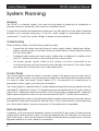
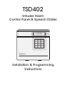
TSD402
Intruder Alarm
Control Panel & Speech Dialler
UNSET
1
4
2
5
3
6
7
8
0
9
HOME
AWAY
TSD402
Installation & Programming
Instructions
Contents
Regulatory Requirements . . . . . . . . . . . . . . . . . . . . . . . . . . . . . . . . . . . . . 1
General, Application & Approval . . . . . . . . . . . . . . . . . . . . . . . . . . . . . . . . . . . . . . .
Connections & Compatibility with PABXs . . . . . . . . . . . . . . . . . . . . . . . . . . . . . . . . .
Responsibility for Connection To Telephone Network . . . . . . . . . . . . . . . . . . . . . . . .
Ringer Equivalence Number (REN) . . . . . . . . . . . . . . . . . . . . . . . . . . . . . . . . . . . . . .
1
2
2
2
Overview . . . . . . . . . . . . . . . . . . . . . . . . . . . . . . . . . . . . . . . . . . . . . . . . . . 3
Introduction, Features & Control Panel Operation . . . . . . . . . . . . . . . . . . . . . . . . . . 3
Speech Dialler Operation. . . . . . . . . . . . . . . . . . . . . . . . . . . . . . . . . . . . . . . . . . . . . 4
Tone Dialling simulators (Tone Pads) & Specifications. . . . . . . . . . . . . . . . . . . . . . . . 5
System Planning. . . . . . . . . . . . . . . . . . . . . . . . . . . . . . . . . . . . . . . . . . . . . 6
General, Cable Routing, Control Panel & Remote Keypads . . . . . . . . . . . . . . . . . . 6
External Sounder & Detection devices . . . . . . . . . . . . . . . . . . . . . . . . . . . . . . . . . . . 7
Final Exit, Keyswitch & Power Supply Considerations. . . . . . . . . . . . . . . . . . . . . . . . . 8
System Installation . . . . . . . . . . . . . . . . . . . . . . . . . . . . . . . . . . . . . . . . . . . 9
Control Panel layout . . . . . . . . . . . . . . . . . . . . . . . . . . . . . . . . . . . . . . . . . . . . . . . . . 9
Installing the Control Panel . . . . . . . . . . . . . . . . . . . . . . . . . . . . . . . . . . . . . . . . . . . . 9
Mains Connection . . . . . . . . . . . . . . . . . . . . . . . . . . . . . . . . . . . . . . . . . . . . . . . . . 10
Battery Connection . . . . . . . . . . . . . . . . . . . . . . . . . . . . . . . . . . . . . . . . . . . . . . . . 10
Control Panel PCB Layout. . . . . . . . . . . . . . . . . . . . . . . . . . . . . . . . . . . . . . . . . . . . 11
Connections & Controls . . . . . . . . . . . . . . . . . . . . . . . . . . . . . . . . . . . . . . . . . . . . . 11
Connection Diagram . . . . . . . . . . . . . . . . . . . . . . . . . . . . . . . . . . . . . . . . . . . . . . . 15
Installing a TS400 Remote keypad . . . . . . . . . . . . . . . . . . . . . . . . . . . . . . . . . . . . . 16
Wiring the Auxiliary Dialler Inputs . . . . . . . . . . . . . . . . . . . . . . . . . . . . . . . . . . . . . . . 16
Telephone Line Connections . . . . . . . . . . . . . . . . . . . . . . . . . . . . . . . . . . . . . . . . . 17
Pre Power-Up Checks & Initial Power-Up . . . . . . . . . . . . . . . . . . . . . . . . . . . . . . . . . 18
Programming . . . . . . . . . . . . . . . . . . . . . . . . . . . . . . . . . . . . . . . . . . . . . . 20
Programming Menus . . . . . . . . . . . . . . . . . . . . . . . . . . . . . . . . . . . . . . . . . . . . . . .
Program Zones . . . . . . . . . . . . . . . . . . . . . . . . . . . . . . . . . . . . . . . . . . . . . . . . . . . .
View Event Log . . . . . . . . . . . . . . . . . . . . . . . . . . . . . . . . . . . . . . . . . . . . . . . . . . . .
Walk Test. . . . . . . . . . . . . . . . . . . . . . . . . . . . . . . . . . . . . . . . . . . . . . . . . . . . . . . . .
Exit Time . . . . . . . . . . . . . . . . . . . . . . . . . . . . . . . . . . . . . . . . . . . . . . . . . . . . . . . . .
Entry Time . . . . . . . . . . . . . . . . . . . . . . . . . . . . . . . . . . . . . . . . . . . . . . . . . . . . . . . .
Bell Duration Time . . . . . . . . . . . . . . . . . . . . . . . . . . . . . . . . . . . . . . . . . . . . . . . . . .
Change Engineer's Passcode . . . . . . . . . . . . . . . . . . . . . . . . . . . . . . . . . . . . . . . .
Remote Reset Number . . . . . . . . . . . . . . . . . . . . . . . . . . . . . . . . . . . . . . . . . . . . .
System Options. . . . . . . . . . . . . . . . . . . . . . . . . . . . . . . . . . . . . . . . . . . . . . . . . . . .
Speech Dialler Alarm Options . . . . . . . . . . . . . . . . . . . . . . . . . . . . . . . . . . . . . . . .
Returning to the Unset Mode . . . . . . . . . . . . . . . . . . . . . . . . . . . . . . . . . . . . . . . . .
Setting, Part-Setting & Unsetting the System . . . . . . . . . . . . . . . . . . . . . . . . . . . . . .
20
21
22
23
23
24
24
24
24
25
27
28
28
Installation Record . . . . . . . . . . . . . . . . . . . . . . . . . . . . . . . . . . . . . . . . . . 29
TSD402 Installation Manual
Regulatory Requirements
Regulatory Requirements
General
The TSD402 control panel must be installed by a electrically competent person. Before
attempting to install the unit, the installer must be aware of the following:
Application
The TSD402 is suitable for connection to the following types of telephone networks:
•
Direct exchange lines (PSTN) supporting DTMF (Tone dialling) or Loop Disconnect
(Pulse Dialling).
•
PABX exchanges (with or without secondary proceed indication).
+
The TSD402 is not suitable for connection as an extension to a pay phone or
1+1 carrier systems.
Approval
The TSD402 is approved for the following usage:
•
Automatic call initialisation
•
Operation in absence of proceed indication
•
Automatic dialling
•
Multiple repeat attempts
Usage other than the approved usage or failure to comply with the installation and
programming instructions may invalidate any approval given to the apparatus.
Note the approval Label on back of the control panel:
MENVIER SECURITY
TSD402
REN=0.0
POWER REQUIREMENTS 240V AC @ 200mA MAX
S/1100/3/R/503255
1
Regulatory Requirements
TSD402 Installation Manual
Connections
Connection terminals on the TSD402 are described as either "Safety Extra-Low Voltage"
circuits (S.E.L.V) or "Telecommunications Network Voltage" circuits (T.N.V).
The Printed Circuit Board (PCB) layout on page 11 shows the two types of circuits.
+
+
It is important that the installer ensures that T.N.V connections are only
connected to the PSTN and S.E.L.V circuits are only connected to other circuits
designated as S.E.L.V circuits.
Interconnection circuits should be such that the equipment continues to
comply with the requirements of 4.2 of EN 41003 for T.N.V circuits and 2.3 of EN
60950 for S.E.L.V circuits, after making connections between circuits.
Compatibility with PABXs
The TSD402 is only approved for use with compatible PABX systems. Correct operation in
all circumstances is not guaranteed. If you experience any difficulties contact Menvier
Technical Support.
Responsibility for Connection To Telephone Network
The person responsible for connection of the TSD402 to a PABX system is as follows:
1
If the wiring is owned by British Telecom PLC
a) British Telecom
2
If the wiring is not owned by British Telecom, either:
a) British Telecom
b)
The authorised maintainer
c)
A professional installer after 14 days written notice to the authorised maintainer.
Ringer Equivalence Number (REN)
The Ringer Equivalence Number for the TSD402 is 0.0 and as such any number can be
simultaneously connected to an exclusive line.
2
TSD402 Installation Manual
Overview
Overview
Introduction
The TSD402 is a 5 zone (+ Final Exit) control panel with an integral Speech Dialler. It is ideally
suited for domestic and small commercial installations, which require additional security
through the communication of audio alarm messages over the telephone line.
Features
•
5 Programmable zones Night, Access, Fire, PA & Keyswitch (plus common tamper)
•
Final Exit zone
•
Detector Reset output for Vibration and Smoke detectors
•
Internal and external volume controls
•
16 character Liquid Crystal Display (LCD)
•
2 user passcodes and engineers passcode
•
64 event log
•
Programmable Chime facility on all zones
•
Remote Reset facility
•
3 button Quick-Set for Home and Away
•
Program data stored in NVM (recorded messages are not)
•
Remote Keypad option (up to 4 x TS400 Remote Keypads)
•
Auxiliary trigger inputs for the speech dialler
•
Speech dialler activations may report to different telephone numbers
•
Built in microphone and speaker for record and play-back
•
Messages may be up to a total of 60 seconds in length
Control Panel Operation
Operation and programming is carried out from the tactile rubber keypad on the control
panel in conjunction with the 16 character LCD display.
There are two programming menus within the system. The engineer's programming menu
allows full system programming (zone types, view log, walk test, exit time, entry time, bell
duration time, engineers code, reset number, system options). The user programming
menu allows setting and unsetting of the system as well as allowing the user to test the
system. All speech dialler programming, configuration and testing is also carried out within
the "User Options" menu (for full details on speech dialler programming see User Manual).
3
Overview
TSD402 Installation Manual
The TSD402 incorporates a 3 button set facility which simplifies the setting and part-setting
of the system for user. When the user wishes to full set the system, they simply enter the first
2 digits of their passcode followed by the AWAY key. To part-set the system, they simply
enter the first 2 digits of their passcode followed by the HOME key. When unsetting the
system the user must enter all 4 digits of the passcode.
Speech Dialler Operation
The speech dialler may be configured by the engineer to trigger on FIRE, P.A. or ALARM
activations for both the Away set and Home set. In addition to alarm triggers provided
internally from the control panel, there are 3 auxiliary inputs which may be used by other
devices to trigger the speech dialler independently from that of the control panel.
Telephone
Numbers
-
The TSD402 stores up to three different telephone numbers. Each
number may be up to 16 digits long and are simply
programmed using the text display and keypad on the unit. The
unit is compatible with most PABX systems that require a pause
or wait for secondary dial tone. Note: The Emergency Service
numbers (999 &112) cannot be programmed into the unit.
Messages
-
The TSD402 has a built-in microphone and speaker so that
phrases can be recorded and replayed directly from the unit. A
message is formed by combining a common phrase (0) and
one of the alarm phrases (F, P or A). When the out-going call is
answered the unit plays the common phrase (0) and one of the
three alarm phrases F, P or A. Phrase 0 states the name and
address of the user and phrases F, P and A relate to the alarm
type (FIRE ,PA, ALARM). There is 60 seconds of recording time
available for phrases and each phrase can be any length as
long as the total does not exceed 60 seconds. For example, the
"Common Phrase" may be 12 seconds, "Phrase F" 5 seconds,
"Phrase P" 8 seconds and "Phrase A" 7 seconds.
Reporting Options
-
Each alarm type (F, P or A) may be programmed to report only
to selected telephone numbers. For example the Fire activation
may be programmed to report to all three telephone numbers,
whereas the Alarm activation may be programmed to report
only to telephone numbers 1 and 3 etc.
Call
Acknowledgement
-
When the call is answered, the message is played. At the end of
the message the unit sends an audible "bleep" which must be
answered within 2 seconds using the tone generated by pressing
the number [8] button on a standard telephone. On hearing the
[8] tone the unit immediately sends a second "bleep" which must
be answered in the same way. If successful, a multi-tone
confirmation signal is then heard, if not then the message is
4
TSD402 Installation Manual
Overview
repeated with the acknowledgement "bleeps" again. If the call
is not acknowledged at the end of the fifth play of the message
the unit abandons that call and attempts the next telephone
number. This procedure is repeated three times in sequence for
all three telephone numbers. If no acknowledgement has been
received then the speech dialler shuts down.
Acknowledgement
Options
-
The TSD402 may be programmed to stop dialling after the first
call has been acknowledged or when two, or three have been
acknowledged. The acknowledgement may also be disabled
altogether, when the speech dialler is used in this mode it dials
the first telephone number and providing the call is answered it
plays the message and shuts down. If the call is not answered it
dials the next telephone number etc.
Aborting a Call
-
If the system is accidentally triggered the speech dialler is
automatically shut down when a valid user passcode is entered.
Tone Dialling simulators (Tone Pads)
For the acknowledgement procedure to work successfully the TSD402 "looks" for a 1 second
of tone between 600Hz and 1400Hz. This is supplied most reliably by the [8] button used
for MF dialling although other buttons may work if pressed accidentally.
If the recipients telephone cannot produce a suitable tone then a "Tone Dialling Simulator"
(Tone Pad) may be required. These are available from many high street electrical stores
and also from specialist suppliers such as RS Components (stock code 252-841) and
Maplin Electronics (stock code CK25C).
Specifications
Panel Input Voltage:
Current Consumption:
Auxiliary power:
Remote Keypad:
Trigger inputs (speech dialler):
REN Value:
BT Approval number:
Control Panel Dimensions:
Remote Keypad Dimensions:
Control Panel Weight:
Battery Size
Case Construction:
Environment:
240V +/- 10% 50Hz
80 mA
13.8v @ 300 mA
TS400REM (normal 20mA, alarm 32mA)
+ve or -ve applied, input voltages 5 - 28V
0
S/1100/3/R/503255
205 (W) x 205 (H) x 64 (D) mm
130 (W) x 130 (H) x 30 (D) mm
1.4 Kg
2.1Ah
3mm Polycarbonate
0 - 55°C
5
System Planning
TSD402 Installation Manual
System Planning
General
The TSD402 is a flexible system, but care must be taken in planning the installation to
provide maximum protection with minimum installation effort.
Survey the household and determine where each security device is to be fitted. Wherever
possible, try to conceal wiring (e.g., in the loft, under carpets or floorboards and inside
cupboards). Commit the system design to paper for easy reference.
Cable Routing
When installing cables, the following should be noted:
•
Ensure that all cables are kept clear of mains supply cables, telephone cables,
cables supplying bells or sounders and any cables likely to induce electrical noise
(R.F.)into the system.
•
Screened cable may prove necessary if cables are run adjacent to cables which
carry R.F. (electrical noise) or are switching high current loads.
•
The mains power supply cable to the system must be connected to an
un-switched fused spur that cannot be accidentally switched off. The mains cable
must enter the housing via its own cable entry point.
Control Panel
The control panel should be sited in a position where it has easy access for the users to
set and unset the system. It should also be mounted in a well lit area and at a level where
it is easy to read the Liquid Crystal Display (LCD). The provision for connecting to a
permanent mains supply must also be considered.
The control panel is supplied with a 2 metre telephone lead which plugs directly into any
standard B.T. telephone socket, it is therefore recommended that the unit is also sited as
near to a B.T. telephone socket as possible. If this it not possible an approved B.T. extension
lead may be required or the unit can be hard wired to the B.T. socket (see Installation).
When operating the system it should be possible to hear the exit and entry tones throughout
the exit/entry route and outside the final exit door. If the control panel is sited along way
from the final exit door it may be necessary to fit an extension loudspeaker.
Remote Keypads
If required, up to four remote keypads may be connected to the system to allow remote
setting and unsetting of the system. The remote keypad uses LED indicators to show zone
faults and alarms, and has an internal sounder to indicate exit and entry tones. Remote
keypads require a six-core cable for connection.
6
TSD402 Installation Manual
System Planning
External Sounder
The External Sounder should be mounted as high as possible so that it is visible and out of
reach to potential intruders. A six core cable is required for connection to the sounder, it
should enter directly through the wall and into the sounder via the cable entries in the back
plate. However, if the cable is run over the surface to the sounder then it should be
protected (e.g., the cable may be run in aluminium conduit).
Detection devices
There are several types of detection devices available which are suitable for domestic
installations as follows:
Passive Infra-Red
(PIR)
-
A movement detector which detects movement of an intruder
by the change in infra-red body heat. When fitting PIRs, refer to
the installation instructions supplied with the unit.
In general there are two types of PIR "Standard" and "Latching".
Normally the standard type is used where one detector per zone
is fitted. A six core cable is required for connection.
The latching type is used when more than one detector is fitted
to a zone, the latch facility allows the user to identify the triggered
detector by means of the indicator LED on the detector "latching"
on. If latching detectors are used an eight core cable is required
for connection.
Magnetic
Contacts
-
Magnetic contacts consist of an electrical switch which is
operated by a magnet. They come in two varieties, the "Flush"
type is designed to be fitted into the top or side of the
door/window. The "Surface" type is designed to fitted to
doors/windows where it is not possible to use flush contacts e.g.
garage doors, UPVC windows etc. Both types of contacts require
a four core cable for connections.
Personal Attack
(PA) Button
-
Normally PA buttons are located by the front door or adjacent to
the bed, and preferably out of reach to small children. Pressing the
button at any time will generate a full alarm. After pressing the
button, it must be reset with the key provided and then reset at the
control panel. PA buttons require a four core cable for connections.
Vibration Detectors
-
Vibration detectors are normally fitted to windows or door frames.
They are triggered when the device senses a shock attack.
Vibration detectors require a six core cable for connections.
Smoke/Heat
Detectors
-
12V Smoke or heat detectors may be connected to the system
to provide additional protection against fire. When activated a
distinctive internal sounder tone is generated and the external
sounder is pulsed. Smoke detectors require a four core cable for
connections.
7
System Planning
TSD402 Installation Manual
Final Exit
This is the point at which the user leaves and enters the premises (normally the front door).
When setting the system the user must leave the premises via the exit route and through
the Final Exit zone. When re-entering the premises the user must activate the Final Exit zone
to start the entry timer which allows the user time to gain access to the control panel to
unset the system. If the user enters the premises through any other point and triggers a
detection device a full alarm will be generated.
The system may be programmed to set after the exit timer has expired or by the operation
of the Final Exit detection device.
Keyswitch
An optional keyswitch may be fitted to the system to allow the user to set and unset (or
part-set and unset) the system using a physical key rather than a four digit passcode.
Power Supply Considerations
The maximum current available from the control panel power supply is 750mA. The total
current consumption of all devices (Panel, detectors, sounders, strobes battery charge
etc.) that are connected to the system must not exceed 750mA.
The following is a typical example on how the total current is calculated. When calculating
the total current for your own installation refer to the manufacturers specifications on each
device.
Total available current from control panel = 750mA
Control panel
External Strobe
= 80mA
+
= 250mA
+
= 120mA
Total Current
= 450mA
Auxiliary Current
= 300mA (750 -450)
External Sounder
From the above calculation example there is 300mA available for powering detection
devices etc.
8
TSD402 Installation Manual
System Installation
System Installation
Control Panel layout
Mains Cable
Entry
Cable Entry
PCB
Supports
Loudspeaker
(Under PCB)
Holders for
spare fuses
PCB
Fused
Terminal
Block
(200mA)
PCB
Clips
Transformer
+
Cover
Clips
Battery
2.1 Ah
max.
Figure 1
TSD402 Control Panel layout
Installing the Control Panel
+
For your safety, installation of the TSD402 must be conducted in the following
sequence.
1
Remove the screw from the top of the control panel and lift away the front cover.
2
Ensure that there is no battery in the housing, then remove the PCB as follows:
a) Disconnect the AC leads from the transformer and unplug the internal
loudspeaker from the Printed Circuit Board (PCB).
9
System Installation
TSD402 Installation Manual
b)
Pull down the plastic clip at the bottom right hand corner of the PCB and gently
lift the PCB forward.
c)
Repeat with the plastic clip at the bottom left hand corner of the PCB.
d)
The bottom of the PCB will then swing forward and the whole PCB will come away
from the base.
3
Hold the base in the required position and mark the centre of the keyhole positions.
Remove the base, then drill and plug the holes. Note: Remember to allow enough
room to get the cover screw in to top of panel when mounting the base.
4
Re-position the base and secure to the wall with 3 x No. 10 11⁄4" wood screws.
5
If a remote keypad is being fitted to the system, refer to page 16.
6
Re-fit the PCB assembly by aligning the top of the PCB into the 2 supports in the top
of the housing ensuring that the edges of the board sit between the 2 flanges, then
push the bottom of the PCB until it clicks in place.
7
Re-connect the AC leads to the transformer.
8
Connect the mains to the fused terminal block in the panel via an un-switched fused
spur, ensuring that the cables enters the housing via its own cable entry point.
Mains Connection
The mains supply is connected to a 3 way "Euro Type" fused terminal block. To comply
with BS4737 the supply should be fed from an un-switched fused spur fitted with a 3A fuse.
All electrical connections should be carried out by a technically competent person and
must comply with the current IEE regulations.
Battery Connection
A 2.1Ah battery must be fitted to the control panel to allow the system to function during
a mains fail condition.
The TSD402 is equipped with a "Battery Protection" circuit so that if a battery is accidentally
reverse connected or its voltage is below 8V, the "Battery Fault" LED illuminates. To clear
the fault simply reconnect or replace the battery as appropriate.
10
TSD402 Installation Manual
System Installation
Control Panel PCB Layout
Factory Restart Pins
Auxiliary Trigger Input
Polarity Selector
Bell Fuse (1 Amp)
JP3
Flying Leads
to T ransformer
FACT OR Y
REST AR T
Zone
Connections
(S.E.L.V Circuit)
A
P
F
Auxiliary Dialler
Trigger Inputs
(S.E.L.V Circuit)
16 Character LCD Display
Remote Keypad
Interface socket
(S.E.L.V Circuit)
INT. VOLUME
VR2
Internal Volume Control
JP2
Connection to
Internal Speaker
SPEAKER
1
2
3
Microphone
4
5
6
Tactile Rubber Keypad
7
8
9
HOME
0
AWAY
A
B
BC
A.C.
Figure 2
TRIGGER
VR1
EXT. VOLUME
TRIG POLARITY
L/SAUX 12V P.A.
FIRE
K'SW ACCESS ACCESS
- 5 ZONE 4 ZONE 3 ZONE 2 ZONE 1 F/EXIT
- +
ZONE
Aux 12V Fuse
(1 Amp)
ALM RST TRG STB + H/O TMP
AUX
- - TAMPER
EXTERNAL BELL
T amper Switch
JP1 +
Extension Speaker Volume Control
Telephone Line
Connection Terminals
(T.N.V Circuit)
TSD402 PCB Layout
Connections & Controls
The main PCB has the following "Jumper Plugs" (JP), indicator LEDS and terminal
connections:
TRIG POLARITY (JP1) - This jumper-link sets the signal polarity for the auxiliary speech
dialler trigger inputs. The inputs may be either +ve applied to
trigger or -ve applied to trigger.
SPEAKER (JP2)
-
The internal loudspeaker has a 2-way connector which plugs
directly on to this set of pins.
FACTORY RESET
(JP3)
-
All program data (Not messages) is stored in a Non-Volatile
Memory chip (NVM). If the Factory Reset pins are shorted during
power-up all stored system parameters are over written with the
factory default settings. The engineer passcode is reset to 1234
and the User 1 passcode is set to 5678.
11
System Installation
TSD402 Installation Manual
Connections & Controls (Cont.)
EXT. VOLUME (VR1)
-
If an extension loudspeaker is connected to the control panel,
the volume of keypad bleeps, chime, entry and exit tones may
be adjusted using this control (clockwise to increase). Alarm
tones are always full volume.
INT. VOLUME (VR2)
-
This controls the volume of keypad bleeps, chime, entry and exit
tones from the internal loudspeaker (clockwise to increase). The
volume of the speech dialler playback messages are always full
volume.
F/EXIT
-
This pair of terminals is for connecting to the Final Exit detection
device, normally a set of magnetic contacts on the front door.
The tamper loop should be connected in series with other loops
across the terminals mark AUX TAMPER (see Connection
diagram).
ZONE 1 (Access)
-
This pair of terminals may be connected to any type of normally
closed detection device. When activated during a set condition,
a full alarm is generated. It is also possible to program the zone
as "Access" this allows the detector to be activated during entry
and exit when setting/unsetting the system. If the zone is
programmed as "Access" and is armed during a part-set (Home)
condition it will start the entry timer if activated. The tamper loop
should be connected in series with other loops across the
terminals mark AUX TAMPER (see Connection Diagram).
ZONE 2 (Access)
-
As Zone 1.
ZONE 3 (K'SWITCH)
-
This pair of terminals may be connected to any type of normally
closed detection device. When activated during a set condition,
a full alarm is generated. It is also possible to program the zone
as "Keyswitch" this allows the zone to be connected to an
electrical keyswitch to set and unset the system. The keyswitch
functionality maybe further programmed to either full set (Away)
or part-set (Home) the system. (see Programming). The tamper
loop should be connected in series with other loops across the
terminals mark AUX TAMPER (see Connection Diagram).
ZONE 4 (Fire)
-
This pair of terminals may be connected to any type of normally
closed detection device. When activated during a set condition,
a full alarm is generated. It is also possible to program the zone
as "Fire" this allows the zone to be connected to any type of
normally closed smoke or heat detector. The tamper loop should
be connected in series with other loops across the terminals mark
AUX TAMPER (see Connection Diagram).
12
TSD402 Installation Manual
System Installation
ZONE 5 (PA)
-
This pair of terminals may be connected to any type of normally
closed detection device. When activated during a set condition,
a full alarm is generated. It is also possible to program the zone
as "PA" this allows the zone to be connected to any type of
normally closed PA buttons. The tamper loop should be
connected in series with other loops across the terminals marked
AUX TAMPER (see Connection Diagram).
AUX 12V +/-
-
The auxiliary 12V terminals provides permanent 12V @ 300mA
of power for detectors which require a low voltage supply e.g.,
PIR's, Vibration Detectors, Smoke Detectors etc. The output is
protected by a 1 amp fuse (Aux 12V).
L/S -
-
A 16Ω extension loudspeaker may be connected between L/Sand AUX 12V+ terminals. The loudspeakers will reproduce all
alarm and advisory tones generated by the control panel.
+
If an extension loudspeaker is fitted to the system it
must be sited more than 0.5 metres from the control
panel. The play-back of speech dialler messages are
not reproduced at the extension loudspeaker.
AUX TAMPER
-
The tamper protection for all devices must be connected in
series then connected to this pair of terminals.
TMP-
-
This terminal provides the tamper protection to the external
sounder. It should be connected to the negative tamper return
output on the external sounder. If the external sounder is not
required to be tamper protected, this terminal must be linked to
H/O -.
H/O -/+
-
The "Hold Off -" and "Hold Off +" terminals provide permanent
12V hold off supply for the external sounder or SAB module. The
output is protected by a 1 amp fuse (Bell Fuse).
STB -
-
This terminal provides the switched negative strobe trigger output
(max. 500mA). It should be connected to the -ve strobe input on
the external sounder or SAB module.
The strobe output is activated on all types of alarm (Fire, PA and
Alarm), the output will only deactivate when the triggered alarm
is fully reset.
If a zone remains in a fault condition when the system attempts
to set, the strobe output is activated to give the user external
indication that the system has failed to set.
13
System Installation
TSD402 Installation Manual
Connections & Controls (Cont.)
TRG -
-
This terminal provides the switched negative bell trigger output
(max. 500mA). It should be connected to the -ve bell trigger
input on the external sounder or SAB module. The output may be
programmed for SAB or SCB operation:
SAB
When programmed as SAB, the output will switch to 0V on alarm.
SCB
When programmed as SCB, the output provides a 0V hold off,
which is removed on alarm.
RST -
-
This terminal may be programmed as either:
Detector Reset
This type of output is used to power detectors which latch their
alarm condition (e.g., smoke detectors, vibration detectors
etc.). Power for such detectors must be connected between
AUX 12V+ and RST-. Following a full alarm the power to this
output is momentarily removed when the user/engineer has
reset the system, this will allow the such detectors to "Reset".
Switched 12V
When programmed as "Switched 12V" the output may be
connected to the latch input terminal on latching detectors
(e.g., PIRs etc.). This feature is normally used when more than
one detector is connected to a single zone. It allows the user to
identify the alarm source by latching the indicator LED on the
detector that caused the alarm activation. The latched LED will
clear when the system is reset.
ALM -
-
This terminal is switched negative (100mA) on alarm and is
removed when the system is reset.
TRIGGER F,P & A
-
These terminals are the auxiliary Fire, PA and Alarm trigger inputs
for the speech dialler, they may be used to trigger the the unit
independently from that of the control panel. For example, a
smoke detector could be directly connected to input "F", when
activated it would trigger the "Fire" message on the speech
dialler but not cause the control panel to alarm.
A, B & BC
-
These terminals are for the telephone line connections, they must
be connected to an approved "B.T. Master socket" or "Extension
socket" using the lead provided (see BT Connections).
14
TSD402 Installation Manual
System Installation
Connection Diagram
External Sounder
TSD402
TRIGGER STROBE HOLD OFF +
HOLD OFF TAMPER RETURN -
ALARM
PIR
To Zone 1
ALM RST TRG STB+
- H/O
TMP AUX
TAMPER
L/S + AUX 12V
-
Terminal Strip
(Not supplied)
TAMPER
0V
+12V
To AUX 12V To AUX 12V +
ZONE 5 (P A)
ZONE 4 (Fire)
ALARM
To Zone 2
ZONE 3 (K/Sw)
PIR
TAMPER
ZONE 2 (Access)
0V
+12V
To AUX 12V To AUX 12V +
ZONE 1 (Access)
FINAL EXIT
To Zone 3
Surface Contact
To FINAL EXIT
Flush Contact
To Zone 5 (P .A.)
P.A. Button
Note
Any unused Zones must be
linked out.
PIRs and Surface Contacts may
be connected to any zone. This
diagram is only used to
represent a typical installation
example.
If a Keyswitch is fitted, it must
be connected to Zone 3 and
then programmed as
KEYSWITCH.
If a Smoke/Heat Detector is
fitted, it must be connected to
Zone 4 and then programmed
as FIRE.
If a P.A. Button is fitted, it must
be connected to Zone 5 and
then programmed as P.A.
Smoke Detector
Supply +
Supply ALARM
Figure 3
To AUX +12V
To RST To ZONE 4
=
16 Ohm Extension Loud speaker
(cut R37 to reduce volume)
Sample Connection Diagram
15
System Installation
TSD402 Installation Manual
Installing a TS400 Remote keypad
Up to four TS400 remote keypads may be connected to the TSD402 control panel. The
remote keypad is supplied with an interface PCB which plugs onto the main PCB. Remote
keypad(s) may be sited up to a maximum of 50 metres from the control panel using a
six-core cable for connections.
+
The TS400 remote keypad is only suitable for setting, part-setting, unsetting and
limited programming functions. All other system operations must be carried out
at the control panel.
1
Remove the TSD402 PCB from the case (see page 9 for full details)
2
Connect each core of the six-core cable to the interface terminals "LEDCBA" (make
a note of the colours used for each connection).
3
Pass the yellow flying-lead behind the PCB and connect it to the L/S-terminal.
4
Plug the interface PCB onto the TSD402 PCB (see figure 2 on page 11).
5
Replace the TSD402 PCB.
6
Separate the remote keypad cover and base by using a screwdriver to push two of
the clips (top or bottom) inwards from the cover retaining slots. Then lift the cover
assembly away, noting that the PCB is connected to the under side of the cover.
7
Hold the remote keypad base in position (keyhole to the top) and mark the three
securing holes, drill and plug the wall as required. Pass the six-core cable into the
base via the cable entry points as appropriate and secure the base to the wall.
8
Connect each core of the six-core cable to the remote keypad terminals "EDCBAL",
ensuring that the connections through to the control panel are A-A, B-B, C-C etc. If
more remote keypads are to be fitted, they may be connected in a "Star" or
"Daisy-chain" configuration (providing the cable length to the last or furthest remote
keypad does not exceed 50 meters).
9
Carefully reattach the front cover assembly to the remote keypad base ensuring that
all cables are clear of the tamper switch spring and the cover is securely clipped to
the base.
Wiring the Auxiliary Dialler Inputs
The auxiliary speech dialler inputs may be connected to devices that are required to signal
the speech dialler independently from the control panel. The inputs may be selected for
various types of signalling as shown in Figure 4.
16
TSD402 Installation Manual
System Installation
TRIG POLARITY
-
TRIG POLARITY
+
-
AUX 12V
TSD402
+
AUX 12V -
+
TRIGGER
A
P
F
N.C.
Loop
1KW
resistor
N.O.
Loop
TSD402
12V on alarm
N.O.
Loop
TRIGGER
A
P
F
N.C.
Loop
1KW
resistor
0V on alarm
Alarm input = Normally Open
PA input
= Normally Closed
Fire input = Switched -ve
Alarm input = Normally Closed
PA input
= Normally Open
Fire input = Switched +ve
Figure 4
+
Signalling Types for Auxiliary Dialler Inputs
Telephone Line Connections
There are two methods of connection for the TSD402 to the telephone line. The first is to
use the 2 metre lead supplied (recommended method of connection) which will directly
plug into any standard British Telecom telephone socket. The second is to directly connect
the unit to an NTE5 Master Socket (Line Box). Figure 5 shows both methods of connection.
TSD402
White
Red
Blue
A
B
BC
Standard BT telephone plug
Connection using the lead supplied
BT Master Jack (NTE5)
User accessible connections
6
5
4
Cable type 1/0.5mm CW1308
White/Blue ring
TSD402
3
2
1
Blue/White ring
Orange/White ring
A
B
BC
Direct method of connection
Figure 5
The Two Methods of BT Line Connections
17
System Installation
TSD402 Installation Manual
Pre Power-Up Checks
Before applying any power to the system, give the system one final check to ensure that:
1
The telephone lead is unplugged from the telephone socket.
2
The wiring and connections conforms to the requirements detailed in this manual.
3
All system cables are kept clear of mains supply cables, telephone cables and R.F.
cables. It is recommended that cable ties be used to keep cables separated.
4
Calculate the total system power consumption and ensure that it does not exceed 750mA.
5
Mains supply cables to the system are connected to an un-switched fused spur.
Initial Power-Up
1
Place a small screwdriver blade between the pins on the Control Panel PCB, marked
FACTORY RESTART (located top left corner). This will ensure that the factory default
values are loaded into memory as show below:
Engineer's Passcode
User 1 Passcode
User 2 Passcode
Zone 1
Zone 2
Zone 3
Zone 4
Zone 5
Final Exit
Exit Time
Entry Time
Bell Duration
Remote Reset Number
Bell Output
Setting Mode
Reset Authority
Number of Re-arms
Operation of Key Switch
Operation of RST- Output
Operation of Final Exit in P/Set
HOME Setting
Dialler Alarm Options
Acknowledgement Option
18
-
1234
5678
Not programmed
Night
Access
Night
Night
Night
Exit
030 Seconds
030 Seconds
020 Minutes
004
SAB (-ve Applied)
Timed Exit
User Reset
3
AWAY Set (Full)
Switched 12V
Final Exit
Zone 1 Omitted
No Alarms Report
Cleared by any 1
TSD402 Installation Manual
System Installation
Initial Power-Up (Cont.)
2
Switch on the 240V mains supply and remove the screwdriver blade. The internal
alarm will bleep every 30 seconds the display will show: CFT.
3
Connect the standby battery. If the display shows: BATT. FLT and the internal
alarm sounds, then the battery may have been incorrectly connected or its voltage
is below 8V. Disconnect the battery immediately and reconnect or replace as
appropriate.
4
Push the battery into place at the bottom of the housing and re-fit the front cover.
5
The display will show: PLEASE RE-RECORD, this message will only be cleared
when one or more of the speech dialler messages has been recorded (see User
Manual for full details).
6
Enter the engineer's passcode (default 1 2 3 4 ), the display will show:
ENGR. OPTION - (engineer programming menu selected)
7
The telephone lead can now be plugged into the telephone socket.
8
Fit the battery link in the external siren and replace cover.
9
The system is now ready for engineer programming.
19
Programming
TSD402 Installation Manual
Programming
Programming Menus
There are two programming menus within the system. The engineer's programming menu
and the user programming menu. The figure below shows the structure of both
programming menus, however the engineers programming menu is only covered in full
detail within this manual. For full details on the user programming, see User Manual.
Either menu can be accessed from the unset condition, however the function of the HOME
and AWAY keys change once the programming menu is selected. The HOME key functions
as the ENTER key and the AWAY key functions as the ESCAPE key.
Engineer's Option Menu
UNSET
Enter Engineer's Passcode
(Default 1 2 3 4 )
ENGR. OPTION -
User Options Menu
UNSET
Enter first 3 digits of Passcode then [
(e.g., 5 6 7 [ )
USER OPTION -
1 = Program Zones
1 = Bell Test
2 = View Event Log
2 = Walk T est
3 = Walk T est
3 = Remote Reset *
4 = Exit T ime *
4 = Change Passcode 1 *
5 = Entry T ime *
5 = Change Chime Zones
6 = Bell Duration *
6 = Change Passcode 2 *
7 = Change Engineer's Code *
7 = Home Area Configuration
8 = Change Remote Reset No. *
8 = Dialler Programming *
9 = System Options
9 = View Event Log
0 = Dialler Alarm Options
0 = Dialler Reporting Options *
] = Return to Unset mode
] = Return to Unset mode
* These options cannot be programmed using the remote keypad.
20
TSD402 Installation Manual
Programming
Program Zones (key 1 )
The TSD402 zones may be programmed so that they perform different functions. The zones
types are as follows:
Night (N)
- Zones 1-5 may be programmed as a Night zone, this type of
zone will only generate a full alarm when activated during a set
condition. If during a full alarm condition the speech dialler Alarm
channel is programmed to report, it will activate and send the
Alarm message.
Access (A)
-
Zones 1 and 2 may be programmed as an Access zone, this
type of zone is automatically isolated during the entry/exit
procedure to allow a "walk through" route for the user. Once the
system is full set the Access circuit responds as a Night circuit. If
an Access zone is armed during a part-set (HOME) condition it
will start the entry timer if activated.
Key switch (S)
-
Zone 3 may be programmed as a Keyswitch zone, this type of
zone will set the system when active (zone open) and unset the
system when healthy (zone closed). The Keyswitch zone
functionality may be further programmed to either full set (AWAY)
or part-set (HOME) the system (see System Options).
Fire (F)
-
Zone 4 may be programmed as a Fire zone, this type of zone is
monitored at all times, when activated a distinctive internal
sounder tone is generated and the external sounder is pulsed. If
during a fire alarm condition the speech dialler Fire channel is
programmed to report, it activates and sends the Fire message.
P.A. (P)
-
Zone 5 may be programmed as a Personal Attack (P.A.) zone,
this type of zone is monitored at all times, when activated a full
alarm is generated. If during a PA alarm the speech dialler P.A.
channel is programmed to report, it will activate and send the
P.A. message.
Final Exit (E or A)
-
The Final Exit zone is the last detector that is activated when
leaving the protected premises and the first detector to be
activated when re-entering the protected premises. This zone
may programmed to respond as follows:
Exit (E) When programmed as Exit the Final Exit zone will
generate an interrupted tone when opened during the Exit
procedure.
Access (A) When programmed as Access the Final Exit zone
will remain silent when opened during the Exit procedure. The
feature is useful if a PIR is used for the Final Exit zone, as it will
normally be activated several times before leaving the building.
21
Programming
TSD402 Installation Manual
Program Zones (Cont.)
1
Ensure that the "ENGR. OPTION -" is displayed. Press 1 to select Program Zones.
2
Press keys 1 to 6 to toggle between the two options for each zone (as Shown Below).
3
When completed, press [ to accept, a two tone acceptance tone will be heard.
Zone 3 = Night
Zone 2 = Night
Zone 4 = Night
Zone 5 = Night
Zone 1 = Night
F/Exit = Exit
E1- N N N N N E
Zone
Programming
Display
Press
Key To
T oggle
1 23 4 56
E1- A
A
S
F
P
Zone 1 = Access
A
Final Exit = Access
Zone 5 = P A
Zone 2 = Access
Zone 3 = Keyswitch
Zone 4 = Fire
View Event Log (key 2 )
The TSD402 will store up to 64 events within the memory log. When this option is selected
the most recent event is displayed first. Pressing the [ key takes you backwards through
the Log and pressing the ] key abandons the View Log option. Table 1 shows event log
descriptions.
Display
AC OFF
Description
Mains power removed.
AC ON
Mains power restored.
AU PL TA
Auxiliary or panel lid tamper alarm.
BATT FLT
Battery fault (battery reversed or below 10.5V).
CCT AL -
Full alarm from zone 1 - 5 (F = Final Exit when part-set).
CODE TA
Code Tamper (4 incorrect passcode entries).
ENTRY TO
Entry timed-out (system not unset after activating F/Exit zone).
FIRE AL
Fire Alarm activated.
SET A
AWAY Set.
SET FAIL
System failed to set (zone still active at end of exit time).
SET H
HOME Set.
USER -
User 1 or 2 passcode entered (User 3 = keyswitch).
--------
No Event
Table 1 Log Event Codes and Descriptions
22
TSD402 Installation Manual
Programming
View Event Log (Cont.)
1
Ensure that the "ENGR. OPTION -" is displayed. Press 2 to select the View Log option.
2
Press the [ key to move backwards through the Log.
3
When completed, press ] to abandon the View Log option.
Walk Test (key 3 )
The Walk Test option allows the engineer to test the function of all detection zones without
causing an alarm. As each zone is activated the zone number is displayed and the internal
sounders generate a two-tone sound. When the zone is deactivated the sounder will stop,
but the display will latch the activated zone.
1
Ensure that the "ENGR. OPTION -" is displayed. Press 3 to select the Walk Test option.
2
Activate each zone in turn by opening doors fitted with alarm contacts and walking
in front of movement detectors. The display will show the activated zones (as shown
below).
3
When completed, press ] to abandon the Walk Test option.
NONE
Walk Test /
Circuit Fault
Display
Activate each zone
CF- 1
Zone 1
Zone 2
Zone 3
Zone 4
2
3
4 5 F T
Tamper
Final Exit
Zone 5
Exit Time (key 4 )
This timer sets the delay between the user initiating the setting procedure and the system
actually setting. This only applies when the system is programmed to set by "Timed Exit"
(see System Options). The timer may be set between 1 and 255 seconds.
1
Ensure that the "ENGR. OPTION -" is displayed. Press 4 to select the Exit Time option.
2
Enter the timer setting using the number keys e.g., to set the Exit Time to 15 seconds,
enter "0 1 5".
3
When completed, press [ to accept, a two tone acceptance tone will be heard.
23
Programming
TSD402 Installation Manual
Entry Time (key 5 )
When the entry procedure is initiated, the Entry Timer is started and the display counts down
the remaining time. If a valid user passcode is not entered when the timer reaches zero,
a full alarm tone is generated from the internal sounders only and the timer is restarted. If
a valid user passcode is not entered when the timer reaches zero for the second time the
external sounder is activated. The timer may be set between 1 and 255 seconds.
1
Ensure that the "ENGR. OPTION -" is displayed. Press 5 to select the Entry Time option.
2
Enter the timer setting using the number keys e.g., to set the Entry Time to 25 seconds,
enter "025"
3
When completed, press [ to accept, a two tone acceptance tone will be heard.
Bell Duration Time (key 6 )
This timer controls the duration of the external sounder when the system is triggered into a
full alarm condition. The timer may be set between 000 and 255 minutes, when the timer
is set to "000" the output becomes continuous.
1
Ensure that the "ENGR. OPTION -" is displayed. Press 6 to select the Bell Duration Time
option.
2
Enter the timer setting using the number keys e.g., to set the Bell Duration Time to 10
minutes, enter "010"
3
When completed, press [ to accept, a two tone acceptance tone will be heard.
Change Engineer's Passcode (key 7 )
The factory default engineer's passcode is set to 1 2 3 4, but the installation engineer should
change this to their own personal 4 digit passcode as follows:
1
Ensure that the "ENGR. OPTION -" is displayed. Press 7 to select the Change Engineer's
Passcode option.
2
Enter the new passcode using the number keys e.g., to set the passcode to 2580
enter "2580"
3
When completed, press [ to accept, a two tone sound indicates acceptance, a
single low tone sound indicates that the new passcode was not accepted. Repeat
the procedure, trying a different passcode.
Remote Reset Number (key 8 )
The "Engineer Reset" option may be overridden by the user, operating the "Remote Reset"
facility. If an alarm is generated the system will respond with a four digit "seed" code which
the user quotes to the alarm company. The "seed" code is then entered into a decoder
and a unique "Remote Reset" code is generated. This is passed back to the user and, on
entering the "Remote Reset" code, the system will reset.
24
TSD402 Installation Manual
Programming
Remote Reset Number (Cont.)
The "Remote Reset" code is generated using an algorithm identified by a 3 digit number.
Alternative algorithms may be selected but these must correspond to that used by the
alarm company otherwise the "Remote Reset" code will be incorrect.
The "Remote Reset" feature may be disabled altogether by setting the number to "000"
1
Ensure that the "ENGR. OPTION -" is displayed. Press 8 to select the Remote Reset
Number option.
2
Enter the Remote Reset Number using the number keys e.g., to set the number to
000 (disable Remote Reset) , enter "000"
3
When completed, press [ to accept, a two tone acceptance tone will be heard.
System Options (key 9 )
The TSD402 has six system options which change the functionality of the system. The options
are as follows:
Bell Output Type
SAB (A)
When programmed as SAB the output will switch to 0V on alarm.
SCB (C) When programmed as SCB the output provides a 0V
hold off, which is removed on alarm.
Setting Mode
Timed Exit (T)
The system will set when the Exit timer has expired.
Final Exit (F)
The system will set when the last detector or door contact is
activated during the exit procedure.
Note: When the system is part-set (HOME) the system will always
set by Timed Exit and is Silent.
Reset Authority
User Reset (U)
Following an alarm the system can be reset by the user.
Engineer Reset (E)
Following an alarm the system can only be reset by the engineer
or Remote Reset (If enabled).
25
Programming
Re-arm Options
TSD402 Installation Manual
1 re-arms (1)
When an alarm occurs, the internal and external sounders are
operated for the length of the bell duration. At the end of this
time the alarm is silenced and the all zones are re-armed. Any
zones that are active will be automatically isolated until they
return to their healthy state. If an alarm occurs from the same
zone it will cause the internal and external sounders to operate
again, at the end of the alarm the zone is "Locked-out" and
prevented from generating another alarm. All other healthy
zones will re-arm and will only be "Locked-out" when they have
caused another alarm.
3 Re-arms (3)
Operates as above, but zones are only "Locked-out" after the
system has re-armed 3 times.
Key Switch Options
AWAY (A)
When key switch zone is opened the exit procedure for AWAY set
will start and when exit timer has expired or the Final Exit zone is
operated the system will be full set. When the zone is closed the
system will unset.
HOME (H)
When the key switch zone is opened the exit timer will start and
when the timer has expired the system will be part-set. When the
zone is closed the system will unset.
RST Output Options
Switched 12V (S)
This may be connected to the "Latch" input on latching
detection devices (such as PIR's).
Detector Reset (D)
This may be used as the 0V connection to detectors that require
the power to be removed to reset them (such as Smoke
detectors and Vibration Sensors).
Part-set Final Exit
Options
Final Exit (E)
When the system is part-set (HOME) the Final Exit zone will start
the entry procedure if activated.
Night (N)
When the system is part-set (HOME) the Final Exit zone will cause
a full alarm if activated (i.e., the Final Exit becomes a Night zone
when the system is part-set).
26
TSD402 Installation Manual
Programming
System Options (Cont.)
1
Ensure that the "ENGR. OPTION -" is displayed. Press 9 to select System Options.
2
Press keys 1 to 7 to toggle between the two settings for each option (as Shown Below).
3
When completed, press [ to accept, a two tone acceptance tone will be heard.
System Re-arms = 3
Keyswitch = Away Set
RST- = SW12V
System Reset = User
Setting Mode= Timed Exit
F/Exit = Normal in part-set
Bell Output = SAB
E9- A
System Options
Display
Press Key
To Toggle
T
U 3
A
S E
1 2 3 4 5 67
E9- C F
E
1
H
D N
Bell Output = SCB
F/Exit = Night in part-set
RST- = Detector Reset
Keyswitch = Home set
System Re-arms = 1
Setting Mode = Final Exit set
System Reset = Engineer
Speech Dialler Alarm Options (key 0 )
The speech dialler may be configured to trigger on a FIRE, P.A. or ALARM activations for
both the Away set and the Home set. Changing any of the alarm options does not affect
the operation of the auxiliary speech dialler input (if used).
1
Ensure that the "ENGR. OPTION -" is displayed. Press 0 to select the Dialler Alarm Options.
2
Press keys 1 -3 or 5 -7 to toggle each option on or off (as Shown Below).
3
When completed, press [ to accept, a two tone acceptance tone will be heard.
Fire not reported when Home set
P A not reported when Home set
Intruder not reported when Home set
Fire not reported when Away set
PA not reported when Away set
Intruder not reported when Away set
E0Dialler Alarm
Options
Press Key
To Toggle
12 3
567
E0- F P A - F P A
Fire reported when Away set
PA reported when Away set
Intruder reported when Away set
Intruder reported when Home set
PA reported when Home/Unset
Fire reported when Home/Unset
27
Programming
TSD402 Installation Manual
Returning to the Unset Mode (key ] )
Once all the engineer programming is completed the system can be returned to the unset
mode by pressing the ] key. However since the speech dialler has not yet been
programmed the display will still show the "PLEASE RE-RECORD" message. This will be
cleared when one or more of the speech dialler messages have been recorded (see User
Manual for full details).
Full Setting the System (AWAY)
The engineer may use his passcode to Set the system as follows:
1
Enter first two digit of engineer's passcode then press the ] key (e.g., 1 2 ] ).
2
The exit tone will start and the display shows the remaining time.
3
When the exit tone stops, the system is full set.
Part-Setting the System (HOME)
The engineer may use his passcode to part-set the system as follows:
1
Enter first two digit of engineer's passcode then press the [ key (e.g., 1 2 [ ).
2
The display shows the remaining time (part-set is always silent).
3
When the two-tone sound is heard, the system is part-set.
Unsetting the System
The engineer may only use his passcode to unset the system when the system is set or
part-set using the engineer passcode (i.e., if the system is set by the user the engineer
passcode will NOT unset the system).
1
Enter via the prescribed entry route.
2
The entry tone will start and the display will show the remaining time.
3
Enter the engineer's passcode (e.g., 1 2 3 4 ).
4
The display shows UNSET.
28
TSD402 Installation Manual
Installation Record
Installation Record
Zone
Type
Location
Chime
Home
1
Night / Access
On / Off
Armed / Omitted
2
Night / Access
On / Off
Armed / Omitted
3
Night / keyswitch
On / Off
Armed / Omitted
4
Night / Fire
On / Off
Armed / Omitted
5
Night / P.A.
On / Off
Armed / Omitted
Final Exit
Exit / Access
On / Off
Armed / Omitted
Exit Time:
Bell Output
Entry Time:
Setting
Mode
Reset
Authority
Bell Duration:
System
Re-arms
Keyswitch
Function
RSTOutput
Part-set
Final Exit
SAB
Timed
User
3
Away
SW12V
Final Exit
SCB
F.Exit
Engr
1
Home
Det. Reset
Night
Away set reports
Fire:
PA:
Intruder:
Home set reports
Fire:
PA:
Intruder:
Remote Reset No.
Remote Reset Tel No:
Installed By:
Date:
Tel No:
Keep this record inside the control panel for your future reference.
29
Key
Function
Action
Options
1
Program Zones
Press 1-6 to toggle
zone types
Press ] to end
2
View Log
Press [ to advance
Press ] to end
3
Walk Test
Activate detectors
Press ] to end
4
Exit Time
Enter 3 digit time
Press [ to accept
Enter time between 001 - 255 (seconds)
5
Entry Time
Enter 3 digit time
Press [ to accept
Enter time between 001 - 255 (seconds)
6
Bell Duration
Enter 3 digit time
Press [ to accept
Enter time between 000 - 255 (minutes)
Note: 000 = Continuous
7
Change Engineer
Code
Enter new 4 digit code
Press [ to accept
8
Change Reset No
Enter 3 digit code
Press [ to accept
9
System Options
Press 1-7 to toggle
system options
Press ] to end
1 Bell Output
2 Setting Mode
3 Reset By
4 Re-arms
5 Keyswitch Option
6 RST Output
7 Final Exit in P/Set
0
Dialler Alarm
Options
Press 1-3 & 5-7 to
toggle options
Press [ to accept
1 Away Fire
2 Away PA
3 Away Intruder
5 Home Fire
6 Home PA
7 Home Intruder
Away
Return to unset
1 Zone 1
2 Zone 2
3 Zone 3
4 Zone 4
5 Zone 5
6 Final Exit
= Night or Access
= Night or Access
= Night or KeySwitch
= Night or Fire
= Night or PA
= Exit or Access
Enter number between 000 - 255
Note: 000 = Disable Remote Reset
= SCB or SAB
= Final Exit or Timed Exit
= User or Engineer
= 1 or 3
= Away or Home
= Detector Reset or SW12V
= Final Exit or Night
= Reported or not reported
= Reported or not reported
= Reported or not reported
= Reported or not reported
= Reported or not reported
= Reported or not reported
Engineer's Quick Reference Programming Chart
MENVIER
Menvier Security Ltd.
Kenn Road, Clevedon, Bristol BS21 6LH
Tel: 01275 870078; Fax: 01275 343453
SECURITY
18984
Drg No. 33:1689:00 Issue 02 Doc 01 August 1996