1
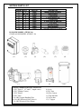
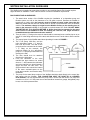
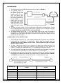
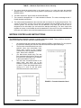
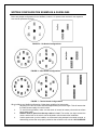
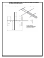
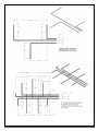
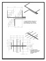
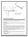
WetDek
INSTALLATION INSTRUCTIONS
AND OWNER’S MANUAL
CORPORATE HEADQUARTERS
WESTERN SALES AND MANUFACTURING PLANT
P.O. Box 400 ● 1017 SW Berg Parkway
Canby, Oregon 97013
(503) 266-2231 ● Fax (503) 266-4334
www.srsmith.com
06-901
© S.R. Smith LLC 2008
NOV07
INTRODUCTION
The WetDek is designed for use as a residential splash pad. Proper installation, use, and maintenance
are essential for optimal performance and to reduce the risk of accident or injury. These instructions are
developed and intended for use with either the stand alone or poolside versions of the WetDek with 6, 9,
or 12 nozzles.
**IMPORTANT**
Check entire box and inside all packing materials for parts. Before beginning assembly, read the
instructions and identify parts using the figures and parts listed in this document. It is critical that all
parts be carefully inspected by the installer prior to installation to ensure that no damage occurred in
transit and that a damaged part is not used. Proper installation cannot be overstressed, as improper
installation voids S.R. Smith’s warranty and may affect the safety of the user.
WARNINGS
This unit must be hardwired only to a supply circuit that is protected by a ground
fault circuit interrupter (GFCI). Such a GFCI is required by most building codes and should be
provided by the installer and must be tested before each use. Consult GFCI manufacturers’ instructions
for correct testing and operation. A bonding lug has been provided on the outside of the electrical control
box. The lug permits the connection of No. 8 AWG solid copper bonding conductor between the controller
and all other electrical equipment and exposed metal in the vicinity. ALL ELECTRICAL CONNECTIONS
MUST COMPLY WITH NATIONAL ELECTRIC CODE, AS WELL AS ANY APPLICABLE LOCAL
CODES. A LICENSED ELECTRICIAN MUST BE USED FOR ALL ELECTRICAL CONNECTIONS.
DANGER – RISK OF ELECTRICAL SHOCK. Install at least 5 feet (1.5m) away from all metal
surfaces. A WetDek may be installed within 5 feet of metal surfaces if each metal surface is permanently
connected by a minimum No. 8 AWG solid copper conductor; that is bonded to the control box. Do not
permit any electrical appliance such as a light, telephone, radio, or television within 5 feet (1.5m)
of a WetDek.
EXTREME CAUTION – adult supervision required during use. Do not leave
children unattended around the WetDek. To avoid accidents and injury, ensure that children
cannot use the Wetdek unless they are supervised by a responsible adult at all times. Do not use the
WetDek if the drain cover or nozzles are broken or malfunctioning in any way. A broken drain cover can
cause severe injury so examination of drain before each use is critical. Ensure before use that drain
cover is secured and that drain is functioning properly. Note: the WetDek is not intended to be a wading
pool of any sort, do not allow use if pooling or back up of water occurs.
CHEMICAL SAFETY – Play it safe with chemicals. Maintain sanitizer level of 3-5 ppm of
bromine or chlorine. There is risk of illness if the water is not properly sanitized. Follow all chemical
manufacturers’ recommendations to ensure proper sanitation. Always store chemicals according to the
manufacturer’s label directions and keep them out of reach of children. The stand alone model reservoir
should be emptied at least every two months.
WETDEK PARTS LIST
ITEM NO
1
2
3
4
5
6
7
8
9
10
QTY
1
6, 9, 12
4
3
1
1
1
1
1
1
PART NO
30000
31000
30005
30006
30007
30008
30001
30002
30003
30004
DESCRIPTION
WetDek System Controller
Brass Nozzles
1” HPV Valves
1” Valve Manifold Tee
1” Globe Valve
4” Nickel Drain w/ ABS Hub
¾ HP Pump
25sf Filter Housing
Inline Chlorinator
150 Gallon Reservoir w/ Fittings
POOLSIDE MODEL (ITEMS 1-6)
STAND ALONE MODEL (ITEMS 1-10)
(1)
(2)
(7)
(3)
(4)
(8)
ITEMS NEEDED FOR INSTALLATION
1) PVC Pipe (4”, 1.5” and 1”, length varies)
2) PVC Fittings (Varies)
3) PVC Primer
4) PVC Glue
5) 8 AWG Copper Bonding Wire
6) 16 AWG Electrical Wire (Valves)
7) 8 AWG Electrical Wire (Pump)
(5)
(9)
8) Level
9) PVC Saw
10) Wire Cutters
11) Tape Measure
12) Valve Box
13) 1” Spigot
(6)
(10)
WETDEK INSTALLATION GUIDELINES
The WetDek can be installed as a stand alone product or as a poolside feature. Each model requires
slight variations in installation. There is also a section of common installation requirements.
BACKYARD STAND ALONE MODEL
1. The stand alone version of the WetDek requires the installation of a dependent pump and
filtration system, as well as the placement of a 150 gallon reservoir. Because the WetDek is
based upon a gravity drain, the reservoir must be located at least 6 inches lower then the
drain; this means that the reservoir should either be buried or placed downhill from the WetDek
surface. The maximum change in height from the WetDek surface to the standing level of
water in the reservoir is 5 feet. If more height is required contact S.R. Smith. DO NOT HOOK
THE WETDEK UP TO A SUCTION RETURN. A Spigot should be incorporated in the stand
alone version of the WetDek to allow for draining the reservoir; this spigot should be
located between the chlorinator and valve manifold.
2. There is a third 1 ½” fitting on the reservoir that should be connected as an overflow pipe or as an
auto-fill. It is the fitting near the top of the tank, and should run to a French drain or other overflow
area.
3. The proper layout for the WetDek stand alone plumbing is located in FIGURE 1.
4. The ¾ HP pump, 25sf filter, and the
inline chlorinator require 1 ½” pipe for
both inlet and outlet. The inlet of the
pump should be connected to the lowest
1 ½” fitting on the reservoir; the
maximum height for the self-priming
pump is 7 ft. The pump outlet should run
directly to the filter
5. The filter should then be attached
directly to the chlorinator.
6. From the chlorinator to the valve
manifold the pipe needs to be scaled
down to 1”; also between the chlorinator
and valve manifold you should attach a
spigot and then the ball valve. The
spigot and ball valve should be located
FIGURE 1
in the same enclosed space as the
pump and controller, and must be easily
accessible.
7. The pump for the stand alone version of the WetDek should be wired directly to the control box
that comes with the WetDek. THIS CONNECTION MUST BE DONE BY A LICENSED
ELECTRICIAN. This will regulate when the pump runs in unison with the valves. The pump and
controller run off of a 115 Volt power source and should be located in a garage, designated pump
house, or a similar protected area.
POOLSIDE MODEL
1. The proper layout for the WetDek pool side plumbing is located in FIGURE 2.
2. The poolside version of
the WetDek will run off of
the same pump and
filtration system as the
pool. The existing pool
pump will need to provide
the following gallons per
minute (GPM): a six
nozzle model will require
8-12 GPM, a nine nozzle
model will require 12-16
GPM, and a twelve nozzle
FIGURE 2
model will require 16-24
GPM.
3. The drain must be a minimum of 6” above the surface of the water in the adjacent pool. This will
help to eliminate puddles from forming on the surface. The drain should run directly to the pool,
and MUST NEVER BE CONNECTED TO A SUCTION RETURN.
4. The WetDek should have its own 1 ½” or 2” pipe coming off of the pool pump. This should be
sized down to 1” pipe right before the valve manifold. The ball valve requires 1” pipe, and must be
placed before the valve manifold. No spigot is required for the poolside version because the pool
will have its own drain system.
COMMON INSTALLATION INSTRUCTIONS
1. The nozzles can be placed in any of the examples presented in the following section, WETDEK
CONFIGURATION EXAMPLES & GUIDELINES. Please note: all nozzles must be
approximately the same distance from the valves to assure that the height of the water
streams remains constant.
2. The slope of the surface needs to have a minimum two degree slope towards the drain. This
means that for every foot of radius there needs to be a quarter inch drop, e.g. 14 ft. diameter pad
means a 7 ft. radius, so the pad should drop 1 ¾ in. from the edge of the pad to the drain.
8. The nozzles must be at least two feet from the edge of the pad to prevent overspray. The nozzles
have adjustable ball valves that can be aimed in any direction, up to 60 degrees.
9. The distance from the pump to the valves and from the valves to the nozzles is important.
Depending on the distance, the diameter of pipe needs to vary for optimal performance. TABLE 1
and FIGURE 3, below, shows the size of pipe required for varying distances of pipe.
Distance (Ft)
Pump to Valves (Pipe Diameter in
Inches)
Valves to Nozzles (Pipe Diameter in
Inches)
50
1.5
1
100
1.5
Not Recommended
150
2
Not Recommended
200
2
Not Recommended
250
Not Recommended
Not Recommended
TABLE 1 – Maximum Pipe Distance due to Viscosity
5. The valves should be placed either in the pump house or in a valve box near the intended
WetDek surface. The valves can only be placed in a pump house if the pad is within 50 feet of the
WetDek surface.
6. The drain requires a 4” pipe to drain the surface efficiently.
7. The nozzles are designed with a 1” male threaded connection. The valves are designed with 1”
female threaded connections.
8. The valves should be attached to the control box with a minimum of 16 gauge electrical wire. The
valves are 24 Volt AC, so each valve needs to be attached with two separate wires; there is no
common ground. The first three valves can be attached in any order, but the fourth valve is
designed as the recirculation line and should be attached accordingly. The three valves that
regulate the zones on the WetDek should be attached off of the tee on the valve manifolds and
the fourth, recirculation, valve should be attached at the end of the valve manifold.
WETDEK CONTROLLER INSTRUCTIONS
The WetDek System Controller requires an onsite electrician to install. These guidelines should be
used to insure that the controller has been installed properly.
1.
2.
3.
4.
All wires that enter the controller should be placed in NEMA-1 rated fittings. For UL purposes
the electrician installing the controller must drill these holes and place the fittings.
The first wires connected should run to the
solenoid valves and recirculation lines.
These wires connect to the Fountain
Controller box, and are labeled as follows:
SOL1, SOL2, SOL3, RECIRC.
(For stand alone models only) The next
item connected should be the pump, and
this should be connected to the contactor
in the inputs labeled T1 and T2.
The last wires connected should be the
power wires, and these run to the
contactor as well but on the side labeled
L1 and L2. (There are already black wires
running to L1 and L2, but the power
should be wired next to these wires.)
FIGURE 3 – Fountain Controller Panel
FIGURE 4 – Controller Contactor
WETDEK CONFIGURATION EXAMPLES & GUIDELINES
Below are sample configurations for the WetDek; numbers 1-3 represent the nozzles for the respective
zone and D represents the drain.
FIGURE 5 – Six Nozzle Configurations
FIGURE 6 – Nine Nozzle Configurations
FIGURE 7 – Twelve Nozzle Configurations
When building your WetDek configuration, follow these guidelines for best results.
1.
All piping from valve to nozzle should be approximately the same length. This will ensure that
the water shoots equally from each nozzle.
2.
To avoid forming puddles, make sure that drain is located at lowest point and that surface
has a steady slope.
3.
Nozzles must be placed so that top surface is level. The surface can slope around the
nozzle, and the ball on the nozzle can be adjusted to aim the water after installation.
4.
Surface options are up to the installer; we recommend using stamped or brushed concrete, or
alternatively pavers that are properly sealed so that all water runs to drain. ANY SURFACE
USED WITH THE WETDEK MUST MEET ANY LOCAL OR NATIONAL CODES FOR NONSLIP SURFACES AND HEALTH SAFETY.
The following images show the pipe layouts for the nozzles for the various configurations given above.
WETDEK CARE & MAINTENANCE
There are a couple of areas of the WetDek that require regular maintenance: water, plumbing, and the
pump. Routine checks will help prolong the life of all components of the WetDek.
WATER TESTING
It is recommended that you test your WetDek water regularly with an accurate test kit or test strips. These
are available from your local Pool & Spa Dealer. Also, be sure to follow chemical manufacturer’s
instructions for chemical use.
pH CONTROL
All water solutions have pH, which is a measure of the acid to base relationship. A pH reading of 7.0 is
neutral, a lower reading is acidic and a higher reading is basic. The proper pH for WetDek water is
between 7.4 and 7.6 High pH (above 7.6) can reduce sanitizer efficiency, cloud the water, promote scale
formation on surfaces and equipment, and interfere with filter operations. When pH is too high, add a pH
decreaser. Low pH (below 7.2) is equally damaging and can cause equipment corrosion, water that is
irritating, and rapid sanitizer dissipation. Add pH increaser to bring the pH higher.
It is important to use scale and stain inhibitor weekly to prevent calcium deposits from damaging your
WetDek and equipment. If this happens, it could void the warranty. Refer to your chemical handbook for
further information on water chemistry and troubleshooting.
DRAINING THE WATER
Locate spigot between the chlorinator and valve manifold. Attach garden hose and open valve. The
controller should be set to recirculation during draining. Any water that the pump does not remove should
be sucked out with a wet/dry vacuum.
FILTER MAINTENANCE
At least once a four week, (or more often based on environmental conditions) check and clean the
skimmer basket of the pump to insure proper flow. Remove leaves, foreign matter and debris when
present. It is also very important to maintain your WetDek filter cartridge clean and free of particles that
can obstruct water flow. A clean filter will permit the system to function properly and also allows more
efficient filtering. Depending on how frequently your WetDek is used, we recommend cleaning the
WetDek filter cartridge every four to six weeks. If this is not done, the filter may clog and restrict water
flow, which causes inadequate filtration and poor nozzle performance.
CLEANING THE FILTER
Carefully pull up the filter cartridge and bring it out of the WetDek. Rinse cartridge using a garden hose.
Rotate and separate filter pleats while spraying water to remove all debris possible. Let the filter dry and
look for calcium deposits (scaling) or an oil film. If you find these, you will need to deep clean your filter
cartridge with a “spa filter cleaning” solution to break down and remove mineral deposits and oils.
WINTERIZATION
You must winterize the WetDek when freezing temperatures are expected or if prolonged periods without
use are expected; this will help protect all components. Water should be drained from the reservoir in the
stand alone model, and water should be cleared from the pump, filter, chlorinator, and all piping. The balls
in the nozzles should be rotated so that no water can drain into them and then tightened.
IMPORTANT
PERSONALLY GIVE TO OWNER THIS WETDEK OWNER’S MANUAL, THE
WARRANTY CARD AND ANSWER ALL QUESTIONS.