1
ScoopY+
Mono / Stereo portable audio codec
ISDN / POTS / MOBILE / IP
User Manual
Table of contents
1. Presentation y Getting started ................................................................ 1 1.1. Install and connect ScoopY+ ..................................................................................... 3 1.2. Audio settings ........................................................................................................... 3 1.3. Select and set up network to be used: wired networks .................................................... 3 1.3.1. Set up an ISDN link ................................................................................................. 3 1.3.2. Set up a (wired) IP link .............................................................................................. 4 1.3.3. Set up a POTS link................................................................................................... 4 1.4. Select and set up network to be used: mobile networks.................................................. 5 1.4.1. Set up a link in voice mode ....................................................................................... 5 1.4.2. Set up a (mobile) IP link............................................................................................ 5 2. Functions ............................................................................................ 6 2.1. Transmission interfaces .............................................................................................. 7 2.1.1. Ethernet/IP interface ................................................................................................. 7 2.1.2. ISDN interfaces ....................................................................................................... 9 2.1.3. POTS interface ...................................................................................................... 10 2.1.4. Mobile network access ........................................................................................... 11 2.1.5. Managing calls ..................................................................................................... 12 2.2. Audio encoding and decoding ................................................................................. 13 2.2.1. G711 coding ........................................................................................................ 14 2.2.2. Mobile telephony coding: GSM , AMR ..................................................................... 14 2.2.3. Mobile HD Voice coding: AMR-WB ......................................................................... 14 2.2.4. CELP coding ......................................................................................................... 14 2.2.5. G722 coding ........................................................................................................ 15 2.2.6. TDAC coding ........................................................................................................ 15 2.2.7. 4SB ADPCM coding............................................................................................... 15 2.2.8. MPEG Audio Layer 2 coding ................................................................................... 16 2.2.9. MPEG AAC algorithms ........................................................................................... 16 2.3. Audio interfaces ...................................................................................................... 17 2.3.1. Analogue inputs .................................................................................................... 17 2.3.2. Mixed Inputs ......................................................................................................... 18 2.3.3. Analogue Outputs ................................................................................................. 18 2.3.1. Audio monitoring .................................................................................................. 18 2.3.2. International sound ................................................................................................ 18 2.3.1. Coordination channel ............................................................................................ 19 2.3.1. USB interface ........................................................................................................ 19 2.3.1. Extension interface ................................................................................................. 19 2.3.1. Recorder .............................................................................................................. 19 2.3.2. Audio routing ........................................................................................................ 20 2.4. Auxiliary functions ................................................................................................... 24 2.4.1. Transmission of relays ............................................................................................ 25 2.4.2. Use isolated relays ................................................................................................. 25 2.4.3. Data channel ........................................................................................................ 25 2.4.4. Coordination channel ............................................................................................ 26 2.5. Supervision and control interface .............................................................................. 27 ´/RFDOµFRQWURO ...................................................................................................... 27 SCOOPY+ - User Manual
(PEHGGHGKWPOVHUYHU´ZHESDJHVµ ....................................................................... 27 2.5.3. Additional Ethernet/IP interface ............................................................................... 27 2.5.4. Configuration and dialling memories ...................................................................... 27 2.5.5. Test functions ....................................................................................................... 28 3. Operation .......................................................................................... 29 3.1. General principles ² Control means .......................................................................... 29 3.2. Physical description of the equipment ........................................................................ 30 3.2.1. Front panel .......................................................................................................... 30 3.2.2. Rear panel ........................................................................................................... 33 3.3. Installation and set up .............................................................................................. 35 3.3.1. Mounting and connections ..................................................................................... 35 3.3.2. Initial set up ......................................................................................................... 35 3.4. Initial setup of the Ethernet interface .......................................................................... 36 3.4.1. DHCP server available........................................................................................... 36 ´6WDWLFµ,3FRQILJXUDWLRQ ......................................................................................... 36 3.4.3. Checking the IP configuration................................................................................. 36 2SWLRQDOFRQILJXUDWLRQRIWKH´OLQNµ(WKHUQHWOD\HU .................................................... 37 3.4.5. Configuration of the secondary Ethernet interface ..................................................... 37 3.5. Managing links ....................................................................................................... 38 3.5.1. Setting up and releasing links ................................................................................. 38 3.5.2. Auto-redial feature ................................................................................................ 38 3.6. First level maintenance............................................................................................. 39 3.6.1. Using the test loops ............................................................................................... 39 4. Detailed operating mode y User interface .............................................. 40 4.1. Equipment start-up .................................................................................................. 40 4.2. Principles for the navigation ...................................................................................... 41 4.3. Dialing and text input keypad ................................................................................... 42 4.4. Description of the menus .......................................................................................... 43 4.4.1. Network sub-menu ............................................................................................... 44 4.4.2. Algorithm sub-menu .............................................................................................. 53 4.4.3. Audio sub-menu ................................................................................................... 54 4.4.4. Profiles
menu ............................................................................................. 56 4.4.5. Tools / About sub-menu ........................................................................................ 57 4.4.6. Misc sub-menu ...................................................................................................... 58 4.4.7. Maintenance sub-menu ......................................................................................... 60 4.5. Setting up a link ...................................................................................................... 61 4.5.1. Setting up a link in ISDN mode ............................................................................... 61 4.5.2. Setting up links in double ISDN codec mode ............................................................ 63 4.5.3. Setting up a link in IP mode via Ethernet .................................................................. 65 4.5.4. Setting up a POTS link ........................................................................................... 68 4.5.5. Setting up a mobile telephone link .......................................................................... 69 4.5.6. Setting up a link in IP mode via a mobile network ..................................................... 71 4.6. Management of the configuration profiles .................................................................. 74 4.7. Restricted operation mode ........................................................................................ 75 4.7.1. Principles ............................................................................................................. 75 4.7.2. Locking the front panel .......................................................................................... 75 4.7.3. Unlocking the front panel....................................................................................... 75 SCOOPY+ - User Manual
4.7.4. Lost the password? ................................................................................................ 76 4.8. Clearing all settings ................................................................................................ 77 4.9. Backing up and restoring the configuration ................................................................ 77 4.10. Displaying received SMS ........................................................................................ 77 4.11. Audio File (record) ................................................................................................ 78 4.11.1. Settings .............................................................................................................. 78 4.11.2. Record ............................................................................................................... 78 4.11.3. Play ................................................................................................................... 78 4.11.4. Edit .................................................................................................................... 79 5. Operating mode y Embedded HTML pages ............................................. 80 5.1. Accessing the SCOOPY+ html pages ....................................................................... 80 5.2. Principles of operation with html pages ...................................................................... 81 ´6WDWXVµWDE ............................................................................................................ 82 ´&RQQHFWLRQVµWDE .................................................................................................. 83 5.5. ´3URILOHVµWDE .......................................................................................................... 84 ´5HPRWHSURILOHVµSDJH .......................................................................................... 84 5.5.2. ´/RFDOSURILOHVµSDJH ............................................................................................. 84 5.5.3. Snapshots ............................................................................................................. 84 ´1HWZRUNµWDE ........................................................................................................ 85 ´&KDQJH1HWZRUNµSDJHGHIDXOWLQWHUIDFHVHOHFWLRQ .................................................. 85 ´(WKHUQHW3DUDPHWHUµSDJH ..................................................................................... 85 ´$R,33DUDPHWHUµSDJH .......................................................................................... 86 5.6.4. ISDN Parameter page ............................................................................................ 87 ´32763DUDPHWHUVµSDJH ....................................................................................... 87 ´0RELOH3DUDPHWHUµSDJH ....................................................................................... 88 5.7. ´$XGLRµWDE............................................................................................................ 89 ´&RGLQJµWDE ......................................................................................................... 91 5.9. ´0LVFµWDE.............................................................................................................. 92 ´0DLQWHQDQFHµWDE ................................................................................................ 93 ´/RJLQGDWDµSDJH ............................................................................................... 93 ´7HVWVµSDJH ....................................................................................................... 93 ´6\VWHPXSGDWHµSDJH .......................................................................................... 93 ´5HVHWµSDJH ....................................................................................................... 94 ´(YHQWORJµSDJH ................................................................................................. 95 ´6HWXS7UDQVIHUµSDJH .......................................................................................... 96 ´$ODUPµWDE .......................................................................................................... 97 6. Technical characteristics ..................................................................... 98 6.1. Characteristics of interfaces...................................................................................... 98 6.1.1. Analogue audio inputs ........................................................................................... 98 6.1.2. Analogue audio outputs ......................................................................................... 98 6.1.3. Headphone outputs ............................................................................................... 98 6.1.4. Ethernet Interface................................................................................................... 98 6.1.5. ISDN interfaces ..................................................................................................... 99 6.1.6. POTS/PSTN interface ............................................................................................. 99 6.1.7. Antenna socket (mobile networks) ............................................................................ 99 6.1.8. Batteries supply ..................................................................................................... 99 6.1.9. DC power supply ................................................................................................. 100 6.2. Audio performance ............................................................................................... 101 SCOOPY+ - User Manual
6.2.1. Transmission gain ............................................................................................... 101 6.2.2. Amplitude-frequency response .............................................................................. 101 6.2.3. Group delay distortion ......................................................................................... 101 6.2.4. Idle channel noise ............................................................................................... 101 6.2.5. Total distortion vs frequency and level ................................................................... 102 6.2.6. Crosstalk ........................................................................................................... 102 6.2.7. Gain and phase difference between channels......................................................... 102 6.3. Network protocols and ports ................................................................................... 103 6.4. Dimensions and weight .......................................................................................... 103 6.5. Environmental characteristics .................................................................................. 103 6.6. Options ............................................................................................................... 104 6.6.1. Network options ................................................................................................. 104 6.6.2. Other options ..................................................................................................... 104 6.7. Accessories and related products ............................................................................ 105 7. Annexes...........................................................................................107 7.1. Additional information on the algorithms and protocols used...................................... 107 7.1.1. Auxiliary data in the MPEG frames ........................................................................ 107 7.1.2. Reed-Solomon encoding...................................................................................... 107 7.1.3. H221 framing .................................................................................................... 107 7.2. Overview of the SIP protocol................................................................................... 108 7.2.1. What is SIP? ....................................................................................................... 108 7.2.2. Setting a link with SIP........................................................................................... 108 7.2.3. Setting a link without a SIP server .......................................................................... 109 7.3. Some methods to deal with NAT routers and firewalls ................................................ 110 7.3.1. Links via a private network ................................................................................... 110 7.3.2. Links through a public network (Internet) ................................................................ 110 7.3.3. Summary and reminder of essential rules ............................................................... 114 7.4. Notice regarding open source code ........................................................................ 115 8. Index ...............................................................................................116 Base on Scoopy+ Version 3.0
SCOOPY+ - User Manual
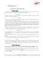
1. Presentation y Getting started
The SCOOPY+ codec allows the bi-directional transmission of one or two audio signals with bit rate
reduction, over various transmission media: ISDN lines, PSTN telephone lines, ,3SURWRFROQHWZRUNV«
The standard version of the codec includes an Ethernet interface for IP transmission. The unit can be
complemented with many options providing additional network interfaces, coding algorithms, etc.
One outstanding feature of AETA codecs in ISDN mode is the 5A System£: on receiving an incoming
ISDN call, the unit can automatically detect the coding algorithm and parameters of the calling
codec, and then adjust itself in a compatible configuration so that the connection succeeds regardless
of the initial configuration and that of the remote unit.
In IP mode, the codec features the same ease of operation thanks to the use of the SIP and SDP
protocols.
This chapter gives basic instructions for a quick start. It obviously does not provide all the information
for full control. For comprehensive information one can refer to the rest of this manual:
x Chapter 2 describes all the functions and features of the SCOOPY+ (but not necessarily with
all the operating modes)
x
x
x
x
x
Chapter 3 gives a physical description of the unit, shows its setting up and operation
principles.
Chapter 4 details menus and operating modes.
Chapter 4.11 deals with using the html server embedded in SCOOPY+
Chapter 6 provides all the technical characteristics of the SCOOPY+
The annexes bring miscellaneous additional information, including an index you can use to
look for a given information topic.
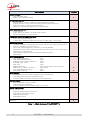
The following table shows the main features of the product. Functions marked with z in this table are
available as options.
£ 5AS = Aeta Audio Advanced Automatic Adjustment System
SCOOPY+ - User Manual
1
Characteristics
Optional
Operation modes
Single wide band codec
Double 7 kHz codec (ISDN mode)
z
IP transmission interface
Ethernet Interface, 10BaseT / 100BaseT; TCP/IP, UDP/IP, RTP protocols
Audio transmission in unicast mode: SIP signalling protocol, SDP, RTP streaming
Audio transmission in multicast mode: RTP streaming
Net bit rate 16 to 256 kbit/s (depending on coding algorithm)
ISDN transmission interface
z
One S0 interface
Single codec 64 or 128kbit/s , or double codec 64 kbit/s
5AS auto configuration on incoming calls
Transmission interface on PSTN telephone line
z
2QH´ZLUHµWHOHSKRQHLQWHUIDFH
« POTS codec » mode with integrated V34 modem and CELP coding, 12 to 24 kbit/s
Mobile network access
z
Integrated 2G/3G/3G+/LTE (depending on version) network access module with one internal
antenna ( 1 sockets for get out the antenna )
9RLFHPRGHVWDQGDUGWHOHSKRQHRU´+'9RLFHµ(7 kHz with AMR-WB)
Packet data mode: IP protocol, SIP signalling, SDP, RTP streaming, net bit rate 16 to 256 kbit/s
(depending on coding algorithm)
External 3G/LTE module connection via USB socket (data mode only)
SMS reception
Audio coding algorithms
G711 (standard telephone)
GSM, AMR (mobile telephone)
AMR-WB / G722.2 (PRELOH´+'9RLFHµ
G722 SRT, H221, H242
CELP 7 kHz
MPEG Audio Layer II
MPEG AAC-LC , HE-AAC, HE-AAC v2
4 sub-band ADPCM (low latency)
TDAC (ISDN mode only)
(audio modes)
Mono
Mono
Mono
Mono
Mono
Mono, Stereo, Double mono, Joint stereo
Mono, Stereo
Mono
Mono
z
z
Audio interfaces
3 analog MIC/line inputs and two analog outputs with adjustable gain
Level display for encoder inputs and decoder outputs
2 stereo headphone sockets for monitoring, balanced send/receive
Auxiliary functions (available depending on transmission interface)
Relay management : 2 keys and 2 LEDs
Data channel 300 to 9600 bauds
Audio coordination channel with Mobile option ( up to 7kHz )
Control and supervision
Keyboard and LCD display on front panel
Programmable set-up/dial memories
Ethernet/IP remote control
Embedded html server
Recording
z
Table 1 ² Main features of the SCOOPY+
2
SCOOPY+ - User Manual
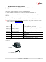
1.1. Install and connect ScoopY+
x
Plug on a power source or put 6 C batteries.
x
Turn SCOOPY + on by holding
for >3 seconds. (Hold down
turn it off!)
Connect the necessary audio interfaces (details: page 17)
x
x
x
for > 3 seconds to
Connect ScoopY+ on the transmission network (details: page 33 and following)
Using the ScoopY+ menus:
key or
key to activate the main menu, use the joystick to
select a sub-menu or a parameter, enter or validate with the
key.
jumps back up to
the previous menu level, until getting back to the base screen (with level display).
(details: page 41)
1.2. Audio settings
x
With factory settings, all inputs are routed to the main program, and clipping level is set at
+12 dBu for both inputs and outputs.
x
Enter the menus using
further on page 54.
, select Setup then Audio. Perform necessary settings, see details
1.3. Select and set up network to be used: wired networks
x
Select network: Setup menu then Network, then select Change Network,
. In the
proposed choice, select the desired network (ISDN, MOBILE, Ethernet, POTS). Validate
with
.
x
Select the audio coding: menu Setup / Algorithm, then Other, then
. Browse the
available choice with the arrows, and make a selection with
. Restart the same procedure
to change for another coding setup.
L The available choice depends on the transmission network! For more details on coding,
see page 13.
1.3.1. Set up an ISDN link
x
If needed, select the protocol with Setup / Network / ISDN Parameter / Protocol. More
details: see page 48.
x
x
Enter the remote number to dial, using the keypad, and press the
x
Hang up with the
key.
If more than one B channel is involved due to the coding algorithm used, you must enter a
second number, then
, and so on. If the last dialled number is adequate, just confirm by
pressing
without typing a number again.
key to release the connection (you must confirm by pressing
SCOOPY+ - User Manual
again).
3
1.3.2. Set up a (wired) IP link
Over a public IP network, and especially when no SIP server is used, it is highly
recommended to use a STUN server.
The address of a STUN server can be set in the SCOOPY+ html pages (see page 86) or via the
menu: Setup / Network / AoIP Parameter / STUN Server, enter the address of a STUN server
(we propose our server stun.aeta-audio.com, look also the support pages on our web site
www.aeta-audio.com). Enable or disable STUN with Setup / Network / AoIP Parameter /
STUN Mode (On or Off).
More details: see page 111.
x
Check the Ethernet interface is active thanks to the LED on the Ethernet socket on the back,
and check an IP address is allocated: menu Tools / About / Local IP.
x
The default setting uses a DHCP server to get an IP address, which is suitable for most
occasions. In other situations, look for more details on page 36.
x
Using the keypad, enter the remote number to call (numeric IP address, or SIP URI if a SIP
server is used), then press the
key.
x
x
Hang up with the
key (you must confirm by pressing
again).
When using a SIP server, some data must be entered beforehand using the AoIP Parameter menu; for more details, refer to page 46.
1.3.3. Set up a POTS link
x
x
For connecting the line, you must plug the POTS line in ANALOG socket.
x
x
Enter the remote number to dial, using the keypad, and press the
If needed, adjust the POTS line parameters using Setup / Network / POTS Parameter.
Details on these settings: see page 49.
Hang up with the
4
key.
key to release the connection (you must confirm by pressing
SCOOPY+ - User Manual
again).
1.4. Select and set up network to be used: mobile networks
To set links over a mobile network, you must have a SIM card with a subscription suitable for the use.
Specifically, for an IP mode transmission the subscription must include access to data transmission,
and RTP audio streams must be allowed.
x
While the unit is switched off, insert the SIM card into the drawer on the rear side of the
SCOOPY+.
x
x
Switch on the SCOOPY+ (depress
a few seconds).
Enter the menu Setup / Network / Other (Network) / Mobile (Int.) / Mobile Parameter / PIN. Enter the PIN code for the SIM card using the keypad then
.
1.4.1. Set up a link in voice mode
This mode allows communicating with any telephone terminal through the regular telephone service. It
also allows to benefit from the 7 N+]ZLGHEDQGVHUYLFHNQRZQDV´+'9RLFHµZKHQHYHUWKHUHPRWH
terminal is compatible and the network supports the service.
x
x
In the menu Setup / Network / Mobile Parameter, select Mode / Cellphone
x
The Network Select menu enables you to select among the available operators, if your
mobile subscription entiltes you to do so.
x
Enter the remote number to dial, using the keypad, and press the
x
Hang up with the
Afterwards, go to the menu Setup / Network / Mobile Parameter / Network Settings /
Preferred Technology / Auto
key.
key to release the connection (you must confirm by pressing
again).
1.4.2. Set up a (mobile) IP link
Over a public IP network, and especially when no SIP server is used, it is highly
recommended to use a STUN server.
The address of a STUN server can be set in the SCOOPY+ html pages (see page 86) or via the
menu: Setup / Network / AoIP Parameter / STUN Server, enter the address of a STUN server
(we propose our server stun.aeta-audio.com, look also the support pages on our web site
www.aeta-audio.com). Enable or disable STUN with Setup / Network / AoIP Parameter /
STUN Mode (On or Off).
More details: see page 111.
x
x
In the menu Setup / Network / Mobile Parameter, select Mode / IP Mode
x
Go to the menu PS Settings / APN: HQWHUWKHRSHUDWRU·VAPN code, using the keypad, then
press
.
x
x
Come back to the base screen using the
x
x
Hang up with the
Come back to the menu Setup / Network / Mobile Parameter / Network Settings /
Preferred Technology / Auto
key.
Using the keypad, enter the remote number to call (numeric IP address, or SIP URI if a SIP
server is used), then press the
key.
key (you must confirm by pressing
again).
When using a SIP server, some data must be entered beforehand using the AoIP Parameter menu; for more details, refer to page 46.
SCOOPY+ - User Manual
5
2. Functions
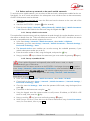
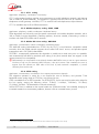
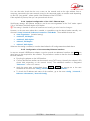
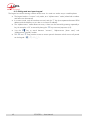
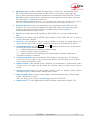
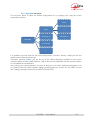
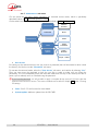
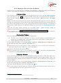
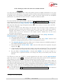
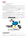
The following synoptic diagram shows the basic functions of the equipment.
Figure 1 ² Functional diagram of the equipment
The audio signals to be transmitted are converted (when needed) to digital format, then the encoding
function reduces the bit rate, using a selectable algorithm; the resulting bit flow is sent to one of the
available transmission interfaces: Ethernet interface, ISDN interface, PSTN interface, mobile network...
The transmission interface functional block also extracts compressed data coming from the network
and sends them to a decoding block that reproduces uncompressed audio data. Last, the audio
signals are output to analogue outputs.
Monitoring the audio interfaces is possible thanks to headphones and level meters for the
inputs/outputs.
In addition to the main task of transmitting an audio programme, the SCOOPY+ can also transmit
auxiliary information, usually by embedding them inside the transmitted audio streams.
Supervision and controlling the unit is performed using various remote control interfaces, and of
course by means of the displays and controls on the front panel.
6
SCOOPY+ - User Manual
2.1. Transmission interfaces
The SCOOPY+ features in all versions an Ethernet interface for IP protocol networks.
One ISDN, PSTN/POTS and mobile network access is optionally available.
2.1.1. Ethernet/IP interface
The IP interface is a 10BaseT/100BaseT Ethernet interface allowing transmission of the audio
programmes in a wide range of possible bit rates. The audio stream is always transported under the
RTP/UDP protocol.
IP unicast mode
The most classical transmission mode is unicast: audio connection with one distant device, generally
bidirectional. This mode can be used on all types of networks links, LAN or WAN, including links via
Internet. The SCOOPY+ implements the SIP protocol, which allows it to interoperate with IP phones
and other SIP compatible audio codecs, in a way similar to ISDN or POTS connections. Links can be
set up in two ways:
x
x
´3HHUWRSHHUµFRQQHFWLRQEHWZHHQWZRFRPSDWLEOHXQLWV
Use of a SIP proxy server to set up the link, or a SIP PBX
Details about the SIP protocols can be found in the annex (see 7.2, Overview of the SIP protocol).
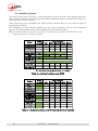
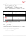
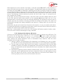
The audio coding algorithm can be selected depending on the required quality and the available
network bandwidth. The following algorithms are currently available:
Codec
Bit rate
(coding)
Bit rate
(total)1
Audio
bandwidth
Typical use, main features
G711
64 kbit/s
86 kbit/s
3 kHz
Voice, telephony
Compatible with IP phones
CELP
24 kbit/s
28,5 kbit/s
7 kHz
Suitable for high quality speech;
Low network bandwidth consumption
G722
64 kbit/s
86 kbit/s
7 kHz
High quality speech.
Compatible with some IP phones.
MPEG Layer II
64 to 256
kbit/s
73 to 275
kbit/s
Up to
20 kHz
Highest quality, suitable for speech and
music
MPEG AAC-LC
16 to 256
kbit/s
30 to 277
kbit/s
Up to
20 kHz
Low bit rate, suitable for speech and
music
MPEG HE-AAC
and HE-AAC v2
16 to 128
kbit/s
23 to 139
kbit/s
Up to
20 kHz
Very low bit rate, suitable for speech and
music
4SB ADPCM
128 or
256 kbit/s
173 or
301 kbit/s
15 kHz
Low latency, suitable for speech and
music
Table 2 ² Overview of algorithms available in IP mode
1 InIRUPDWLYHYDOXHKLJKHUWKDQWKH´QHWµHQFRGHGDXGLRELWUDWHEHFDXVHRIWKHSURWRFRORYHUKHDG
SCOOPY+ - User Manual
7
SIP and SDP protocols
The SIP protocol is a signalling protocol, used for IP connections, which allows the SCOOPY+ to
interoperate with IP phones and other SIP compatible audio codecs, in a way similar to ISDN or POTS
connections. Details about the SIP protocols can be found in the annex (refer to 7.2, Overview of the
SIP protocol).
One significant advantage is the inclusion of SDP, a protocol which allows the connecting devices to
automatically negotiate and agree on the coding profile to use. Thanks to this system, it is not
necessary to set the units in the same way before setting up a connection. Moreover, the calling party
needs not know how the remote unit is configured before initiating a link.
L Note: the SIP protocol does not mandatorily imply the use of a server. Codecs can set up point-topoint links using this protocol, and benefit from some its advantages.
Packet replication
SCOOPY+ also proposes an RTP transmission mode with enhanced reliability, using packet
replication. When enabling this mode, every packet is transmitted twice; with such system a lost packet
has no effect since the receiver still gets the other copy of the packet. In this way, stable links can be
obtained even with a high packet loss rate. Of course, as a disadvantage the bit rate is double; you
must make sure this stays compatible with the transmission medium.
Remote control via IP
In addition, the Ethernet interface can be used for configuring or remote controlling the unit, with two
control methods:
x
SCOOPY+ provides html pages which allow to get complete control over the unit using a
web browser, via port 80 (default port for http protocol). See in chapter 4.11 the detailed
operating mode.
x
TCP port 6000 can be used for ´command lineµ control, suitable for codec supervision
software such as Codec Live, MDC.net, etc.
8
SCOOPY+ - User Manual
2.1.2. ISDN interfaces
For access to the ISDN, the transmission interface is one S0 BRI (Basic Rate Interface), for transmission
over one to two 64 kbit/s B channels.
The codec synchronises itself onto the ISDN network clock when a link is active.
Network protocols
Available protocols:
x
´Euro ISDNµ (or ETSI), default protocol valid for a large number of countries, especially all
over Europe.
x
´NTTµ valid for the Japanese network of NTT
x
´NI-1µ: valid for numerous operators in North America. This choice is also suitable for the
connection to network equipment with ´NI-1µ ´1,-µ protocol.
L In North America (USA and Canada), the available interface is often a U0 interface (instead of
S0). ,Q VXFK FDVH DQ ´17µ QHWZRUN DGDSWHU PXVW EH LQVHUWHG EHWZHHQ WKH OLQH DQG WKH
SCOOPY+. Such adapter can be found on the local market.
5A System®
Setting an ISDN connection is often difficult, at least because of the numerous coding parameters to
be set. Moreover, with most proprietary algorithms, it is mandatory for the two devices to have exactly
the same settings, otherwise the connection will fail, and sometimes it is not easy to find out the
reason.
5A stands for Aeta Audio Advanced Automatic Adjustment. This system makes it easier to set an ISDN
connection, because the codec, on receiving a call, automatically adjusts itself, following the calling
party algorithm and parameters.
When the 5A System is enabled on the unit and a call is received, the unit first detects the coding
algorithm used by the calling codec, and also senses its parameters: audio PRGH PRQRVWHUHR« sampling rate, bit rate, inverse multiplexing protocol, etc. Then the unit can decode the compressed
audio from the remote unit. In addition, the unit will use these same settings for encoding and sending
audio to the remote unit, so that the remote unit can also decode the outgoing audio programme.
The whole process just takes a few seconds. Of course, all compatible coding configurations can be
detected automatically by the 5A System.
Note that the 5A system is only active for ISDN connections.
J52
The ITU-T J52 recommendation was defined in order to allow the interoperability of multimedia
terminals over the ISDN1, using common coding standards. It includes the following features:
x
x
Support of ITU-T recommended coding algorithms: G711, G722, MPEG Layer II
x
x
Interoperation procedures according to ITU-T H242 recommendation;
Framing as per ITU-T H221 recommendation, ensuring byte synchronisation and
interchannel synchronisation when more than one 64 kbit/s B channel is required for the
desired bit rate;
In the case of MPEG encoding, optional protection against transmission errors (ReedSolomon error correction codes).
Details about MPEG and J52 can be found in the annexes (refer to 7.1, Additional information on the
algorithms and protocols used).
1 J52 is only relevant for ISDN connections
SCOOPY+ - User Manual
9
It must be noted that, thanks to the interoperation protocol, J52 codecs, when setting up a link, can
negotiate automatically and agree on a configuration that is compatible with the capability of both
units (regarding bit rate, channel mode, etc.). In this way, when the units differ in their capability (or
make), the resulting configuration may be different from expected beforehand, but in most cases the
link will work and audio will be transmitted.
As another useful consequence, this also gives users more tolerance to mistakes when configuring the
units on the two sides of the transmission links, as the codecs will adapt automatically even with
differences in the initial settings of the two units.
Symmetric or asymmetric coding
In most operating cases, the codec sets up symmetrical links, wherein the encoder and decoder use
the same encoding/decoding algorithm with same settings (channel mode, etc.). In other words, the
OLQNLV´IXOO-GXSOH[µDQGWKHVDPHHQFRGLQJGHFRGLQJW\SHLVXVHGRQERWKGLUHFWLRQV
For a link over the ISDN, in fact there are cases when the link is asymmetric, with a different coding
mode in each direction. This may happen in some cases with the J52 protocol. To give some
examples, it is possible to send MPEG Layer II in one direction and receive G722 in the reverse
direction, or send MPEG stereo and receive MPEG mono, etc.
2.1.3. POTS interface
7KHLQWHUIDFHLVD´WZRZLUHµDQDORJWHOHSKRQHDFFHVVZLWKFKDUDFWHULVWLFVDGMXVWDEOHGHSHQGLQJRQ
the country. Dialling normally uses DTMF, but for older switching equipment it is possible to use pulse
dialling.
SCOOPY+ includes a V34 modem which transmits via this line a bidirectional audio flow, encoded at
a nominal 24 kbit/s bit rate. Depending on the line quality and the quality of the link with the remote
codec, this bit rate is automatically negotiated and dynamically adjusted from 12 to 24 kbit/s.
$´SURWHFWHG´PRGHFDQEHDFtivated, which increases the resilience to transmission errors, at the cost
of a higher latency (encoder to decoder delay). You must make sure to set this parameter the same
way on both devices / both ends of the link.
10
SCOOPY+ - User Manual
2.1.4. Mobile network access
Units equipped with the ´Wirelessµ option include an integrated module for access to 2G/3G/3G+
mobile networks, and a holder for a SIM card.
Depending on the version the accessible networks are 2G (GSM, EDGE), 3G (UMTS), 3G+ (HSDPA,
+683$+3$« and 4G/LTE.
The SCOOPY+ include one or two internal antennas ( 4G/LTE module only). If an external antenna is
necessary, you can connect one multiband antenna (to be selected for compliance with the mobile
network characteristics) on SCOOPY+.
Lastly, SCOOPY+ can display the received SMS messages.
Mobile voice mode ² HD Voice
The integrated module allows using the mobile phone service, for communicating with all ISDN or
PSTN telephone terminals or hybrids, or with other mobile terminals. The quality is in such case that of
mobile connections, with a 300-3400 Hz bandwidth and coding such as GSM, EFR, AMR...
1RZPDQ\PRELOHQHWZRUNVDOVRSURSRVH´+'9RLFHµDQH[WHQVLRQRIWKLVPRELOHWHOHSKRQHVHUYLFH
With this new capability, compatible terminals implement the AMR-WB coding algorithm (standardised
as G722.2 by the ITU-T) and provide speech transmission with a 50-7000 Hz bandwidth and a
quality very similar to the well-known G722. Automatic fallback to the standard coding takes place if
the network does not support the service or one of the terminals does not feature this capability.
No special subscription, other than to the regular telephone service, is needed, but for most operators
only the 3G/3G+ base stations support the service.
L This sometimes makes people believe that HD Voice is related to the mobile IP service, but this is
definitely not the case.
More and more mobile phones now support this service, especially (but not only, and not all)
smartphones. $OO$(7$FRGHFVLQ´:LUHOHVVµYHUVLRQVXpport HD Voice, namely:
x
x
x
SCOOP 4+ LQ´wirelessµYHUVLRQ
SCOOP 5+ LQ´wirelessµYHUVLRQ
ScoopFone HD
SCOOPY+ - User Manual
11
Mobile IP mode
The other service available with mobile access is the data packet transmission mode, abbreviated as
´36µ IRU3DFNHW6ZLWFKHG ZLWK,3SUotocol.
This mode brings similar capabilities as a wired IP connection via the Ethernet interface, as described
above in 2.1.1, with some distinctive characteristics:
x
This requires a subscription including access to the data service, with conditions compliant
with the application. Among other requirements, an APN (Access Point Name) must be
provided that allows this type of media stream.
x
The available bit rate depends on various factors; first the network technology
(***« , EXWDOVRWKHWUDIILFOHYHOLQWKHUDGLRFHOOWKHRSHUDWRU·VQHWZRUNFDSDFLW\
possibly the type of subscription. This may bring on restrictions for the usable compression
algorithms.
x
x
The multicast mode is not available on mobile networks
Setting a link implies first activating the data connection, before actually initiating an audio
stream transmission link
Using an external USB module
Instead of the integrated module, it is possible to plug a USB PRELOH PRGXOH RU ´NH\µ LQ RUGHU WR
access mobile IP transmission, with more or less similar conditions as described above.
L However be aware:
x
x
x
x
This capability is optional
The USB module must be from the list of devices supported by AETA. As this list is evolving,
please check our web site for up to date information.
7KH´+'9RLFHµPRGHLVQRWDYDLODEOHLQWKLVZD\
USB devices do not feature antenna diversity
2.1.5. Managing calls
One of the transmission interfaces is selected as the default interface on the SCOOPY+.
A call towards a remote unit, initiated by the user of the SCOOPY+, is implicitly sent through this
default interface.
On the other hand, an incoming call on any interface (regardless of the default interface) can be
processed and the link established, under following conditions:
x
The ´calledµ interface must be connected and active. As an example, for mobile IP the data
connection must be active.
x The codec must not be already busy with another connection.
If the call comes on an interface other than the default interface, the codec first switches to the
suitable interface, and then processes the incoming call. When the link is released, it will come back
to its previous state (and default interface).
12
SCOOPY+ - User Manual
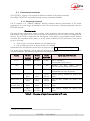
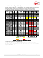
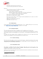
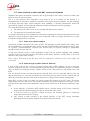
2.2. Audio encoding and decoding
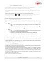
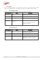
SCOOPY+ features a wide range of coding algorithms. Their availability depends on the transmission
network used. Besides, the MPEG family algorithms feature a large configuration flexibility.
The table below synthetically describes the capabilities with the various transmission media:
Codec
G 711
G SM, AMR
AMR- W B
CE LP
CE LP
G 722
G722-H221
G722-H242
TDAC
4SB ADP CM
4SB ADP CM
MP E G L2
MP E G L2
MP E G L2
MP E G L2
MP E G L2
AAC- LC
AAC- LC
AAC- LC
AAC- LC
AAC- LC
AAC- LC
HE - AAC
HE - AAC
HE - AAC
HE - AAC
HE - AAC v 2
HE - AAC v 2
F requency ( kHz)
Audio
channels 16 24 32 48
Mono
Mono
Mono
Mono
Mono
Mono
Mono
Mono
Mono
Mono
Stéréo
M / S
M / S
M / S
Stereo
Stereo
M / S
M / S
M / S
M / S
M / S
Stereo
M / S
M / S
Stereo
Stereo
Stereo
Stereo
Bit rate
( kbit/s)
W ired
P STN
ISDN
64
12 o 22.8
24
64
64
64
64
128
256
64
128
192
256
384
16 o 56
64
96
128
192
256
16 o 56
64
96
128
16 o 56
64
Mobile
3G +
E thernet
LTE
UMTS
Voice
[ 2]
[ 2]
IP networks
P ossible audio bandwidth:
3 kHz
7 kHz
15 kHz
20 kHz
Table 3 ² Available coding depending on network
This table applies to the normal mode, single codec.
In double codec ISDN mode, only G711 and G722 algorithms are available for each codec.
The following chapters bring some precisions about the important features of the various algorithms
and protocols available.
SCOOPY+ - User Manual
13
2.2.1. G711 coding
Application: telephony, coordination. Low latency.
G711 is the standard coding used for voice transmission on public telephone networks, and features
300 to 3400 Hz audio bandwidth. This algorithm is typically used for links over IP networks with IP
telephones or VoIP gateways. Via ISDN, G711 is used for links with telephones or hybrid devices.
G711 is available only for IP or ISDN transmission
2.2.2. Mobile telephony coding: GSM , AMR
Application: telephony, mobile coordination. Moderate latency.
These algorithms are exclusively used for speech transmission over mobile telephone networks, with a
300 to 3400 Hz audio bandwidth. Gateways perform, whenever needed, transcoding in order to
interface with fixed PSTN, ISDN and IP networks.
2.2.3. Mobile HD Voice coding: AMR-WB
Application: commentaries, mobile coordination. Moderate latency.
The AMR-WB coding (standardised as G722.2 by the ITU-T) is used between compatible mobile
terminalsZKHQWKHPRELOHQHWZRUNVXSSRUWVWKHVRFDOOHG´+'9RLFHµVHUYLFHDQGSURYLGHVVSHHFK
transmission with a 50-7000 Hz bandwidth.
SCOOPY+ automatically implements this algorithm in mobile voice mode every time it is possible,
and automatically falls back to standard voice coding if not (when network does not support, or the
remote terminal is not compatible).
L Unfortunately it is not possible to see directly whether AMR-WB is active or not at a given moment.
You have to rely on your listening skills! However, it has to be active if the conditions are met: a)
support from the network on both sides of the link, b) both terminals compatible, c) service
continuity from end to end1
2.2.4. CELP coding
Application: commentaries, coordination. Low capacity transmission channels
This algorithm operates in mono for a net nominal bit rate of 24 kbit/s, and provides 7 kHz
bandwidth and a quality close to G722 for a much lower bit rate.
CELP is available for IP or PSTN networks. For PSTN (POTS), the bit rate may be reduced to adapt for
the line quality, among the following values: 12 kbit/s, 14.4 kbit/s, 16.8 kbit/s, 19.2 kbit/s,
21.6 kbit/s, 24 kbit/s. The bandwidth is reduced accordingly.
6WLOOIRU3276OLQHVLQDGGLWLRQWRWKHQRUPDOPRGHWZR´SURWHFWHGPRGHVµDUHDYDLODEOHbringing an
increased resistance to transmission problems, however with an increased latency as well.
1 At the time of writing, this requires both units to be on the same network: same operator, same country
14
SCOOPY+ - User Manual
2.2.5. G722 coding
Application: commentaries, coordination. Low latency.
This mono coding algorithm at a 64 kbit/s bit rate is a reference for commentaries, and features a
50-7000 Hz bandwidth.
It is available, ISDN, IP networks (wired or mobile).
For ISDN, three synchronisation modes are possible:
x
x
x
´6WDWLVWLFDOUHFRYHU\µE\WHV\QFKURQLVDWLRQPHWKRG DOLDV657);
H221 synchronisation; in this case, 1.6 kbit/s from the compressed data are used for this;
H221 synchronisation and H242 protocol.
H221 synchronisation is highly recommended when possible, as it features higher reliability and faster
recovery time, while degradation (because of the bit rate used for framing) is minimal.
H242 protocol, the most flexible mode, is recommended by the ITU-T, and is included in J52.
However, the mode with H221 synchronisation but without H242 protocol can be useful for
compatibility with old generation codecs which did not use this protocol.
No specific synchronisation is required for the IP mode.
2.2.6. TDAC coding
Application: commentaries, mono music via ISDN with only one B channel.
The SCOOPY+ can also include the TDAC algorithm. TDAC is for Time Domain Aliasing
Cancellation; this is a transform coding based on an MDCT (Modified Discrete Cosine Transform),
encoding a 15 kHz bandwidth mono signal at a 64 kbit/s bit rate.
TDAC is available as an option, only for the ISDN mode.
2.2.7. 4SB ADPCM coding
Application: commentaries, mono or stereo music. Low latency.
4SB ADPCM operates either in mono at a 128 kbit/s rate, or in stereo at 256 kbit/s, for a 15 kHz
bandwidth. It features a very low latency which makes it very interesting for live duplex transmission. It
also has the advantage to be very little sensitive to tandem coding.
4SB ADPCM is available for ISDN ( Mono only ); wired or mobile IP. However it is not recommended
for mobile networks, because it requires a high bit rate and it is highly sensitive to packet losses, which
can be frequent on such networks.
SCOOPY+ - User Manual
15
2.2.8. MPEG Audio Layer 2 coding
Application: mono or stereo music, high quality.
As shown on Table 3, this coding algorithm features a maximum flexibility, with many variations for bit
rate, mono or stereo channel mode, sampling rates...
The two channel modes exist in three variations:
x
x
Stereo: coding of each channel stays independent
Dual mono: coding is similar to the previous case, but this choice applies to channel with no
acoustic relationship, e.g. two languages for commentaries
x
Joint stereo: applies to stereo programme, but here the encoder exploits the interchannel
correlation for improved coding. To be used only for a stereo programme
The 16 and 24 kHz sampling rates feature a moderate bandwidth (respectively 7 kHz and 10 kHz)
and are rather useful for commentaries.
L The latency is rather high with these sampling rates
MPEG L2 is available for LL, ISDN; wired or mobile IP networks.
ISDN mode specific aspects: J52
For ISDN transmission, MPEG L2 is proposed with two variations:
x
´MPEG L2 J52µ variation, using the ITU-T J52 protocol for the link negotiation and inverse
multiplexing (B channel aggregation for connections requiring more than 64 kbit/s).
Moreover, optional protection against transmission errors (FEC) is also available. For more
details refer to 2.1.2, ISDN interfaces (page 9).
x
MPEG L2µ variation, without the J52 protocol, using a system for inverse multiplexing two B
channels which is proprietary but compatible with several codecs on the market. The bit rate is
limited to 128 kbit/s with this option.
2.2.9. MPEG AAC algorithms
Application: mono or stereo music, Low capacity transmission channels.
These (optional) algorithms feature a very high compression ratio, for a given audio quality,
compared to Layer 2. They can operate at a sampling rate of 32 or 48 kHz, and several bit rates: 16,
20, 24, 32, 40, 48, 56, 64, 96, 128, 192, 256 kbit/s ( 192 & 256kbit/s only in IP mode ). Three
coding variations are available:
x
MPEG AAC-LC (´Low Complexityµ): lower compression than other variations, but lower
latency.
x
MPEG HE-AAC ´High Efficiencyµ$$& : higher compression, and the bit rate is limited to
128 kbit/s for this variation.
x
MPEG HE-AAC v2 ´+LJK(IILFLHQF\µ$$&YHUVLRQ : compared to the above, this coding
further enhances the performance for a stereo program (not available for mono). The bit rate
is limited to 128 kbit/s for this variation.
AAC codecs are available as an option for ISDN, and wired or mobile IP networks.
16
SCOOPY+ - User Manual
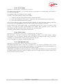
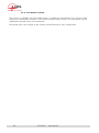
2.3. Audio interfaces
Figure 2 ² Left panel
Figure 3 ² Right panel
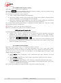
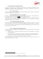
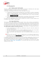
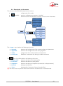
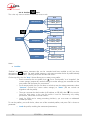
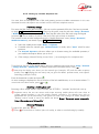
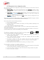
2.3.1. Analogue inputs
Scoopy+ contains an audio mixer, that enables three microphones to be mixed. The third microphone
inputs accept line level via adjustable PAD, when the source is either a recorder of a mixing console. If
you need more microphone inputs, you can use AETA AUDIO SYSTEMS mixer : MIXY on the extension
port. Mixy will add 3 more microphones inputs plus many lines inputs. Mixy is automatically detected
by the scoopy+.
Dyn/Ph./T12*
0..48dB
Fader 80dB
OFF/HP
Lim/Comp
Input 1
Lim/Comp
Input 2
A/N
Lim/Comp
Input 3
Audio
compression
24 bits 48KHz
PAD
0/-20dB
Mbm
Mute
Mbm
Mbm
Mbm
Mbm : managed by menu
Figure 4 Mixer features
The following elements are available for each mic/line input:
- Input connector: female XLR;
SCOOPY+ - User Manual
17
-
Pad switch to adjust the gain on each input
A mute activation pad located on the front panel
By menu 1
- Gain pad (to adjust by step of 16 dB from 0 to 48dB).
- Microphone power selection switches
None: dynamic microphone or line live
Phantom: phantom power supply (48V or 12V switch configuration)
7´7RQDGGHUµ 9 IRUFHUWDLQVWDWLFPLFURSKRnes
- Each input has a high pass filter @ 50Hz, 18db/oct.
- Each input has a limiter preset at -8dBFs.
- Each input can be routed on main program or/and coordination line in mono or on left or
right channel of stereo codec.
- Default mute configuration on power on
- PAD 20dB on the input 3 only
2.3.2. Mixed Inputs
On the Mixed signal, you have a level adjustment from -12 to +12dB by 1dB step. You can set it by
menu Setup / Audio / Input / Global Gain. By default it is set to 0dB.
2.3.3. Analogue Outputs
The mixed audio signal from inputs is available on the 2 headphones and 2 output lines.
Local audio from the inputs can be mixed with the return audio signal on each headphone. The return
audio signal is present in the headphone mix via the Local / Cue Mix Balance potentiometer on the
front.
By default, the return program audio is assigned to the output lines. You can assign local audio
program or the headphone 2 mixed audio signals to the output by menu.
2.3.1. Audio monitoring
The levels on the bar graph on the front panel of the Scoopy+ indicate the peak level of the mixed
audio signal. The level displayed is registered at the analog-digital converter overloading level. The
¶UHIHUHQFH·OHYHl can be fixed by the audio menu.
2.3.2. International sound
This feature is available only with mono transmission. Each Input can be set by menu as an
international sound input. Then this mode is enabled, selected inputs can be sending on the
headphone right channel in place of return signal.
Warning: You FDQ·W have at the same time an international sound and coordination channel, because
both use the same mixer channel.
1 See Audio menu
18
SCOOPY+ - User Manual
2.3.1. Coordination channel
With Mobile option, you can have access to a coordination channel over Mobile network. Through
menu you can assign inputs to this channel. Also, you can enable a monitoring of the coordination
channel return on each headphone.
With the DYNAMIC mode, as the way of orders is not connected, the headphones still have only the
program. This is when the channel order is established that the switching is done according to the
choice of headphone
2.3.1. USB interface
Scoopy+ has also the capability to establish a link with a PC or a MAC. The Scoopy+ is seeing as a
stereo sound card by the computer. Depending of the Scoopy+ configuration, you can record on the
computer the main program (send signal on the left and return signal on the right)
On the other way, audio play on the computer is mixed with ScoopY+ inputs. See 2.3.2 for more
details.
2.3.1. Extension interface
Scoopy+ has also the capability to establish a link with the small AETA 3 channels mixer ( Mixy ) .
Scoopy+ mixes the Mixy signal with its own inputs. Like that, you can increase your configuration up
to 6 microphones.
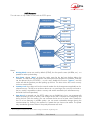
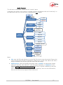
2.3.1. Recorder
Scoopy+ can record on an SDCARD in mono or stereo the mix of inputs. See next chapter ´Audio
routingµ and ´Audio menuµ for the configuration
WARNING: When you enable the coordination channel, the recorder records the main program and
the coordination return channel when you select a stereo audio file. This configuration is perfect to
record a remote interview.
SCOOPY+ - User Manual
19
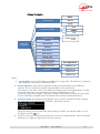
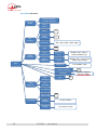
2.3.2. Audio routing
20
SCOOPY+ - User Manual
SCOOPY+ - User Manual
21
22
SCOOPY+ - User Manual
SCOOPY+ - User Manual
23
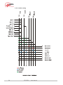
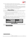
2.4. Auxiliary functions
The main function of the SCOOPY+ is the transmission of one or two main audio programmes, but it
also provides auxiliary functions for transmitting data or additional signals, inside the same stream (or,
more generally, the same session).
These features are only compatible with AETA products, because they are not inside the scope of
independent standards.
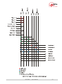
The availability of these functions depends on the coding algorithms, and on the transmission
network. The following tables show these capabilities for the various networks.
L No auxiliary function is available for mobile voice transmission. Besides, for PSTN/POTS only
´UHOD\WUDQVPLVVLRQµ 4 loops) is possible.
Codec
G 711
CE LP
G 722- SRT
G 722- H221
G 722- H242
TDAC
4SB ADP CM
MP E G L2
MP E G L2/J52
AAC- LC
HE - AAC
HE - AAC v 2
Relays
Isolated
300
Data ( bauds)
1200 2400 4800
X
X
X
X
9600
X = exclusiv e ( only one function at a time)
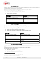
Table 4 ² Auxiliary functions: over ISDN
Codec
Relays
Isolated
300
Data ( bauds)
1200 2400 4800
9600
G 711
CE LP
G 722
G 722- H221
G 722- H242
TDAC
4SB ADP CM
MP E G L2
MP E G L2/J52
AAC- LC
HE - AAC
HE - AAC v 2
Table 5 ² Auxiliary functions: over IP networks (wired or mobile)
24
SCOOPY+ - User Manual
2.4.1. Transmission of relays
You can transmit 2 states (Contacts) through a data channel during an establish link.
7KHVHFRQWDFWVFDQPDQJHUHOD\RU´21$,5µ/DPSRQWKHUHPRWHVLGH
1RWH,Q,6'1 3276WKHIHDWXUHVKRXOGEHHQDEOHGRQERWKVLGHV6RPHDOJRULWKPVGRQ·WVXSSRUW
it in ISDN.
Enter the menu by pressing OK, set Tools / Misc / Aux. Functions/ Relays to ON.
During the connection, with
and
you can change the state of the remote relays. From the
main window, you can see the state of them by pressing the joystick to the right.
LED Info 1 and 2 VKRZ\RXWKHVWDWHRIWKHUHPRWHFRQWDFWVLHORFDO´UHOD\Vµ
2.4.2. Use isolated relays
To access this feature, you should connect an external USB relay box on your Scoopy+ (Contact your
dealer for the compatibly).When this function is activated, you can set feature for each of them.
x
x
Inputs
o Info 1/2: the codec transmits to the remote unit the status of the isolated current
loops.
o
Redial: Redial the last phone number with the same configuration (same as twice
o
Release : Hang-up the call (same as
)
)
Relays
o Info 1 / 2: the remote codec transmits its input state. The unit then opens or closes
relay contacts according to the transmitted status.
o Line state: The unit closes relay contacts when the connection is established
o Sync. State: The unit closes relay contacts when audio are decoding correctly
For transmission over IP, this feature is always available whatever the coding algorithm. For the other
networks, availability depends on the algorithm: see above tables.
With G722 or 4SB ADPCM, relay transmission cannot be used at the same time as another auxiliary
function (see tables).
A typical application is the transmission of ´on airµ signals; a contact closure can be used for instance
to light up an indicator or switch on other equipment.
2.4.3. Data channel
This function is available in ISDN transmission mode.
In ISDN mode, a bi-directional data channel can be transmitted along with the compressed audio
signals, by reserving a fraction of the transmitted bit rate.
The data are transparently transmitted end-to-end; hardware signalling is not available. Availability
depends on the coding algorithm, as well as the max possible baud rate: see above tables. With
G722 or 4SB ADPCM, this data channel cannot be used at the same time as another auxiliary
function (see tables).
On Scoopy+, the data channel is only used for remote control with AARC protocol from the data
channel interface of the remote codec.
Note : contact your distributor for more details
SCOOPY+ - User Manual
25
2.4.4. Coordination channel
This function is available only with Mobile option. It enables the transmission of an auxiliary audio
channel (or coordination channel) in voice mode through mobile network. This transmission can be
established in parallel of any over transmission.
Each audio input can be assign on this auxiliary channel through its menu configuration.
26
SCOOPY+ - User Manual
2.5. Supervision and control interface
The control and supervision of the equipment (configuration, communication management, status
PRQLWRULQJ LV FDUULHG RXW HLWKHU ´ORFDOO\µ WKDQNV WR D NH\ERDUG DQ DOSKDQXPHULF GLVSOD\ /('
indicators, or using various remote control interfaces.
2.5.1. v/RFDOwFRQWURO
For local management, the front panel includes a large keypad, a graphic OLED, and various LED
indicators for essential status information.
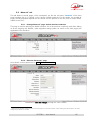
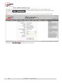
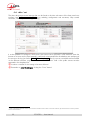
2.5.2. Embedded html server: vZeb pagesw
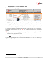
SCOOPY+ provides html pages that enable full control using a web browser, via port 80 (default port
for the HTTP protocol). See on chapter 4.11 the detailed operation mode.
This control mode can be used from any computer regardless of its OS (or a mobile device with a
web browser), and the embedded pages are compatible with all current browsers. No software
installation is needed on the control device.
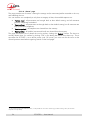
2.5.3. Additional Ethernet/IP interface
It is possible to get a second Ethernet/IP interface by plugging a USB/Ethernet adapter1 on the USB
socket. This interface can be used as a remote control port (html pages via port 80, RU ´FRPPDQG
OLQHµPRGHYLDSRUW DVDQDOWHUQDWLYe to the normal integrated interface. It should not be used
for other functions (audio over IP).
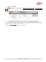
2.5.4. Configuration and dialling memories
To ease the operation, it is possLEOHWRVWRUHFRQILJXUDWLRQPHPRULHVFDOOHG´SURILOHVµ7KHVHEHORQJ
to three categories:
x
´Remote profilesµ, including the parameters for calling a given destination: dial numbers,
coding algorithm, etc.
x
´/RFDOSURILOHVµZKLFKPHPRULVHWKH network access characteristics. Recalling a local profile is
a quick way to recover the configuration needed for connecting on a given line/network.
x
´6QDSVKRWVµZKLFKPHPRULVHDOOWKHVHWWLQJVIRUWKHDXGLRLQWHUIDFHV
These various profiles can be used locally and also through the web pages, and they can be
imported/exported from/to a computer.
1 Reference : Logilink UA0144, or other device shown on our web site support pages.
SCOOPY+ - User Manual
27
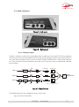
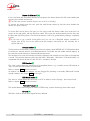
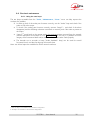
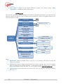
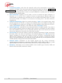
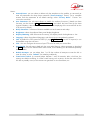
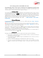
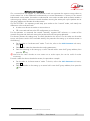
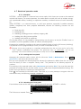
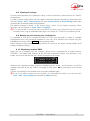
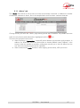
2.5.5. Test functions
For maintenance purposes, some test loops can be activated. The following drawing schematically
shows these test loops:
Figure 5 ² Test loops
x
´$XGLR ORRSµ XQFRPSUHVVHG DXGLR GDWD DUH ORRSHG IURP WKH LQSXW RI WKH HQFRGHU WR WKH
input of the output conversion functional block. This loop redirects the audio input to the
audio outputs;
x
´/RRS µ RU ´&RGHFµ ORRS FRPSUHVVHG DXGLR GDWD DUH ORRSHG MXVW EHIRUH WKH QHWZRUN
interface;
x
/RRSµRU´1HWZRUNµORRSWKLVORRSVHQGVWKHUHFHLYHGGDWDEDFNWRWKHQHWZRUN; for the
remote codec, the effect is the same as a loop 3 when the transmission works correctly;
x
´$XGLRIHHGEDFNµORRS DXGLRRXWSXWWRDXGLRLQSXW WKLVDOORZVWKHFRGHFWRVHQGEDFNWR
the remote codec the signal it receives, after decoding and re-encoding.
28
SCOOPY+ - User Manual
3. Operation
3.1. General principles y Control means
The equipment control and supervision (configuration, status monitoring) is possible either in ´/RFDOµ
mode (front panel keypad and display, status indicators), or ´5HPRWH FRQWUROµ PRGH WKDQNV WR DQ
Ethernet interface.
As a general rule, the configuration parameters are saved in non-volatile memory, and restored when
the unit is powered on.
Local mode operation is described in detail in chapter 4 (Detailed operating mode).
Remote control operation using a computer and a web browser, thanks to the embedded HTML
server, is detailed in chapter
.
The SCOOPY+ can be remote controlled by third-party codec management software and systems.
Please consult us for more information on the available offer in this field.
SCOOPY+ - User Manual
29
3.2. Physical description of the equipment
The SCOOPY+ codec is housed in an ABS chassis.
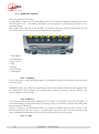
3.2.1. Front panel
All the elements needed for local controls are located on the front panel (see picture on page 31
below). This panel can be roughly divided in many parts:
One can find several LED indicators, an LCD and the main navigation keys. Another part can find
dialling keys and call management keys. Lastly, one can find audio control elements.
On/Off switch and standby
First, on the left is located the
on/off key, and just besides the ON indicator, keep the key
pressed for at least 3 seconds to switch on the unit. When it is operating, keep the key pressed for at
least 3 seconds to switch it off.
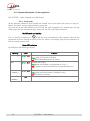
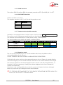
Status LED indicators
The LEDs have the following meaning:
Marking
Color
Function
DC/Charge
Green/Red Off when unit is RIIDQGKDVQ·W'&SRZHU;
Green when a DC power is pluged;
Red when internal batteries are in charge
DEC
Green/Red Off when unit is idle;
Green when the decoder is synchronised on ´Line 1µ;
Red if interface is active/connected but not synchronised or in
error
LIM
( 3 times )
Green/Red Off when limiter on associated input is off;
Green when the limiter feature is enable by menu;
Red if the limiter is working
ON
( 3times )
30
Red
On when Microphone input is enable and routed
SCOOPY+ - User Manual
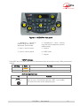
Figure 6 ² SCOOPY+ front panel
1 - Headphone 1 : Local/Cue
(external ring) and volume
adjustment (central knob)
2 - Input 1 volume control
4 - Headphone 2 : Local / external
ring) and volume adjustment (central
potentiometer)
5 ² Joystick
3 ² Input 2 volume control
6- OLED Screen
7 ² keypad
´INFOµ indicators
These LEDs show the state of the received information when the auxiliary function ´Relay transmissionµ
is active:
Marking
Color
Function
INFO 1
Amber
Shows the state of the ´relay contactµ n°1
INFO 2
Amber
Shows the state of the ´relay contactµ n°2
Audio management keys
Key
One ´Muteµkey for
each input
Function
Mute the input, ON led shows the state ( RED : input enable )
The initial mute state can be defined by menu
SCOOPY+ - User Manual
31
LCD and navigation keys
Besides the backlit graphic LCD one can find the keys for navigating through the menus:
Key
Function
OK
Confirm a selection or enter data.
From the base screen: switch to the root menu.
Esc
Escape to upper menu level;
From the base screen: switch to the root menu.
Navigation key :
Joystick
Keys used to move the cursor or browse through menu options.
The can be used to enter a sub-menu (like the OK key).
When entering data/numbers, the erases the character on the left
of the cursor.
A Confirmation ( Same as Ok key ) is available on the Joystick
Call management and dialling keys
Key
Function
´Hang upµ
Release an established link.
(except LL links, permanent by nature)
´Unhookµ
Start a link or accept an incoming call.
(except LL links, permanent by nature)
Dialling keys
0 .. 9
*.
#
Keys for entering numbers or URI for the destination to call. These
keys are also used to enter texts such as profile names, etc.
Repeatedly press a key to get the characters other than the main
figure.
Keys 1 and ´*.µ also allow entering special additional characters
(not all marked on the keypad).
The ´#µ key is used for switching between numbers, lower case
letters or capital letters. An indicator on the screen recalls the current
type of characters.
Figure 7 Recording keyboard
Function keys
The assignment of these F1 and F2 keys is programmable.
32
SCOOPY+ - User Manual
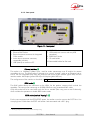
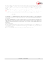
3.2.2. Rear panel
Figure 8 ² Rear panel
1. External DC 2.1mm Jack
2. Ethernet RJ45 Socket
3. External antenna connector for Integrated
GSM module
4. Audio device extension connector,
compatible with Mixy
5. USB (Mini-B) to connect to PC
6. POTS RJ11 Jack
7. USB interface to connect with any USB
peripheral
8. ISDN RJ45 Socket
9. SD card holder
10. Removable holder for SIM card
Ethernet interface [2]
This socket is a 100BaseT/10BaseT port, used for audio transmission over IP and/or for remote
controlling tKHXQLW7KLV5-VRFNHWLVGHYLVHGIRUDQRUPDO´VWUDLJKWµFDEOHWRDQ(WKHUQHWKXERU
switch. The two integrated LEDs show the presence and activity of the network (green LED) and the
interface mode: half-duplex (yellow LED off) or full-duplex (yellow LED on).
The configuration of the interface is described in 3.4, Initial setup of the Ethernet interface.
ISDN socket[8]
This RJ45 socket allows the connection to the ISDN, for the product versions which include this
capability. The wiring is for connecting an S0 (BRI) ISDN line using a standard RJ45 cable.
Only this socket has to be used when only one line is needed (links using one or two B channels),
which includes the operation in double ISDN codec mode.
POTS socket (marked ´$QDORJµ) [6]
For the units equipped with the PSTN/POTS option, this socket is used to connect the POTS line. You
must plug here a cable from the POTS wall socket1 and terminated with a RJ11 plug.
1 Whose type depends on the country and the building wiring
SCOOPY+ - User Manual
33
Drawer for SIM card [10]
In the units fitted with the mobile network access option, this drawer houses the SIM card enabling the
access to the network and services.
L The SIM card must be inserted while the unit is off (or in standby).
To remove the drawer and the card, push the small button shown by the little arrow besides the
drawer (see picture below).
To set the SIM card in place, first insert it in the cavity inside the drawer. Make sure to have the cut
corner on the right place, with the SIM chip visible. Then insert the whole assembly into the slot, with
the SIM card chip facing down. Check that the drawer is well in its guides before pushing it completely
in place.
L If you have to use a smaller format µSIM card, you can use a SIM/µSIM adapter (available on
request from AETA): first set the µSIM inside this adapter, afterwards use this assembly like a
regular SIM card.
Antenna sockets [3]
On the products fitted with the mobile network access option, these HIROSE MS-151NB sockets allow
to connect an external antenna (a multiband antenna is included with the mobile network option). In
this case the internal antenna is automatically disconnected.
The antennas must cover the band(s) used for the operator and network services. Refer to the operator
in doubt. The provided antenna covers the 900 MHz, 1800 MHz, 1900 MHz, 2100 MHz bands. It is
compatible with almost all the 2G and 3G/3G+ networks in Europe.
USB A socket [7]
This ´KRVWµ socket allows the connection of a peripheral device, e.g. a mobile access USB module or
´NH\µLQRUGHUWRDFFHVVPRELOH,3WUDQVPLVVLRQ
Refer to chapter 2.1.4 about this function.
As another use, an Ethernet adapter can be plugged for providing a secondary Ethernet/IP remote
control interface; see chapter 2.5.3 for this topic.
USB Mini-B socket [5]
This ´GHYLFHµ socket allows the connection to a PC in order to use the Scoopy+ has a sound card.
Refer to chapter 2.1.4 about this function.
´Extensionµ socket [4]
This socket allows connecting AETA AUDIO SYTEMS Mixy product for having more audio inputs.
SD card [9]
SDCard is used to record mixed signal for later diffusion.
34
SCOOPY+ - User Manual
3.3. Installation and set up
3.3.1. Mounting and connections
To operate the codec, the minimum necessary connections to set up are (see details in the rear panel
description):
x
x
x
Power supply (Batteries and/or DC);
Audio inputs and outputs (XLR sockets);
Network interface: depending on the networks used, Ethernet interface, ISDN line(s), POTS
line, or antenna(s) for mobile network access1;
The pin out of the connectors is indicated in chapter 6.1: Characteristics of interfaces.
3.3.2. Initial set up
Before the first use, the equipment must be configured according to the desired operation mode:
DXGLRLQSXWRXWSXWIRUPDWORFDOFRQGLWLRQV QHWZRUNLQWHUIDFHSDUDPHWHUV« Then to set up links you
must select the coding type and parameters.
For using the configuration menus, a password may have to be entered. After factory setting or after a
FRPSOHWHFRQILJXUDWLRQHUDVXUHWKHSDVVZRUGLV´EODQNµ QRSDVVZRUG DQGWKHDFFHss is unrestricted.
Afterwards, if needed, a password can be programmed by the user and the restricted access mode
can be activated.
For more details about the codec configuration, see chapter 4 - Detailed operating mode. The setup
for the Ethernet interface is described in 3.4 below (Initial setup of the Ethernet interface).
1 In such case, a SIM card should be set as well in order to enable the mobile services.
SCOOPY+ - User Manual
35
3.4. Initial setup of the Ethernet interface
The SCOOPY+ includes a 100BaseT / 10BaseT Ethernet interface, and the audio transmission can
take place over an IP network through this interface. In addition, it is always possible to use the
Ethernet interface to access the embedded html server or for remote control the unit via a TCP/IP
connection (TCP port 6000).
An initial set up is needed for using one of these features of the Ethernet interface. For setting into
operation, first connect the Ethernet interface to the network, using CAT5 wiring.
x
Connection to 10BaseT or 100BaseT interfaces are both suitable, as the SCOOPY+
automatically switches to the adequate 10 Mbit/s or 100 Mbit/s mode.
x
´6WUDLJKWIRUZDUGµ SDWFK FDEOHV VKRXOG EH XVHG IRU D FRQQHFWLRQ WR D KXE RU D VZLWFK
&RQYHUVHO\ D ´FURVVHGµ FDEOH PLJKW EH QHHGHd for special configurations (e.g. a test
connection to a PC).
As a very first step, the Ethernet interface must be assigned an IP address, and related parameters.
This phase is very simple when a DHCP server is available in the network. The menu to use is reached
by Setup / Network / Ethernet Parameter.
3.4.1. DHCP server available
This is the simplest case, because the server will allocate a suitable IP address and give the unit the
ULJKW VHWWLQJV 6HOHFW ´DHCPµ LQ WKHPHQX Setup / Network / Ethernet Parameter / Mode). The
unit will then automatically find the DHCP server and automatically set the parameters. You can read
WKH,3DGGUHVV DOORFDWHGWRWKHXQLWE\WKH'+&3VHUYHU LQWKH´$ERXWµPHQX Tools / About).
Note that, as an additional advantage with DHCP, you do not need to change this setting later, even
if you move the codec to another network, as long as it is still connected to a DHCP server.
3.4.2. v6WDWLFw,3FRQILJXUDWLRQ
When there is no DHCP server, you have to enter the settings manually. The IP address must be
´DYDLODEOHµ LH QRW DOUHDG\ DVVLJQHG WR RWKHU HTXLSPHQW Ask support from the network
administrator(s) as needed.
First select the manual mode, menu Setup / Network / Ethernet Parameter / Mode / Manual.
Then, still in the menu Setup / Network / Ethernet Parameter, you must enter the following
parameters:
Parameter
Notes
Local IP Must be unique on the network
Subnet Mask A typical value is 255.255.255.0
Gateway DNS Server 1 Domain Name Server (main)
DNS Server 2 Domain Name Server (secondary)
All addresses are in ´GRW-GHFLPDOµ format, such as e.g.: 192.168.0.12, 10.0.54.123.
L 1RWHLQFRQWUDVWWRWKHFRQILJXUDWLRQZLWK'+&3WKH´VWDWLFµVHWWLQJKDVWREHUHYLHZHGHDFKtime
you move the unit to a new physical site/network, as the previous IP addressing is probably not
valid for the new location.
3.4.3. Checking the IP configuration
7KHDERYHFRQILJXUDWLRQLVNHSWLQWKHXQLW·VPHPRU\DQGUHORDGHGDWHDFKVWDUW
7RFKHFNWKHVHWWLQJ\RXFDQUHDGWKH,3DGGUHVVLQWKH´$ERXWµPHQX Tools / About / Local IP).
36
SCOOPY+ - User Manual
You can then also check that the unit is seen on the network and at the right address: from a
computer connected to the same network, enter (in the command mode, or console mode depending
RQWKH26 ´SLQJipaddrµZKHUHipaddr is the IP address of the SCOOPY+.
If the response is positive, then you can proceed with the rest.
3.4.4. Optional configuration of the vlinkw Ethernet layer
:LWK IDFWRU\ VHWWLQJVWKH(WKHUQHW LQWHUIDFH LV VHW IRU DQ DXWR QHJRWLDWLRQ RI WKH µOLQNµ PRGH speed
(10 or 100 Mbit/s) and half-duplex or full-duplex.
L This setting LVVXLWDEOHIRUDOPRVWDOOVLWXDWLRQVDQGXVXDOO\\RXGRQ·WQHHGWRFKDQJHLW
However, in the rare cases where this is needed, it is possible to set the desired mode manually: use
the menu Setup / Network / Ethernet Parameter / Link Mode . The available choices are:
x
x
x
x
x
Auto-negotiation (standard setting)
100BaseT, full-duplex 100BaseT, half-duplex 10BaseT, full-duplex 10BaseT, half-duplex Whenever this setting is needed, it must be done before the IP configuration described above.
3.4.5. Configuration of the secondary Ethernet interface
In case an external USB/Ethernet adapter is used to provide an additional interface (see 2.5.3), an
initial setup is also required for this interface. The procedure is similar to that for the main integrated
Ethernet interface:
x
x
First plug the adapter on the USB Interface.
x
Apply the same steps as described above (3.4.1 to 3.4.4), the settings are in this case
accessed via the sub-menu Config / Network / Ethernet 1 Parameter.
x
To check the IP address and status of the interface, go to the menu Config / Network /
Ethernet 1 Parameter / Network Config.
Connect the Ethernet interface to the network, using CAT5 wiring. 1RUPDOO\WKHDGDSWHU·V/('
should blink depending on the network activity. The additional interface is designated
´Ethernet 1µLQWKHXQLW·VPHQXV
SCOOPY+ - User Manual
37
3.5. Managing links
3.5.1. Setting up and releasing links
Generally speaking, once the codec is set up and the transmission interface(s) to be used is(are)
configured, it is possible to manage audio links with remote devices.
A transmission links/sessions have to be set, which can be done in two ways:
x
´Outgoing callµ launched towards a remote device: the procedure is to select a transmission
LQWHUIDFH D FRGLQJ FRQILJXUDWLRQ ´GLDOµ WKH GHVWLQDWLRQ WR FDOO DQG WKHQ VHW the call to the
remote unit. The detailed operating mode is described further, for the various transmission
media, in 4.5 (Setting up a link).
x
´,QFRPLQJFDOOµUHFHLYHGIURPDUHPRWHGHYLFHRQUHFHLYLQJDFDOORQRQHRIWKHFRQQHFWHG
and active interfaces, the codec switches to this interface and processes the call.
In a similar way, ending/releasing a link is either initiated by the remote unit (remote release), or by
the operator of the SCOOPY+ (local release).
3.5.2. Auto-redial feature
TKH,3PRGHDQGWKH,6'1PRGHVDUH´GLDOXSPRGHVµZKHUHDOLQNFDQEHVHWXSDQGUHOHDVHGDt
will. When it is necessary to hold the link on permanently, outgoing calls may be backed up by using
the auto-redial function (for each codec in the double ISDN mode). When it is active and the codec is
the initiator of the link, the codec automatically tries to re-set the link in case of an initial failure, or if
an established link is dropped for another reason than a local release (i.e. hanging up by the user).
The redial capability applies in the following situations:
x
If the initial call fails for any reason (e.g. called party is busy); the codec then redials and
retries to establish the link.
x
The codec can also redial if the link is already established and the link is lost, for any reason
HOVHWKDQ´ORFDOUHOHDVHµ HJWKHUHPRWe unit mistakenly dropped the line).
x
After a power failure, after rebooting the codec will automatically redial and set-up the link
back.
L 1RWHWKDWZKLOH´DXWRUHGLDOµLVDFWLYHDQHVWDEOLVKHGOLQNFDQEHGHILQLWLYHO\VWRSSHGRQO\E\
releasing the line on the calling codec side. Otherwise, every time the called party will hang
up, the calling codec will redial and reset the link.
It is possible to program the time period that the unit will wait before redialling after a failed trial, and
it is also possible to program the maximum number of times the codec will redial before giving up.
7KH DFWLYDWLRQ RI WKLV IXQFWLRQ DQG WKH FRQILJXUDWLRQ RI LWV SDUDPHWHUV FDQ EH IRXQG LQ WKH ´$XWR
5HGLDOµVXE-menu (Tools / Misc / Auto Redial ). In dual codec mode, the function can be activated
separately for each codec.
38
SCOOPY+ - User Manual
3.6. First level maintenance
3.6.1. Using the test loops
The test loops DFFHVVLEOH IURP WKH ´Tools / Maintenance / Tests µ PHQX FDQ KHOS LPSURYH WKH
analysis of a problem:
x
In order to check if the aXGLRSDUWIXQFWLRQVFRUUHFWO\XVHWKH´$XGLRµORRSDQGFKHFNLIWKH
audio is OK at the output.
x
7R FKHFN LI WKH FRGLQJ SDUW IXQFWLRQV FRUUHFWO\ DFWLYDWH ´/RRS µ 1 and check if the alarm
disappears (and the decoding indicators come back to normal), and if the audio is present at
the output.
x
´/RRS µ2 sends back to the remote codec the compressed data received from the network
(see the description of test loops in 2.5.5, Test functions). In this way, it is possible to test the
integrity of the transmitted data and/or check that the remote codec works properly.
x
7KH GHFRGHU RXW WR HQFRGHU LQ ORRS ´$XGLR IHHGEDFNµ ORRS FDQ EH XVHG IRU RYHUDOO
functional check, and also for aligning the overall chain.
Note: not all test loops are available for all the network interfaces.
1 Note: this loop is not available for all transmission configurations
2 This loop is not available for all transmission configurations
SCOOPY+ - User Manual
39
4. Detailed operating mode y User interface
In local mode, the unit is operated thanks to a keypad and display on the front panel. The display is
an OLED graphic display.
Operating from the keyboard can be protected by a password (numeric sequence, that can be
SURJUDPPHG RU HUDVHG E\ WKH XVHU ,Q VXFK FDVH WKH RSHUDWLRQ LV LQ D ´UHVWULFWHGµ PRGH ZLWKRXW
direct access to settings or dialling. Only the profiles menu is accessible, for loading a profile or call a
remote profile (see later in 4.7, Restricted operation mode for more about the restricted mode).
4.1. Equipment start-up
Press the
key for at least 3 seconds to start up the unit.
During start-up, the unit displays temporary messages. This initialisation lasts around 30 seconds.
Then the main menu is displayed.
Network
interface
Current
coding
On this ´base screenµ, transmission and reception audio levels are permanently monitored for the two
audio channels.
At this time, the unit can be operated and receive calls. It is also possible, using the menus, to change
settings and/or set up calls.
L ,I WKH XQLW KDV EHHQ VHW LQ ´UHVWULFWHG DFFHVVµ PRGH IRU UHFRYHULQJ Iull access to all menus type
directly the password (numeric sequence), and the device unlocks as soon as the last figure of the
password is pressed.
See further in 4.7 how to use and manage this restricted access.
40
SCOOPY+ - User Manual
4.2. Principles for the navigation
From the base screen, if pressing the
µURRWPHQXµ1.
key the display switches to the highest level menu, called
Network interface
Current
coding
Pressing
again brings back the base screen.
The LED indicators and the main keys surrounding the LCD are described above in 3.2.1, Front panel
The unit proposes a tree structure of menus, and the Joystick is used to navigate through the menus.
The
key or the Joystick contact is used to confirm choices or enter values for parameter, while the
key allows to come back up to the upper menu level. Repeatedly pressing this key brings you up
to the root menu, and the base screen.
From the root menu, you can enter one of the three main menus by using the arrows and pressing
to enter the highlighted menu.
From these main menus, the screen is organized in the following way:
Menu
reminder
The sub-menus have the following aspect:
At the end of a ´branchµOLVWVRIFKRLFHVDSSHDULQWKLVZD\
Reminder of
parameter to set
In all cases, the principles are as follows:
x
Use the Joystick to browse sub-menus or choices.
x
x
Enter the highlighted sub-menu by pressing
x
x
Validate a choice or entered value using
Move to upper level with the
key or the
Give up a selection or action by pressing
or the key.
key
(repeatedly as needed)
L After some time without pressing any key (about 30 seconds), the display comes back to the base
screen.
1 You can also press the
key
SCOOPY+ - User Manual
41
4.3. Dialing and text input keypad
The keypad is used for entering numbers and/or texts. It is used in a similar way to a mobile phone:
x
The keypad wRUNVLQ´QXPHULFµRQO\PRGHRULQ´DOSKDQXPHULFµPRGH ZKHUHERWKQXPEHUV
and letters can be entered).
x
,QQXPHULFPRGHRQO\WKHQXPEHUVDUHXVHGDQGWKH´*µNH\ DVDVHSDUDWLRQEHWZHHQ,6'1
address and sub-address, or as a dot in a numeric IP address).
x
7KH´DOSKDQXPHULFµPRGHallows text entry. A letter can be entered by pressing repeatedly a
NH\IRUH[DPSOHD´%µLVHQWHUHGE\KLWWLQJWKH´2µNH\two times (sequence A, B).
x
Use the # key to switch between ´QXPHULFµ ´DOSKDQXPHULF (lower case µ DQG
´DOSKDQXPHULF capital µPRGHV
x
7KH´0µand ´1µkeys provide access to various special characters which are not all printed
on the keypad: ´@µ, ´:µ, ´-´´_µ«
42
SCOOPY+ - User Manual
4.4. Description of the menus
The root menu shows the following three main menus:
x
x
x
configuration of the codec
Setup
(profiles):
Tools
access to configuration memories or ´profilesµ
Maintenance and miscellaneous functions, access to status information
Network
Setup
Algorithm
Audio
Coord_line
Remote Prof.
[Root]
Local Prof.
Prof.
Snapshots
Records
Takes
About
Tools
Misc
Maintenance
The « Setup » menu leads to the following sub-menus:
x
x
x
x
The
Network
selection and configuration of the network interface and parameters
Algorithm
selection and configuration of the coding algorithm
Audio
configuration of the audio interface and parameters
Coord_Line Establish a coordination line through a mobile connection
menu for profiles leads to the following sub-menus:
x
x
x
x
x
Remote Prof.
selection and edition of remote profiles
Local Prof.
selection and edition of local profiles
Snapshots
selection and edition of snapshots (memories for audio parameters)
Records Manage recorded files
Takes Manage takes ( extraction of part of recorded files)
L This menu is the only branch of the menu tree that is accessible even in restricted mode.
SCOOPY+ - User Manual
43
The « Tools » menu is itself divided in sub-menus:
x
x
x
About
display information on addressing and firmware version
Misc
miscellaneous functions
Maintenance
maintenance and test functions
The following diagrams show the various sub-menus and the available parameters.
4.4.1. Network sub-menu
Change Network
Ethernet Parameters
AoIP Parameters
Network
ISDN Parameters
Mobile Parameters
POTS Parameters
The Change Network sub-menu shows a selection among the available network interfaces. This is
KRZ \RX VHOHFWWKH ´GHIDXOWµ LQWHUIDFH ZKLFK LV XVHG for an outgoing call. This menu must be used
before setting a call (except if the default interface is already the desired one). The current interface is
recalled on the right side of the screen:
The other sub-menus provide access to the settings for each existing interface. This is why some
interfaces (with a dashed frame outline on the picture above) may not be visible in the sub-menu
depending on the unit version, if it does not include such interfaces.
L If you have plugged a 3G or LTE ´mobile keyµRQWKH86% interface, you can also see this module
in the list, and you can select it just like another network interfaceGHVLJQDWHGDV´0RELOH ([W µ.
If more than one mobile device is available (example: presence of an integrated module and also
DQ´H[WHUQDOµGHYLFHFRQQHFWHGRQWKH86%VRFNHW WKHQHDFKLVLGHQWLILHGLQDXQLTXHZD\
L In a similar way, if an Ethernet adapter is plugged on the USB Interface, you will see in the list a
QHZ LQWHUIDFH QDPHG ´(WKHUQHW µ The corresponding sub-menu has the same structure and
settings as the sub-PHQX´Ethernet Parametersµ
44
SCOOPY+ - User Manual
Ethernet Parameters
DHCP
Access Mode
Manual
PPPoE
High
IP Network Quality
Middle
Low
Network Config
Display config
Local IP
Ethernet
Parameters
Subnet Mask
Gateway
DNS Server 1
DNS Server 2
PPPoE_user
PPPoE_password
PPPoE_service
Auto Negotiation
PPPoE Connection
100BaseT-FD
Link Mode
100BaseT-HD
10BaseT-FD
10BaseT-HD
Notes:
x
Access Mode: the current setting is recalled on the right side. The selection is operative
immediately after selecting an addressing mode.
x
Network Quality: select here the expected quality of the transmission via the Ethernet
interface. The unit switches to internal settings suitable for this quality level.
For instance, if you selecW´LowµWKHFRGHFVHWVDODUJHVL]HIRUWKHUHFHSWLRQEXIIHULQRUGHU
to stand a higher jitter. As a counterpart, the latency will be higher as well.
&RQYHUVHO\LI\RXVHOHFW´HighµWKHEXIIHULVVPDOOHUDQGWKHODWHQF\LVORZHUEXWWKHV\VWHP
is more vulnerable to possible jitter (fluctuations of the network transmission latency).
x
Network Config: only appears when DHCP is active, in which case this sub-menu displays
the addressing parameters that the SCOOPY+ got from the server:
Using the arrows, you can browse the various settings: local IP, sub-network mask, etc. Exit
this display with the
key.
x
If DHCP is not used, several menus allow you to enter the needed settings, such as Local IP,
Gateway, etc. (lighter background on the picture above)
SCOOPY+ - User Manual
45
x
Link Mode is related to the physical Ethernet interface WKH GHIDXOW VHWWLQJ ´Auto-
negotiationµLVVXLWDEOHIRUDOPRVWDOOVLWXDWLRQV
AoIP Parameter
This sub-menu groups the settings related to the Audio over IP (AoIP) transmission. It is relevant for the
Ethernet interface but also for using a mobile access network, be it with the integrated module or an
external module via USB.
STUN Mode
X
STUN Server
STUN Interval
SIP registration
Selection 5 to 180 s
X
SIP User
SIP Display Name
SIP Registrar
SIP Auth User
SIP Auth Password
SIP Proxy
AoIP
Parameters
Keepalive Interval
RTP Port
Server Preset
Selection: 5 to 180 s
RTP TOS
0-None
Packet Replication
1
2
Transmission Mode
Multicast Mode
Multicast Control Port
Multicast
SIP
Receiver
Sender
Multicast Audio Port
Multicast TTL
Notes:
x
STUN Mode: enable or disable STUN. In this way you can disable STUN without erasing the
STUN server address.
x
STUN Server: enter the address of the STUN server, either in numeric form or with a symbolic
name. This kind of server allows SCOOPY+ to discover its public IP address when it accesses
the Internet through a router with NAT. <RXFDQXVH$(7$·V server: stun.aeta-audio.com.
x
STUN Interval: interval between two queries to the server; usually you can keep the default
setting of 15 s.
46
SCOOPY+ - User Manual
x
SIP Registration: enable or disable the registration on a SIP server. The following menus
SIP xxx are used to enter the parameters of the account on this server, when using such
service. These parameters should be provided by the administrator of the SIP server. The SIP User field usually corresponds to a number that a remote party can call to initiate a link with
the codec when it is registered on the server.
With this SIP Registration sub-menu, you can disable the registration and hence stop using a
SIP server, without having to erase account parameters; they stay ready for later use.
x
Keepalive Interval: sets the interval between two re-registrations on the SIP server. This
setting can be used to make the registration renewal more frequent, but the server always
LPSRVHVDPD[LPDOSHULRGIRUWKLVUHDVRQWKHGHIDXOWVHWWLQJ´Server PresetµLV
recommended except for specific cases.
x
SIP port: the default port for SIP signalling is 5060 (UDP), you can enter a different value
here.
x
RTP Port: the default port for RTP/SIP audio streams is 5004 (UDP), but you can enter a
custom value here if desired.
x
RTP TOS: if the transmission network supports DiffServ to manage the media priority, you
can set here the type of service which is assigned to the stream transmitted by the codec.
x
Packet Replication: (see also 2.1.1 and page 8 regarding this feature) you can select here
the setting for packet replication:
0 => standard mode without replication (default setting)
1 => packet replication without interleaving
2 => packet replication with interleaving: the second packet is delayed; robustness is
improved but latency is increased.
x
Transmission Mode: select here between SIP (unicast) or using multicast . The following
sub-menus exclusively apply to the multicast mode. Besides, the SIP settings are not relevant
for this multicast transmission mode.
x
Multicast Mode: if the selected mode is Multicast, the transmission is unidirectional. Select
with this menu if the codec must be sender of a multicast stream, or rather receiver of such
stream.
x
Multicast Control Port: this port number (UDP) is used for sending control packets
accompanying the multicast stream. Default value is 6000.
x
Multicast Audio Port: this port number (UDP) is used for transporting the multicast audio
stream. Default value is 6001.
Note: this setting is not related to the RTP Port setting valid for RTP/SIP.
Multicast TTL: TTL value applicable to the RTP multicast audio stream. Default: 254.
x
SCOOPY+ - User Manual
47
ISDN Parameter
This sub-menu is not available on versions with no active ISDN interface.
Euro ISDN
Protocol
NI-2
Local Number 1
NTT
Local Number 2
RNIS Parameter
Sub-address 1
Sub-address 2
SPID
Single Codec
Codec Mode
Double Codec
Notes:
x
Protocol: NI-1 is used in North America, NTT is the protocol of the Japanese operator NTT,
and Euro ISDN (or ETSI) can be used in the majority of the other countries (see more details
on page 9, Network protocol).
x
Local Number and Sub-address: these settings are irrelevant for the NI-1 protocol. Their
meaning and use is detailed further, page 61, in 4.5.1, Setting up a link in ISDN mode.
x
SPID: this setting only applies to the NI-1 protocol, and is not presented for the other
protocols. See page 61, in 4.5.1, Setting up a link in ISDN mode, more about this setting.
x
Codec Mode: selection of either the normal ´single codecµ mode or the ´Double codecµ
mode. In this latter case, it may be important to set a distinctive local number + sub-address
combination for each of the two first channels. This is detailed page 63, in 4.5.2, Setting up
links in double ISDN codec.
48
SCOOPY+ - User Manual
POTS Parameter
This sub-menu is only visible on units with the POTS option.
Tone
Dialing Mode
Pulse
Wait
Dial Tone
Ignore
Argentina
«
Country Code
«
United States
POTS
Parameters
12000
14400
16800
Max Speed
19200
21600
24000
Auto
Speed Mode
Fixed
Notes:
x
Dialing Mode: tones are used by default (DTMF), but for specific cases (old PBXs, etc.) it is
possible to select pulse dialing.
x
Dial Tone FKRRVH ´Waitµ VR WKDW WKH FRGHF ZDLWV IRU WKH GLDO WRQH EHIRUH dialing the
numbers. The dial tone may be specific with some particular equipment or networks, and may
not be detected by the SCOOPY+; in such case, disable this function ´Ignoreµ, and the
codec will dial the numbers just after picking up the line. This latter choice also works correctly
with most modern PBXs.
x
Country Code: this choice will set the internal modem for the characteristics applicable in the
selected country. The full list is not shown above as it is quite large! For a country not found in
the list, usually it is possible to select a country with similar standards (such information may
be found from local specialists).
x
Max Speed: in nominal use, the POTS codec runs at 24000 bit/s, but it can automatically
adapt according to the line quality, and change the bit rate if required at the beginning and
during the link. With this setting, you can constrain the bit rate to a lower value. Reason for
this: on a line featuring a variable quality1 you can avoid undesirable changes during the
communication E\ ´OLPLWLQJµ WKH PRGHP WR D VSHHG WKDW \RX NQRZ WR EH VWDEOH 7KH VSHHG
may nonetheless go down further if the quality decreases too much.
1 This can happen for example when the line suffers a strong crosstalk from neighboring lines.
SCOOPY+ - User Manual
49
x
Speed Mode: for a line/transmission with variable quality, and/or to avoid repeated changes
of the bit rate, with thLVVHWWLQJ\RXFDQIRUFHDIL[HGELWUDWH,QVXFKFDVHWKH´0D[6SHHGµ
above setting becomes a fixed value. Be aware you must be sure that transmission conditions
will not require a lower speed; otherwise you incur a synchronization loss in such eventuality.
50
SCOOPY+ - User Manual
Mobile Parameter
This sub-menu is only visible on units with the ´wirelessµ option.
If more than one mobile access module LVDYDLODEOH H[DPSOHLQWHJUDWHGPRGXOHDQG´PRELOHNH\µRQ
the USB socket), then one such sub-menu is presented for each module.
PIN
PIN
save
X
IP Mode
Mobile Service
Cellphone
High
IP Network
Quality
Middle
Low
Data
Connection
Connect
Disconnect
Auto
Mobile
Parameters
Only 2G
Preferred
Technologies
Only 3G
3G First
2G First
Network
Operator
Available operators
APN
Access
Point
Username
Password
Network
Status
Hardware
Display
Display
Notes:
x
PIN: enter the PIN code allowing to use the SIM Card and access the network. Entering this
code is the first step necessary to operate the mobile access, except if the code for the card is
empty or disabled. You can save your PIN code inside the scoopy+
x
Mobile ServiceVHOHFWWKHGHVLUHGWUDQVPLVVLRQPRGH´IP ModeµIRUWUDQVPLVVLRQRIGDWD
SDFNHWV ,3SURWRFRO DOVRFDOOHG´36µPRGH IRU3DFNHW6ZLWFKHG RU´CellphoneµIRUWKH
telephone mode, which can alsREHZLGHEDQG´+'9RLFHµZKHQDOOFRQGLWLRQVDUHPHW see
above in 2.1.4, Mobile voice mode ² HD Voice).
1RWHWKH´FHOOSKRQHµPRGHLVnot DYDLODEOHIRUD´PRELOHNH\µdevice on the USB interface,
because such devices only support IP data transmission.
SCOOPY+ - User Manual
51
x
IP Network Quality: select here the expected quality of the transmission via the mobile
interface in IP mode. This is the same type of setting as described (see above in 45, Ethernet
Parameters) for the Ethernet interface, but here applying specifically to the mobile interface.
These separate settings allow to take in account differences in quality and link conditions
between the two interface types.
x
Data Connection: applies to the IP mode; use this to activate the data connection, or
disconnect it if it is active. This is similar in function to connecting an Ethernet cable on a
wired network: by activating the connection the unit is linked to the Internet and it can send
and receive IP data. For instance it can receive an incoming call. It can also initiate an
outgoing call.
x
Preferred Technologie: VHOHFWWKHQHWZRUNWHFKQRORJ\´AutoµLVWKHQRUPDOFKRLFHZhich
provides operation on 3G/3G+ as long as the conditions allow it, but fallback to GSM if 3G
is not available or the radio link is too poor. It is also possible to force either the 3G/3G+
PRGHV ´Only UTMSµVHOHFWLRQ RUWKH*60*PRGH ´Only GSMµFKRice).
x
Network Operator: normally the unit automatically selects a suitable network. If you want to
force a specific operator (which can happen when using the unit abroad), this menu presents
the list of available network so you can manually select one. But not all networks are actually
DOORZHGWKLVGHSHQGVRQWKHSROLF\RIWKH6,0FDUG·VSURYLGHU
x
Access Point: this sub-menu allows to enter the necessary parameters for data connections
(IP mode): APN, user name and password. The essential setting is the APN (Access Point
Name), mandatory for accessing the mobile IP network. SCOOPY+ automatically sets the
APN for many operators, but you may have to enter this yourself, or change the default
setting. The other parameters can usually stay empty; otherwise they must be provided by the
network operator, along with the SIM card and the APN.
x
Network Status: information on the mobile network (for the current connection):
network/operator identification, technology (GSM, EDGE, UMTS, HSDPA, HSPA, etc.), radio
signal strength. Note: bars on the base screen also show the mobile reception level)
x
Hardware: information on the internal mobile access module (type, firmware, IMEI) and
about the SIM card (IMSI, subscriber number).
52
SCOOPY+ - User Manual
4.4.2. Algorithm sub-menu This sub-menu allows to select the desired configuration for an outgoing call, using the current
transmission interface.
CELP
Other
«
Previous (1)
HE-AAC v2
Algorithm
Previous(2)
h
It is possible to quickly recall the last used configurations (´Previousµ above), scrolling the list and
selecting one of these recent settings.
Otherwise, selecting ´Otherµ \RX JHW WKH OLVW RI WKH FRGLQJ DOJRULWKPV DYDLODEOH IRU WKH FXUUHQW
network interface and the installed options. Choices that are not compatible with the network interface
or not installed are not displayed.
After selecting the coding algorithm, for some of these you must select additional parameters, such
as: channel mode (for stereo-capable coding), sampling frequency and bit rate (for MPEG L2 and
AAC coding), protection mode (only for MPEG J52 and CELP)
SCOOPY+ - User Manual
53
4.4.3. Audio sub-menu
Global
Gain
-12dB to +12dB by 1dB step
Power
Off / 12V / 48V / T12
Gain
0 /16/32 /48dB
Inputs
Input
Settings
{ 1 to 3 }
Audio
Outputs/
Headpho
nes
Filter
X
Limiter
X
On / Off /
Memorized
Initial Setting
PAD ( Input
3 only )
X
Audio
Routing
Program, Coordination Line,
PGM & Coordination
or Left /Right/Center (in
stereo mode )
Line Out Select
Mute / Send / Receive / Mix
Line Out Level
-11dBu to +22dBu / 1dB step
Headphone 1
Program / Coordination Line /PGM &
Coordination line
( Mono configuration)
Program / Coordination Line /PGM &
Coordination line
( Mono configuration)
Headphone 2
PGM & Coord
Routing for mono
PGM & Coord (auto)
PGM & Sound Guide
Recording Mode
Headroom
Mono or Stereo
20 dB to +12dB
Notes:
x
x
Global gain: set the gain on the transmit mixed
Input Settings: Settings for each microphone/Line input o Power : configuration of the microphone power. Be care full, enable T12 only if it is
needed by the microphone
o Gain : Set the microphone gain
o Filter : Enable the analogue high pass filter at 50Hz 18dB/Oct to remove low noise
frequency
o Limiter: Enable the analogue limiter ( set @-6dBFs )
o Initial state : Mute state on power on
o PAD : A 20dB attenuation is available only on the input 3 to support high input.
54
SCOOPY+ - User Manual
o
Audio routing: Setting depend of the routing configuration( mono /stereo &
coordination channel/international sound )
x
Output/Headphones
o Line Out select: You can selected sources from the Send, Receive or the Mix of the
headphone 2.
o Line Out Level: gain setting for the outputs. The parameter is the maximum level
(absolute level expressed in dBu) of the interface. For an input this is the clipping level,
which when applied at the input produces a transmitted signal at 0 dBFS. For an
output this is the maximum output level, produced when receiving a signal at
maximum level, i.e. 0 dBFS.
o Headphone x : Sources selection depending of routing configuration( see also 2.3.2
Audio routing)
x
Routing for mono: 7KLVPHQXLVQ·WDFFHVVLEOHLQVWHUHRFRQILJXUDWLRQ+HUHLVWKHVHOHFWLon
of the international sound and coordination channel. See 2.3.2 Audio routing for more
details
x
x
Recording mode : To select mono or stereo record format.
Headroom: this setting defines the reference level for the program level display. This display
is relative WR D ´ G%Uµ UHIHUHQFHZKLFK FDQEH VHWKHUH7KH ´+HDGURRPµ SDUDPHWHU LV WKH
available headroom for a signal displayed as 0 dBr, i.e. the difference between the reference
and the 0 dBFS maximum level. For instance, a headroom of 12 dB means that the reference
is set at -12 dBFS.
L On the display, the ´OVLµ clipping indicator shows that the absolute maximum level is over 3 dBFS.
SCOOPY+ - User Manual
55
4.4.4. Profiles
menu
This is the only menu available in restricted access mode.
New
Remote Prof.
0: Name_prof0
1: Name_prof1
...
New
Local Prof.
0: Name_loc0
...
New
Prof.
Snapshots
0: Name_snap0
1: Name_snap1
...
Filename_1.wav
Records
Filename_2.wav
..
Takes
name1_T1.wav
name1_T2.wav
Notes :
x
Profiles
´Profilesµ are configuration memories that can be recorded and later recalled at will (see their
description in 2.5.4 above). For each profile category, a sub-menu provides the list of profiles already
recorded in the SCOOPY+ memory, each with its index and name.
2QWKHWRSRIWKHOLVWWKH´NewµFKRLFHDOORZV\RXWRFUHDWHDQHZSURILOH
o
o
Enter a name for this new profile, then
)RUD´ORFDOSURILOHµRUD´VQDSVKRWµWKH
current settings (respectively network settings or audio settings) are recorded into the
new profile with the name you just entered.
For a remote profile, first you can elect to include or not the coding parameters: select
´Currentµ LQFOXGH WKH FXUUHQW FRGHF VHWWLQJV RU ´Noneµ GR QRW LQFOXGH DQ
algorithm with this profile).
Then you can enter the dial number (or IP address, or SIP URI), then
. You can also
leave this field empty; in this case the profile is used for memorizing only coding
parameters, rather than a remote number.
o Lastly, for ISDN and a setting exceeding 64 kbit/s, you must enter an additional
number (or more).
To use the profiles, just scroll the list, select one of the recorded profiles, and press OK: a choice is
presented:
o Load this profile, recalling the memorized parameters;
o
56
SCOOPY+ - User Manual
o
o
o
x
Call the remote destination in the profile (choice available only for a remote profile):
in this case the codec recalls the memorized parameters, and then sets the call to the
memorized number(s);
Delete the profile (not available in restricted access mode);
Update the profile (for a remote profile): you can edit an existing profile, going
through the same steps as for creating a new remote profile. This choice is not
available in restricted access mode.
Records
o Records : Here you will find your recorded file. To use the files, just scroll the list,
select one , and press OK: a choice is presented :
Play : to play back in the mixed inputs
Rename : to change the filename
Delete : To remove this file from the SD card
Send : To send this file to a FTP server ( See Tools / Misc / TFP Parameter )
o Takes : Here you find prepared records for transmission. To use the files, just scroll
the list, select one , and press OK: a choice is presented :
Play : to play back in the mixed inputs
Rename : to change the filename
Delete : To remove this file from the SD card
Export : To generate a new file from selected part of the record file.
4.4.5. Tools / About sub-menu
This sub-menu provides a list of data about the identification and status of the unit. Scroll the list using
the arrows and access all the information:
x
Local IP: IP address of the active IP interface (Ethernet or mobile depending on the current
one).
x
Public IP: public IP address, when SCOOPY+ accesses the Internet through a NAT router.
This address is usually detected thanks WR D 6781 VHUYHU FRQILJXUHG YLD WKH ´$R,3
SDUDPHWHUVµPHQXVHHLQ4.4.1).
x
Version: SCOOPY+ firmware version global identification. Along with the unit serial number
(shown on the label stuck on the rear panel), this is part of the essential information to provide
whenever you contact AETA for support or maintenance issues.
EIM Version: version number for the audio via IP module.
x
x
x
x
x
x
x
SW Build: date of firmware generation.
MAC Address: of the main (integrated) Ethernet interface.
Ethernet Setup: current setting of the main Ethernet interface (10 or 100 Mbit/s, half/full
GXSOH[«
SIP-Registrar: address or domain name of the SIP server, if one is configured
SIP Status: shows whether the codec is registered on the SIP server.
Battery level : show battery voltage
SCOOPY+ - User Manual
57
4.4.6. Misc sub-menu General
Reset
Aux.
Functions
Reset Snapshots /
Profiles / Settings
Factory
Reset
Relays
X
Data
Channel
X
Baud Rate
SMS
Relay
Extension
300 / 1200 / 2400 / 4800 / 9600
X
Inputs
Assignment
Input Ext. 1
to 4
Relays
Assignment
Relay Ext. 1
to 4
Misc
Disable / Info1 /info 2 /
Redial / Release call
Disable / Info 1 / Info 2 / Line
Status / Sync status
Brightness
Low / Middle / High
Display Dimming
X
Deutsch / English /
Français / Italiano
Language
5AS
FTP
Username
FTP
Parameter
X
FTP
Password
FTP Address
Auto Redial
Codec 1 &/ 2
Auto Redial
58
X
Redial
Attempts
1 to 20 or Infinite
Time Before
Redial
1s to 30s by 1s step
SCOOPY+ - User Manual
Notes:
x
General Reset: you can select to delete only the snapshots or the profiles, or conversely to
UHVHW DOO SDUDPHWHUV EXW NHHS WKHVH PHPRULHV ´Reset Settingsµ FKRLFH )RU D FRPSOHWH
erasure with the restoration of all default settings, select ´Factory Resetµ. Caution: this
cannot be cancelled!
x
Aux. Functions: this sub-menu allows to enable the auxiliary functions ( (details on these
functions can be found in 2.4, Auxiliary functions), and select the baud rate for the data
channel. Besides, it also allows to enable or disable the displaying of the received SMS on the
LCD (active by default).
x
x
x
x
x
Relay Extension : Selection of feature available on each contacts and relays
Brightness: select the preferred front panel display brightness
x
x
FTP : You can configure the access of your FTP server to send your record files
x
Redial Attempts: you can adjust from 1 to 20 the number of attempts to reset the link in
case of a drop, or even ´Infiniteµ for redialing indefinitely.
x
Time before redial: (in seconds) adjust between 1 and 30 seconds, after a link loss, the
waiting time before redialing. It is often worth leaving such a pause, so that the cause of the
link loss is possibly cured, or the remote unit gets back to its normal state, etc.
Display Dimming: After 20minutes of inactivity, the display switch the brightness to low
Language: select the preferred language, and the menus are immediately updated.
5AS: by default the 5AS system for ISDN (cf. page 9, 5A System®) is active. If required, it can
be disabled using this sub-menu.
Auto Redial: this sub-menu deals with the auto redial feature, whose operation is described
in 3.5.2 above. For the double ISDN codec mode, auto redialling can be enabled separately
for each codec.
SCOOPY+ - User Manual
59
4.4.7. Maintenance sub-menu
On one hand this sub-menu allows managing the restricted access mode, which is specifically
described further in 4.7, Restricted operation mode.
On the other hand it allows activating test loops (as described in 2.5.5, Test functions).
User Access
Reduce
Access?
Password
None
Maintenance
Audio
Tests
Audio
Feedback
System
Update
Loop2 Network
Loop3 - Codec
x
User Access
For setting up the restricted access, first you must set a password (that will be needed to later unlock
the device), and IRUWKLVXVHWKH´PasswordµVXE-menu.
7RDFWLYDWHWKHUHVWULFWHGPRGHVHOHFWWKH´User AccessµVXE-PHQXDQGFRQILUPE\VHOHFWLQJ´Yesµ
Then you must enter the password to lock the unit (this in order to make sure you know this
password!). The unit immediately enters the restricted mode and will stay in this mode (even after a
power cycle or reboot) until it is unlocked using the password.
L If you lose the password: it is still possible to apply a complete factory reset; this will also clear the
password and restore full access. The various methods are recalled in chapter 4.8 further, Clearing
all settings.
x
Tests : See 2.5.5 test function for more details
x
System update: Make an update from the SD CARD
60
SCOOPY+ - User Manual
4.5. Setting up a link
4.5.1. Setting up a link in ISDN mode
Preliminary settings
The network interface must be configured depending on the local ISDN line that is used, thanks to the
´,6'13DUDPHWHUµVXE-menu (Setup / Network / ISDN Parameter)
Protocol
The default settLQJ LV ´(XUR ,6'1µ DOVR NQRZQ DV (76, SURWRFRO &KDQJH WKLV VHWWLQJ LI DQRWKHU
protocol is needed in your location.
Local address
In some cases, it may be necessary to set the local address (or local ISDN number) of the line, and/or
it is possible to assign a sub-address to the codec.
7KHORFDOQXPEHUDOORZV´PXOWLSOHVXEVFULEHUQXPEHULQJµRU0617KLVQXPEHULVXVXDOO\WKHQXPEHU
remote equipment must dial to call your equipment. Configuring this number in the equipment is not
mandatory if the equipment is directly connected to the public network. On the other hand, if the
equipment is connected to a PABX, the number(s) are often required. The PABX may also impose a
unique number for each B channel within the same BRI interface. In such a case, refer to the
characteristics and configuration of the PABX.
L Proper
configuration of the local numbers is essential, and many problems in setting up links
originate from mistakes or misunderstandings regarding this configuration. In doubt, leave this
number blank! This is usually appropriate for public lines.
Sub-address SA
This number differentiates several terminals connected to the same ISDN bus, which are allocated the
same call number(s). Thus it can be useful in case other devices are connected with the SCOOPY+
on the same line.
Whenever a sub-address is set, the unit will only accept incoming calls specifically directed to this subaddress.
L Most often, the best setting is to leave this blank, except in double codec mode where this setting is
useful (see further the processing of calls in double codec mode).
SPID
This ´6HUYLFHProfile Identifierµis only relevant for the NI-1 protocol (used by some operators in North
America). This number identifies the services of the ISDN line, and usually includes the subscriber
number or part of it. This number is mandatory to operate the line, and must be provided by the
network operator.
Calling an ISDN number
To set the link, first set ²if not already done- the unit in ISDN mode (menu Setup / Network /
Change Network / ISDN). Then select the desired encoding format (Setup / Algorithm).
L <RXFDQJHWDIDVWVHWWLQJE\VLPSO\VHOHFWLQJRQHRIWKH´UHFHQWO\XVHGµFRQIigurations displayed;
otherwise select ´OtherµIRUDQHZFRGLQJFRQILJXUDWLRQ
Come back if needed to the base screen using
. Then enter the ISDN number of the destination
and press the
key.
SCOOPY+ - User Manual
61
If a sub-address is needed, right after thHQXPEHUHQWHUWKH´ µFKDUDFWHUDQGWKHVXE-address (4 digits
max.). The number then has the form nnnn*ssss, e.g. 0912345678*32 (then press
).
When the selected encoder needs two B channels, the unit asks for additional numbers. If the same
number is suiWDEOHMXVWSUHVVWKH´JUHHQSKRQHµEXWWRQZLWKRXWUH-entering a number.
An error message is displayed in case of a failure of the link establishment, or on a remote release. To
come back to the base screen, press
or
.
Receiving calls
When the 5A System is active, receiving calls is simple. When a call is received, the codec
DXWRPDWLFDOO\´XQKRRNVµDQGUHFRJQLVHVWKHFRGLQJDOJRULWKPDQGSURWRFROXVHGDQGILQDOO\VHWVWKH
OLQNDXWRPDWLFDOO\2QWKHUHFHLYLQJVLGHWKHXQLWZLOO´IROORZµWKHFDOOLQJXQLW.
When the 5A System is not active, you should first configure the codec for the desired coding
algorithm and configuration. When a call is received, the unit will synchronise with the calling device,
but the link will usually fail if the calling party has used another coding configuration than expected.
However, if J52 is used by both parties, the link will succeed even without 5AS active.
L Important
notice: the unit can receive and accept incoming ISDN calls even when its current
network interface is not ISDN, except if it is busy with an established link.
Releasing/Hanging up
In any case, to stop a link, press the
L Press
key.
a second time to confirm! (this is for safety, in order to avoid releasing by mistake)
Quick redialing
Once a number (or more for ISDN links with more than one B channel) has been called, it is easy to
recall it without having to type it again: press the
NH\ WKHQ \RX FDQ VFUROO WKURXJK WKH ´KLVWRU\µ
(last dialled numbers) using the arrows. Press again the
key when the desired number is displayed.
This is especially efficient for quickly redialling the previous number.
62
SCOOPY+ - User Manual
4.5.2. Setting up links in double ISDN codec mode
The double codec mode is specific, as the unit behaves as two independent G711/G722 mono
codecs, dHVLJQDWHG´&RGHFµDQG´&RGHFµ(DFKFRGHFVHWVRUUHOHDVHVOLQNVVHSDUDWHO\RQWKH%
channel it is assigned, and uses the audio input and output it is assigned: input and output A (or
´OHIWµ IRU&RGHFDQGLQSXWDQGRXWSXW% RU´ULJKWµ IRU&RGHF.
Preliminary settings
The network interface must be configured depending on the local ISDN line that is used, just like in
the normal ISDN mode (see above 4.5.1). However, in this mode, configuring a sub-address on each
B channel (hence each codec) can be very useful. Indeed this is a means, when receiving calls, to
differentiate the two codecs (which often answer the same subscriber number as they are on the same
ISDN line). But be aware these addresses cannot be dialed from a remote analog telephone.
Besides, make sure to select the double codec mode: « ISDN Parameter / Codec Mode /
Double Codec. Calling an ISDN number
To set the link, first set ²if not already done- the unit in ISDN mode (menu Setup / Network /
Change Network / ISDN).
L Note that the display (base screen) has changed to show the respective status of the two codecs.
Then select for the relevant codec the desired encoding format (Setup / Algorithm): first select the
codec (Codec 1 or Codec 2), then select the algorithm.
Come back if needed to the base screen using
. Then enter the ISDN number of the destination
(followed by * + sub-address if needed) and press the
key: you should then select the line/codec
by pressing the F1 or F2 key depending on the codec you want to use.
An error message is displayed in case of a failure of the link establishment, or on a remote release. To
come back to the base screen, press
or
.
Receiving calls
Receiving a call works in the same way as in te single codec mode, except for the following:
x
If the codecs are differentiated with exclusive subscriber numbers, a remote call can be sent
specifically to one of the two codecs.
x
You can have the same capability using the sub-addresses (but this cannot be used by a
remote analog phone).
Only G711 and G722 algorithms are supported by the codecs ion this mode.
x
x
If the call is not specifically addressing one of the two codecs, the first available one (priority
to codec 1) will pick up the call. Example: if codec 1 is busy, then codec 2 will pick up the
call.
SCOOPY+ - User Manual
63
Releasing/Hanging up
To stop a link, press the
key. You must then select which line/codec you want to release, using key
F1 or F2. Press
a second time to confirm.
Quick redialing
Once a number has been called with a codec, it is easy to recall it without having to type it again:
press the
NH\WKHQ\RXFDQVFUROOWKURXJKWKH´KLVWRU\µRIFDOOVXVLQJWKHDUURZV3UHVVNH\F1 or
F2 depending on the desired codec.
64
SCOOPY+ - User Manual
4.5.3. Setting up a link in IP mode via Ethernet
A link is set up in a similar way as an ISDN link. The difference is mainly that instead of the telephone
number, we use either an IP address, or a SIP URI (Uniform Resource Identifier).
Preliminary settings
If a SIP server is used, the SCOOPY+ must be registered on this server. Use the AoIP Parameter menu (see above on page 46) for entering the SIP account data and activate the SIP registration).
Check that the codec is successfully registered, using the Tools / About sub-menu: SIP Status
information.
%HVLGHVIRUOLQNVRYHUWKH,QWHUQHWPRVWRIWHQWKHOLQNSDVVHVWKURXJKD1$7URXWHUZKLFK´KLGHVµWR
the codec the characteristics of the public access: public IP address and RTP ports actually used. This
can make the SIP transactions fail, or get a non-optimal route through the network. To avoid this a
STUN server is often used; the corresponding settings are also found in the AoIP Parameter submenu.
Check that the public address discovery has succeeded: Tools / About sub-menu: Public IP
information (its mere presence shows the discovery has succeeded).
L You can find in annex 7.3 (Some methods to deal with NAT routers and firewalls) some additional
information on the use of STUN.
Directly call an IP address
This is the most basic way of setting the link. It is suitable only if:
x
7KH RWKHU XQLW LV ´GLUHFWO\µ UHDFKDEOH LH WKHUH LV QR 1$7 5RXWHU RU ILUHZDOO EORFNLQJ WKH
connectivity. The simplest case is when both units are on the same LAN or private network.
x
The IP address of the other unit is known!
To set the link, first set the unit in IP mode (Setup / Network / Change Network / Ethernet), and
set the desired encoding format (SETUP / Algorithm, etc.).
L Note that you can get a fast setWLQJE\VLPSO\VHOHFWLQJRQHRIWKH´UHFHQWO\ XVHGµFRQILJXUDWLRQV
GLVSOD\HGRWKHUZLVHVHOHFW´OtherµIRUDQHZFRQILJXUDWLRQ
Then enter the IP address and press the
key.
L When operating in this way, it is recommended to disable the SIP registration (SIP Registration
parameter in the AoIP Parameter sub-menu, see on page 46).
Calling via a SIP server
This is the technique when both units are registered on a SIP proxy server. In this case, each unit is
identified by its SIP URI, in the form username@sipservername, like an email address. There is no
need to know any IP address (and hence there is no problem if the IP address of a unit changes for
whatever reason).
To set the link, first set the unit in IP mode (Setup / Network / Change Network / Ethernet), and
set the desired encoding format (SETUP / Algorithm, etc.).
Then enter1 the SIP URI of the unit to call, and press the
key.
L It is often possible to dial the short form username (omitting the @sipservername) when the device
LVLWVHOIUHJLVWHUHGRQWRWKHVDPH´VLSVHUYHUQDPHµVHUYHU
1 Use the ´#µ key to switch the keypad mode numeric/lowercase/uppercase
SCOOPY+ - User Manual
65
Receiving calls
7KLVLVYHU\VLPSOHLQERWKFDVHV GLUHFWSHHUWRSHHUOLQNRU6,3VHUYHU 7KHUHLVQRWKLQJWRGR«
When a call is received, the units negotiate automatically a commonly acceptable coding algorithm,
and set the link automatically. On the receiving side, SCOOPY+ ZLOO´IROORZµWKHFDOOLQJXQLW
L Important notice: the unit can receive and accept incoming IP calls even when its current network
interface is not Ethernet/IP, provided it not already busy with an established link.
´1HWZRUNTXDOLW\µVHWWLQJ
Depending on the quality of service provided on the network, especially its jitter performance, it is
possible to change the stability/latency compromise used by the SCOOPY+. For this purpose, a
setting is available in the menu (Setup / Network / Ethernet Parameter / Network Quality).
Three choices are proposed:
x
´+,*+µ
suitable for a good quality and low jitter network; latency is minimal, but the
codec will have little tolerance to possible jitter
x
x
´0,''/(µ
intermediate (and default) setting, suitable for a moderate transmission jitter
´/2:µ
to be preferred when the network has low QoS, especially for residential ADSL
lines. This setting ensures a safer operation, at the cost of a high latency.
2Q D /$1 DQGRU SULYDWH QHWZRUN ZLWK D FRQWUROOHG TXDOLW\ WKH ´+,*+µ TXDOLW\ VHWWLQJ LV
recommended, as it yields minimum latency.
On the contrary, it should be avoided for a link via the Internet, as it can only tolerate a low jitter.
2QHVROXWLRQFDQEHWRVWDUWZLWKD´0,''/(µVHWWLQJDQGVZLWFKWRWKH´/2:µVHWWLQJLIWRRPXFK
audio disturbance is heard.
Quick redialing
Once a remote device has already been called, it is easy to recall it: press the
key, then you can
scrolOWKURXJKWKHFDOO´KLVWRU\µXVLQJWKHDUURZV3UHVVDJDLQWKH
key when the desired number is
highlighted. This is especially efficient for quickly redialling the last called number.
Releasing/Hanging up
To stop a link, press the
L Press
key.
a second time to confirm! (this is for safety, in order to avoid releasing by mistake)
Links with IP phones
SCOOPY+ is compatible with IP phones that use the SIP protocol (many on the market do). The
algorithm used in this case is commonly G711, but a few IP phones also accept G722.
1RWH WKDW ´,3 SKRQHVµ LQFOXGH VRIWZDUH 6,3 SKRQHV LPSOHPHQWHG RQ FRPSXWHUV (also called
´VRIWSKRQHVµ RUVPDUWSKRQHV
66
SCOOPY+ - User Manual
Multicast mode transmission
On a network that can support it1, the multicast mode can optimise the resource usage when an
audio stream has to be distributed simultaneously to several destinations. Contrary to the normal
bidirectional unicast mode, this mode is unidirectional: one sender encoder sends a stream towards a
multicast group address, and one or several decoders receiving the stream pick up the packets sent to
this group address and decode the audio stream.
On the SCOOPY+ WKH RSHUDWLQJ PRGH VWD\V TXLWH VLPLODU WR WKH ´QRUPDOµ PRGH ZLWK PDLQO\ WZR
differences in the multicast mode:
x
x
A codec must be set as sender or receiver device
x
Set the FRGHFLQ´PXOWLFDVWVHQGµPRGHTo do this, refer to the AoIP Parameter sub-menu,
page 46.
x
x
Select on this codec the desired audio coding parameters;
SIP is not used and hence the SIP configuration is not relevant
)RU WKH RSHUDWLRQ LW LV DVVXPHG WKH QHWZRUN ´VWDWLFDOO\µ VXSSRUWV 8'3 PXOWLFDVW LH URXWHUV RI WKH
network recognise and deal with routing the packets with multicast group addresses.
For obvious reasons the coding setup is entirely decided at the source. On the codec on the audio
source side (hence sender of the encoded stream), the procedure for setting up a multicast stream is
the following:
Start the streaming as for setting up a call in normal mode: enter the IP group address, then
press the
key.
L Note
that the codec decodes its own stream on its audio output; this can be useful for audio
monitoring.
For each codec that has to decode the stream, the procedure is simple:
x
Set the coGHFLQ´PXOWLFDVWUHFHLYHµPRGHTo do this, refer to the AoIP Parameter sub-menu,
page 46.
x
Start the decoder as for setting up a normal call: enter the IP group address, then press the
key.
1 This does not include the Internet; multicast cannot be used over the Internet.
SCOOPY+ - User Manual
67
4.5.4. Setting up a POTS link
Preliminary settings
The network interface must be configured depending on the PSTN line that is used, thanks to the
´32763DUDPHWHUµVXE-menu (Setup / Network / POTS Parameter)
L You should preferably disable services such as call waiting tones. Tone signals injected on the line
during the communication have a high risk of disturbing the codec operation, and even dropping
the link. It is not recommended to use a line if it is not possible to disable such tones.
Calling a POTS number
To set the link, first set ²if not already done- the unit in POTS mode (menu Setup / Network /
Change Network / POTS). Then select the desired encoding format (Setup / Algorithm). Select the
desired variation:
x
x
x
P0: default mode of operation for this
P1: protected mode 1, with increased resilience to errors (but higher latency)
P2: protected mode 2, with slightly higher resilience to errors (and slightly higher latency)
L Make sure to set units the same on both sides of the link, because this setting cannot be negotiated
automatically by the units. It is recommended to use the default P0 mode, the other are mainly for
compatibility with older codecs of the AETA product range.
Come back if needed to the base screen using
. Then enter the number of the destination and
press the
key. The codec dials, negotiates with the remote unit the bit rate (this phase can last
several seconds) and sets up the link and the coding.
L A message is displayed in case of a failure of the link establishment, or on a remote release. To
come back to the base screen, press
or
.
Receiving a POTS call
Receiving calls is simple. When a call is received, the SCOOPY+ ´XQKRRNVµ DQG WKH OLQN LV VHW XS
after the negotiation of the bit rate with the calling unit (this can last several seconds).
L Important
notice: the unit can receive and accept incoming POTS calls even when its current
network interface is not the POTS line, provided it is not already busy with an established link. On
the other hand, it will ignore such calls if it is running in LL mode, except if the µ%DFNXSUHFHLYHµ
mode is active.
Releasing/Hanging up
To stop a link, press the
L Press
key.
a second time to confirm! (this is for safety, in order to avoid releasing by mistake)
Quick redialing
Once a remote device has already been called, it is easy to recall it: press the
key, then you can
VFUROOWKURXJKWKHFDOO´KLVWRU\µXVLQJWKHDUURZV3UHVVDJDLQWKH
key when the desired number is
highlighted. This is especially efficient for quickly redialling the last called number.
68
SCOOPY+ - User Manual
4.5.5. Setting up a mobile telephone link
Prerequisites
You must have a subscription and a SIM card granting access to mobile transmission. In the case
described here the subscription must include access to the basic telephone service.
Preliminary settings
First insert the SIM card in the SCOOPY+ (the unit must be powered off for this. See how to proceed
on page 34´Drawer for SIM card [10]µ Power up the codec, enter the sub-menu Setup / Network
/ Mobile (Int.) / Mobile Parameter / PIN. Enter the PIN code of the SIM card using the keypad
and press
. This is useless, of course, LIWKHFDUG·V3,1FRGHLVEODQNRUGLVDEOHG
The network access must be configured XVLQJWKH´0RELOH3DUDPHWHUµPHQX Setup / Network /
Mobile Parameter), see details in page 51, Mobile Parameter.
.
x Select the mobile phone mode: Mode / Cellphone.
x
If needed select the network type: Network Mode. In doubt, select ´Autoµ which fits most
situations.
x
The Network Operator sub-menu allows you to choose among the available operators, if
your mobile subscription allows you to do so.
x
2WKHUVHWWLQJV 1HWZRUN4XDOLW\$FFHVV3RLQW« DUHPHDQLQJOHVVIRUDWHOHSKRQHOLQN
Calling a mobile number
To set the link, first set ²if not already done- the unit in mobile access mode (menu Setup / Network
/ Change Network / Mobile (Int.). If needed come back to the base screen, using
.
L Note
that the display now shows you the network type (example: 3G) and the radio reception
quality. Press
(display the root menu) and you get more details: operator name, more specific
technology (example: HSPA).
Enter the destination number and press
.
An error message is displayed in case of a failure of the link establishment, or on a remote release. To
come back to the base screen, press
or
.
Receiving a mobile phone call
Receiving calls is simple. When a call is received, the SCOOPY+ ´XQKRRNVµDQGWKHOLQNLVVHWXS
L Important
notice: the unit can receive and accept incoming mobile phone calls even when its
current network interface is not the mobile network, provided it not already busy with an
established link. On the other hand, it will ignore such calls if it is running in LL mode, except if the
µ%DFNXS UHFHLYHµ PRGH LV DFWLve (for details see above Erreur ! Source du renvoi introuvable.,
Erreur ! Source du renvoi introuvable.).
Releasing/Hanging up
To stop a link, press the
L Press
key.
a second time to confirm! (this is for safety, in order to avoid releasing by mistake)
SCOOPY+ - User Manual
69
Quick redialing
Once a remote device has already been called, it is easy to recall it: press the
key, then you can
VFUROOWKURXJKWKHFDOO´KLVWRU\µXVLQJWKHDUURZV3UHVVDJDLQWKH
key when the desired number is
highlighted. This is especially efficient for quickly redialling the last called number.
70
SCOOPY+ - User Manual
4.5.6. Setting up a link in IP mode via a mobile network
Prerequisites
You must have a subscription and a SIM card granting access to mobile transmission. In the case
described here the subscription must include access to packet switched data transmission. It is possible
to operate over a 2G network in EDGE mode, if using very low bit rates, but for an acceptable
performance it is preferred to access a 3G/3G+ network, at minimum UMTS.
Preliminary settings
First insert the SIM card in the SCOOPY+ (the unit must be powered off for this), and connect at least
one antenna to the unit. See how to proceed on page 34´Drawer for SIM card [10]µ3RZHUXSWKH
codec, enter the sub-menu Setup / Network / Mobile (Int.) / Mobile Parameter / PIN. Enter the
PIN code of the SIM card using the keypad and press
. This is useless, of course, LIWKHFDUG·V3,1
code is blank or disabled.
L If you use a mobile access USB module, insert the SIM card in this device (refer if needed to its
dedicated literature) and plug the USB key in the back of the unit. After a while, the module is
deWHFWHG DQG DSSHDUV LQ WKH OLVW RI WKH QHWZRUN DFFHVVHV XQGHU WKH QDPH ´0RELOH µ RU
´0RELOH 1 ([W µ ,Q DOO WKH LQVWUXFWLRQV LQ WKLV FKDSWHU UHSODFH ´0RELOH ,QW µ E\ WKLV QDPH
allocated to the USB device.
The network access must be configured using thH´0RELOH3DUDPHWHUµPHQX Setup / Network /
Mobile Parameter1), see details in page 51, Mobile Parameter.
x Select the packet data mode: Mode / IP Mode.
x
If needed select the network type: Network Mode. In doubt, select ´Autoµ which fits most
situations. Avoid giving the priority to GSM, as its performance is poor.
x
The Network Operator sub-menu allows you to choose among the available operators, if
your mobile subscription allows you to do so.
x
Go to the sub-menu Access Point / APN: enter the APN code of the operator using the
keypad, then
.
x
If required enter the other access point settings: user name and password. This is n ot needed
usually, otherwise the needed data are provided along with the subscription and the SIM card.
x
You can define a Network Quality: in doubt, select Middle. You can test a setting on a
connection with a significant duration, and change the setting if the stability does not look
sufficient.
If a SIP server is used, the SCOOPY+ must be registered on this server. Use the AoIP Parameter menu (see above on page 46) for entering the SIP account data and activate the SIP registration.
These settings are common to IP modes both via Ethernet and mobile networks.
%HVLGHVIRUOLQNVRYHUWKH,QWHUQHWPRVWRIWHQWKHOLQNSDVVHVWKURXJKD1$7URXWHUZKLFK´KLGHVµWR
the codec the characteristics of the public access: public IP address and RTP ports actually used. This
can make the SIP transactions fail, or get a non-optimal route through the network. To avoid this a
STUN server is often used; the corresponding settings are also found in the AoIP Parameter submenu. These settings are common to IP modes both via Ethernet and mobile networks.
L You can find in annex 7.3 (Some methods to deal with NAT routers and firewalls) some additional
information on the use of STUN.
1 2U´0RELOHµIRUDQH[WHUQDO86%GHYLFH
SCOOPY+ - User Manual
71
Calling via a mobile IP network
To set the link, first set ²if not already done- the unit in mobile access mode (menu Setup / Network
/ Change Network / Mobile (xxx)1. If needed come back to the base screen, using
.
L Note
that the display now shows you the network type (example: 3G) and the radio reception
quality. Press
(display the root menu) and you get more details: operator name, more specific
technology (example: HSPA).
Enter the destination number and press
.
From this moment you can set a call just like a call over the Ethernet interface (see above in 4.5.3,
Setting up a link in IP mode via Ethernet):
x
Call directly, without a SIP server: enter the remote device IP address and press the
key.
x
Use a SIP server: enter the SIP URI of the remote device and press the
key.
An error message is displayed in case of a failure of the link establishment, or on a remote release. To
come back to the base screen, press
or
.
Receiving a mobile IP call
Receiving a call is basically the same as through the Ethernet interface, but with some significant
differences:
x
SCOOPY+ must be connected to the mobile data service to be able to receive requests from
the network (such connection is somewhat equivalent to the physical connection of an
Ethernet cable). This connection is performed automatically by SCOOPY+ just before setting
DQRXWJRLQJFDOO7RPDNHLW´PDQXDOO\µDQGJHWUHDG\WRUHFHLYHDFDOO\RXPXVWXVHWKH
sub-menu Setup / Network / Mobile Parameter / Data Connection. 7KH´&RQQHFWHGµ
status is recalled on the base screen and the main menu:
Data connection is active
x
Mobile networks often include devices blocking the access towards a mobile terminal: NAT
routers, often symmetrical (which prevents a STUN server to be efficient), etc. Moreover, you
rarely get a public IP address, and it is never possible to get a public and fixed IP address.
For these reasons it is rather difficult to receive a call without using a SIP server. Conversely, if the
SCOOPY+ is registered on a SIP server, once the data connection is active the codec is actually able
to receive a call.
When a call is received, the units negotiate automatically a commonly acceptable coding algorithm,
and set the link automatically. On the receiving side, SCOOPY+ ZLOO´IROORZµWKHFDOOLQJXQLW
L Important notice: the unit can receive and accept incoming IP calls even when its current network
interface is not mobile IP, provided it is not already busy with an established link.
Releasing/Hanging up
To stop a link, press the
key.
1 The actual name of the network access depends on the concerned modXOH´0RELOH ,QW µIRUWKHPRGXOHLQWHJUDWHGZLWKWKH´ZLUHOHVVµ
RSWLRQ´0RELOH ([W µIRUDQH[WHUQDO86%GHYLFHHWF
72
SCOOPY+ - User Manual
L Press
a second time to confirm! (this is for safety, in order to avoid releasing by mistake)
Quick redialing
Once a remote device has already been called, it is easy to recall it: press the
key, then you can
VFUROOWKURXJKWKHFDOO´KLVWRU\µXVLQJWKHDUURZV3UHVVDJDLQWKH
key when the desired number is
highlighted. This is especially efficient for quickly redialling the last called number.
SCOOPY+ - User Manual
73
4.6. Management of the configuration profiles
The configuration profiles ease configuration changes and the setting up of routine links. There are
three types of profiles:
x
´Remote profilesµwhich include call parameters for a given destination (number(s), coding,
etc.). Such a profile is similar to a directory entry, but in addition it can memorize the coding
parameters.
x
´Local profilesµPHPRUL]HWKHnetwork access parameters. These are the settings found in the
sub-menu Setup / Network. Recalling a local profile is a quick way to restore the
configuration needed for a given line or network.
x
´Snapshotsµ PHPRUL]H WKH VHWWLQJV IRU WKH audio interfaces. These are settings found in the
Setup / Audio sub-menu.
These various memories are usable locally, but also through the embedded html pages, and also
using these pages they can be imported/exported from/to a computer.
Each remote profile includes the following elements:
x
x
Name assigned to the profile
Number(s): ISDN, POTS or mobile call number(s), or IP URI, Ip address, depending on the
transmission mode.
x
Coding configuration associated with the profile
A remote profile may have no number included; in such case it is used for quick and safe recall of a
given coding configuration.
Conversely a remote profile may have no associated coding configuration included; in such case it is
just like a directory entry, used for instant dialling a known destination.
The profiles are managed and used via the ´Profilesµ menu (refer to details in 4.4.4, Profiles
menu). For remote profiles, the available possibilities are:
x
Create a New profile, assigning it a name, possibly call number(s), and possibly an
associated coding configuration.
x
Load a profile previously recorded: the codec then configures itself with the coding
configuration memorized in the profile.
x
Call directly a profile: the codec then configures itself with the coding configuration
memorized in the profile (if any), and sets a call to the number(s) included in the profile.
x
x
Delete a profile previously recorded.
Update profile previously recorded, either for renaming it or change its content.
For local profiles or snapshots, the available possibilities are:
x
x
x
74
Create a New profile, which will memorize all the current network settings (for a local profile)
or all the audio settings (for a snapshot), assigning it a name.
Load a local profile or snapshot: the codec then restores the settings included in the profile.
Delete a local profile or snapshot.
SCOOPY+ - User Manual
4.7. Restricted operation mode
4.7.1. Principles
SCOOPY+ can be locked in a restricted user access mode, which limits user access to the essential
controls and features. For routine operation, this mode allows to avoid risks such as random settings,
with unpredictable effects, handling or adjustment mistakes, accidental erasure of useful memories,
etc.
When SCOOPY+ is in restricted access, it is still quite operative, especially if suitable memories
(profiles, snapshots) have been prepared beforehand, because the following functions are still
accessible:
x
x
x
x
x
Receiving calls
Releasing links
Redialing (recalling previous numbers) outgoing calls
Loading and calling remote profiles
Loading local profiles or snapshots
2QWKHRWKHUKDQGLWLVQRWSRVVLEOHWRFKDQJHVHWWLQJVYLDWKHPHQXVDVRQO\WKH´3URILOHVµPHQXLV
accessible. It is also impossible to delete or edit the recorded profiles.
A password is needed for switching to the restricted mode (locking) or back to full access (unlocking).
This password can be programmed (of course, not when in restricted access...).
L Warning: this access protection is completely independent from the one that can be set for the
´ZHEµ LQWHUIDce (embedded html pages). The passwords have no relationship, and are set
separately. One of the interfaces (front panel or html) can be locked while the other is not.
4.7.2. Locking the front panel
Managing the restricted mode is done with the sub-menu Tools / Maintenance. See in 4.4.7
(Maintenance sub-menu) this sub-menu items.
First you must program the desired password, because the password is blank when the unit comes
from the factory or afteU D FRPSOHWH ´IDFWRU\ UHVHWµ 7KH SDVVZRUG LV DQ DUELWUDU\ VHTXHQFH RI
numbers.
For switching to the restricted mode, select User Access and confirm (Yes). You must then enter the
password to actually lock the unit (this makes sure you really know the password before locking). The
screen warns you about the switching to restricted access.
Press
and come back to the base screen. From then on, on every attempt to navigate in the non
authorized menus, the following message is displayed:
4.7.3. Unlocking the front panel
From the base screen or the root menu, type the password sequence: SCOOPY+ unlocks:
The full access is restored. Press
to come back to the base screen.
SCOOPY+ - User Manual
75
4.7.4. Lost the password?
You have forgotten or lost the password ? The only way to restore full access is to clear all the
settings, which will also clear the passwords. The unit will be accessible again.
Chapter 4.8 below shows the procedure for such erasure.
L In order not to lose all the memorized settings, you can perform a complete reset of the settings
without deleting the profiles. These can be useful for you to come back more easily to the desired
configuration.
76
SCOOPY+ - User Manual
4.8. Clearing all settings
In some cases (especially if the password is lost), it can be necessary tRFRPHEDFNWRWKH´IDFWRU\µ
configuration.
To clear up all the configuration and come back to the factory settings, normally you should go to the
sub-menu Tools / Misc / General Reset and select Factory Reset, or Reset Settings (which does
not delete the memorized profiles and snapshots).
The default password is blank. In the factory setting, menus use the English language. Other
languages can be selected via Tools / Misc / Language.
L If it is not possible to access the menu to perform the factory reset (password lost), the erasure
should be done using the embedded html pages: see chapter 4.11 below for the operating mode.
4.9. Backing up and restoring the configuration
It is possible to save all the equipment settings in a file, and conversely to restore a complete
configuration from a file previously recorded in such way. Such transfers can be done using the
embedded html server; refer to 5.10.6 for the operating mode.
Partial exports are also possible, selecting elements to include in the export: remote profiles, local
SURILOHVVQDSVKRWVVHWWLQJV«
4.10. Displaying received SMS
When the unit is equipped with the ´ZLUHOHVVµ RSWLRQ DQG LW LV UHJLVWHUHG RQ D PRELOH QHWZRUN
SCOOPY+ can displa\ 606 UHFHLYHG RQ WKH 6,0 FDUG·V VXEVFULEHU QXPEHU 7KH RSHUDWLRQ LV YHU\
simple: on receiving the SMS the text is directly displayed on the screen:
Whenever the complete message cannot be displayed on the screen, use the arrows to scroll the
message and read all the text. After the message is read, press
to come back to the normal
display.
Caution: the message is now cleared and it cannot be displayed again.
L If you do not want to display the received SMS, you can disable this feature: go to the sub-menu
Tools / Misc / Aux. Functions and disable the SMS parameter.
SCOOPY+ - User Manual
77
4.11. Audio File (record)
This is an option on the Scoopy+.
Scoopy offers a module to record what goes into the unit to read a file already recorded in the device
and edit a file to cut it. The module also allows you to send files via FTP and export files in the cut
recording format.
The recorder save audio file on the SDCARD. The format of the file is mono or stereo audio wav file
(See Audio menu to set it). Records are managed by the top keypad.
1. Start Marker
2. 10s Backward
3. Play / Pause
4. Stop
5. Record
6. 10s Forward
7. End Marker
4.11.1. Settings
In the Setup menu, 'Audio', 'Recording Mode', it is possible to choose to save either in mono or stereo
the mix of inputs.
WARNING: When you enable the coordination channel, the recorder records the main program and
the coordination return channel. This configuration is perfect to record a remote interview. See
Routing chapter for more details.
4.11.2. Record
A first press on REC button starts buffering for 30 seconds. A second REC press start recording. To
pause the recording, simply press PLAY. By pressing it again, the recording resumes. Recording stops
by pressing the STOP button.
The file is placed in the Recordings folder. It is directly accessible from the PLAY button or the
Directory menu from the main menu. It is named default 'record_xxx' and it can be renamed via the
menu available by selecting the file 'OK' and then selecting the sub menu renamed.
4.11.3. Play
78
SCOOPY+ - User Manual
To read the file, go to the Records menu and then select the file to play and then press either PLAY or
through the sub-menu, click 'Play'. You can navigate through the file with Backward and Forward keys.
Respectively allow it to back and forward 10 seconds. To pause press PLAY, to stop playback press
STOP.
CAUTION: While playing a file, it is not possible to adjust the output level.
L It
is possible to know the duration of the recording, Track mode and file size. From the menu
record, after selecting the desired file, click the Browser button to the right to show all details.
4.11.4. Edit
To split a file, go to the Directories menu, select your file, press play. Press F1 to mark the beginning
of the cut and then press F2 to mark the end of the cut. You can cancel brands by re-pressing the F1
or F2 button.
By pressing the STOP button, a screen will appear asking you if you want to save the location of the
marks, selecting 'yes', the screen will ask you to type the new name for the file. You can find this file in
'Taken' via directories or by pressing the play button. You can always change brands by opening the
file ('Play' or
press the play button).
To read the file from the Records menu and have a wave file that can be sent via FTP format, it is
recommended to export the audio file format. To do this go to the 'Takes' menu, select the file then
press 'OK' select 'Export'.
Enter the name of the file and save. Your file is now visible in the Records menu.
SCOOPY+ - User Manual
79
5. Operating mode y Embedded HTML pages
The embedded html server in SCOOPY+ provides a comfortable and efficient means to control and
monitor the unit. It just needs the SCOOPY+ to be connected to an IP network and to be reachable
IURPDFRPSXWHURUDQRWKHUGHYLFHZLWKDQKWPOEURZVHUWDEOHWVPDUWSKRQH«
In the most common case, the two devices are connected on the same local network (LAN). But it is
also possible to control the SCOOPY+ by remote, provided that the control device can reach it
(TCP/IP port 80, HTTP protocol).
If you also have a secondary Ethernet interface (using a USB/Ethernet adapter), each of the two
interfaces can be used for this remote control access.
This control mode is usable regardless of the OS of the control unit, and the embedded pages are
compatible with all common browsers. No software installation is needed on the control position.
5.1. Accessing the SCOOPY+ html pages
Once the SCOOPY+ is connected on an IP network, the first step is to get its IP address, from the
menu: Tools / About / Local IP1. Then, on the control device, launch the html browser and enter
the IP address of the SCOOPY+ LQWKH´DGGUHVVµRU´85/µILHOG7KLVJLYHVDFFHVVWRWKHKWPOVHUYHU
integrated in SCOOPY+. The page which is displayed is similar to the following picture:
Connection
Language
selection
If needed, select another language by clicking the suitable flag (this choice is not linked to the
language selected for the menus on the front panel interface).
7KHKRPHSDJHGLVSOD\HGDERYHLVWKH´StatusµSDJHZKLFKSURYLGHVDQRYHUYLHZRIWKHXQLWVWDWXV
EXWDOORZVQRDFWLRQRQLW7KLVLVWKHRQO\´IUHHDFFHVVµSDJHwith no limitation or access control.
7RDFFHVVWKHRWKHUSDJHV\RXPXVW´ORJLQµDQGJHWIRUWKHFRQWUROGHYLFHDQexclusive access. Any
connection request from another device will remove this access.
To log in, enter the password and click the connection button. The initial password is blank: click
GLUHFWO\RQWKHEXWWRQ7RVHWWKHSDVVZRUGDQGHQDEOHSURWHFWLRQJRWRWKH´0DLQWHQDQFHµSDJH FI
further).
7R UHOHDVH FRQWURO FOLFN RQ ´/RJRXWµ DOVR LQ WKH FRQQHFWLRQ DUHD <RX DUH DOVR ORJJHG RXW
automatically after a long period of time with no action on the pages.
1 For a possible secondary Ethernet interface, menu Config / Network / Ethernet 1 Parameter...
80
SCOOPY+ - User Manual
5.2. Principles of operation with html pages
The picture below shows a typical page.
Tabs
Re fresh
the "SIP"
block
He lp area
On top you find a bar of tabs corresponding to the various categories of functions and parameters for
the SCOOPY+. Clicking a tab you access either a page, or a drop-down list for selecting a
secondary page. These tabs and pages are detailed in the following chapters.
Under the bar can be found the information and adjustable parameters, with various selection or entry
modes for these parameters, grouped in blocks (each surrounded with a frame). On the right side, a
text area provides additional help and hints.
As a general rule, the displayed parameters are read when accessing the page, and are not refreshed
automatically1. To force a refresh, click the
refreshed.
icon: the data in the area or frame are read and
L Exception: some data on some pages is however periodically and automatically refreshed.
This
makes a modest bit rate, but you should exit the html pages if you want no traffic at all on the path
between SCOOPY+ and the control device.
One tabs have a specific behavior:
x
´Statusµ is accessible without a login and some data are updated automatically.
Access to the tabs (other than ´6WDWXVµ UHTXLUHVORJJLQin beforehand. If you click a tab without being
logged in, the login dialog box opens to allow you to enter the connection password. If it is blank, just
FOLFNWKH´/RJLQµEXWWRQ
1 This is on purpose, in order to avoid a permanent high rate of queries to the unit, which may be questionable in some situations.
SCOOPY+ - User Manual
81
5.3. v6WDWXVwWDE
This tab leads to the ´Statusµ page, which is also the home page. It provides an overview of the
essential settings and parameters, sufficient for basic monitoring.
A ctive transmission
interface highlighted
Link
monitoring
P rogram level
This page is accessible without a log in, and without a password.
The link status is monitored dynamically; e.g. you can see call reception and releasing. It is also
possible to monitor calls that an operator is managing using the front panel.
The page displays the audio level of the two transmitted signals (encoder) and the two received signals
(decoder), shown as bargraphs with a 0 dB reference. Refer to chapter 4.4.3 (Audio sub-menu) for
PRUHGHWDLOVRQWKHVHWWLQJIRUWKLVUHIHUHQFH7KH´+HDGURRPµVHWWLQJLVDGMXVWDEOHXVLQJWKH´$XGLRµ
tab.
L Note: the goal of these bargraphs is to provide an indication on the presence and level of the
audio modulation. The measurement has a good precision for stationary signals (1 dB accuracy
and resolution), but the update rate is rather slow. As a consequence these bargraphs are not
appropriate for precisely monitoring a dynamic program, and they should not be considered an
alternative to real program meters!
82
SCOOPY+ - User Manual
5.4. v&RQQHFWLRQVwWDE
7KLV WDE OHDGV WR WKH ´Connectionsµ WDE DOORZLQJ WR UHPRWH FRQWURO WKH links: monitoring, outgoing
call set up and call releasing.
Li nk monitoring
1. Use a profile
or
2. Dial directly
the n
3. Launch the call
Display received SMS,
or
S e nd messages to the unit's LCD
The ´Connection Stateµ block allows to monitor and/or manage links.
x
For direct dialing: the codec has to be set beforehand for the right interface (see ´Networkµ
WDE DQGWKHVXLWDEOHFRGLQJFRQILJXUDWLRQ ´CodingµWDE (QWHUWKHQXPEer (or numbers, or
6,385,« WKHQFOLFN´'LDOµYou can also use one of the last called numbers: click the arrow
RQWKHULJKWRIWKH´1XPEHUµILHOGDQGSLFNDQXPEHULQWKHGURSGRZQOLVW
x
For using a remote profile: select the profile in the list on the left, DQGFOLFNWKH´'LDOµEXWWRQ
$OWHUQDWLYHO\\RXFDQFOLFN´/RDGµ7KHFRGHFORDGVWKHSURILOHVHWWLQJVEXWGRHVQRWGLDOWKLV
is useful for quickly setting the coding parameters.
Indicators show the status of the relays when the ´Relay transmissionµ feature is active. For auxiliary
IXQFWLRQVVHHWKH´CodingµWDE
The SMS received by SCOOPY+ are displayed in the ´Messagesµ frame (in addition to being
GLVSOD\HGRQWKHXQLW·V/&' 7KLVEORFNcan be used also to send a text to the LCD from the control
position.
L When SCOOPY+ is in double ISDN codec modeWKH´Connection StateµIUDPHLVreplicated, one
frame for each codec. But selecting a remote profile switches back to the normal display (for the
single codec), because the profile data correspond to a single codec (remote profiles cannot be
used in double codec mode).
SCOOPY+ - User Manual
83
5.5. v3URILOHVwWDE
This tab proposes three secondary pages, one for each profile type.
5.5.1. vRemote profilesw page
S elect a profile
a n d click this button
t o delete a profile
S elect a profile,
e dit the parameters
an d click this button
t o update a profile
e dit the parameters,
an d click this button
t o create a profile
Parameters that are not relevant in a given context are shaded and inactive.
5.5.2. v/RFDO profilesw page
S elect a profile
an d click this button
t o delete a profile
C lick this button
t o create a profile memorizing
t h e current network settings
S elect a profile and click this button
t o memorize the current network settings
i n the selected profile
S elect a profile and click this button
t o recall the network settings
from this profile
5.5.3. Snapshots
Snapshots are in fact managed on the ´Audioµ page, DQGWKLV´SnapshotsµFKRLFHRQWKH´Profilesµ
WDEMXVWUHGLUHFWVWRWKH´AudioµSDJHSee further the description of the audio page.
84
SCOOPY+ - User Manual
5.6. v1HWZRUNwWDE
This tab leads to several pages, which correspond, just like the sub-PHQX ´Networkµ RI WKH IURQW
panel interface (see 4.4.1 above), to the various network interfaces. For this reason, the number of
pages actually proposed depends on the version and the options of the unit (with or without ISDN,
mobile access, etc.).
5.6.1. vChange Networkw page: default interface selection
This page is used for selecting the default interface: this is the one that is implicitly used when dialing
to set an outgoing call. Besides, codec algorithm settings (either via menus or the html pages) are
applicable to this interface1.
Select the desired interface and click ´6DYHµ
5.6.2. v(WKHUQHW3DUDPHWHUwSDJH
More details on these parameters in 4.4.1, Ethernet Parameters.
Remember to save the changes, clicking the ´Saveµ button!
1 Remind that the algorithm settings are memorized separately for each network interface. When switching the default interface, the codec
settings for this interface are recalled.
SCOOPY+ - User Manual
85
L Settings regarding the Ethernet interface and IP addressing are especially critical, because this is
just the interface you are controlling SCOOPY+ through. You can lose control because of a
mistake in the settings; it might even be the normal expected consequence for a configuration
change. So be very careful with the settings on this page!
In case control is lost after an error, you must regain control and correct the settings using the front
panel of SCOOPY+.
1RWHLIDVHFRQGDU\(WKHUQHWLQWHUIDFHLVDYDLODEOHLWLVDOVRVKRZQLQWKLVSDJHLQDQ´(WKHUQHWµ
frame.
5.6.3. vAoIP 3DUDPHWHUw page
More details on these parameters in 4.4.1, AoIP Parameter.
If you select (in the ´AoIP Modeµ frame) the multicast mode, the page is different:
Remember to save the changes, clicking the ´Saveµ button!
86
SCOOPY+ - User Manual
5.6.4. ISDN Parameter page
This page is only visible for units equipped with ISDN interface(s). See more details on the parameters
in 4.4.1, ISDN Parameter.
Remember to save the changes, clicking the ´Saveµ button!
5.6.5. vPOTS Parametersw page
This page is only visible for units equipped with the POTS option. See more details on the parameters
in 4.4.1, POTS Parameter.
Remember to save the changes, clicking the ´Saveµ button!
SCOOPY+ - User Manual
87
5.6.6. vMobile Parameterw page
This page is only visible for units equipped with WKH´ZLUHOHVVµRSWLRQ. See more details on the
parameters in 4.4.1, Mobile Parameter. You cannot access all settings unless the PIN code has been
entered (otherwise the view is partial only).
L If you have plugged a USB mobile access device, it is also assigned a specific parameter page.
Remember to save the changes, clicking the ´Saveµ button!
88
SCOOPY+ - User Manual
5.7. v$XGLRwWDE
See all details for these parameters in 4.4.3, Audio sub-menu. Like the ´Statusµ page, this page
shows the audio level transmitted/received to/from the network.
After changes on the audio parameters, make sure to save the changes, clicking the ´Saveµ button.
This page includes the management of snapshots, memorizing the parameters controlled in this page.
To create a snapshot based on the current settings, click the ´Create newµEXWWRQDQGHQWHUDQDPH
for the snapshot.
The other buttons can be used after selecting an existing snapshot. Click a snapshot: its parameters
DUH UHFDOOHG LQ WKH ILHOGV RI WKH SDJH EXW \HW QR FKDQJH LV GRQH WKH ´6DYHµ EXWWRQV ZDUQ RI WKLV Then you can:
SCOOPY+ - User Manual
89
x
Click the ´Cancelµ button to simply come back to the previous situation (also possible using
the
icons, but one frame at a time).
x
&OLFN WKH ´Loadµ EXWWRQ DQG GLUHFWO\ DSSO\ WKH VQDSVKRW also possible using the ´6DYHµ
buttons, but one frame at a time).
x
&OLFN´DeleteµWRUHPRYHWKHVHOHFWHGVQDSVKRWIURPWKHOLVWRIVQDSVKRWV
90
SCOOPY+ - User Manual
5.8. v&RGLQJwWDE
The ´Codingµ tab groups the selection of the algorithm and its parameters, as well as the auxiliary
functions. See details on all these parameters in 4.4.2, Algorithm sub-menu and 4.4.6, Misc submenu.
The available coding algorithms depend on the current network interface and the installed options,
such as e.g. the AAC codecs. The coding parameters depend on the algorithm and the network
interface. This is also true for the auxiliary functions.
Remember to save the changes, clicking the ´Saveµ button!
SCOOPY+ - User Manual
91
5.9. v0LVFwWDE
This Misc tab groups several settings that can be found in the Misc sub-menu of the front panel user
interface (see 4.4.6, Misc sub-menu): auto redialing configuration and activation, loop control
DFWLYDWLRQ606UHFHSWLRQHQDEOLQJGLVDEOLQJ«
It is also possible to configure a NTP server: this kind of server provides a time reference (from the
Internet or a server on the local network), useful and recommended for the absolute time stamping of
the events in the log (see further 5.10.5, ´Event logµ page). If such a server is available and accessible
YLD WKH (WKHUQHW LQWHUIDFH HQWHU LWV DGGUHVV LQ WKH ´173 6HUYHUµ ILHOG A few public servers are also
proposed in the dropdown list1.
L A reboot is needed for this setting to become effective!
L Remember to save the changesFOLFNLQJWKH´6DYHµEXWWRQ
1 Note: to be able to use these servers 1) access to the Internet from the codec must not be restricted, 2) a DNS must be set so the symbolic
names can be resolved.
92
SCOOPY+ - User Manual
5.10. vMaintenancewWDE
This tab leads to a selection between several pages dedicated to maintenance aspects.
5.10.1. vLogin dataw page
This page is for setting the password for logging in the html pages. In a classic way, to set up a
password you must first enter the current one, and then enter the new one and confirm it.
Remember to save the changeFOLFNLQJWKH´6DYHµEXWWRQ
L Reminder: this password has no relationship with that for unlocking the restricted access on the
keypad/display front panel interface.
If you lose the password: using the front panel interface of SCOOPY+, perform a complete reset of
WKHVHWWLQJVRUDFRPSOHWH´IDFWRU\UHVHWµThe passwords (front panel and html access) are then reset
as well as the other parameters in the unit.
5.10.2. v7HVWVwSDJH
This page provides the same choice as the Maintenance / Tests sub-menu (see in 4.4.7 and 2.5.5,
Test functions, the description, of the various test loops available).
L Do not forget to disable the test loops (setting ´Noneµ
to come back to normal operation!
5.10.3. vSystem updatew page
This page allows to upload a system update file into the unit and update the uQLW·VILUPZDUH.
For an update, the file must be provided to you by AETA (or possibly your distributor/dealer). The
procedure is rather simple:
x
x
x
x
x
From this page, click ´%URZVH«µ, find and select the update file.
&OLFNWKH´8SGDWHµEXWWRQ
The process begins, and a warning message is also displayed on the SCOOPY+ front panel.
Wait for the completion of the update. Normally the unit should reboot by itself at the end of
the process.
2QFHWKHXQLWKDVUHVWDUWHGSHUIRUPDFRPSOHWH´)DFWRU\UHVHWµ
This procedure requires maximum care, because such update always implies some risk. Please note
these additional recommendations:
x
Beforehand backup/export the recorded profiles and snapshots, if you would like to use them
again afterwards.
x
Make sure the link between the control computer and the SCOOPY+ is stable (no
undesirable interruption during the process).
x
Make sure the SCOOPY+ is not powered off and its Ethernet interface is not disconnected
during the process, do not use its keypad during the process.
x
Re-import your profiles and snapshots after the update. But be aware that, although we
always try to keep a maximum upward compatibility, AETA cannot guarantee the re-usability
and consistency of these memories after a firmware update.
SCOOPY+ - User Manual
93
5.10.4. v5HVHWwSDJH
This page provides two functions: clearing the settings and/or memories/profiles recorded in the unit,
and rebooting the unit.
You can reset the unit completely or only clear a category of data; the available options are:
x
´Factory resetµ all parameters are brought back to their default setting, and all memories
(profiles, snapshots) are deleted.
x
´Reset settingsµDOOSDUDPHWHUV are brought back to their default setting, but all memories are
kept: profiles and snapshots.
´Reset snapshotsµDOOVQDSVKRWVDUHFOHDUHGIRUPWKHmemory.
x
x
´Reset profilesµDOOSURILOHV UHPRWHDQGORFDO DUHFOHDUHGIRUPWKHPHPRU\
The page also allows you to reboot the unit by remote, clicking the ´Rebootµ button. The device is
DFWXDOO\UHERRWZKHQ \RXFRQILUP E\ FOLFNLQJ ´2.µLQ WKH GLDORJ ER[ZKich then shows up1. This is
equivalent for SCOOPY+ to an off/on power cycle. Of course, you must wait for the return to the
normal operative state before regaining control via the html pages.
1 If you mistakenly FOLFNHGWKH´5ebootµ button, it is still possible to cancel this: FORVHWKHSDJHZLWKRXWFOLFNLQJ´2.µ GRQRWKLWWKH
FRPSXWHU·VEsc key neither).
94
SCOOPY+ - User Manual
5.10.5. vEvent logw page
This page displays a history if the system events, which can be useful for operational records, or for
investigating operation issues, etc.
Events are logged by the codec in its internal memory card; they are recorded in plain text
(unformatted ASCII), and the web page displays the 200 last lines of this log (with a scroll bar).
You can select the detail level for this history, depending on the target application:
x
´Coarseµ RQO\HVVHQWLDOHYHQWVDUHORJJHGVXFKDVUHERRWVOLQNVHWXSDODUPV« This type of
history can be useful as a link record, and gives a very synthetic overview.
x
´1RUPDOµ JLYHV PRUH GHWDLOV DQG WKLV LV WKH GHIDXOW VHWWLQJ VXLWDEOH IRU PRVW RSHUDWLRQ
needs.
x
´'HEXJµDEVROXWHO\DOOHYHQWVDUHORJJHGWKLVPDNHVDYHU\´YHUERVHµDQGWHFKQLFDOKLVWRU\
reserved for testing and fixing issues.
SCOOPY+ can also send event messages to a SYSLOG server is such server is available on the
QHWZRUN HQWHU WKH DGGUHVV RU QDPH RI WKLV VHUYHU DQG FOLFN WKH ´Applyµ EXWWRQ )URP WKHQ RQ
SCOOPY+ sends the designated server all events, regardless of the detail level selected as described
DERYH7KHWZR´KLVWRULHVµUXQLQSDUDOOHORQRQHKDQGPHVVDJHVWRWKH6<6/2*VHUYHURQWKHRWKHU
KDQGWKH´ILOWHUHGµHYHQWV GHSHQGLQJRQWKHGHWDLOOHYHOVHOHFWHG UHFRUGHGLQWKHSCOOPY+ log file.
Events are time-stamped (date, hour, minute, second) from the internal clock of the unit. This clock is
not backed (no battery inside the unit), but the unit can synchronize at boot time using the NTP
SURWRFRO7KHDGGUHVVRIVXFKVHUYHUPXVWEHVHWLQWKH´0LVFµSDJH VHH 5.9 above).
L Important
notice: time stamps are universal time (UTC), hence they take no account of
geographical location, neither any DST (daylight saving time). Remember to add the appropriate
time difference when analysing the logs.
Under the log window you can find some control buttons:
x
x
x
x
´Holdµ normally the event window scrolls at any time while new events occur. Click this
button to stop this and freeze the display. 7KH EXWWRQ EHFRPHV ´Continueµ The events are
still logged, only the page update is interrupted.
´ContinueµUHVXPHVWKHDXWRPDWLFXSGDWLQJRIWKHHYHQWGLVSOD\
´RefreshµFOLFNWKLVEXWWRQWRXSGDWHWKHGLVSOD\DQGVKRZWKHPRVWUHFHQWHYHQWV7KLVEXWWRQ
LVUHOHYDQWLIWKHGLVSOD\KDVEHHQIUR]HQ ZLWK´+ROGµ , in order to refresh the event display on
demand.
´Save logfile asµDOORZV\RXWRGRZQORDGRQWKHFRQWUROFRPSXWHUWKHKLVWRU\ILOH7KLVWDNHV
place as a typical download. Depending on the browser and its settings, you can possibly
select the file destiQDWLRQQDPH«
SCOOPY+ - User Manual
95
5.10.6. v6HWXS7UDQVIHUwSage
This page provides a means to backup all the settings of the unit into a file, and reciprocally to restore
a complete configuration from a file previously saved in this way.
Partial exports are also possible, selecting the items you wish to include: remote profiles, local profiles,
VQDSVKRWVVHWWLQJV«
The left part of the page is GHGLFDWHGWR´H[SRUWLQJµWKHGHYLFHFRQILJXUDWLRQWKHFRQILJXUDWLRQLVWKHQ
saved in a file, downloaded in the control computer. Before doing the export you can select which
type of data is to be included in this backup/export: check the desired categories (multiple choice
DOORZHG DQG FOLFN ´Exportµ 7KH UHVW LV FDUULHG RXW OLNH D W\SLFDO GRZQORDG 'HSHQGLQJ RQ WKH
browser and its settings, \RXFDQSRVVLEO\VHOHFWWKHILOHGHVWLQDWLRQQDPH«
7KH ULJKW VLGH LV IRU ´LPSRUWLQJµ WKH GHYLFH FRQILJXUDWLRQ FOLFN ´%URZVH«µ WR VHOHFW WKH ILOH WR EH
LPSRUWHG DQG ODXQFK WKH SURFHVV E\ FOLFNLQJ ´Updateµ 7KH ILOH PXVW EH D ILOH SUHYLRXVO\ H[SRUWHG
from a SCOOPY+ (same unit, or another). The settings or memories included in the file are
respectively applied to the codec, or recorded in its memory of profiles/snapshots.
L Warning: the export files can be imported into a device with the same firmware version, but there is
QR JXDUDQWHH RI ´SRUWDELOLW\µ RI WKH FRQILJXUDWLRQ ILOHV IURP RQH ILUPZDUH YHUVLRQ WR DQRWKHU ,Q
other terms, the outcome is not guaranteed when importing into a unit files which were exported
from a unit with a different firmware version. We recommend to carefully check the settings in such
case, after importing the file.
96
SCOOPY+ - User Manual
5.11. v$ODUPwWDE
The ´Alarmµ tab switches to red as soon as at least one anomaly is detected. In addition the number
of abnormal conditions is shown, like in the example below with two alarm conditions detected:
Clicking the tab, you reach this ´Alarmµ page showing all the alarm conditions. All possible issues are
listed, but only those actually detected are highlighted with the
The issues are grouped in three areas:
icon.
x
Alarms related to ´Transmissionµ: essentially issues related to the decoder synchronization. In
DGGLWLRQ IRU ,6'1 OLQNV WKHUHPD\ EH HQFRGHU RUGHFRGHU IDOOEDFN FDVHV ´IDOOEDFNµ LV WKH
situation when the encoder or decoder configuration actually set on the link differs from the
one which was initially programmed or expected).
x
Alarms related to the audio interfaces: audio clipping (minor alarm), AES input errors.
SCOOPY+ - User Manual
97
6. Technical characteristics
6.1. Characteristics of interfaces
6.1.1. Analogue audio inputs
Audio characteristics are measured over a 20 to 20 000 Hz bandwidth except when differently stated.
The inputs are balanced type, using 3-pin female XLR sockets.
Microphone powering:
Phantom 48V or 12V, optional Tonadder 12V
Maximum input level:
+19 dBu (+39dbu Channel 3)
Input stage sensitivity adjustment:
CMRR :
Nominal input impedance:
+0 to +48 dB by steps of 16dB
>80dB @ 1kHz
10 k:
6.1.2. Analogue audio outputs
Audio characteristics are measured over a 20 to 20 000 Hz bandwidth except when differently stated.
The outputs are balanced type, using 3-pin male XLR sockets.
Maximum output level:
adjustable from -11 to +22 dBu ± 0.3 dB
Nominal load impedance:
600 : or 10 k:
Output impedance:
<50 :
Symmetry:
> 40 dB
(ZL = 150 :)
6.1.3. Headphone outputs
Theses outputs (6.35 mm jack on front panel) are for the connection of a 32 : headphone. It is also
possible to plug a high impedance headphone; however, the maximum available power will be lower.
6.1.4. Ethernet Interface
This RJ45 socket has standard (WKHUQHWSLQRXW IRUXVHRIDQRUPDO´VWUDLJKWµFDEOHWRDQ(WKHUQHWKXE
or switch). The interface normally operates in 100BaseT full-duplex mode, with auto negotiation, but it
is possible to force other configurations.
The installation and operation of this function is detailed in 3.4, Initial setup of the Ethernet interface.
98
SCOOPY+ - User Manual
6.1.5. ISDN interfaces
The socket is ISDN S0 interface (BRI), the supported protocols are ETSI (Euro RNIS), NI-1 or NTT.
6.1.6. POTS/PSTN interface
Interface available as an option.
The telephone interface is a RJ11, only Tip and Ring signal are used.
Pin
1
2
3
4
Description
TIP
RING
-
6.1.7. Antenna socket (mobile networks)
Available on units equipped with the ´ZLUHOHVVµRSWLRQSee also chapter 2.1.4: Mobile network access.
This socket is used to connect one external (contact your local distributor for antenna accessory).
The interfaces are male HIROSE MS-151NB (female contact), 50 : impedance.
The internal mobile access module can operate in following bands:
Frequency band
2G
GSM/EDGE
3G/3G+
UMTS/HSDPA/HSUPA/HSPA/HSPA+
850 MHz
900 MHz
1800 MHz
1900 MHz
2100 MHz
Specific versions exist for access to 4G/LTE networks (contact AETA).
6.1.8. Batteries supply
The unit can be powered by 6 type « C » or LR14 alkaline cells. Heavy-duty alkaline cells or
rechargeable NiMh cells can be used.
Caution: OBSERVE THE RIGHT POLARITY WHEN INSERTING THE BATTERIES..
Only NiMh cells can be used due to the integrated charger in the unit. Please only consider alkaline
cells as an emergency set. An automatic detection will avoid in such case the batteries to be charged
The autonomy depends on the selected algorithm and the network. With fully charged batteries, we
have from 3 to 4 hours autonomy. A battery-like indicator displayed on the screen indicates the
residual level of batteries.
Given that it is not usually possible to know how far a given set of batteries has been discharged
before use, ensure that you recharge them after each broadcast.
L IT IS STRONGLY RECOMMENDED THAT YOU REMOVE RECHARGEABLE BATTERY WHEN YOU
'21·786(7+(6&223<)250$1<:((.6
SCOOPY+ - User Manual
99
L IT IS STRONGLY RECOMMENDED THAT YOU D21·786( LOW QUALITY, SALT OR ALKALINE
CELLS. SUCH BATTERIES MAY CAUSE LEAKS AND DAMAGE THE UNIT.
6.1.9. DC power supply
Scoop+ will also work on any external 8 to 15-Volts DC source. A typical source will be a car
cigarette adapter. Connect your DC power cord to the connector on rear panel of the unit (labelled
DC 8-15V 2A), and connect the other end into your DC power source
The unit includes overvoltage and overcurrent protection (resettable fuse on the DC input).
The DC supply has priority on battery power
Characteristics
Min
Nominal
Max
Supply voltage
8V
12 V
15 V
Supply current
0.5 A
2A
Notes
[1]
[1]: The power consumption may vary in a wide range depending on the input voltage, the installed
options, and the operating mode.
100
SCOOPY+ - User Manual
6.2. Audio performance
The audio performance in this part applies to the system without coding/decoding, and excluding the
coordination channel. The additional effect of the audio encoding and decoding on audio
performance depends on the coding algorithm used and its parameters.
Except when differently stated, the following measurements are done at a +6 dBu input level and on
the AD/DA path, with maximum input and output level set at +16 dBu.
6.2.1. Transmission gain
The drift in time of the gain from the input to the output of the codec is less than r 0.3 dB.
6.2.2. Amplitude-frequency response
All measurements are done with a +6 dBu input signal, and a reference frequency of 1020 Hz. The
measurements are done with a loopback before coding/decoding, so the possible effect of
compression has no influence.
For a 48 kHz sampling rate:
Frequency range
Tolerance
0 Hz
20 Hz
-f
0 dB
20 Hz
40 Hz
-0.2 dB
0.1 dB
40 Hz
20 000 Hz
-0.1 dB
0.1 dB
For a 32 kHz sampling rate:
Frequency range
Tolerance
0 Hz
20 Hz
-f
0 dB
20 Hz
40 Hz
-0.2 dB
0.1 dB
40 Hz
15 000 Hz
-0.1 dB
0.1 dB
6.2.3. Group delay distortion
Taking the minimum group delay as reference, the group delay distortion on the AD/DA path is
always less than 1 ms.
6.2.4. Idle channel noise
Background noise is measured with no audio modulation (idle channel), with maximum input and
output level set at +16 dBu, through the whole encoder-decoder chain (wide band coding, with 48 or
32 kHz coding frequency).
Maximum noise level1:
- 56 dBm (quasi-peak detection, CCIR weighting)
(or - 62 dBq0ps)
This result in a signal to noise ratio (SNR) of more than 72 dB.
When the maximum input and output level is set at another level, both the signal and noise levels are
shifted but the SNR remains in the same range.
1 Worst case for all types of algorithms; MPEG performs better than the others
SCOOPY+ - User Manual
101
6.2.5. Total distortion vs frequency and level
Total distortion relative to maximum level (or THD + N) is less than ²78 dB over the whole audio
bandwidth (20 ² 20 000 Hz). This performance holds for audio signals from ²80 dB to ²1 dB relative
to the maximum level (+16 dBu).
6.2.6. Crosstalk
Crosstalk is less than -80 dB over the whole bandwidth.
6.2.7. Gain and phase difference between channels
The gain difference between channels is less than r 0.3 dB over the whole bandwidth, for any
sampling frequency.
The phase difference between channels is less than r 3 degrees over the whole bandwidth, for any
sampling frequency.
102
SCOOPY+ - User Manual
6.3. Network protocols and ports
The SCOOPY+ implements or complies with the following protocols (non exhaustive list):
x
x
x
x
x
Physical and link layers: Ethernet, 100BaseT, 10BaseT
Network/Transport layers (IPv4): TCP/IP, UDP/IP, RTP/IP
Application: HTTP, Telnet, DHCP, STUN, NTP, SYSLOG
Audio transmission: SIP signalling, SDP, RTP, RTCP, RFC3550/3551, RFC3640
Compliant with EBU recommendation Tech 3326 (interoperability of audio codecs for
contribution)
The ports used by the device are the following:
Type
TCP
UDP
Port
Designation
Dir
Notes
80 HTTP
'
Embedded html server
6000 Control
'
Remote control (´command lineµPRGH ;
used by Scoop4Man and TeleScoop
123 NTP
'
For querying an NTP server
514 SYSLOG
J
For sending messages to a SYSLOG server
3478 STUN
'
For querying a STUN server
5004 RTP
'
For audio streaming
5005 RTCP
'
For audio streaming
5060 SIP
'
SIP signalling
6000 Multicast/description
'
Multicast stream description channel
6001 Multicast/audio
'
Multicast stream transmission channel
Ports shown in bold can be changed from the default values shown in the table.
6.4. Dimensions and weight
Dimensions:
Weight:
(D x W x H) 234 x 155 x 80 mm
1.5 kg, with batteries
6.5. Environmental characteristics
The equipment operates over a 0°C to 45°C ambient temperature range (32°F to 113°F), and a 5%
to 90% humidity ratio range.
The SCOOPY+ FRPSOLHVZLWK´&(µGLUHFWLYHVUHJDUGLQJVDIHW\DQG(0&.
x
x
x
Safety: compliance with EN60950
EMI: radiated emissions complying with EN55103-1
Susceptibility: compliance with EN55103-2
SCOOPY+ - User Manual
103
6.6. Options
The basic version of SCOOPY+ includes Ethernet interface for IP transmission and/or Wireless
module. Many available options can be added to complement the capabilities of the SCOOPY+.
6.6.1. Network options
For adding more types of network interfaces, the following options are available:
Ordering code
Option
Description
80 00 141 51
ISDN
Addition of one ISDN interface, for 64 or
128 kbit/s transmission (1 or 2 B channels)
80 00 142 51
POTS codec
Addition of the POTS/PSTN interface
80 00 149 51
Inmarsat BGAN
Direct control over an Inmarsat BGAN
terminal, automatic use of streaming class.
80 00 143 51
Wireless option via USB
(Scoopy+)
3G/3G+/LTE wireless with inserted
module (not included)
6.6.2. Other options
Ordering code
Option
Description
80 00 145 51
AAC
Addition of AAC coding algorithms: AACLC, HE-AAC and HE-AAC v2
80 00 142 01
Record
Record and Edition of audio file
80 00 194 01
12V DC power
Additional 12V DC power supply input
80 00 053 01
Grounded Power supply
instead of standard one, recommended for
some Sennheiser headset as HMD 24;
HMD 25
104
SCOOPY+ - User Manual
6.7. Accessories and related products
The SCOOPY+is delivered with an AC/DC adapter and a CAT5 Ethernet cable.
The POTS option includes a RJ11 cable.
7KH´ZLUHOHVVµRSWLRQLVGHOLYHUHGZLWKDn internal multiband antenna
An adapter is available if needed for using a µSIM card instead of a standard SIM card.
SCOOPY+ can also be controlled by several third-party software tools such as Codec Live,
MDC.Net...
For an additional Ethernet interface, usable for remote control from a separate sub-network, it is
possible to plug on the USB socket a USB/Ethernet adapter, such as the LogiLink UA0144.
L Other compatible devices may be available later, in which case you can find them on our web
pages; consult our site www.aeta-audio.com .
80 00 146 01
ZAAS00040
80 00 147 01
80 00 030 01
80 00 017 11
ZAAS00055
ZAAS00056
80 00 151 01
15 00 073 31
Dedicated bag for Scoopy+
External wireless antenna
Rechargeable Ni-MH battery
set
...
Optional complement for ".../Wireless" versions
Set of Ni-MH batteries, 2500 mA.h
With cable for Scoopy/Scoopy+/Scoopfone HD DC
input, 3 m
External Power Adapter
Universal mains input
Adds to a Scoopy+ 4 opto-isolated inputs and 4 relay
GPIO extension box
outputs
Allows to use a µSIM format card (for wireless
µSIM adapter
versions/options)
For using Mixy as a 3 additional inputs extension on a
Scoopy+/Mixy coupling cable
Scoopy+
Grounded power supply recommended for some
Grounded Power supply
Sennheiser headset as HMD 24; HMD 25
Car battery adapter
Accessories (Contact your distributor for more accessories)
Carrying bag
Car DC adapter cable
SCOOPY+ - User Manual
105
Spare AC/DC adapter
External multiband antenna
Audio extension: MIXY
106
SCOOPY+ - User Manual
7. Annexes
7.1. Additional information on the algorithms and protocols used
7.1.1. Auxiliary data in the MPEG frames
The auxiliary data are used for the following purposes:
x
x
x
Reed-Solomon error detection and correction (J52 standard)
Data channel
Other auxiliary information: relay transmission, and/or auxiliary audio channel.
The insertion of this auxiliary information is an extension (AETA proprietary format) to MPEG.
However, the frame structure remains compliant.
7.1.2. Reed-Solomon encoding
In order to cope with possible transmission errors in the network, Reed-Solomon error correction
coding can be added, compliant with J52 recommendation. Four correction modes are available in
the SCOOPY+:
x
x
Mode 0: no error correction, Reed-Solomon coding disabled
Mode 1: protection of only the control information and scale factors in the MPEG frame, low
redundancy
x
x
Mode 2: protection of the whole frame, moderate (2.5 %) redundancy
Mode 3: protection of the whole frame, high (10 %) redundancy
Higher redundancy increases the protection against errors, but slightly degrades the audio quality, as
redundancy takes up part of the bit rate that could be allocated to audio coding.
Most often, for a normal quality transmission link, mode 1 is sufficient and it consumes little bit rate
from the compressed data, so it hardly impacts the audio quality. Although J52 does not apply to
leased line connections, this error protection technique is also implemented in the SCOOPY+ in
leased line mode.
7.1.3. H221 framing
H221 defines a framing structure that allows byte synchronisation recovery in leased lines, and the
transmission of control data along with the main data.
SCOOPY+ - User Manual
107
7.2. Overview of the SIP protocol
7.2.1. What is SIP?
SIP is for Session Initiation Protocol, a protocol specified by the IETF for establishing media
transmission sessions. SIP is considered the communication protocol of the future by most vendors,
and as such it has deep influence on the VoIP applications.
As a signalling protocol, SIP brings methods and techniques to solve the issues related to the
establishing of an audio link. Almost as important, it is a recognised standard, implemented on many
network devices and systems. Using SIP helps you build modular and really evolutive systems, not
being tied to a single vendor.
The SIP protocol is an essential requirement in the EBU Tech 3326 recommendation (a.kD´1$&,3µ
recommendation, from the name of the EBU workgroup who elaborated it).
7.2.2. Setting a link with SIP
Let us look at an example (diagram below): a reporter on the move with a Scoopy+ 1 wants to make a
call to a SIP compliant codec located in the main station. The reporter may be at home, or at another
location, not necessarily known in advance.
Once the Scoopy+ is on and connected to the network, it will register itself n WRD6,3´UHJLVWUDUµ. This
registrar can be located on the LAN of the radio house, but it may as well be elsewhere in the
QHWZRUN7KHQWKHUHJLVWUDU´NQRZVµZKHUHWKH6FRRS\LVZKDWLWV,3DGGUHVVLV2QWKHUDGLRKRXVH
side, a similar process takes place o.
To call the codec of the radio house (e.g. a SCOOPY+), the reporter just needs to know its SIP
address, which can be like [email protected] (indeed very similar to an e-mail address). To
call the unit, the reporter has to select the preferred audio coding mode on the Scoopy+ (e.g. mono
G722), then call the remote unit, simply using this SIP address (SIP URI).
IP telephone
SIP
proxy server
Gateway
4
IP
network
2
3
1
Gateway
Gateway
SIP
registrar
Scoop 5
5
Scoopy+
Figure 9 ² Setting up an SIP session with server(s)
1 Scoopy+ is a portable audio codec from AETA; the description here applies to both Scoopy+ and the Scoop 5, as they are both SIP
compliant and mutually compatible
108
SCOOPY+ - User Manual
What happens then on the network: the Scoopy+ sends the request p (INVITE in SIP protocol) to a
proxy server (often the same device is also the registrar). To make things simple, this proxy then relays
and routes the request q to its destination. Resolving the SIP URI to a physical network and address
uses mechanisms similar to those used for resolving URLs. Several proxys may be involved in cascade
to finally reach the desired destination, but this does not have to be known or dealt with by the end
devices. The following is likHWKHLQLWLDWLRQRIDSKRQHFDOOWKH,3FRGHF´ULQJVµLILWDFFHSWVWKHFDOO
this is notified to the Scoopy+.
At this stage, the proxy (s) provide the Scoopy+ and the IP codec with all the address data they need
for the link, then the actual audio streams can be exchanged r between both units. As a very
important feature, the end devices now can exchange data directly; the proxies do not have to be on
the path, they are only involved in the setting (and later the ending!) of the session. The codecs will
automatically exchange their coding capabilities, and agree on a coding mode, with no further user
intervention.
Alternatively, the call can be done from the station to the reporter, in a way very similar to the above.
In contrast with ISDN links, the operators at the station do not even need to know where the reporter is
located! This is because the registrar deals with this issue.
Note that it is also possible to set a link with a SIP-compliant VoIP phone instead of another codec.
This is one of the numerous advantages of using a standard.
7.2.3. Setting a link without a SIP server
Contrary to a commonplace but wrong idea, the SIP protocol does not impose using a SIP server. The
SIP protocol can be used without a SIP server, i.e. it is possiblH WR VHW ´SHHU WR SHHUµ OLQNV ZLWKRXW
involving one or more SIP registrars or proxies. In such a case the process is more direct, and the
codec contacts the remote destination with no intermediate entity. However, there are some
drawbacks with such type of session:
x
Without a registrar, the identification of the destination is its IP address; WKLVLVQRWDV´VWDEOHµ
as a SIP URI, as it may change depending on the location, or time (with dynamic addressing).
x
The two codecs must have open access to the Internet, or otherwise the link must be made
possible by unlocking if necessary the appropriate routes and ports (conversely, when using a
proxy, such allowances can be restricted to the server connection, for a better control on the
access security).
x
Most often the gateways perform address translation (NAT), which is an a priori issue for UDP
protocols such as implemented for real time audio links. Proxies can help dealing with this
issue, but without such servers it may be rather difficult to work around such obstacle. The
following chapter provides some recommendations about this.
SCOOPY+ - User Manual
109
7.3. Some methods to deal with NAT routers and firewalls
Problems arise when the desired connection has to go through a NAT router, and/or a firewall, that
blocks a direct IP communication.
This is a very common issue, especially if one needs to set up a transfer via the Internet. It is
impossible here to describe in details the possible ways to deal with this problem, but the following
just shortly discusses some typical solutions. Most probably, a network administrator should be
consulted for support, and for granting adequate network authorisations and/or privileges.
The most classical issues are related to:
x
x
The presence of a NAT router on the network path between the codecs.
The presence of a firewall on this path.
It is always important to have available the information regarding the network organization and to be
allowed to access the devices which need to be configured. Hence we highly recommend to involve
the persons empowered for such tasks.
7.3.1. Links via a private network
No special problem should be met within a LAN. The operation is also possible with codecs from
other manufacturers, provided that they comply with the Tech3326 EBU recommendation (also known
DV ´1$&,3µ UHFRPPHQGDWLRQ +RZHYHU \RX VKRXOG FKHFN IRU VSHFLILF VHWWLQJV RU SUHSDUDWLRQ
possibly needed on such devices.
A wide area network covers a wider geographic range, and the network topology most probably
includes routers on the path between the codecs to be linked. However, usually there is not much
difference with a local area network.
Note: using a VPN leads to just the same case; the operation is identical as far as the codecs are
concerned.
7.3.2. Links through a public network (Internet)
,I HDFK RI WKH XQLWV KDV JRW D ´GLUHFWµ DFFHVV WR ,QWHUQHW ZLWK D SXEOLF DGGUHVV ZH DUH LQ WKH VDPH
situation as the previous one, functionally speaking (private WAN). The addressing scheme is normally
static, as DHCP can rarely be used on a public access. In fact, this situation is very seldom met in the
field!
First, the Internet access is usually protected by a firewall which will, as a principle, block a priori the
desired connection. In such case exceptions (to the firewall security rules) must be created, that will
allow this connection; this has to be done by the person in charge of the network management.
Most often, on one access if not both, the codec accesses the Internet via a NAT router. This router
shares Internet access, with one or a few public addresses, among the equipment on the LAN. On this
LAN the devices get local private addresses, and the router carries out an IP address translation. Note
that:
x
As an example, a consumer ADSL modem-router is almost always a NAT router, sharing a
single public IP address between the devices connected to the router.
x
It is just the same on a 3G/3G+ mobile IP access; the terminals (phones or computers)
access the Internet via NAT routing.
x
NAT routing is often included in the firewall features; in fact NAT routing somewhat
participates to the protection against direct attacks from the outside.
110
SCOOPY+ - User Manual
NAT routing is an obstacle to transmission with UDP, mainly for two reasons:
x
It does not allow unsolicited data to come in from the outside network. In other words, data
input is accepted on a port as an answer to a request from the local network, but an external
agent cannot directly initiate the transmission of a packet.
x
The terminal units on the LAN only know their private local address. On the other hand,
agents implementing the SIP protocol have to communicate to each other the addresses and
ports to be used for the media exchanges. Because of the NAT routing, agents do not get the
real public addresses, which leads to failure of the session setup attempts.
We are now looking at various methods used to overcome these obstacles.
NAT and use of a STUN server
The STUN protocol is a method which is often successful1 in helping the agents to discover their
public address even when they are ´KLGGHQµ behind a NAT router. Here is the operation principle:
x
x
x
A STUN server is used, which is accessible over the Internet;
The address of this server is programmed into the agent (i.e. the audio codec in our topic);
The agent queries the server and discovers its public IP address and port number, as seen
from outside of the NAT router and LAN;
x
This addressing information is then used by the agent for negotiating and setting up a media
session.
The STUN server address is programmable in the menu or the html pages of a SCOOPY+ or
Scoopy+. Besides, there is also in the menu (keypad and display on the front of the unit) an
enable/disable (on/off) selection, without having to clear the server address.
There are many public STUN servers available on the Internet; here are a few examples, valid at the
time of writing:
Domain name
Numeric address
stun.aeta-audio.com
85.214.134.163
stun.ekiga.net
77.72.174.163
stun.sipgate.net
217.10.68.152
Examples of STUN servers
It is recommended to check that the server is operative. Moreover, numeric addresses may change,
even if the domain name stays the same. A list of servers can also be found on the support page of
our web site http://www.aeta-audio.com.
1 Although not ZLWKVRFDOOHG´symmetricµ NAT routers
SCOOPY+ - User Manual
111
Standard NAT router
Situation: codec A behind a NAT router with no specific programming (a codec accessing Internet via
a mobile network is almost always in such situation).
Besides, we assume that the other codec (B) is accessible with a public address.
Once codec A is configured for using a STUN server:
x
x
codec A can initiate a connection to (call) codec B
codec B cannot call codec A
Advantages
Drawbacks
Configuration is relatively simple
B cannot call A
No change is needed on the router
Several codecs can be set behind the NAT
router
Method suitable for mobile network access1
NAT router with DMZ
Situation: codec A behind a NAT router and placed in « DMZ ».
We also assume that the other codec (B) is accessible with a public address.
Once codec A is configured for using a STUN server:
x
x
codec A can initiate a connection to (call) codec B
codec B can call codec A, using the public address of the NAT router
Advantages
Drawbacks
Each codec can set up a session
Need to configure the router
A is nearly equivalent to a codec with a Only one codec can be set up in this way on a LAN
direct public access
A is exposed to external attacks
The DMZ may be already reserved for other network
equipment
Method not possible for a mobile network access
NAT router with port forwarding
Situation: codec A behind a NAT router and configuration of the router to forward to A the necessary
ports.
We also assume that the other codec (B) is accessible with a public address.
Port forwarding to be set on the router2:
x
x
UDP 5060 (= SIP port)
UDP 5004 (RTP port) and 5005 (RTCP port)
1 Except with symmetric NAT, which is often met for mobile network access
2 If needed you can change these numbers on the SCOOP 5
112
SCOOPY+ - User Manual
Once codec A is configured for using a STUN server:
x
x
codec A can initiate a connection to (call) codec B
codec B can call codec A, using the public address of the NAT router
Advantages
Drawbacks
Each codec can set up a session
Need to configure the router
A is nearly equivalent to a codec with a direct Only one codec can be set up in this
public access
way on a LAN
Method not possible for a mobile
network access
Use of a SIP server
In addition to the numerous features it brings along, using a SIP proxy server is a very powerful
method to solve the issues related to NAT routers, because most SIP proxies are capable to detect the
presence of NAT routers and/or deal appropriately with their traversal.
If a SIP server is available, and once the codecs are registered on this server:
x
Any registered codec can call another registered1 codec, regardless whether there is or not a
NAT router on the path.
x
The identifier (SIP URI) is stable and does not depend on the location of the called agent
´PRELOLW\µIHDWXUH It is possible either to use a public server on the Internet, or to install a private server accessible via the
Internet.
Advantages
Drawbacks
Each codec can initiate
Each codec can receive calls
a
session Installation may not be easy (private
server)
Identification is simple and location/time-wise
stable
Reliability of server questionable (public
server)
Security: a private proxy can be linked with a
firewall
Also works with symmetric NAT routers
Interoperation with telephony over IP
Method suitable for mobile network access
L For a fast implementation, you can use SIP accounts on $(7$·V6,3VHUYHUsip.aeta-audio.com. This
server is dedicated to a professional broadcast usage, and housed in a safe site, available 24/7.
Contact AETA for subscribing SIP accounts.
1 Depending on the access control policy, a server may accept « outgoing » calls to third party domains, or accept « incoming » calls from
non registered agents.
SCOOPY+ - User Manual
113
7.3.3. Summary and reminder of essential rules
The table below sums up the situations where a link can be set up (not using a SIP proxy server) and
reminds the needed specific settings:
Codec A
access
Possible
calls
Codec B
access
Notes
1
LAN
LAN
(same)
2
Private WAN
Private WAN
3
Internet direct
Internet direct
4
NAT
Internet direct
STUN needed for A
5
NAT + DMZ
Internet direct
STUN needed for A
6
NAT + port
forwarding
Internet direct
STUN needed for A
UDP ports 5004, 5005,
5060
7
NAT
NAT + DMZ
STUN needed for A and B
8
NAT + DMZ
NAT + DMZ
STUN needed for A and B
9
NAT + port
forwarding
NAT + DMZ
STUN needed for A and B
UDP ports 5004, 5005,
5060
10
NAT
NAT + forwarding
STUN needed for A and B
11
NAT + DMZ
NAT + forwarding
STUN needed for A and B
12
NAT + port
forwarding
NAT + forwarding
STUN needed for A and B
UDP ports 5004, 5005,
5060
L Basic rule: Codec behind a NAT router => use a STUN server.
This allows the codec to set up outgoing calls. This is not sufficient to be accessible to connection
requests from the outside.
L Mobile network access without SIP server or VPN => use a STUN server
L NAT + DMZ
or NAT + forwarding => incoming calls are possible.
Incoming calls are not possible behind a NAT router without either such change or a SIP proxy.
L SIP server => maximum versatility, at the expense of some initial effort (for installation)
L Reminder: the SIP protocol (always used by AETA codecs) does not impose the use of a SIP server.
Codecs can set up point-to-point links using this protocol in the above described conditions. When
no SIP registrar is involved, the identifiers are simply the IP addresses of the codecs.
114
SCOOPY+ - User Manual
7.4. Notice regarding open source code
The software of this product includes programs and libraries that are covered by the GNU General
Public
License
(or
"GPL"),
available
for
example
at
following
address:
http://www.gnu.org/licenses/gpl.txt . Under this license, the source code for concerned elements is
available on our Internet site ("Download" page); otherwise it can be obtained on request by e-mailing
AETA AUDIO SYSTEMS ([email protected]).
The software also includes the sipX stack covered by the LGPL license.
SCOOPY+ - User Manual
115
8. Index
4 J 4SB, ADPCM ............................................. 15, 25
J52 .................................................... 9, 15, 107
5 L 5AS ........................................................ 1, 9, 59
Local address .................................................. 61
Loop
Loop control ............................................... 92
Test loop .................................................... 28
A AAC ....................................................... 16, 104
ADPCM .................................................... 15, 25
Antenna .................................................... 11, 34
Audio Extension ......................................... 19, 34
Auto redial ................................................ 59, 92
Auxiliary functions ............................................ 91
M MPEG AAC............................................. 16, 104
MPEG Audio Layer 2 ....................................... 16
Multicast................................................... 67, 86
B N BRI ................................................................. 61
NAT ....................................................... 46, 110
NI-1 (protocol) .................................................. 9
NTT (protocol) .................................................. 9
C Clock ............................................................... 9
Consumption (power) ..................................... 100
Coordination channel .................... 19, 26, 59, 91
Crosstalk....................................................... 102
P Data channel .................................... 25, 59, 107
DHCP ............................................................. 36
Distortion ...................................................... 102
Double codec...................................... 13, 63, 83
Packet replication ........................................ 8, 47
Password ...................................... 35, 40, 75, 77
PIN code ...................................... 51, 69, 71, 88
Port (forwarding) ........................................... 112
Port(s) (TCP/UDP) .................................... 47, 103
Profile .......................................... 27, 56, 74, 84
Protocol........................................................ 103
Proxy ............................................................ 109
E R EMC, EMI ..................................................... 103
Environment .................................................. 103
Record
Routing ....................................................... 19
Use ............................................................ 78
Redial (auto) ............................................. 38, 59
Relays .................................................... 25, 107
Remote control...................................... 8, 29, 36
Replication (packet) ..................................... 8, 47
Restricted access ................................. 40, 60, 75
D F Factory settings .......................................... 35, 77
Firewall ......................................................... 110
G G711 ............................................................. 14
G722 ............................................... 15, 25, 108
GPL, LGPL .................................................... 115
Group address ................................................ 67
H H.R............................................................... 103
H221 ................................................. 9, 15, 107
H242 ......................................................... 9, 15
HTML server .................................................... 80
I Impedance ...................................................... 98
International sound .......................................... 18
116
S SD card .................................................... 19, 34
SDP.................................................................. 8
Send FTP ........................................................ 79
Server........................................................... 113
SIM card ........................ 11, 34, 51, 69, 71, 105
SIP
protocol............................................ 7, 8, 108
registration ............................................... 108
server ....................................................... 109
URI .................................................... 65, 108
SNR (Signal to Noise Ratio) ............................ 101
Sound Card(USB) ...................................... 19, 34
SPID (Service Profile Identifier) .......................... 61
SRT ................................................................ 15
SCOOPY+ - User Manual
Start up ........................................................... 40
STUN ............................................. 46, 103, 111
Sub-address ........................................ 42, 61, 62
Supervision ............................................... 27, 29
Synchronisation ........................................... 9, 15
THD, THD+N ............................................... 102
T V TDAC ............................................................. 15
Tech 3326 (N/ACIP) .............................. 103, 108
Temperature .................................................. 103
Test loop ......................................................... 39
VoIP ............................................................. 108
VPN ............................................................. 110
U Unicast ............................................................. 7
USB ................................. 12, 34, 44, 51, 71, 88
SCOOPY+ - User Manual
117
NOTES
118
SCOOPY+ - User Manual
AETA AUDIO SYSTEMS S.A.S.
IMMEUBLE KEPLER 4 y PARC TECHNOLOGIQUE
18-22, AVENUE EDOUARD HERRIOT
92350 LE PLESSIS ROBINSON y FRANCE
TÉL. +33 1 41 36 12 00 y FAX +33 1 41 36 12 69
http://www.aeta-audio.com
Specifications subject to change ² All rights reserved by AETA AUDIO SYSTEMS
55 000 059 - C
December 2013