1
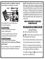
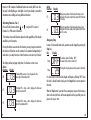
LIMITED ONE-YEAR WARRANTY
Atlas Model Railroad Company, Inc. warrants that this Commander will be free from
defects in material and workmanship for a period of one year from the date of purchase. If this Commander fails during the warranty period, carefully pack the item in
the original carton, together with the dated sales receipt, and return to: Atlas DCC
Warranty, 378 Florence Avenue, Hillside, NJ 07205. Defects due to misuse, improper maintenance and/or abuse are not covered by the warranty. Items that have been
disassembled by the modeler or anyone other than an authorized Atlas repair person
are not covered by the warranty. This warranty gives you specific legal rights and you
may also have other rights which vary from state to state.
INSTRUCTION MANUAL
The Atlas Master DCC Commander complies with Part 15 of FCC Rules. Operation is
subject to the following two conditions: (1) this device may not cause harmful interference, and (2) this device must accept any interference received, including interference that may cause undesired operation.
FOR TECHNICAL ASSISTANCE:
www.atlasrr.com
[email protected]
Atlas Model Railroad Co, Inc. • 378 Florence Ave. • Hillside • NJ • 07205
VERSION 3.2
ITEM #330
WELCOME TO THE ATLAS MASTER™ DCC SYSTEM!
TABLE OF CONTENTS
Getting Started...................................................................... 3
Decoder Preparation...3
Setting Up Your Layout To Run DCC...3
The Atlas Master DCC System and the related components have been designed to be
fun and easy to use so you can enjoy running your trains using the latest in digital
command control technology. Not only do you not have to be an electrical engineer,
but you will be running your trains in DCC mode in no time, if you follow the
Commander instructions contained in this manual.
Using the Atlas Master DCC Commander.................................. 6
Locomotive Addressing....7
Running Your Locomotive........................................................ 7
Controlling Speed...7
Changing Directions...7
Activating Functions...8
Emergency Stop...10
Recalling Locomotives (“stack” function)................................11
The Menu System..................................................................11
Accessing the Menu...12
Menu Selections...12
Controlling Turnouts...13
Setting Speed Steps...14
Decoder Programming...15
Consisting...20
System Settings...22
Expanding Your System.........................................................23
Adding More Throttles...23
Connecting Two Commanders...23
Characteristics of the Slave Commander...26
Adding More Power to Your Layout (Power Stations)...27
Warranty..................................................................Back Cover
1
ATLAS MASTER DCC SYSTEM COMPONENTS
The following is all you need to get started running your trains in
Digital Command Control:
1. Commander*: Controls your trains. Item #330
2. Generator : Provides power to the Commander. Item #335
3. Decoder*: Atlas offers an HO scale multi-function Dual-Mode
Decoder™ that, once installed, allows you to easily switch the operation of
your locomotive from analog to digital mode. This function enables you to
run your decoder-equipped engines on an analog layout without the typical
speed differential. N scale multi-function decoders are also available. Some
HO & N scale Atlas locomotives have decoders factory-installed, for your
convenience. See our web site for further details. www.atlasrr.com
* These Atlas Master DCC System components conform to the NMRA DCC
standards and are also compatible with items from other DCC
manufacturers.
If you would like to add walk-around capability to your layout, consider using
Atlas' HandCommand™ throttle (Item #331). Perfect for use with the Atlas
Master DCC system, the handheld unit comes complete with everything you
need to add walk-around capability (including a panel mount, coiled cord and
2
flat wire) and it supports XpressNet technology. Visit the DCC section of our
web site for more information at www.atlasrr.com
MISCELLANEOUS ITEMS YOU WILL ALSO NEED:
• Atlas Colored Layout Wire: (or any18-20 gauge stranded wire). Items
#315-#319
• Terminal Joiners: HO - Item #842; N scale - Item #2539
• Insulated Rail Joiners: HO - Item #55; N scale - Item #2538
• Mini flathead screwdriver
18VDC, 45va to 55va transformer in place of an Atlas Generator.
2. Connect the Commander to your track leads. Connect the wires from
your terminal joiners, or other track leads, to screw terminals J & K on the
Commander. Use 18-20 gauge stranded wire to extend your leads, if necessary. IF YOU NEED ADDITIONAL INFORMATION, PLEASE SEE www.atlasrr.com
(in DCC section).
*CAUTION: If you use
GETTING STARTED
Decoder Preparation
Before you can use your Commander, you must have a decoder installed in
any locomotive you wish to run in DCC mode. Please note that Atlas DualMode Decoders factory-installed in HO scale Atlas locomotives come set-up in
Analog mode. To switch from Analog to Digital mode, please refer to the
instructions that came with your locomotive.
Setting Up Your Layout to Run DCC
Any analog layout that is run using a standard DC power pack can be converted to run as a digital layout controlled by a DCC system. Here are the steps
to convert your layout to run DCC using the Atlas Commander:
(See Fig. 1 on page 4 for location of terminals on the Commander.)
1. Connect the Generator to the Commander. Connect terminals U & V
on the Commander to the output terminals of the Generator, using stranded
18-20 gauge wire. Please note that you may use any 14 to 16VAC, 14 to
3
FIGURE 1
an Atlas Selector and your
layout is using common
rail wiring, as in all Atlas
layout plans, P & J must
go to the common rail.
Terminal Q & K must go to
the A & B input of the
Selector. Otherwise an ER1
message will be displayed.
3. Create a Programming Track Section. The programming track section
allows you to program your decoder-equipped locomotive. First, you must isolate a section of track from your mainline (such as a siding), using plastic insulated rail joiners. Second, connect the non-insulated end of your programming
track section (using terminal joiners or other track leads) to screw terminals P
& Q on the Commander. If you prefer, you can use an Atlas Controller (Item
#220) to apply mainline track power or programming track power to the insulated track section.
4
4. Using an Atlas Controller to select Mainline or Program track.
Connect the Commander to an Atlas Controller as shown in Figure 2.
SIDING/
FIGURE 2
PROGRAMMING
TRACK
J
K
MAIN TRACK
CAB A
REVERSING
SWITCH
P
A
Q
B
PROGRAM
TRACK
C X Y
X-Y
CAB
SELECTOR
DIRECTION
SWITCH
CAB B
REVERSING
SWITCH
CONTROLLER
• Connect the Controllers X & Y screws to the siding or section of
track to be used for programming.
To Use Siding For Mainline:
• Set the A & B reversing switches in the center position.
• Set the A / B switch to the A position.
• Set the X/Y reversing switch so the train can enter the siding/
programming track without shutting down the Commander.
To Use Siding For Programming:
• Set the A / B switch to the B position for programming.
5. Plug the Power Cord of the Generator into a 120VAC power
outlet (US standard).
Please note that terminals C & D may be used to add additional Power
Stations. Please see page 27 for an explanation of Power Station usage.
XpressNET is a high-speed digital network based upon the industry standard
RS-485 protocol. The Atlas Commander uses XpressNET to communicate
between its high-speed components such as the HandCommand. XpressNET
communicates at 62.5 thousand bits per second (nearly 4 times faster than its
closest competitor). It is the highest performance network in widespread DCC
use and all its protocols are freely available to both the industry and the hobbyist. XpressNET is an industrial based technology, which can be setup in an
infinite number of possibilities, making it simple to setup and control any layout, large or small.
NOW YOU'RE READY TO RUN YOUR
TRAINS WITH DCC!
USING THE ATLAS MASTER DCC COMMANDER
Buttons And Their Function
Dial - Used to control the speed of the selected locomotive.
and - Used to select the direction of the selected locomotive. Press both
buttons simultaneously to access the Menu system.
Stop - Press this button to turn the track voltage on or off. Also press this button to turn the track voltage on after removing a short from the track.
F0, F1, F2* - Use to control locomotive and accessory decoder functions.
These buttons are also used for Menu operations. When in the menu, F0 functions as the Enter button and F2 functions as the Exit button.
Press and hold the Forward or Reverse button and press F1 to control
function 3 (F3) or F2 to control function 4 (F4).
5
6
* The number of accessible functions depends on the capabilities of the
decoder installed in your locomotive.
“+” and “-” - Used to select the address of the locomotive you wish to
control. When in the Menu use to select Menu options or to set parameters.
Understanding Locomotive Decoder Addressing
Each decoder-equipped locomotive has an address. The address is how the
Commander identifies which locomotive it is controlling at any given time.
Using the Commander you can easily control the speed, lights, and other functions (if available) of up to 99 engines!
To program a locomotive's address, go to page 15.
RUNNING YOUR LOCOMOTIVE
When you turn the Commander "on", the display will default to the Locomotive
display, Lxx (xx is a locomotive address). Select the locomotive you desire to
control using the “+” and “-” buttons. Once you've reached the desired
address, you may acquire the locomotive by adjusting the speed, changing the
direction of the locomotive, or activating a function.
Controlling the Speed of Your Locomotive
The speed of the selected locomotive is controlled with the dial. Turning the
dial clockwise increases speed, turning it counter clockwise decreases the
speed. In full counter clockwise (ccw) position the locomotive stops and the full
clockwise position sets maximum speed.
Changing Directions
The and buttons are used to control the direction of the selected locomotive:
Key
Display
.
L 03
L .03
Forward - A dot will appear to the
upper left of the centermost LED.
Reverse - A dot will appear to the
lower left of the centermost LED.
The direction of travel changes only after the key is released. The display will
show the selected direction.
If you change the direction while the locomotive is still moving (speed dial not
fully ccw), the locomotive will decrease speed (brake) with the preset deceleration setting until it comes to a full stop and then accelerate in the opposite
direction with the preset acceleration setting. For more information on acceleration and deceleration settings (and programming same), see page 16.
Activating Functions*
Buttons F0, F1 and F2 are used to control functions on the selected locomotive, and to control turnouts or other accessories via an accessory decoder. For
information on controlling your turnouts, please see page 13.
Function zero - F0 - controls the front and rear light headlight (these lights
are directional by default and may be configured for independent control).
The user may configure function 1 -F1, function 2 - F2, function 3 - F3, and
7
8
function 4 - F4. Examples of additional functions are sound, (bells, horn, whistle) and / or ditch lighting, or strobe lights. Consult your decoder's manual for
information on installing and using additional functions.
Activating Functions 3 & 4
Press and hold a direction button , or
Function 3, or F2 to control Function 4.
, and press F1 to control
*The number of accessible functions depends on the capabilities of the decoder
installed in your locomotive.
Pressing the button once activates the function, pressing it again de-activates
the function. All functions can be activated or de-activated independently of
each other so you may have two or three functions on at one time, if desired.
The displays below and upper right shows if a function is active or not:
Active
Function Display
F0
F1
F2
9
.
L. 03
.
L 0.3
.
L 03.
If function F0 is active, a dot is displayed to the
lower right of the leftmost LED.
If function F1 is active, a dot is displayed to the lower
right of the center LED.
If function F2 is active, a dot is displayed to the lower
right of the rightmost LED.
Active
Function
F3
F4
Display
.
L 0.3
.
L 03.
While pressing either of the direction buttons a dot is
displayed to the lower right of the center LED if function
F3 is active.
While pressing either of the direction buttons a dot is
displayed to the lower right of the rightmost LED if function F4 is active.
Emergency Stop
In case of a foreseeable train crash, operation can be stopped by pressing the
Stop key:
Key
Display
Stop
Stop
OFF
.
L. 29
The display shows a flashing "OFF".
The power to the track is turned off.
Pressing the Stop key again restores power to the track.
If a short occurs on the track the display will display a flashing "OFF". Once
the short is cleared from the track, press the Stop button to restore power to
the track.
When the Stop button is pressed after an emergency stop or after clearing a
short on the track, all trains will resume operation at the speed they were set
prior to the stop or short.
10
RECALLING LOCOMOTIVES
The Commander has a “stack” feature which remembers the last eight locomotives acquired. To recall a locomotive from the stack, press either the
Forward or Reverse button (depending on the direction the locomotive is traveling) and then the “+” or “-” button to scroll through the
stack until you reach the desired locomotive. Since the stack remembers the
last eight locomotives you have acquired; any locomotives acquired prior to
the last eight are not accessible via the stack. For example, if the stack contains locomotives 1,2,3,4,5,6,7,8, and you access another locomotive (ie.,
locomotive 9), the stack will forget locomotive 1 and remember locomotives
2,3,4,5,6,7,8,9. The locomotive which is dropped from the stack is the oldest
locomotive in the stack, not necessarily the lowest address.
Acquiring a locomotive that is currently running:
When selecting a locomotive from the stack, you may adjust the speed dial to
approximate the locomotive’s speed, prior to releasing the direction button.
When acquiring a locomotive directly, using the “+” or “-” buttons, select
the locomotive address on the display. Then press and hold the direction button which corresponds to the locomotives direction, and adjust the Speed dial
to approximate the speed of the locomotive, then release the direction button.
THE MENU
The Commander has a Menu System which is used for the following settings and functions:
11
• Controlling turnouts • Adjusting system settings • Setting speed steps
• Programming and reading decoder parameters • Consisting
Accessing the Menu
Press both Forward and Reverse buttons at the same time to access the
Menu system. The display changes and now shows the last used menu. You
may scroll through the menu choices using the “+” and “-” buttons.
When you reach the desired menu, press the Enter button to access the settings in that menu or press the Exit button to return to the locomotive display.
Menu Selections
This menu is used to control turnouts, or other accessories.
NOTE: You must have an accessory decoder attached to one or
more turnouts on your layout for this function. For more about
controlling turnouts, see next page.
SPE
This menu is used to select the speed steps of the selected
locomotive decoder.
This menu is used to display or program a decoder and its
parameters.
.
SY S
This menu is used to change the system settings.
This menu is used to setup or separate consists.
12
Controlling Turnouts or other Accessories
Speed Step Assignment
Accessory decoders, like your locomotives, require a unique address to allow
independent control. Most accessory decoders are programmed in groups of
four. I.E. (1,2,3,4), (5,6,7,8), (9,10,11,12), ... Accessory decoders must be
programmed like a locomotive decoder (consult the instructions included with
your accessory decoder for programming directions). After the required programming you can use the Function buttons on your Commander to control
the turnouts as described below and on the next page.
The speed range from a complete stop to maximum speed is divided in steps.
The larger the number of steps, the better the speed control resolution. I.E The
larger the number of speed steps the smoother the control of the locomotive.
The Atlas Commander supports 14,28, and 128 Speed Steps. Speed step settings are assigned for each locomotive, and each locomotive may be different.
Follow the steps below to view or change the speed steps for the locomotive
selected on the display.
1. Press both the Forward and Reverse buttons at the same time to
access the Menu system.
2. Press the “+” or “-” buttons to select the Turnout menu, Sch, then
follow the steps below:
Setting Speed Steps*
Display
What To Do
Press the Enter button to access the Turnout (switch) menu.
Use the “+” or “-” button to select the turnout (or Accessory
decoder) address you desire to control.
(Possible range is 1 through 99)
When you have reached the desired turnout address, Press
F0 or F1 to control the turnout.
The direction the turnout will throw will depend on how it is connected to the
Accessory Decoder. If the turnout direction is reversed, reverse the two control
wires connected to the Accessory Decoder.
13
1. Use the “+” or “-” button to select the address of the locomotive whose
speed steps you desire to view or change.
2. Press the Forward and Reverse buttons, at the same time to access
the menu system.
3. Press the “+” or “-” button to select the Speed Step menu, SPE, then
follow the steps below and on the next page:
*The locomotive must be on the main track and stopped (Speed dial fully
CCW) to change the speed steps.
Display
SPE
.
28
What To Do
Press Enter to access the Speed Step menu.
The display shows the current speed step setting for the
selected locomotive.
14
Display
.
28
.
4
What To Do
Press the “+” or “-” button to select the desired speed step
(14, 28 or 128)*.
Once the desired speed step appears, press Enter to accept the
change, or Exit to return to the Menu selection without
changing the speed steps.
*The selected locomotive must be stopped (Speed dial fully CCW) to change
the speed steps.
Note: If the headlights on your locomotive blink on and off as the speed is changed,
the Commander is set for 28 speed steps and the locomotive decoder is set for 14
speed steps. If the lights do not turn on at all, the locomotive is set for 28 speed steps,
and the Commander is set for 14 speed steps. The Commander defaults to 28 speed
steps. So if your locomotive returns to 14 speed steps after losing power, or being
removed from the track, the locomotive is configured for 14 speed steps. To correct
this, read the current value in Register 5. Add 2 to the current value and save the new
setting. The default configuration value for most decoders is 6. Consult you system
manual for programming procedures.
Programming Your Decoder
If you wish to operate two or more individual locomotives at a time, each locomotive decoder must have a unique address. Most decoders come set to the
default address of “03.” The address of a decoder is changed through programming. Remember that there are two kinds of decoders: those that are
installed into locomotives, and those that are "accessory" or “stationary” and
are used to control turnouts or other accessories on your layout. A decoder’s
parameters are stored as Configuration Variables (CV’s). The Commander uses
Registers which correspond to these CV’s to program a decoder’s parameters.
15
Below is a list of parameters, and their corresponding CV’s and Registers found
in most locomotive decoders.
PARAMETER
Address
Start up voltage
Start up delay (acceleration)
Brake delay (deceleration)
General settings
Version number of decoder
software*
Manufacturer ID*
REGISTER NUMBER CONFIGURATION VARIABLE
R1
R2
R3
R4
R5
1
2
3
4
29
R7
R8
7
8
We will discuss programming a decoder's address. Follow the same steps for
programming registers 2 through 5. See your decoder manual for the range
of data and default settings of each register. *Registers 7 & 8 are read only.
STEP-BY-STEP DECODER PROGRAMMING
Please Note: Operation of the layout is disabled during programming (track
power is turned off). Connected slaves receive a signal through the XpressNet
cable about the pending programming. For more information about slaves,
please see page 23.
You may use these instructions to program a decoder installed in a locomotive,
or an accessory decoder that will be used to control turnouts. In the example
below, we guide you through programming the address of a locomotive
decoder. You would follow the same steps to program registers 2 through 5,
or an accessory decoder.
16
Programming A Locomotive’s Decoder Address
1. Place the locomotive to be programmed on the program track. For
information on creating a programming track see page 5.
2. Press both the Forward and Reverse buttons at the same time to
access the Menu system.
3. Press the "+" or "-" button to select the program menu, PRO, then
follow the directions below and upper right:
Display
What To Do
Press Enter to access the Programming Menu.
When you enter the Programming Menu register 1, r 1, is displayed.
To program your locomotives address press Enter. To select a
different register use the “+” or “-” buttons.
To read the current value of the selected register, press Enter
(in this example, the current locomotive address). If the
register is read successfully, the locomotives address will be
displayed.
In this example the current address is 24. If there is a problem
reading the current value or setting a new value, an error will
be displayed (see page 26 for error definitions).
To change the current value (in this example the locomotive
address), use the “+” or “-” button to select the new address.
The range for locomotive addresses is 1 to 255. Please note the
Commander can not access addresses above 99. (Consult your
decoder manual for acceptable settings for other registers.)
17
Once you have selected the new value, Press Enter to set the
new value. If the new value is accepted, the new setting is
displayed. In the case of an error message, see page 26 for
definitions.
Press Exit to return to the Register selection menu. You may
then select another register using the “+” or “-” button, or
Press Exit to return to the System Menu.
Direct Mode Programing
When you enter the program menu on the Commander, the Commander
defaults to Register Mode for programming. If your decoder supports Direct
Mode programming the Commander will allow you to access any of the
Configuration Variables supported by your decoder.
To access Direct Mode you must first read any of the basic eight registers.
When you read any of the registers, the Commander performs a test to determine if your decoder supports Direct Mode. If your decoder supports Direct
Mode, you may access its CV's by following the steps below:
1. Place the locomotive on the program track.
2. Press both the Forward and Reverse buttons at the same time to
access the Menu system.
3. Press the “+” or “-” button to select the program menu, PRO, then
follow the directions on the next page:
18
Display
What To Do
Press Enter to access the Program Menu.
Use the “+” or “-” button to select a register, and press Enter.
Press the Enter button to read the current value.
15
Once the Commander reads the current value, press the Exit
button to return to the register selection menu.
Use the “+” button to select register 8.
CONSISTING
Consisting your Locomotives
1. Use the “+” or “-” buttons to select the address of the locomotive you
wish to add to a Consist.
2. Press the Forward or Reverse buttons to set the direction that
the locomotive will operate in the Consist.
3. Press the Forward
and Reverse buttons at the same time to access
the menu system.
4. Press the “+” or “-” buttons to select the consist menu, nu, then follow
the directions below:
Display
What To Do
Press Enter to access the Consist Menu.
8
Press the “+” button again.
Press the “+” or “-” button to select the address you wish to
use to control the Consist.
If the display changes to c09, you are now in Direct Mode.
If the display returns to r1, your decoder does not support
Direct Mode.
Once the Commander is in Direct Mode, you may access any of the CV's supported by your decoder (see Decoder manual for further information).
If your decoder does not support Direct Mode programming, you may use
another decoder to pass the Direct mode test, and then switch back to the
decoder you would like to program. While you may not be able to read the
CV's of your decoder, you may still be able to set a new value.
19
xx
Press the Enter button to add the selected locomotive to the
Consist, or press Exit to return to the locomotive display. (xx is
the Consist address)
Note: The Consist address can be the address of an actual locomotive or an
unused address.
Add additional locomotives to the consist by repeating steps 1 through 5.
If a locomotive is part of a Consist, the display will indicate this by replacing
the "L" with an "N", or "n". If the display shows "N", the locomotive address
20
is the Lead address. If the display shows "n" the address is part of a Consist,
but not the Lead address.
While a locomotive is part of a Consist, you may select the locomotive to
change any functions as desired. While making changes to a locomotive in a
Consist, any speed or direction changes will effect the entire consist.
Removing a Locomotive from a Consist
1. Use the “+” or “-” buttons to select the address of the locomotive you
wish to remove from the Consist.
2. Press both the Forward and Reverse buttons at the same time to
access the system menu.
3. Press the “+” or “-” buttons to select the Consist Separation Menu, NUthen follow the directions below:
Display
What To Do
Press Enter to access the Consist Separation Menu.
The display will flash, indicating that you are about to remove
the selected locomotive from a Consist.
L xx
Press Enter to remove the selected locomotive from the
Consist, and return to the locomotive control display, or press
Exit to return to the menu selection.
SYSTEM MENU
System Settings
The following system parameters can be edited or viewed:
• Version number of the Commander software (view only).
• Service number of the Commander. You will be asked to identify this
number if you call in for assistance with your Commander (view only).
• If your Commander is set to function as a master or as a slave (also called
an XpressNET unit).
1. Press both the Forward and Reverse buttons at the same time to
access the Menu system.
2. Press the “+” or “-” buttons to select the System menu, SYS, then
follow the directions below and on the next page:
Display
.
SY S
.
Y
Press Enter to access the System Menu, or press Exit to return
to the Locomotive display.
(Use the “+” or “-” buttons to select one of the following
System Settings:)
Displays the Commander software version number.
Press Enter to view the version number. This selection cannot
be changed. Press Exit to return to the System Menu.
.
21
What To Do
Y 2
Displays the Commander Version number.
22
Display
What To Do
02
.
Y90
Press Exit to return to the Menu Selection. Press Enter to view
the version number. This selection cannot be changed.
This menu allows the Commander to be set for either Master or
Slave mode. Press Enter to change the Commanders mode.
.
SY S
.
Y90
What To Do
Press Enter to access the System Menu.
Use the “+” or ”-” button to select Y90. Press Enter to access
the configuration menu.
Press “+” button to set the Commander to operate as a Master
Commander. Press Enter to accept the change.
Use the ”-” button to change the display to “con”.
Press the “-” button to set the Commander to operate as a
Slave Commander. Press Enter to accept the change.
Connect the XpressNET cable from the Master Commander to
the Commander. Press Enter.
EXPANDING YOUR SYSTEM
Adding Additional Throttles
If you would like to have more than one operator on your layout, you may
add up to five additional Commanders (as Slaves), HandCommands, or any
other XpressNET compatible device to your Master Commander. When adding
additional Commanders, they must be configured as a Slave Commander.
Follow the steps below to configure your Commander as a Slave:
1. Connect the Commander to be configured as a Slave to a Generator and
plug the Generator in.
2. Press both the Forward and Reverse buttons at the same time to
access the Menu system.
3. Press the “+” or “-” buttons until the System Menu, SYS, is displayed
and follow the directions above right:
23
Display
Your Commander is now configured as a Slave Commander. You may disconnect the Commander from the Generator, unless you intend to use the Slave
Commander for programming.
If you are adding more than one Slave Commander to you system you must
select a different XpressNET address for each Slave Commander. Follow the
steps below to select an now XpressNET address:
1. With the Slave Commander connected to either the XpressNET, or a
Generator, press both the Forward and Reverse buttons at the same
time to access the Menu system.
2. Press the "+" or "-" buttons to select the System Menu, SYS, and follow
the directions on the next page:
24
Display
.
SY S
.
Y1 0
.
01
31
What To Do
Press Enter to access the System Menu.
Use the “+” or “-” button to select the XpressNET address
menu.
Press Enter and the current XpressNET address is displayed.
Use the “+” or “-” button to select a different address. The
range is from 1 to 31. Each XpressNET device must have a
unique address.
Press Enter to accept the new value, and to return to the
locomotive display.
While a Slave Commander is connected to the XpressNET, you will see one
additional selection in the System Menu.
Display
.
Y 3
30
25
What To Do
Displays the version number of the Master Commander.
This is a read only selection.
CHARACTERISTICS OF THE SLAVE COMMANDER
• The Slave Commander cannot be used to power the track.
• The Slave Commander does not require a connection to a Generator to
operate. However if you do connect a Slave Commander to a Generator, it
may be used for programming. The advantage of using a Slave
Commander for programming is you can continue to operate your layout
while programming with the Slave Commander.
• Full selection of all locomotive and accessory addresses.
Error Messages:
• Er1 - A short circuit has been detected on the programming track. Check
the decoder installation, making sure the motor and all rail pickups are
insulated from each other.
• Er2 - No value was found during the readout of the selected register, or
no response was received from the decoder. However this does not mean
the decoder did not accept the new value. Try running the locomotive with
the new values before attempting to reprogram. Also, make sure the
locomotive is on the program track, and the program track is connected to
terminals P & Q on the Commander.
• Er3 - The speed of the locomotive you are adding to a Consist is not set to
0 (fully CCW). Press Exit to return to the locomotive display, set the speed
fully CCW, and then add the locomotive to the Consist.
• Er9 - The Commander is set in Slave Mode and is not connected to an
active XpressNET. See page 24 for instructions to set your Commander in
the proper mode.
26
ADDING MORE POWER TO YOUR LAYOUT
• Any trains (including lighted passenger cars) that you run on your layout
require power to operate. The more trains you run, the more power your layout will need. As your layout grows, you may need to add additional power to
meet you power needs.
• The Commander is capable of supplying 2.5 amps of power continuously,
and will shut down if the power exceeds 3.0 amps. You can, however, add up
to three additional power stations to you Commander to supply additional
power.
• To add additional power to you layout, you must first divide your layout
into separate electrical blocks called power districts. Each power station then
supplies power to one or two districts.
• All power stations are connected to the Commander via terminals C & D.
The Commander then sends a low power DCC signal to each of the power
stations, which amplifies that signal and applies it to each of their
power districts.
• For more information on this or any other Atlas Master DCC product, see
our web site www.atlasrr.com
• Note: The Atlas Generator is not a power station and should not be connected to terminals C & D. Doing so may damage the Commander and void your
warranty. (See back cover for warranty information)
27
NOTES
28