1
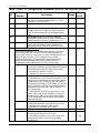
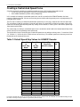
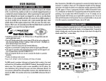
Locomotive decoder LE063XF
1
User Manual – Atlas/Lenz
LE063XF DCC Decoder for
Atlas N Scale Locomotives
The LE063XF DCC decoder is designed to fit a number of Atlas N scale locomotives, including the B23-7, B30-7,
B36-7, C628, C630, Dash 8-32BW, Dash 8-40B, Dash 8-40BW, GP-38, DCC-ready GP-40, GP-40-2, DCC-ready
SD-7, DCC-ready SD-9, SD-35, Train Master, and U25B locomotives. The characteristics of this decoder are:
•
•
•
•
•
•
•
•
•
•
Provides 0.5 amperes continuous motor current.
Provides two on/off function outputs that can be configured either for directional lighting or for full Rule 17
lighting.
Provides control of headlight dimming (by setting a CV).
Supports both short (2-digit) and long (4-digit) addressing
Supports advanced consist control (lashing up locomotives that have different DCC addresses)
Operates on conventional DC layouts; this feature may be disabled by setting a CV.
Provides full support for all forms of programming that are described in NMRA RP-9.2.3.
Supports both short form instructions and long form instructions in operations mode programming
(programming on the main line)
Can be set for operation with 14/27 speed-steps, 28/55 speed-steps, or 128 speed-steps with direct drive.
Has a rich set of properties, which can be set by the user to customize the decoder to a particular
locomotive.
Note: Since the LE063XF DCC decoder has been discontinued by Atlas and
is no longer available for purchase, this manual is for reference only.
Atlas Item # 518299, the AN12A0 Four-Function DCC Decoder for Atlas N
Scale Locomotives, is a suitable substitute for the discontinued LE063XF
DCC decoder. NCE Corporation manufactures the AN12A0 decoder for
Atlas Model Railroad Co., Inc.
Atlas Item #s 447199 & 447299
Manual Revised 06/25/2014
Atlas Model Railroad Co., Inc.
Locomotive decoder LE063XF
2
LE063XF Universal DCC Decoder
The LE063XF N-scale DCC decoder can be used with all popular NMRA-compliant DCC systems. This decoder
is in full conformance with all NMRA Standards and Recommended Practices and has been augmented to work
well with all major DCC systems on the market.
Although the LE063XF decoder has a low price, it is packed with all the features that you expect in a high-end
decoder:
•
Directional or independent lighting (both of which can be dimmed using DCC function keys),
•
Supports both short (2-digit) and long (4-digit) addressing,
•
Advanced consist control (operating and controlling several locomotives as if they were a single entity by
sending speed and direction commands to a common consist address that is stored in the decoder of every
locomotive in the consist),
•
Operations mode programming (programming on the main line),
•
Full support for all the various motor speed-step modes, including the 128 speed-step mode.
Many characteristics of the LE063XF decoder can be programmed to customize the decoder to its locomotive.
Please read The Configuration Variables and their Definitions section for details on the configuration variables
supported by the LE063XF. The LE063XF decoder supports all forms of programming described in NMRA
Recommended Practice 9.2.3, including the user friendly direct CV (Configuration Variable) programming mode
and operations mode programming. For example, you can operate the decoder with the factory-default speed
curve, or you may specify your own customized speed curve. You can also set which end of the locomotive is to
be the forward end. You can even decide whether or not you want to be able to operate the locomotive on
conventional DC layouts. If your DCC system supports operations mode programming, you can change the
values of all CVs (except for the locomotive’s 2- and 4-digit addresses in CV1, CV17, and CV18) while the
locomotive is on the main line.
Preparing to Install the LE063XF Decoder
Before installing the LE063XF decoder in your locomotive, it is necessary to test (and adjust, if necessary) the
locomotive for proper operation on conventional DC power. Replace any worn out parts, such as brushes. Also
clean any dirt or oxidation from the wheels and pickups to in order to insure that electrical contact is good. Now is
also a good time to lubricate your locomotive. A locomotive that runs well under conventional DC will also run
exceptionally well under DCC.
The LE063XF decoder is quite small and will fit into the B23-7, B30-7, B36-7, Dash 8-40B, GP-38, DCC-ready GP40, GP-40-2, DCC-ready SD-7, DCC-ready SD-9, SD-35, Train Master, and U25B locomotives.
Precautions to Take When Installing the Decoder:
Although the LE063XF decoder has many internal safeguards to prevent damage, you must not allow any metal
part of the locomotive to touch surface components of the decoder other than the pickup pads on the decoder that
connect to the wheel-sets, the headlights, and the motor. Any contact to other parts of the decoder can cause
a direct internal short circuit and destroy the DCC decoder.
The LE063XF decoder is not completely protected against static electricity and has sensitive electronic parts.
When installing this decoder in your N scale locomotive, it is recommended that you wear a grounded anti-static
wrist strap. Also be careful in handling the decoder, especially in the area around the top rear part of the decoder
(the area where the microprocessor is located).
The LE063XF comes with two LED headlights already installed. The light outputs of this decoder are
designed only to drive these LEDs. The Atlas warranty is void if these LEDs are removed from the
LE063XF circuit board.
Atlas Model Railroad Co., Inc.
Locomotive decoder LE063XF
3
Step by Step LE063XF Decoder Installation Procedure
In the following steps, please refer to the instructions provided with your Atlas locomotive.
1. Remove the locomotive's body shell and fuel tank. Use care so as not to damage any of the fragile parts.
2. Loosen the two screws that hold the frame together; these screws are located at the front and rear of the
frame.
3. Carefully remove the lighting control circuit board, which is located at the top of the frame.
4. Place the decoder between the two halves of the frame so that the two motor contact pads are at the
bottom of the decoder and will press firmly against the two copper contact strips from the motor when the
decoder installation has been completed. In the photograph of the bottom of the LE063XF decoder on the
first page, these motor contact pads are the two rectangles in the narrow center portion of the circuit
board.
5. Carefully press the two frame halves together, with the sides of the decoder inserted into the notches in
the two halves of the frame. Some pressure is needed to press the two frame halves together. This
pressure fit insures good electrical contact between the frame and the decoder.
6. Tighten the two screws that hold the locomotive frame together.
7. Carefully check to make sure that the motor contact strips are not touching either half of the frame. It is
necessary to look down from the top through the frame cutouts in order to check for such unwanted
shorts,
Note: There must be NO electrical contact between the motor contacts and any part of the frame!
8. Place the locomotive (without its body shell) on your DCC programming track and read back the
locomotive's address from the decoder. If the decoder is properly installed, you will be able to read back
the factory pre-set address 03. If your DCC system does not support reading decoder properties, observe
carefully the decoder's behavior while on the isolated programming track. Each time you try to program
the decoder you can see the acknowledgement that is sent by the decoder in the form of a brief and minor
jerk of the locomotive. A successful acknowledgement means that you have installed the decoder
correctly.
9. Remove the locomotive from the programming track and, if necessary, correct any installation errors.
10. Once you have successfully programmed the decoder, reinstall the body shell and retest the locomotive
on the programming track. If this test is successful, the locomotive is ready to use.
Programming the LE063XF Decoder
The LE063XF decoder supports all forms of both service mode (programming on an isolated programming track)
and operations mode programming (programming on the main line). Using any of these programming methods,
many features (such as the locomotive's address, acceleration, and configuration) can be customized to the
individual locomotive in which the decoder is installed. These customized properties will be saved in non-volatile
memory locations on the decoder so that they will retain their values even after power has been removed. All
parameter values are set electronically, which means that the locomotive does not need to be opened again after
the decoder has been installed in order to read or modify the values of these so-called Configuration Variables
(CVs). The LE063XF decoder has a total of 128 CVs. Not all of them are used at this time because many have
been reserved for future use.
Any NMRA-compliant DCC Command Station, such as the Atlas Master Commander, can be used to program the
LE063XF decoder. With several entry-level systems, only CV #1 (the locomotive address) can be set unless you
use a separate DCC programmer. More advanced DCC systems, including the Atlas Commander, support the
ability to set many more CVs. The LE063XF decoder supports all programming modes and can be programmed
by all NMRA-compliant DCC systems. The locomotive’s 2- and 4-digit addresses in CV1, CV17, and CV18
connot be programmed in operations mode. Instructions for reading and writing CVs are given in the user
manual of your DCC system.
Note: In order for newly programmed CV values INCLUDING A RESET (SETTING CV8 = 33) to take effect
after service mode programming, the decoder must go through a power reset. If your DCC command
station does not support automatic power reset, simply rock the locomotive off the track after
programming.
Atlas Model Railroad Co., Inc.
Locomotive decoder LE063XF
4
Configuration Variables and their Definitions
The LE063XF decoder supports a full range of features, which are activated by setting Configuration Variables.
All CVs are numbered. These numbers are used during programming and are identical for all decoders that
conform to NMRA standards, regardless of the decoder manufacturer. The following table lists the CVs supported
in the LE063XF decoder. Both CV numbers and Register numbers are provided for cross-reference.
Some CVs (such as CV29) have specific meanings for each bit. In order to conform to the NMRA convention for
bit numbering, the CV bit assignments shown in this table use the bit-numbering scheme of 0 to 7.
Table 1: Configuration Variables (CVs) for the LE063XF Decoder
CV
Register
Number
1
1
2
2
3
3
4
4
-
5
6
7
7
8
8
Description
Range
Default
**
Value
Short address:
This is the number that you enter into your DCC
system to tell it the locomotive you wish to run with a
short (2-digit) address.
Start voltage:
This is the voltage applied to the motor in speed step
1. Set this value so that the locomotive just starts
moving in speed step 1.
Acceleration Momentum:
Determines the rate of change of speed upon
acceleration. A higher value leads to a slower
acceleration.
Brake Momentum:
Determines the rate of change of speed upon braking.
A higher value leads to longer braking distances.
Contains CV29 (see definition of CV29 below)
Page Register:
Normally this Register is not modified directly by a
user. For correct operation, R6 should be set to have
the value “1” after any use.
Version Number:
This location stores the version number of the
decoder. This CV is read-only.
Manufacturers Identification:
This value is the manufacturer ID of the decoder,
(Atlas=127). Writing the decimal number “33” to
this Register will reset all CVs in the decoder to
their factory-default values EXCEPT FOR the
speed step settings in CV67 to CV94. However, in
order for this reset to take effect, after writing to
CV8 on the program track, you MUST cycle power
to the decoder (first off and then on again). One
simple way to do this power cycling is to tip the
locomotive to one side so that all the wheels on
the other side are off the rails, hold the locomotive
in this tipped position for 5 to 10 seconds, and
then slowly lower the locomotive back down so
that all wheels are again on the program track
rails.
1-127
3
1-15
8
1-31
1
1-31
1
0-55
0-127
6
1
-
45
-
127
Atlas Model Railroad Co., Inc.
Locomotive decoder LE063XF
5
Table 1 (cont. 1): Configuration Variables (CVs) for the LE063XF Decoder
CV
Bit
Number
17
-
18
-
19
-
23
24
29
Description
Long Address, High Byte
The long (also called extended) address, if used, is
contained in CV17 and CV18.
Long Address, Low Byte
Advanced Consist Address
The Advanced Consist address, if used, is stored in
CV19. (In Atlas Commanders the allowable range is
1-99.)
Acceleration Trim This CV contains additional
acceleration rate information that will be added to (or
subtracted from) the base value contained in CV3.
Deceleration Trim This CV contains additional
braking rate information that will be added to (or
subtracted from) the base value contained in CV4.
Decoder Configuration, Byte 1:
Several decoder properties are set with CV29. Changes are easiest if
done in binary mode, but can also be done by adding together the
decimal values (shown in parenthesis) for all the desired features and
writing the total into CV29. (For an example, see the section
Converting Binary Values of Individual Bits within a Configuration
Variable into the Equivalent Decimal Value of the Entire CV.)
The definitions for the individual bits of CV29 are given below.
Bit 0
Locomotive direction:
This bit sets the direction that the locomotive will move
when told to move forward in digital (DCC) mode.
0 = locomotive’s direction is normal
1 = locomotive’s direction is reversed
Bit 1
Headlight mode:
0 = Operation with 14 or 27 speed-step systems. This
setting must be selected when the locomotive decoder
is used with any DCC system that does not support
the 28 speed-step mode. If the headlights turn on and
off as the speed is increased, the command station is
configured for 28 speed-steps, and the decoder is set
for 14 speed-steps.
1 = Operation with 28, 55 or 128 speed steps. If you
use this setting, the Command Station must also be
configured to use either the 28 speed-step mode or
the 128 speed-step mode; otherwise, the headlights
cannot be controlled.
Bit 2
Usage on conventional DC layouts:
0 = locomotive operates only in digital (DCC) mode
1 = locomotive can operate in either analog
(conventional DC) or digital (DCC) mode
Bit 3
Always 0
Bit 4
Speed curve:
0 = Factory-default speed curve is used
1 = User-defined speed curve is used. Please enter
the appropriate values into CVs 67 to 94 before
setting this bit.
Range
Default
**
Value
192-231
0
0-255
0
0-255
0
0-255
255
0-255
255
0-55
6
0,1
0
(1)
0,1
1
(2)
0,1
1
(4)
0
0,1
0
0
(16)
Atlas Model Railroad Co., Inc.
Locomotive decoder LE063XF
6
Table 1 (cont. 2): Configuration Variables (CVs) for the LE063XF Decoder
CV
29
50
Bit
Number
Description
Decoder Configuration, Byte 1 (cont.):
Several decoder properties are set with CV29. Changes are easiest if
done in binary mode, but can also be done by adding together the
decimal values (shown in parenthesis) for all the desired features and
writing the total into CV29. (For an example, see the section
Converting Binary Values of Individual Bits within a Configuration
Variable into the Equivalent Decimal Value of the Entire CV.)
The definitions for the individual bits of CV29 are given below.
Bit 5
2-digit or 4-digit Addressing:
0= Short (2-digit) address used
1= Long (4-digit) address used
Bit 6
Always 0
Bit 7
Always 0
Decoder Configuration, Byte 2:
CV50 is similar to CV29, but CV50 is used to set other properties. The
definitions for the individual bits of CV50 are given below.
Bit 0
Not used
Bit 1
0 = CV23 and CV24 are not active
1 = CV23 & CV24 are active and contain acceleration
and deceleration trim values that are added to (or
subtracted from) CV3 and CV4, respectively.
Bit 2
Brake momentum on DC operation.
Used to achieve prototypical braking at red signal
indications if conventional DC control is disabled.
(CV29.2 = 0*)
0 = locomotive proceeds with track-voltage-dependent
speed inside the conventional. DC section.
1 = locomotive brakes in the conventional DC section
with preset brake momentum.
Bits 3-7
Not used
Range
Default
**
Value
-
-
0,1
0
0
0
0-6
(32)
0
0
0
0,1
0
(2)
0,1
0
(4)
Atlas Model Railroad Co., Inc.
Locomotive decoder LE063XF
7
Table 1 (cont. 3): Configuration Variables (CVs) for the LE063XF Decoder
CV
51
Bit
Number
67
to
94
105
106
Range
Directional or Independent Headlights:
CV51.0=0: Headlights are directional.
CV51.0=1: Headlights are independent per Rule 17,
with F0 controlling front headlight and F1
controlling rear headlight.
Bit 1
Dimming of Headlights:
CV51.1=0: Headlights cannot be dimmed.
CV51.1=1: Headlight can be dimmed, but.
- If CV51.0 = 0, dimming not supported
for directional headlights
- If CV51.0 = 1, dimming supported but
see explanations given below for Bits 2 and 3.
Bit 2
Front Headlight Dimming Control:
If CV51.1=1, the value in CV52 is used for front
headlight dimming with dimming controlled as follows:
- CV51.2=0: If CV51.0=0 (Dimming &
directional headlights both active), function F1
dims front headlight.
- CV51.2=1: If CV51.0=1 (Dimming & Rule 17
both active), function F4 dims front headlight.
Bit 3
Rear Headlight Dimming Control:
If CV51.1=1, the value in CV52 is used for rear
headlight dimming with dimming controlled as follows:
- CV51.3=0: If CV51.0=0 (Dimming &
directional headlights both active), function F1
dims rear headlight.
- CV51.3=1: If CV51.0=1 (Dimming & Rule 17
both active), function F4 dims rear headlight.
Bits 4-7
Not used
The value of CV52 is used for headlight dimming.
Using the value 0 for this CV results in a completely dark headlight,
when dimmed.
Using the value 255 for this CV keeps the headlight at its maximum
possible brightness, when dimmed.
Speed Step Values for Customized Speed Curve
These CVs are used to specify the speed step values for a customized
speed curve. The factory-default values for these CVs are specified in
Table 2 in the section Creating a Customized Speed Curve.
User Identification #1
User Identification #1
Default
**
Value
0
Lighting Special Effects:
Bit 0
52
Description
0,1
0
(1)
0,1
0
(2)
0,1
0
(4)
0,1
0
(8)
0-255
64
0-255
Factory-Default
Speed-Step
Values
0-255
0-255
255
255
* The notation CVx.y = z means that bit y of CVx has the value ”z”. For example, CV29.2 = 0 means that bit 2 of CV29 has the
value ”0.”
** In the Default Value field, the numbers shown in parenthesis () are the decimal values that must be written into a CV for the
specified bit of that CV to have the binary value “1”.
Atlas Model Railroad Co., Inc.
Locomotive decoder LE063XF
8
Converting Binary Values of Individual Bits within a Configuration Variable
into the Equivalent Decimal Value of the Entire CV
Reasons for Setting and Clearing the Individual Bits of a Configuration Variable
In order to make a DCC decoder perform in the manner that you wish it to perform, one must sometimes set or
clear individual bits of a CV. To program a DCC decoder using a DCC system that allows only the writing of
decimal values into CVs (such as the Atlas Master Commander), it is first necessary to convert the values of all
the individual bits of that CV that are to be set to the binary value 1 into their equivalent decimal values. It is then
necessary to add together all of these equivalent decimal values.
Procedure for Converting Individual CV Bit Values into a Decimal
Equivalent Value for the CV
The following table illustrates how to calculate the decimal value that must be written into a CV in order to set
and/or clear a specified set of individual bits within that CV
Each bit of a CV that is to be set to the binary
value “1” can be represented by the equivalent
decimal number shown in the second column
of this table. To determine the equivalent
decimal value to be written into the CV, first
write in column 3 of this table the decimal
equivalent values of all the bits of the CV that
are to be set to a binary 1. Write nothing in
column 3 for each bit of the CV that is to be
cleared, i.e., set to a binary 0. Then add up all
the numbers that you have written in column 3.
The sum that you get is the equivalent decimal
value you need to write into the CV.
Bit Number
0
1
2
3
4
5
6
7
Decimal
Equivalent
Decimal
Values for
CV
Calculation
1
2
4
8
16
32
64
128
SUM:
Example: Calculating the Default Value for CV29
From the definition of CV29 given in Table 1,
we see that the default values of bits 1 and 2
are binary 1s; whereas, all other bits in CV29
have a default value of binary 0.
In order to compute the decimal equivalent
default value of CV29, simply write in the
rightmost column of this table the number "2"
for bit 1 and the number "4" for bit 2. Then
add up all the non-zero numbers that you have
entered into this rightmost column. Since the
sum of these numbers is 6, the decimal
number to be programmed into CV29 is 6.
Bit Number
0
1
2
3
4
5
6
7
Decimal
Equivalent
1
2
4
8
16
32
64
128
SUM:
Decimal
Values for
CV
Calculation
2
4
6
Atlas Model Railroad Co., Inc.
Locomotive decoder LE063XF
9
Creating a Customized Speed Curve
Common reasons for specifying a customized speed curve for a DCC-equipped locomotive are to:
• Insure that dissimilar locomotives have the same performance characteristics
• Have model locomotives perform more prototypically.
In this example of creating a customized speed curve, we will assume that the LE063XF decoder has been
properly installed and tested. We also assume that you are familiar with the general process of programming CVs
using your DCC system.
The first step in creating a customized (non-default) speed curve is to assign a value to each internal speed step.
This assignment is done by specifying a value for each of the CVs from CV67 to CV94 using a table such as that
below, but substituting your desired speed step settings for the default CV values given in the Internal Speed Step
Value column of this table.
The second step in creating a customized speed curve is to write the value listed in the Internal Speed Step Value
column into the CV corresponding to that speed step.
The third and final step is to activate your customized speed curve by writing the binary value “1” into bit 4 of CV29
(i.e., CV29.4 =1). Unless this bit in CV29 has been set to a binary 1, the default speed curve that was preset into
the decoder at the factory will be used.
Table 2: Default Speed Step Values for LE063XF Decoder
Speed Step
in
14/27 Step
Mode
Speed Step
in
28 Step
Mode
Internal Speed
Step Value
(defaults shown)
CV
1
1
2
3
4
5
6
7
8
9
10
11
12
13
14
15
16
17
18
19
20
21
22
23
24
25
26
27
28
4
8
12
16
20
24
28
33
38
43
48
53
60
67
74
82
90
98
106
115
125
137
152
178
194
212
232
255
67
68
69
70
71
72
73
74
75
76
77
78
79
80
81
82
83
84
85
86
87
88
89
90
91
92
93
94
2
3
4
5
6
7
8
9
10
11
12
13
14
-
In order to calculate the correct speed-step value for the 128 speed-step mode, the LE063XF decoder will internally average
the values for 28 speed steps that were specified in (CVs 67 to 94).
Atlas Model Railroad Co., Inc.
Locomotive decoder LE063XF
10
Troubleshooting Decoder Programming Problems
Fault
Cause and Solution
Locomotive does not
move when you
address it on DCC
system.
Locomotive does not
move when DCC
system is set to the
address in CV1, even
though this address
can be read from CV1.
Locomotive does not
move when DCC
system is set to the
short address in CV1.
The short address can
be read from CV1, and
DCC functions can be
activated when the
DCC system is set to
the address in CV1.
Check to see if you have selected the correct address for that
locomotive.
DCC functions can be
activated when DCC
system is set to the
locomotive address, but
the locomotive does not
move.
The locomotive does
not appear to be using
the customized speed
curve values that you
have entered into CVs
67 to 94.
Function 0 (lighting)
cannot be switched on
and off.
Decoder is set to use a customized speed curve (CV29.4 = 1), but
you entered zero values into CVs 67 to 94. Either clear bit 4 of
CV29 or else enter suitable non-zero speed step values into CVs
67 to 94.
Locomotive headlights
are only illuminated
when the locomotive
speed is increased or
decreased; the
locomotive headlights
go on and off as the
locomotive speed
changes.
You have entered the short address (CV1), but the decoder is set
to use the long address, i.e., bit 5 of CV29 has been set.
Use the long address or else clear bit 5 of CV 29.
Check whether to see if an advanced consist address has been
programmed into CV19, i.e., check to see whether or not CV19 has
a value greater than 0. If CV19 has a non-zero value, you must
either use this advanced consist address to operate the locomotive
or else program the value 0 into CV19.
Bit 4 is not set to “1” in CV29.
Matching of speed steps is incorrect: The decoder has been set to
28/128 speed steps, but the DCC system has been set to 14/27
speed steps.
Either set the DCC system to 28/128 speed steps or change the
decoder speed step setting to 14/27 speed steps. (CV29.1 = 0).
Matching of speed steps is incorrect: The decoder has been set to
14/27 speed steps, but the DCC system has been set to 28/128
speed steps. Either set the DCC system to 14/27 speed steps or
change the decoder speed step setting to 28/128 speed steps.
(CV29.1 = 1).
For Technical Assistance
www.atlasrr.com
[email protected]
Please save this manual for future reference.
Lenz GmbH formerly manufactured the LE063XF decoder for Atlas Model Railroad Co., Inc.
© 20014 Atlas Model Railroad Co, Inc; All Rights Reserved.
Atlas Model Railroad Co., Inc.