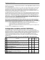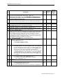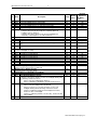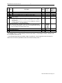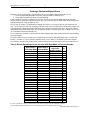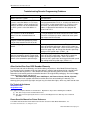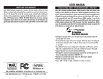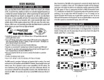
1
HO Dual-Mode™ 4-Function Decoder
1
USER MANUAL FOR ATLAS HO DUAL-MODE
4-FUNCTION DCC DECODER (ITEM #342)
By Dual Mode™, we mean that the Atlas’ #342 HO 4-function decoder has a jumper plug that allows the
modeler to select between DC-only operation or DCC and DC operation. With the plug in the DC-only
position, a decoder equipped locomotive runs on a standard DC powered (analog) layout with no speed
differential when compared to a similar non-decoder-equipped locomotive.
The #342 HO Dual-Mode™ 4-function decoder can be used with all popular NMRA-compliant DCC
systems. This decoder is in full conformance with all NMRA Standards and Recommended Practices and
has been augmented to work well with all major DCC systems on the market.
It can be installed in most Atlas HO scale engines with a motor-mounted lighting board produced since
1985 except for the S-series Alco switchers and the AEM-7/ALP-44 locomotives and may also be
installed in a number of locomotives from other manufacturers. Please note that this decoder does NOT
fit into Atlas HO Silver Series locomotives. Atlas Silver Series locomotives are the DCC-ready
counterparts of DCC-and-sound-equipped Gold Series locomotives. The reason why it does not fit is that
the #342 decoder is too long to fit into the opening in an Atlas HO Silver Series chassis.
Although the #342 decoder has been discontinued and is no longer available from Atlas, this document is
being re-issued to provide modelers who have older Atlas HO Master Series HO locomotives equipped
with 342 decoders with an up to date user manual.
As substitutes for the no longer available #342, Atlas recommends either the NCE DA-SR or the TCS
A4X. Both of these decoders are drop-in replacements for the #342 decoder, and both the DA-SR
decoder and the A4X decoders have many more features than the #342 decoder had.
Item #342 (DISCONTINUED)
Manual Revised 05/19/2015
___________________________________________________________________________________
Atlas Model Railroad Company, Inc.
HO Dual-Mode™ 4-Function Decoder
2
The Atlas 4-function decoder has most of the features that you would expect from a modern high-end
DCC decoder:
• Dual Mode (DC-only or DCC-and-DC) Operation
• Two on/off DCC unction outputs with a current rating of 100 mA each that can be configured for
directional or independent (Rule 17) lighting. This lighting is dimmable with DCC function keys.
Moreover, each output may optionally be configured as a Gyro light, Mars light, single pulse
Strobe light, or double-pulse Strobe light.
•
Two additional function outputs that may be configured for independent operation or as Ditch Lights
with an adjustable blink rate. These outputs may be controlled via DCC functions 1 through 8.
• Supports both short (2-digit) and long (4-digit) addressing.
• Advanced consist control (operating and controlling several locomotives as if they were a single
entity by sending speed and direction commands to a common consist address that is stored in
the decoder of every locomotive in the consist (i.e., Advanced Consisting).
• Support for all forms of programming described in NMRA RP 9.2.3, including Operations Mode
programming (programming on the main line).
• Full support for all the various motor speed-step modes, including the 128 speed-step mode.
• Choice of Silent Drive or Precision Glide motor control.
• Operation on conventional DC layouts while the decoder is in DCC Mode may be disabled.
• Decoder provides 1A continuous motor current.
• Size: 2.88" L x 0.68 W" x 0.26" H (40.5mm L x 17mm W x 3.3mm H).
ANALOG/DCC JUMPER PLUG
The position of the jumper plug determines the mode of the decoder. (See the figure on page 4.) To
operate the decoder the Analog (DC only) mode, move the jumper plug to the four holes closest to the
end of the decoder marked “Rear” in the figure on page 4. Conversely, to operate the decoder in Digital
Mode (either DCC or DC), move the jumper plug to the four holes in the PC board that are closest to the
center of the locomotive, as also shown in the figure on page 4. Make certain that the 8-pin plug is firmly
inserted into all four holes in the locomotive PC board.
Preparing to Install the Dual-Mode 4-Function Decoder
Before installing the #342 decoder in your locomotive, it is necessary to test (and adjust, if necessary) the
locomotive for proper operation on conventional DC power. Replace any worn-out parts, such as
brushes. Also clean any dirt or oxidation from the wheels and pickups to in order to insure that electrical
contact is good. Now is also a good time to lubricate your locomotive. A locomotive that runs well under
conventional DC will also run exceptionally well under DCC.
Precautions to Take When Installing the Decoder
Decoder Output Current Draw
An internal rectifier supplies the current for all the decoder outputs and has a maximum current rating of
1.2 amps (motor plus function outputs). Moreover, each individual function output is limited to a maximum
of 100 ma. Although summing up the individual current limits leads to a number larger than 1.2 amps, the
sum of all currents to the motor and the four function outputs cannot exceed this limit of1.2 amps.
Example:
The motor may require as much as 1.0 Amp, continuously. Hence, the current draw of all function
outputs combined must not exceed 0.2 A. For example, if a directional front headlight on Function A
requires 50 mA, then the load on Functions B, C and D must not exceed 150 ma.
Function Output Voltage
The voltage at the four function outputs is about two volts less than the DCC track voltage or about 12 to
13 volts with a nominal 14.5 volts on the track. The light bulbs or LEDs that are factory-installed in Atlas
locomotives already take this voltage into account. However, any time you connect an after-market LED
Atlas Model Railroad Company, Inc.
HO Dual-Mode™ 4-Function Decoder
3
to one of these function outputs, you must make sure there is a 1000 ohm resistor in series with one lead
of this LED.
IMPORTANT WARNINGS! Although the #342 decoder has many internal safeguards to prevent damage,
please follow these guidelines:
1. DO NOT allow any metal part of the locomotive to touch any metallic part on the #342
decoder PC board. This action could cause a direct internal short circuit, and the decoder will be
destroyed.
2. DO NOT WRAP the decoder with electrical tape or shrink-wrap! Doing so will impede air
circulation and degrade the performance of the decoder. Instead, put Kapton tape (preferably) or
electrical tape over any part of the locomotive frame or body that might touch metal parts on the
decoder. This method of insulation will prevent short circuits without 'suffocating' the decoder.
3. After removing all connections from the original light board, there must be no electrical
connection between the motor and the rail pickups.
4. If you need to extend any wires leads, use 26 gauge stranded insulated wire; Solder the splice;
and insulate all soldered connections with very thin heat-shrink tubing.
5. Solder using a low (20 to 25 watts max) wattage or temperature controlled soldering iron with a
very fine tip, any wires you need to connect to the four function FC and function FD soldering tabs
on the 4-function decoder
Step by Step Installation
The #342 4-function DCC decoder is designed to be installed in locomotives that have a motor-mounted
light board (except for Atlas Silver Series locomotives). It may also be installed in locomotives without a
motor-mounted light board by connecting 26 gauge or finer wire leads to the decoder terminals using the
supplied wire retainers.
The following steps are for installation in Atlas decoder-ready HO locomotives (except for Atlas Silver
Series locomotives). The steps for installation into other manufacturer’s locomotives may vary.
1. Remove the shell from your locomotive. (Refer to the locomotive manufacturer’s instructions.)
2. Remove the weights to allow access to the wire retainers. (See your locomotive parts diagram for
location of weights.)
3. NOTE THE POSITION OF THE RED & BLACK MOTOR WIRE LEADS (left vs. right). You will
need to connect these wires to the decoder in the same positions as they were connected to the
light board.
4. Remove the 10 wire retainers from the terminals on the light board. Then remove the wires from
the light board.
5. Remove the light board by pushing one of the black motor mount extensions toward the center of
the light board, and lift the light board off the motor mount. Remove the light board from the other
motor mount.
6. Locate the front of the Dual Mode Decoder and position the decoder over the locomotive. Place
one of the holes in the DMD over one motor mount and pull towards the other motor mount.
Then lower the 4-function decoder in place.
7. Insert the two wires from the front and from the rear headlights through the holes in the center
pair of terminals on the front and rear ends of the decoder. If the lights are LEDs, refer to the
diagram on page 4 for the proper polarity. (Reversed polarity causes no harm, but the LED will
not light.) Install wire retainers over each terminal to hold the associated wire in place.
8. Connect the four wires from the trucks to the four terminals on the four corners of the decoder
and install wire retainers over each terminal.
9. Connect the motor wires to the terminals on the side of the decoder in the same positions as they
were on the light board, and install wire retainers over each terminal.
10. NOTE: The wire retainers should be installed with the notched side up.
Atlas Model Railroad Company, Inc.
HO Dual-Mode™ 4-Function Decoder
4
11. Place the locomotive (without its body shell) on your DCC programming track, and read back the
locomotive's address from the decoder. (Refer to your DCC system’s instructions.) If the
decoder is properly installed, you will be able to read back the factory pre-set address “3." If
your DCC system does not support reading decoder properties, observe carefully the decoder's
behavior while the locomotive is on an isolated programming track. Each time you try to program
the decoder, you should see the acknowledgement that is sent by the decoder in the form of a
brief and minor jerk of the locomotive. A successful acknowledgement means that you have
installed the decoder correctly. If the decoder is installed correctly, you may program the
address and other parameters as desired.
12. If the decoder has been installed incorrectly, you will receive an error code. Remove the
locomotive from the programming track, and correct any installation errors.
13. Once you have successfully programmed the decoder, reinstall the weights and the body shell.
Then test the locomotive on the mainline. Be sure to test all functions. If this test is successful,
the locomotive is ready to use.
Top View of Atlas #342 4-Function Decoder Showing Locations of the Function Outputs
Programming the Dual-Mode 4-Function Decoder
Many characteristics of the #342 dual-mode 4-function decoder can be programmed to customize the
decoder to its locomotive. Please read The Configuration Variables and their Definitions section for
details on the configuration variables supported by the 4-function DMD. The 4-function #342 decoder
supports all forms of programming described in NMRA Recommended Practice 9.2.3, including both the
user-friendly Direct Mode on the program track and Operations Mode on the main line. For example, you
can operate the decoder with the factory-default speed curve, or you may specify your own customized
speed curve. You can also set which end of the locomotive is to be the forward end. You can also
decide whether or not you want to be able to operate the locomotive on conventional DC layouts. If your
DCC system supports Operations Mode programming, you can change the values of all CVs while the
Atlas Model Railroad Company, Inc.
HO Dual-Mode™ 4-Function Decoder
5
locomotive is on the main line except for the locomotive’s 2- and 4-digit addresses which are stored
in CV1, CV17, and CV18.
The customized properties you set with CVs are saved in non-volatile memory locations on the decoder
so that they will retain their values even after power has been removed. All parameter values are set
electronically, which means that the locomotive does not need to be disassembled again after the
decoder has been installed in order to read or modify the values of these Configuration Variables (CVs).
The #342 dual-mode 4-function decoder has a total of 128 CVs.
Any NMRA-compliant DCC Command Station can be used to program the #3422 dual-mode 4-function
decoder. With several entry-level DCC systems, only CV #1 (the 2-digit locomotive address) can be set
unless you use a separate DCC programmer. More advanced DCC systems support the ability to set
many more CVs. The #342 decoder supports all programming modes and can be programmed by all
NMRA-compliant DCC systems. Remember that the locomotive’s 2- and 4-digit addresses stored in
CV1, CV17, and CV18 cannot be programmed in Operations Mode. Instructions for reading and
writing CVs are given in the user manual of your DCC system.
Note: In order for newly programmed CV values to take effect after service mode programming
(programming on the program track) the decoder must go through a power reset. If your DCC
command station does not support automatic power reset, simply rock one side of the locomotive
off the track after completing your programming. One easy way to do a power reset is:
• Tip the locomotive to one side so that all the wheels on the opposite side are off the rail,
• Hold the locomotive in this tipped position for 5 to 10 seconds,
• Slowly lower the locomotive back down until all wheels are once again on the program track
rails.
This power cycling is extremely important; do not omit it.
Configuration Variables and their Definitions
The #342 dual-mode 4-function decoder supports many features, which are activated by setting
Configuration Variables. All CVs are numbered. These numbers are used during programming and are
identical for all decoders that conform to NMRA standards, regardless of the decoder manufacturer. The
following table lists the CVs supported in the #342 dual-mode 4-function decoder. Some CVs (such as
CV29) have specific meanings for each bit. In order to conform to the NMRA convention for bit
numbering, the CV bit assignments shown in this table use the North American bit-numbering
scheme of 0 to 7.
.
Table 1: Configuration Variables (CVs) for the #342 Dual-Mode 4-Function Decoder
CV
Description
Range
Default
Value**
1
Short address:
This is the number that you enter into your DCC system to tell it the locomotive
you wish to run with a short (2-digit) address.
Start voltage:
This is the voltage applied to the motor in speed step 1. Set this value so that
the locomotive just starts moving in speed step 1.
Acceleration Momentum:
Determines the rate of change of speed upon acceleration. A higher value leads
to a slower acceleration
Deceleration (Brake) Momentum:
Determines the rate of change of speed upon braking. A higher value leads to
longer braking distances
Contains CV29 (see definition of CV29 below)
Page Register:
Normally this Register is not modified directly by a user. For correct operation,
CV6 should be set to have the value “1” after any use.
Version Number:
This location stores the version number of the decoder. This CV is read-only.
1-127
3
1-15
8
1-31
1
1-31
1
0-55
0-127
6
1
-
46
2
3
4
-
7
Decimal
Equivalent
Of Binary
“1s”
Atlas Model Railroad Company, Inc.
HO Dual-Mode™ 4-Function Decoder
CV
8
17
18
19
23
24
29
29
Description
Manufacturer’s Identification:
This value is the manufacturer ID of the decoder. (Atlas=127).
Writing the decimal number “33” to CV8 AND DOING A POWER RESET will
reset all CVs in the decoder to their factory-default values EXCEPT FOR the
speed step settings in CV67 to CV94.
Long Address, High Byte
The long (also called extended) address, if used, is contained in CV17 and CV18.
Bit
1
29
Bit
2
29
Bit
3
Bit
4
Headlight mode:
0 = Operation with 14 or 27 speed-step DCC systems. This setting must
be selected when the locomotive decoder is used with any DCC system
that does not support the 28 speed-step mode. If the headlights turn on
and off as the speed is increased, the DCC command station is
configured for 28 speed-steps, and the decoder is set for 14 speed-steps.
1 = Operation with 28, 55 or 128 speed steps. If you use this setting, the
Command Station must also be configured to use either the 28 speedstep mode or the 128 speed-step mode; otherwise, the headlights cannot
be controlled.
Usage on conventional DC layouts:
0 = locomotive operates only in digital (DCC) mode
1 = locomotive can operate in either analog (conventional
DC) or digital (DCC) mode
Always 0
Speed curve:
0 = Factory-default speed curve is used
1 = User-defined speed curve is used.
Please enter the appropriate values into CVs 67 to 94 before setting this bit.
Range
Default
Value**
-
127
192
231
Long Address, Low Byte
Advanced Consist Address
The Advanced Consist address, if used, is stored in CV19.
Acceleration Trim This CV contains additional acceleration rate information that will
be added to (or subtracted from) the base value contained in CV3.
Deceleration Trim This CV contains additional braking rate information that will be
added to (or subtracted from) the base value contained in CV4.
Decoder Configuration, Byte 1:
Several decoder properties are set with CV29. If your DCC system supports Binary
Mode, changes are easiest if done in binary mode, but the changes can also be
done by adding together the decimal values (shown in parenthesis) for all the
desired features and writing the total into CV29. (For an example, see the section
Converting Binary Values of Individual Bits within a Configuration Variable into the
Equivalent Decimal Value of the Entire CV on page 10.)
The definitions for the individual bits of CV29 are given below.
Bit Locomotive direction:
0
This bit sets the direction that the locomotive will move when told to move
forward in digital (DCC) mode
0 = locomotive’s direction is normal
1 = locomotive’s direction is reversed
29
29
6
Decimal
Equivalent
Of Binary
“1s”
0
0-255
0-255
0
0
0-255
255
0-255
255
0-55
6
0,1
0
(1)
0,1
1
(2)
0,1 1
1
(4)
0
0
0,1
(16)
0
(16)
Atlas Model Railroad Company, Inc.
HO Dual-Mode™ 4-Function Decoder
7
CV
Bit #
29
Bit 5
29
Bit 6
2-digit or 4-digit Addressing:
0= Short (2-digit) address used
1= Long (4-digit) address used
Bit 6 always 0
29
Bit 7
Bit 7 always 0
50
50
50
50
50
50
51
51
51
51
Description
50 Decoder Configuration, Byte 2:
CV50 is similar to CV29, but CV50 is used to set other properties. The definitions for
the individual bits of CV50 are given below.
Bit 0
Not used
Bit 1
0 = CV23 and CV24 are not active
1 = CV23 & CV24 are active and contain acceleration and deceleration trim
values that are added to (or subtracted from) CV3 and CV4, respectively.
Bit 2
Brake momentum on DC operation.
Used to achieve prototypical braking at red signal indications if conventional
DC control is disabled. (CV29.2 = 0*)
0 = locomotive proceeds with track-voltage dependent speed inside
the conventional. DC section.
1 = locomotive brakes in the conventional DC section with a pre-set
brake momentum.
Bit 3
Motor Drive Selection
0=Precision Glide Control
1=Silent Drive
Bits
Not used
4-7
Lighting Effects for Output A (front headlight)
Note: Bits 4-7 of are CV51 effective only if bit 0 is set. If more than one bit is set, the
highest bit is effective.
Bit 0
Directional or Independent Headlights:
CV51.0=0: Headlights are directional.
CV51.0=1: Headlights are independent per Rule 17, with F0
controlling front headlight and F1 controlling rear headlight.
Bit 1
Front Headlight Dimming Control:
If CV51.2=1, the value in CV52 is used for front headlight dimming with the
dimming controlled as follows:
CV51.1=0: Front headlight always dimmed
CV51.1=1: Dimming controllable as described under CV51.2.
Bit 2
Dimming of Front Headlight:
CV51.2=0: Front headlight cannot be dimmed
CV51.2=1: If CV51.1=1, the value in CV52 is used for front headlight
dimming with the dimming controlled as follows:
If CV51.0=0 (Dimming and directional headlights both active), function
F1 dims front headlight.
If CV51.0=1 (Dimming and Rule 17 both active), function F4 dims
front headlight.
Decimal
Equivalent
Of Binary
“1s”
(32)
Range
Default
Value**
0,1
0
0
0
0
0
0 - 15
1
0,1
0
1
0,1
(2)
0,1
0
(4)
0,1
0
(8)
0
0,1
0
(1)
0,1
0
(2)
0
(4)
0,1
Atlas Model Railroad Company, Inc.
HO Dual-Mode™ 4-Function Decoder
8
CV
Bit #
51
51
51
51
51
52
Bit 3
Not used
Bit 4
1= Front headlight functions as Gyro light
Bit 5
1= Front headlight functions as Mars light
Bit 6
1= Front headlight functions as single-pulse Strobe light
Bit 7
1= Front headlight functions as double-pulse Strobe light
The value of CV52 is used for front headlight dimming.
Using the value 0 for this CV results in a completely dark front
headlight, when it is dimmed.
Using the value 255 for this CV keeps the front headlight at its
maximum possible brightness, even when dimmed.
Lighting Effects for Outputs C and D
Bit 0
Output C blinks when turned on
Bit 1
Output D blinks when turned on
Bit 2
Outputs C and D function as ditch lights (flash alternately) when turned
on
Bits
Not used
3-7
Function Mapping for Output C (If CV53 set for ditch lights, this function
controls both Outputs C and D)
Bit 0
1= Output C controlled by F1
Bit 1
1= Output C controlled by F2
Bit 2
1= Output C controlled by F3
Bit 3
1= Output C controlled by F4
Bit 4
1= Output C controlled by F5
Bit 5
1= Output C controlled by F6
Bit 6
1= Output C controlled by F7
Bit 7
1= Output C controlled by F8
Function Mapping for Output D
Same as CV54, except effective on Output D
Blinking rate for Outputs C and D
Frequency in Hz = 1/0.016*(1+CV56
Lighting Effects for Output B (rear headlight)
Bit 0
Not Used
Bit 1
Rear Headlight Dimming Control:
If CV57.2=1, the value in CV58 is used for rear headlight dimming with
the dimming controlled as follows:
CV57.1=0: Rear headlight always dimmed
CV57.1=1: Dimming controllable as described under CV57.2.
Bit 2
Dimming of Rear Headlight:
CV57.2=0: Rear headlight cannot be dimmed
CV57.2=1: If CV57.1=1, the value in CV58 is used for rear
headlight dimming with the dimming controlled as follows:
If CV51.0=0 (Dimming and directional headlights both active),
function F1 dims rear headlight.
If CV51.0=1 (Dimming and Rule 17 both active), function F4 dims
rear headlight.
Bit 3
Not used
53
53
53
53
53
54
54
54
54
54
54
54
54
54
55
56
57
57
57
57
57
Description
Decimal
Equivalent
Of Binary
“1s”
Range
Default
Value**
0,1
0,1
0,1
0,1
0,1
0-255
0
0
0
0
0
64
(16)
(32)
(64)
(128)
0,1
0,1
0,1
0
0
0
(1)
(2)
(4)
0
0-255
1
0,1
0,1
0,1
0,1
0,1
0,1
0,1
0,1
0
0
0
0
0
0
0
0
2
0-255
15
(1)
(2)
(4)
(8)
(16)
(32)
(64)
(128)
0
0,1
0
(2)
0,1
0
(4)
0,1
0
Atlas Model Railroad Company, Inc.
HO Dual-Mode™ 4-Function Decoder
9
CV
Bit #
57
57
57
57
Bit 4
1= Front headlight functions as Gyro light
Bit 5
1= Front headlight functions as Mars light
Bit 6
1= Front headlight functions as single pulse Strobe light
Bit 7
1= Front headlight functions as double pulse Strobe light
Note: Bits 4-7 of CV57 effective only if bit 0 is set. If more than one bit is set, the
highest bit is effective.
The value of CV58 is used for rear headlight dimming.
Using the value 0 for this CV results in a completely dark rear headlight,
when dimmed.
Using the value 255 for this CV keeps the Rear headlight at its maximum
possible brightness, even when dimmed,
Speed Step Values for Customized Speed Curve
These CVs are used to specify the speed step values for a customized speed
curve. The factory default values for these CVs are specified in Table 2 on page
11. Refer to Creating a Customized Speed Curve
58
67
to
94
105
106
128
Description
User Identification #1
User Identification #1
Decoder Software Version –read only
Range
Default
Value**
0,1
0,1
0,1
0,1
0
0
0
0
0-255
64
0-255
0-255
0-255
Decimal
Equivalent
Of Binary
“1s”
(16)
(32)
(64)
(128)
Factory
Default
Speed
Step
Values
255
255
02
* The notation CVx.y = z means that bit y of CVx has the value ”z”. For example, CV29.2 = 0 means that
bit 2 of CV29 has the value ”0.”
** In the Default Value field, the numbers shown in parenthesis () are the decimal values that must be
written into a CV for the specified bit of that CV to have the binary value “1”.
Atlas Model Railroad Company, Inc.
HO Dual-Mode™ 4-Function Decoder
10
Converting Binary Values of Individual Bits within a Configuration
Variable into the Equivalent Decimal Value of the Entire CV
Reasons for Setting and Clearing the Individual Bits of a Configuration Variable
In order to make a DCC decoder perform in the manner that you wish it to perform, you must sometimes
set or clear individual bits of a CV. To program a DCC decoder using a DCC system that allows only the
writing of decimal values into CVs [such as the (discontinued) Atlas Master Commander and others], it is
first necessary to convert the values of all the individual bits of that CV that are to be set to the binary
value 1 into their equivalent decimal values. It is then necessary to add together all of these equivalent
decimal values.
Procedure for Converting Individual CV Bit Values into a Decimal Equivalent Value for
the CV
The following table illustrates how to calculate the decimal value that must be written into a CV in order to
set and/or clear a specified set of individual bits within that CV.
Each bit of a CV that is to be set to the binary value “1” can be
represented by the equivalent decimal number shown in the
second column of this table. To determine the equivalent
decimal value to be written into the CV, first write (as shown) in
column 4 of this table the decimal equivalent values of all the
bits of the CV that are to be set to a binary 1. Write nothing in
column 4 for each bit of the CV that is to be cleared, i.e., set to
a binary 0. Then add up all the numbers that you have written
in column 34 The sum that you get is the equivalent decimal
value that you need to write into the CV.
Bit
Number
0
1
2
3
4
5
6
7
Decimal
Equivalent
Decimal
Values
for CV
Calculation
1
2
4
8
16
32
64
128
SUM:
Example: Calculating the Default Value for CV29
From the definition of CV29 given in Table 1, we see that
the default values of bits 1 and 2 are binary 1s; whereas,
all other bits in CV29 have a default value of binary 0.
In order to compute the decimal equivalent default value of
CV29, simply write in the rightmost column of this table the
decimal number "2" for bit 1 and the decimal number "4"
for bit 2. Then add up all the non-zero numbers that you
have entered into this rightmost column. Since the sum of
these two numbers is 6, the decimal number to be
programmed into CV29 is 6.
Bit
Number
Decimal
Equivalent
0
1
2
3
4
5
6
7
1
2
4
8
16
32
64
128
Decimal
Values
for CV
Calculation
2
4
SUM
5
Atlas Model Railroad Company, Inc.
HO Dual-Mode™ 4-Function Decoder
11
Creating a Customized Speed Curve
Common reasons for specifying a customized speed curve for a DCC-equipped locomotive are to:
1. Insure that dissimilar locomotives have the same performance characteristics,
2. Have model locomotives perform more prototypically.
In this example of creating a customized speed curve, we will assume that the #342 dual-mode 4-function
decoder has been properly installed and tested. We also assume that you are familiar with the general process
of programming CVs using your DCC system.
The first step in creating a customized (non-default) speed curve is to assign a value to each internal speed
step. This assignment is done by specifying a value for each of the CVs from CV67 to CV94 using a table such
as that below, but substituting your desired speed step settings for the default CV values given in the Internal
Speed Step Value column of this table. This assignment of values to the 28 speed steps is MUCH easier if you
use a computer program like Decoder Pro.
The second step is to write the value listed in the Internal Speed Step Value column into the CV corresponding
to that speed step.
The third and final step is to activate your customized speed curve by writing the binary value “1” into bit 4 of
CV29 (i.e., CV29.4 =1). Unless this bit in CV29 has been set to a binary 1, the default speed curve that was
preset into the decoder at the factory will be used instead of the custom speed curve that you intended to use.
Table 2: Default Speed Step Values for Atlas #342 Dual-Mode, 4-Function Decoder
Speed Step in
14/27 Step Mode
Speed Step in
28 Step Mode
1
1
2
3
16
5
26
7
38
9
50
11
66
13
82
15
100
17
120
19
140
21
164
23
186
25
216
27
254
2
4
3
6
4
8
5
10
6
12
7
14
8
16
9
18
10
20
11
22
12
24
13
26
14
28
Internal Speed
Step Value
(defaults shown)
4
6
12
70
20
72
32
74
44
76
58
78
74
80
90
82
110
84
130
86
152
88
174
90
200
92
234
94
CV
67
68
69
70
71
72
73
74
75
76
77
78
79
80
81
82
83
84
85
86
87
88
89
90
91
92
93
94
In order to calculate the correct speed-step value for the 128 speed-step mode, the dual-mode 4-function
decoder will internally average the values for 28 speed steps that were specified in (CVs 67 to 94)
Atlas Model Railroad Company, Inc.
HO Dual-Mode™ 4-Function Decoder
12
Troubleshooting Decoder Programming Problems
Fault
Locomotive does not move when you
address it on DCC system.
Locomotive does not move when DCC
system is set to the address in CV1, even
though this address can be read from CV1,
and DCC functions can be activated when
the DCC system is set to the address in
CV1
Cause and solution
Check to see if you have selected the correct address for
that locomotive.
Check whether to see if an advanced consist address has
been programmed into CV19, i.e., check to see whether or
not CV19 has a value greater than 0. If CV19 has a nonzero value, you must either use this advanced consist
address to operate the locomotive or else program the
value 0 into CV19.
DCC functions can be activated when the
DCC system is set to the locomotive
address, but the locomotive does not
move.
The locomotive does not appear to be
using the customized speed curve values
that you have entered into CVs 67 to 94.
Function 0 (lighting) cannot be switched on
and off.
Decoder is set to use a customized speed curve (CV29.4 =
1), but you entered zero values into CVs 67 to 94. Either
clear bit 4 of CV29 or else enter suitable non-zero speed
step values into CVs 67 to 94.
Bit 4 of CV29 is not set to “1.”
Locomotive headlights are only illuminated
when the locomotive speed is increased or
decreased; the locomotive headlights go on
and off as the locomotive speed changes.
Matching of speed steps is incorrect. The decoder has
been set to 28/128 speed steps, but the DCC system has
been set to 14/27 speed steps. Either set the DCC system
to 28/128 speed steps, or change the decoder speed step
setting to 14/27 speed steps. (CV29.1 = 0).
Matching of speed steps is incorrect: The decoder has
been set to 14/27 speed steps, but the DCC system has
been set to 28/128 speed steps. Either set the DCC
system to 14/27 speed steps or change the decoder speed
step setting to 28/128 speed steps (CV29.1 = 1).
Atlas Limited One-Year DCC Decoder Warranty
Please fill out and mail the Warranty card, within 30 days of purchase. Atlas Model Railroad Company,
Inc. warrants that this decoder will be free from defects in material and workmanship for a period of one
year from the date of purchase. If the decoder fails during the warranty period, uninstall it from the
locomotive, and carefully pack the uninstalled decoder in tits original Atlas packaging. Also send a copy
of the dated sales receipt, and return to:
Atlas Model Railroad Company, Attn. HO/N Repair, 378 Florence Avenue, Hillside, NJ 07205.
Defects due to misuse, improper maintenance and/or abuse are not covered by the warranty. This
warranty gives you specific legal rights and you may also have other rights, which vary from state to state.
For Technical Assistance
www.atlasrr.com
[email protected]
This equipment complies with Part 15 of FCC Rules. Operation is subject to the following two conditions:
(1) This device may not cause harmful interference,
(2) This device must accept any interference received, including interference that may cause undesired
operation.
Please Save this Manual for Future Reference.
Lenz GmbH manufactured the #342 dual-mode 4-function decoder for Atlas Model Railroad Co., Inc.
© 2015 Atlas Model Railroad Co, Inc; All Rights Reserved.
Atlas Model Railroad Company, Inc.