1
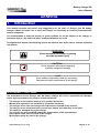
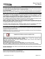
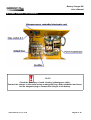
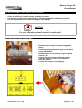
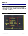
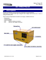
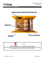
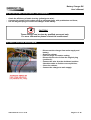
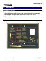
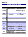
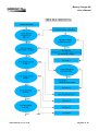
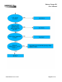
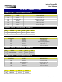
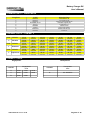
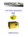
BATTERY CHARGER
RX
USER'S MANUAL
(THIS PAGE WAS INTENTIONALLY LEFT BLANK)
TABLE OF CONTENTS
Table of Contents
· GENERAL.................................................................................................... 4
· 1.
Introduction....................................................................................................... 4
· 2.
Safety instructions and warnings...................................................................... 5
· RX SINGLEPHASE...................................................................................... 7
· 3.
Description........................................................................................................ 7
· 4.
Installation........................................................................................................ 8
· 5.
Operation........................................................................................................ 11
· RX THREEPHASE..................................................................................... 14
· 6.
Description...................................................................................................... 14
· 7.
Installation...................................................................................................... 15
· 8.
Operation........................................................................................................ 18
· TROUBLE SHOOTING GUIDE.................................................................. 21
· SPARE PARTS LIST................................................................................. 24
Battery Charger RX
User's Manual
GENERAL
1.
Introduction
This manual contains instructions and suggestions for the users of Energic plus RX battery
chargers. Before to install, use or repair the charger, it's necessary to read and understand this
manual completely.
It’s recommended to keep the manual in good condition for all the lifetime of the charger. It
should be kept in a dry and clean place, always available to the users.
Throughout this manual, the following special annotations have been used to indicate important
information.
WARNING !
Gives important information regarding
possible personal injury
CAUTION !
Gives important information regarding
possible equipment damage
NOTE
Gives additional information and tips concerning
important procedures and features of the charger
RESPONSIBILITY DISCLAIMER
The manufacturer of the Energic plus RX battery charger will not be responsible for damages
and/or injuries caused by the charger in these situations:
•
•
•
•
•
•
•
•
The charger is not installed properly by a qualified electrician;
Maintenance operations are not done by a qualified electrician;
The charger is not used according to the instructions included in this manual;
The charger is not connected to the correct input supply (see data label on the box);
The battery is damaged during the charge;
The charger has been modified without the authorization of the manufacturer;
Non-original spare parts are used in the charger;
Wrong spare parts are used in the charger.
OWM-040906-RX Version: 02-AB
Page 4 of 25
Battery Charger RX
User's Manual
2.
Safety instructions and warnings
GENERAL
Battery chargers can cause injury or death, or damage to other equipment or property, if the user
does not strictly observe all safety rules and take precautionary actions.
Safe practices must be learned through study and training before using this equipment.
Only qualified personnel should install, use, or service this battery charger.
SHOCK PREVENTION
Bare conductors, or terminals in the output circuit, or ungrounded, electrically-live equipments
can fatally shock a person. To protect against shock, have competent electrician verify that the
equipment is adequately grounded and learn what terminals and parts are electrically HOT.
The body’s electrical resistance is decreased when wet, permitting dangerous current to flow
through the body. Do not work in damp area without being extremely careful. Stand on dry
rubber mat or dry wood and use insulating gloves when dampness or sweat cannot be avoided.
Keep clothing dry.
INSTALLATION AND GROUNDING – Electrical equipment must be installed and mantained in
accordance with all the applicable national and local codes.
A power disconnect switch must be located at the equipment. Check the data label for voltage
and phase requirements. If only 3-phase power is available, connect single-phase equipment to
ONLY TWO WIRES of the 3-phase line.
DO NOT CONNECT the equipment grounding conductor to the third live wire of the 3-phase line
as this makes the equipment frame electrically HOT, which can cause a fatal shock.
If a grounding conductor is part of the power supply cable, be sure to connect it to a properly
grounded switch box or building ground. If not part of the supply cable, use a separate
grounding conductor. Don’t remove a ground prong from any plug. Use correct mating
receptacles. Check ground for electrical continuity before using equipment.
The grounding conductor must be of a size equal to or larger than the size recommended by
Code or this manual.
CHARGING LEADS – Inspect leads often for damage to the insulation. Replace or repair cracked
or worn leads immediately. Use leads having sufficient capacity to carry the operating current
without overheating.
Never extend the charging leads without prior approval of the manufacturer. Extending the
charging leads without prior approval of the manufacturer may cause wrong operation of the
charger and voids the warranty.
BATTERY TERMINALS – Do not touch battery terminals while equipment is operating.
SERVICE AND MAINTENANCE – Shut OFF all power at the disconnect switch or line breaker
BEFORE inspecting, adjusting, or servicing the equipment. Lock switch OPEN (or remove line
fuses) so that the power cannot be turned ON accidentally.
Disconnect power to equipment if it is to be left unattended or out of service.
Disconnect battery from charger.
Measure voltage on capacitors and, if there is any voltage reading, wait 5 minutes before to
proceed.
Keep inside parts clean and dry. Dirt and/or moisture can cause insulation failure. This failure
can result in high voltage at the charger output.
OWM-040906-RX Version: 02-AB
Page 5 of 25
Battery Charger RX
User's Manual
BURN AND BODILY INJURY PREVENTION
The battery produces very high currents when short circuited, and will burn the skin severely if
in contact with any metal conductor that is carrying this current.
Do not permit rings on fingers to come in contact with battery terminals or the cell connectors
on top of the battery.
Battery acid is very corrosive. Alwais wear correct eye and body protection when near batteries.
FIRE AND EXPLOSION PREVENTION
When batteries are being recharged, they generate hydrogen gas that is explosive in certain
concentrations in air (the flammability or explosive limits are 4.1% to 72% hydrogen in air). The
spark-retarding vents help slow the rate of release of hydrogen, but the escaping hydrogen may
form an explosive atmosphere around the battery if ventilation is poor.
The ventilation system should be designed to provide an adequate amount of fresh air for the
number of batteries being charged. This is essential to prevent an explosion.
Always keep sparks, flames, burning cigarettes, and other sources of ignition away from the
battery recharging area. Do not break "live" circuits at the terminals of batteries. Do not lay tools
or anything that is metallic on top of any battery.
To prevent arcing and burning of the connector contacts, be sure the charger is OFF before
connecting or disconnecting the battery. The digital display must be completely OFF.
MEDICAL AND FIRST AID TREATMENT
First aid facilities and a qualified first aid person should be available for each shift for immediate
treatment of electrical shock victims.
EMERGENCY FIRST AID: Call phisician and ambulance immediately and use First Aid techniques
recommended by the American Red Cross.
DANGER: ELECTRICAL SHOCK CAN BE FATAL.
If person is unconscious and electric shock is suspected, do not touch person if he or she is in
contact with charging equipment, battery, charging leads, or other live electrical parts.
Disconnect power at wall switch and then use First Aid.
Dry wood, wooden broom, and other insulating material can be used to move cables, if
necessary, away from person.
IF BREATHING IS DIFFICULT, give oxygen.
IF NOT BREATHING, BEGIN ARTIFICIAL BREATHING, such as mouth-to-mouth.
IF PULSE IS ABSENT, BEGIN ARTIFICIAL CIRCULATION, such as external heart massage.
In case of acid in the eyes, flush very well with clean water and obtain professional medical
attention immediately.
EQUIPMENT WARNING LABELS
Inspect all precautionary labels on the equipment.
Order and replace all labels that cannot be easily read.
OWM-040906-RX Version: 02-AB
Page 6 of 25
Battery Charger RX
User's Manual
RX SINGLEPHASE
3.
Description
Energic plus RX battery chargers have been designed to charge Pb batteries.
These units can convert the AC input voltage to a DC voltage at the correct level, in order to
charge the battery cells.
These are the principal devices included in the charger, available to the user:
•
•
•
•
•
External box;
Led control panel;
Main switch (0-1);
No.2
Cables for battery connection;
No.1
Cable for main supply connection;
OWM-040906-RX Version: 02-AB
Page 7 of 25
Battery Charger RX
User's Manual
4. Installation of the charger
Conditions of use:
•
•
•
Operating temperature:
Storage temperature:
Relative humidity:
5°C to 45°C
-20°C to 60°C
less than 75%
CAUTION !
The charger can be installed by qualified personnel only.
NOTE
This unit operates on 220-230-240 V AC, 50Hz.
Check that the unit's operating voltage is identical to your local power supply.
Check that the unit's maximum input power is available from your power supply.
CAUTION !
To prevent fire or shock hazard, do not expose the unit to rain or moisture.
Do not use the unit in presence of flammable gas, because it can be generate sparks.
CAUTION !
To avoid electrical shock, do not open the cabinet.
Refer servicing to qualified personnel only.
CAUTION !
Allow adeguate air circolation to prevent internal heat buildup.
Do not place the unit near materials that may block the ventilation slots.
Do not install the unit near heat sources such as radiators or air ducts, or in a place
subject to direct sunlight, excessive dust, mechanical vibration or shock.
OWM-040906-RX Version: 02-AB
Page 8 of 25
Battery Charger RX
User's Manual
INTERNAL VIEW OF THE CHARGER
NOTE
Check the efficiency of earth circuitry (yellow/green cable);
Connect the charger to the mains using an adeguate plug, with pushbutton and fuses;
Use an adeguate plug to connect the charger to the battery.
OWM-040906-RX Version: 02-AB
Page 9 of 25
Battery Charger RX
User's Manual
ELECTRICAL INSTALLATION OF THE CHARGER
•
•
•
Check the efficiency of earth circuitry (yellow/green wire);
Connect the charger to the mains using an adeguate plugs, with pushbutton and fuses;
Use an adeguate plug to connect the charger to the battery;
CAUTION !
These settings can be done by qualified personnel only.
For more information please contact the manifacturer.
AC INPUT VOLTAGE ADJUSTMENT
•
•
•
•
•
•
•
OWM-040906-RX Version: 02-AB
Disconnect the charger from main supply and
battery;
Open the cabinet;
Locate the plugs (transformer taps) for AC input
voltage adjustment;
Disconnect the wire A from the original (default
position = 2);
Connect the wire A to the desidered position.
Check the table to find the correct position;
Close the cabinet;
Connect the charger to main supply.
Page 10 of 25
Battery Charger RX
User's Manual
5.
Operation
PRELIMINARY CONTROLS
Inspect the charger completey for loose screws, electrical connections or other damages;
Check that all the ventilation slots are not obstructed to assure proper air flow;
Make sure that the charger is installed as instructed in this manual and in accordance with
any applicable national or local norm.
• Set the main switch
to position “0”;
• Connect the charger to the battery;
•
•
•
When the battery is correctly connected, the LEDs on the control panel start to flash alternately.
LED CONTROL PANEL
OWM-040906-RX Version: 02-AB
Page 11 of 25
Battery Charger RX
User's Manual
START OF THE CHARGE
The charger can be turned on only when the battery is correctly connected.
The charge can start in two ways, depending by the position of the main switch
.
(When the charge is complete, the user may disconnect the battery from the charger to start
working, without turning the main switch
to position “0”. This is not a problem, because the
charger, when the battery is re-connected, will start the charge after a few seconds, to avoid
sparks between contactors ).
If the main switch
is set on “0”, when the battery is connected the LEDs on the control panel flash
alternately.
Now, to start the charge, it’s necessary to set the main switch
to position “1”.
If the main switch
is already in position “1”, the charge starts after about 5 seconds of delay.
When the charge is started, the second LED “CHARGE ON” will flash at frequency of about 1 second.
WARNING !
When the charge is started, check that the LED “CHARGE ON” is flashing at
frequency of about 1 second. This control is useful to be sure that the electronic
control is working correctly.
WARNING !
ENERGIC Plus RX chargers are programmed to do a complete cycle of charge,
however it’s recommended to survey the operations when the battery must remain
connected to the charger for more than 12 hours (example: week-ends)
CHARGE OPERATIONS
NOTE
The operations described in this chapter are done by
ENERGIC Plus RX chargers automatically.
OWM-040906-RX Version: 02-AB
Page 12 of 25
Battery Charger RX
User's Manual
CHARGE CYCLE
The current of charge follows the Wa curve, as described in the DIN 41774 norm, while the LED
“CHARGE ON” continuously flashes.
After some hours, depending by the conditions of the battery, when the battery’s voltage reaches the
value of “gassing” (2,4 Volt per cell), the LED “FINAL CHARGE” starts to flash and the charge
continues.
After three hours the charge is completed, and the LED “STOP” is turned on. At this point the
equalization cycle starts.
If the charge is not normally completed within 12 hours, the electronic control stops the charger, the LED
“EMERGENCY STOP” is turned on and the equalization cycle is excluded. If this happens it’s
necessary to check the conditions of charger and battery before starting another charge cycle.
EQUALIZATION
When a battery is new, all the cells are virtually in the same condition. After the first cycle of chargedischarge, it's possible to measure small differences of voltage between the cells. These little
differences between cells, in the next charge-discharge cycles, are more and more emphasized. This
process reduces the performance of the battery and its life.
The EQUALIZATION function, performed by ENERGIC Plus RX chargers, has been developed to keep
all the cells of the battery at the same level, even after years of continuous work.
Equalization is performed by giving extra charge cycles of 30 minutes every 15,5 hours.
During extra charge cycles the LEDs “ FINAL CHARGE” and “STOP” flash alternately.
The equalization function starts with a pause of 15,5 hours, it is then performed when the battery
remains connected to the charger for more than about 24 hours (example: week-ends).
The electronic control of the charger measures only the time of effective charge so, even after one or
more main supply black-outs, the charge cycle re-starts from the point of interruption.
The electronic control is reset only when the battery is disconnected.
END OF CHARGE
When the battery is completely charged the charger is turned off and the LED “STOP” is turned on.
WARNING !
Before disconnecting the battery, check it is not being charged. If it is charging
turn off the charger using the main switch, to avoid sparks between connectors.
OWM-040906-RX Version: 02-AB
Page 13 of 25
Battery Charger RX
User's Manual
RX THREEPHASE
6.
Description
Energic plus RX battery chargers have been designed to charge Pb batteries.
These units can convert the AC input voltage to a DC voltage at the correct level, in order to
charge the battery cells.
These are the principal devices included in the charger, available to the user:
•
•
•
•
•
External box;
Led control panel;
STOP pushbutton;
No.2
Cables for battery connection;
No.1
Cable for main supply connection;
OWM-040906-RX Version: 02-AB
Page 14 of 25
Battery Charger RX
User's Manual
7. Installation
Conditions of use:
• Operating temperature:
• Storage temperature:
• Relative humidity:
5°C to 45°C
-20°C to 60°C
less than 75%
CAUTION !
The charger can be installed by qualified personnel only.
NOTE
This unit operates on threephase AC input, 380 Vac, 50Hz.
Check that the unit's operating voltage is identical to your local power supply.
Check that the unit's maximum input power is available from your power supply.
CAUTION !
To prevent fire or shock hazard, do not expose the unit to rain or moisture.
Do not use the unit in presence of flammable gas, because it can be generate sparks.
CAUTION !
To avoid electrical shock, do not open the cabinet.
Refer servicing to qualified personnel only.
CAUTION !
Allow adeguate air circolation to prevent internal heat buildup.
Do not place the unit near materials that may block the ventilation slots.
Do not install the unit near heat sources such as radiators or air ducts, or in a place
subject to direct sunlight, excessive dust, mechanical vibration or shock.
OWM-040906-RX Version: 02-AB
Page 15 of 25
Battery Charger RX
User's Manual
INTERNAL VIEW OF THE CHARGER
NOTE
Check the efficiency of earth circuitry (yellow/green cable);
Connect the charger to the mains using an adeguate plug, with pushbutton and fuses;
Use an adeguate plug to connect the charger to the battery.
OWM-040906-RX Version: 02-AB
Page 16 of 25
Battery Charger RX
User's Manual
ELECTRICAL INSTALLATION OF THE CHARGER
•
•
•
Check the efficiency of earth circuitry (yellow/green wire);
Connect the charger to the mains using an adeguate plugs, with pushbutton and fuses;
Use an adeguate plug to connect the charger to the battery.
CAUTION !
These settings can be done by qualified personnel only.
For more information please contact the manifacturer.
AC INPUT VOLTAGE ADJUSTMENT
•
•
•
•
•
•
•
OWM-040906-RX Version: 02-AB
Disconnect the charger from main supply and
battery;
Open the cabinet;
Find the plugs for tension setting;
Disconnect the wire A from the original plug
(position 2);
Connect the wire A to the desidered position.
Check the table to find the correct position;
Close the cabinet;
Connect the charger to main supply.
Page 17 of 25
Battery Charger RX
User's Manual
8. Operation
PRELIMINARY CONTROLS
•
•
•
Inspect the charger completey for loose screws, electrical connections or other damages;
Check that all the ventilation slots are not obstructed to assure proper air flow;
Make sure that the charger is installed as instructed in this manual and in accordance with
any applicable national or local norm.
LED CONTROL PANEL
OWM-040906-RX Version: 02-AB
Page 18 of 25
Battery Charger RX
User's Manual
START OF THE CHARGE
The charger can be turned on only when the battery is correctly connected.
WARNING !
When the charge is started, check that the LED “CHARGE ON” is flashing at
frequency of about 1 second. This control is useful to be sure that the electronic
control is working correctly.
CHARGE OPERATIONS
When the battery is connected, the charger turns on automatically in 5 seconds and the LED
“CHARGE ON” starts to flash.
If the main supply is not present, all the control LEDs (except the “BATTERY CONNECTION”
LED) starts to flash alternately.
START OF THE CHARGE
When the charge is started, check that the LED “CHARGE ON” is flashing at frequency of about
1 second. This control is useful to be sure that the electronic control is working correctly.
Energic Plus RX chargers are programmed to do a complete cycle of charge, however it’s
recommended to survey the operations when the battery must remain connected to the charger
for more than 12 hours (example: week-ends)
OWM-040906-RX Version: 02-AB
Page 19 of 25
Battery Charger RX
User's Manual
CHARGE OPERATIONS
•
The maximum time allowed to reach the gassing voltage is 12 hours. If the battery doesn’t
reach the gassing voltage within 12 hours the charger stops and the LED “EMERGENCY
STOP” lights on and the EQUALIZATION is excluded.
•
When the battery reaches the gassing voltage, the LED “FINAL CHARGE” starts to flash,
together with the LED “CHARGE ON”, and the charge continues for 3 hours.
•
If the battery is disconnected, the charger turns off in 3 seconds and the charge process is
completely reset.
•
When a battery is re-connected, the charger turns on automatically and the charge starts
from the beginning.
•
If, during the charge or equalization, there are one or more black-outs of the mains, the
microprocessor keeps in memory the state of the charge and, when the power supply is
available again, the charge re-starts from the exact point of interruption.
•
When the charge is complete, the charger goes in stand-by mode for 15hours 30minutes,
before to proceed with the equalization, therefore the equalization will be executed only when
the charger remains connected for more than 24hours (normally in the weekend).
•
The equalization consists in 4 small charge cycles (30 minutes long), with 15hours and 30
minutes of interval between each cycle. During extra charge cycles the LEDs “ FINAL
CHARGE” and “STOP-100%” flash alternately.
NOTE
The operations described in this chapter are done by ENERGIC Plus RX chargers
automatically.
END OF CHARGE
When the battery is completely charged the charger is turned off and the LED “STOP – 100%”
continues to flash.
WARNING !
Before disconnecting the battery, make sure that it is not being charged. If it is being
charged, turn off the charger using the STOP pushbutton, to avoid sparks between
connectors.
OWM-040906-RX Version: 02-AB
Page 20 of 25
Battery Charger RX
User's Manual
TROUBLE SHOOTING GUIDE
SYMPTOM
POSSIBLE CAUSES
ACTION
1 Battery not connected properly.
Check battery connectors/harness.
Charger does not
2
react to battery
being connected,
A
and LED control
3
panel remains
4
OFF.
Charger has been connected to
forklift motor connector.
Disconnect forkift motor and
connect battery.
Output cables reversed.
Check charger, connectors and battery
polarities. Output fuse is probably blown.
Bad control board connection.
Check board connectors (green).
Bad control board.
Replace control board.
Output fuse blown.
Replace output fuse and adjust AC input
setting.
1
AC input is absent.
Check AC input voltage on each phase.
Check AC input connections.
Check AC disconnect switch and fuses.
2
Bad contactor.
Replace contactor.
Wrong AC input settings.
Adjust AC input settings to higher voltage.
One or more cells are shorted.
Repair battery.
1
Wrong AC input settings.
Adjust AC input settings to lower voltage.
2
One AC phase is absent.
Check AC input voltage on each phase.
3
One or more diodes blown.
Replace rectifier.
4
Bad contactor.
Replace contactor.
1
Bad location.
Install the charger in proper location.
2
Ventilation slots obstructed.
Remove objects which may obstruct slots.
Wrong AC input settings.
Adjust AC input settings to higher voltage.
4
Bad or loose power wirings.
Check and thighten all power wirings.
5
Transformer burned.
Replace transformer.
1
Bad contactor.
Replace contactor and freewheeling diode.
2
One or more diodes shorted.
Replace rectifier.
1
Wrong AC input settings.
Adjust AC input settings to lower voltage.
2
Battery capacity too low.
Replace battery.
1
Wrong AC input settings.
Adjust AC input settings to higher voltage.
5
Output current is
B
absent.
All the control
LEDs flash
alternately.
C
1
Output current is
D
too high.
2
Output current
is too low.
Charger
smells hot.
Charger
too noisy
Battery has low
S.G. and/or
doesn't
last full shift .
Battery
temperature
too high.
E
F 3
G
H
2 Battery power demand too high.
I
Consider purchasing bigger Ah battery.
3
Insufficient cool down time.
Increase cool down time before/after
charging.
4
Automatic stop doesn't work.
Check and replace board and/or contactor.
OWM-040906-RX Version: 02-AB
Page 21 of 25
Battery Charger RX
User's Manual
OWM-040906-RX Version: 02-AB
Page 22 of 25
Battery Charger RX
User's Manual
OWM-040906-RX Version: 02-AB
Page 23 of 25
Battery Charger RX
User's Manual
SPARE PARTS LIST
COMMON PARTS – SINGLEPHASE CABINET S
POSITION
CODE
DESCRIPTION
1-S
2-S
3-S
4-S
5-S
6-S
7-S
8-S
9-S
10-S
0203340
0203341
0203129T
RLCBSRE-06-01
0201321
0201829
0201828
0100999
100001
1011CA01
Base RE box S
Cover RE box S
Printcard external plate RX
Printcard support (x4)
Main switch 0-1
Cable strain relief
Cable strain relief
Hand grip
Output fuse holder
Plastic feet RE (x4)
VARIABLE PARTS – SINGLEPHASE CABINET S
POS.
DESCR.
12-25
11-S
12-S
13-S
Rectifier
Printcard 567SCE
Output fuse
0201911
0302761
0201062
24-20
24-25
24-30
0201903 0202032 0202032
0302762 0302762 0302762
0201062 0201062 0201062
COMMON PARTS – SINGLEPHASE CABINET A
POSITION
CODE
DESCRIPTION
1-A
2-A
3-A
4-A
5-A
6-A
7-A
0203345
0203346
0203129T
RLCBSRE-06-01
0201321
100001
1011CA01
Base RE box A
Cover RE box A
Printcard external plate RX
Printcard support (x4)
Main switch 0-1
Output fuse holder
Plastic feet RE (x4)
VARIABLE PARTS – SINGLEPHASE CABINET A
POS.
DESCR.
24-40
24-50
24-60
8-A
9-A
10-A
Rectifier
Printcard 567SCE
Output fuse
0202033
0302762
0201063
0201914
0302762
0201064
0202016
0302762
0201065
COMMON PARTS – SINGLEPHASE CABINET B
POSITION
CODE
DESCRIPTION
1-B
2-B
3-B
4-B
5-B
6-B
7-B
0203370
0203374
0203129T
RLCBSRE-06-01
0201321
100001
1020CA01
Base RE box B
Cover RE box B
Printcard external plate RX
Printcard support (x4)
Main switch 0-1
Output fuse holder
Plastic feet RE (x4)
VARIABLE PARTS – SINGLEPHASE CABINET B
POS
8-B
9-B
10-B
DESCR.
Rectifier
Printcard 567SCE
Output fuse
48-60
0202016
0302764
0201065
OWM-040906-RX Version: 02-AB
48-80
0202017
0302764
0201066
Page 24 of 25
Battery Charger RX
User's Manual
COMMON PARTS – THREEPHASE
POSITION
CODE
DESCRIPTION
1
2
3
4
5
6
7
8
9
0203370
0203374
0203125
RLCBSRE-06-01
203141
0203999
100001
1020CA01
0203262
Base RE box B
Cover RE box B
Printcard external plate RE
Printcard support (x4)
Pushbutton 0-1
Varistor 275V
Output fuse holder
Plastic feet RE (x4)
Contactor
VARIABLE PARTS – CABINET C
POS.
DESCR.
24-80
24-100
36-60
36-80
36-100
40-50
0202022
0202023
0202021
0202022
0202023
0202021
Rectifier
10
POS.
40-60
40-80
48-50
48-60
48-80
48-100
72-60
0202021
0202022
0202021
0202021
0202022
0202023
0202021
DESCR.
24-60
24-80
24-100
36-60
36-80
36-100
40-50
0202752
0202752
0202752
0202753
0202753
0202753
02027535
Printcard
11
POS.
12
24-60
0202021
40-60
40-80
48-50
48-60
48-60
48-100
72-60
02027535
02027535
0202754
0202754
0202754
0202754
0202755
DESCR.
24-60
2480
24-100
36-60
36-80
36-100
40-50
0201065
0201066
0201067
0201065
0201066
0201067
0201064
Output fuse
40-60
40-80
48-50
48-60
48-80
48-100
72-60
0201065
0201066
0201064
0201065
0201066
0201067
0201065
CABINETS TABLE
Singlephase
Threephases
Singlephase
Units
CABINET
S
24/20
24/25
24/30
A
24/40
24/50
24/60
B
48/60
48/80
OWM-040906-RX Version: 02-AB
CABINET
Threephase
Units
B
ALL MODELS
Page 25 of 25