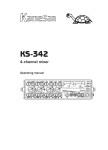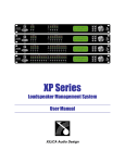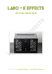
1
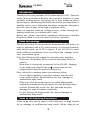
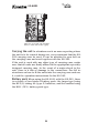
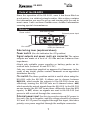
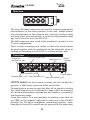
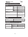
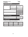
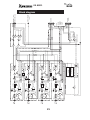
KS-6001
Sub-mixer
Operating manual
L
PF L
C R
L
PF L
C R
L
PF L
C R
FD
LINK
200
200
A-B
P-48
Dy-M
LINE
+4
-30
-20
-70
P-48
PF L
C R
20 0
A-B
A-B
PEAK
L
FD
LINK
Dy-M
LINE
PEAK
+4
-30
-20
-70
P-48
Dy-M
LINE
PEAK
+4
-30
-20
-70
20 0
A-B
P-48
Dy-M
LINE
PEAK
+4
-30
-20
-70
POWER
KS-6001
Introduction
Thank you for your purchase of the Kamesan KS - 6001. This sub
audio mixer provides a flexible and powerful solution to your
portable mixing needs, accepting up to four balanced microphone inputs, and mixing them into two before passing them to
another mixer via a dedicated hardware connector integrated
into the case design, or through a separate cable.
Power is supplied from an outside source, either through the
mating connector or a dedicated DC inlet.
Before use, please read these operation instructions carefully,
then keep them in a secure place for future reference.
Notes and warnings
The KS - 6001 may be used with the Kamesan KS -432 mixer, or
may be operated with a DC power source or external rechargeable battery pack (up to 16 V output). If the KS - 6001 is used
under different conditions, there is a risk of fire, damage to the
unit, or personal injury.
Note the following with regard to external power supplies:
Make sure the polarity of the external powering device is
correct.
Make sure it is properly connected to the KS-432. Damage
to the units may result if the joint connectors are not
properly fitted and the power is turned on.
Also, follow the common-sense precautions below:
Do not allow liquids to come into contact with the unit
or be spilled inside. Should this occur, fire, damage or
malfunction may result.
Make sure that no metal objects or easily inflammable
substances inadvertently get inside the unit through holes
or slots. Should this occur, fire, the unit may become
damaged or start to behave erratically.
Do not attempt to disassemble the unit as damage or
malfunction may result.
Notes on the Operating Environment
Avoid using this unit in places with high heat or high humidity as damage or malfunction may result. When using in an
3
KS-6001
exceptionally cold environment, battery service life may be
shortened, and there may be a drop in performance. If at all
possible, use this unit in the temperature range as indicated in
the specifications.
When connecting this unit to external devices, be sure to read
all related operation manuals and connect the devices correctly
to each other. If there are mistakes in the connections, it is possible that either the KS - 6001 or the other unit(s) will be damaged.
In the event that smoke or odors come from the unit, turn off
the power and remove all batteries and external power supply
sources at once. Contact your dealer or service representative.
In the event of damage or injury caused by accidents, improper
operation or functioning, the proper course of action shall be
determined according to our service regulations. Please note
that we cannot be responsible in any way for any loss of pre-recorded material.
4
KS-6001
Attaching the KS-6001 as a sub mixer
Locking pins (bottom) and sockets (top) These locking
pins and sockets locate the KS - 6001 in position when connecting it to another unit. They are secured and released with the
locking levers
Multipurpose connector This multipurpose connector carries
signals to and from the KS - 6001 to the other unit. It is usually
recessed, but may be released by sliding the small silver lever
(marked RELEASE) using a small screwdriver or similar. Once
the connector has been released, it is locked in the “Up” position but may be recessed again by sliding the release lever and
pressing down the connector until it locks at the recessed position.
Locking levers
Multipurpose connector under cover
Locking pins/sockets
Connector cover if the KS - 6001 is being used as a standalone unit, you should always replace the cover and retain it in
place with the screws provided. Keep the cover plate and the
screws whenever the KS - 6001 is attached to another unit.
Note:
Large and small cushions that enable use with the KS-342
carrying case are supplied with this unit. These cushions are used
with the carrying case as shown in the accompanying illustration.
The large cushion should be used when the BP-3/8 (AA battery
pack) is used. The smaller cushion is used when using the BH-1
(NP-1 battery pack).
5
KS-6001
������
�������
�������
Side view of KS-342 with KS-6001
fitted, in case with cushion (gray)
Carrying the unit In situations such as news reporting where
the unit is to be carried during use, we recommend that the KS 342 carrying case be used. It can be attached to your belt on
the carrying case and used together with the KS -342.
If the unit is used with any other type of carrying case, make
sure that all units are firmly affixed in the appropriate speciallydesigned carrying case. In the event of a major shock to the
unit, there is a risk of damage to the connectors. For full instructions on how to fit the units into the carrying case and use
it, read the operation instructions for the KS -342.
Battery pack When using the KS - 6001 with the KS -342, there
is a choice of two kinds of battery pack: the larger type being
the BP-3/8, taking AA (type 3) batteries, and the smaller being
the BH-1 (NP-1) battery pack type.
6
KS-6001
Parts of the KS-6001
Since the operation of the KS - 6001, once it has been fitted as
a sub-mixer, is a relatively simple matter, this section contains
the information you need to get up and running with the unit in
most cases. Later sections contain more detailed information
covering special circumstances.
Side view
Power switch
Side locking lever
7
POWER
1
6
2
5
3
BUS MIX
AUX
(MONI)
OFF
Mix switch
External power input
MIX OUT
(-20dBs)
4
CN Pin Assign
1.FG
2.Lch H
3.Lch C
4.Rch H
5.Rch C
6.+10
~ 16V
7.0V
Signal outputs and power
multi-pin connecvor
Side locking lever (explained above)
Power switch (the dot indicates the ON position)
Signal outputs and power multi-pin connector The mixer
outputs are made at a level of –20 dBs and are balanced lowimpedance.
Attach only suitable power supplies or battery packs as described here (between 16 and 20 V DC).
Only use connectors supplied or approved by Kamesan. in the
event of any doubt, please contact Kamesan or an appointed
distributor directly.
Mix switch The three-position switch is useful when using the
KS - 6001 with the KS -342. It allows you to choose between
BUS MIX: which sends the outputs to the KS -342’s buss mix,
effectively turning the KS -342 into an 8-channel mixer. AUX,
which sends the mixed signals from the KS - 6001 to the KS -342
as aux inputs (the KS -342 treats these differently from the BUS
inputs); or OFF, where no signals are sent to the KS -342 (but
power is still received through the connector).
External power input Use this to provide external DC power to
the unit—the tip is negative, and the voltage should be between
10 V and 16 V. If power is supplied through this input, this takes
priority over power supplied through the multipin connector.
7
KS-6001
Side view
The four XLR male connectors are used to connect appropriate
microphones (or line-level sources) to the unit. Always ensure
that microphones or line sources are correctly selected using
the front panel selection switch, in order to avoid possible damage to the sources or to the KS - 6001.
The XLR connectors are wired in the standard 1=ground, 2=hot,
3=cold configuration.
There is also a locking lever visible on this side which should
be used together with its counterpart on the other side when attaching or detaching the KS - 6001 to or from another unit.
Front view
LCF/PFL switch (x 4)
Output bus
assignment (x4)
L
PF L
C R
L
PF L
C R
L
Fader link (x 2)
PF L
C R
FD
LINK
200
Dy-M
LINE
200
20 0
A-B
A-B
PEAK
+4
-30
-20
-70
P-48
PF L
C R
POWER
FD
LINK
A-B
P-48
L
Power
indicator
Dy-M
LINE
PEAK
+4
-30
-20
-70
P-48
Dy-M
LINE
Input selector (x 4)
PEAK
+4
-30
-20
-70
20 0
A-B
P-48
Dy-M
LINE
PEAK
+4
-30
-20
-70
Master faders
Channel fader (x 4) Peak indicator (x 4)
Input trim control (x 4)
LCF/PFL switch Use this control to sweep the low-cut filter frequency (–12dB/octave) between 20Hz and 200Hz.
Though there is no way to turn this filter off, in practice, setting
the cutoff frequency to 20 Hz has the same effect as turning it
off, as most microphone systems are not sensitive to sounds in
that frequency range.
Press this control (it is non-latching) to perform a pre-fade listen (PFL) on the channel (only when connected to the KS -342,
through the KS -342’s headphone monitoring system). More
than one of these PFL controls can be pressed at the same time,
8
KS-6001
but in this case, the level and left VU meter indication (on the
KS -342) will be lower than the actual values.
Channel fader Turn clockwise to increase, and counterclockwise to decrease, the output level of this channel.
Output bus assignment Use this to send the output of the
channel to the left (L), right (R) or center (C – left and right) output busses.
Input selector Use this to select between:
P48 Condenser microphones requiring +48V phantom powering
Dy-M Dynamic microphones
LINE Line-level sources
A-B - A-B type microphones
Ensure that only microphones corresponding to the selection
are connected to the appropriate inputs, otherwise damage may
occur to the KS-6001 and to the microphones.
PEAK indicator Shows when the pre-fader, post-gain signal is
more than 28 dB above the optimum level.
Input trim control Used to adjust the level of the signal fed
to each channel. The amount of trim depends on the input setting: the blue figures indicate line-level settings, and the white
figures indicate microphone levels.
Channel fader link switches (FD LINK) When these switches
are on (in the right position), the even-numbered fader controls
the levels of both its own channel and the odd-numbered channel to its left.
L & R master level controls Push to extend these controls
and push again to recess them. These affect the level of the
signal fed from the unit to the KS -342 through the MIX OUT
connector.
Power and status indicator This indicator serves two purposes. Firstly, it acts as a power indicator, showing when power is
supplied to the unit. Secondly, the color of the indicator shows
the current setting of the output bus as set by the side rotary
control (TO 342). Green indicates the bus mix is active, yellow
indicates AUX (for monitoring) and red indicates off, or a power
supply below 9V.
9
KS-6001
If this (and/or the equivalent indicator on the KS -342) flashes
read, you should immediately replace the batteries.
Using the unit—some notes
Before starting to use the KS - 6001, or connecting any equipment to it, make sure that the unit’s power switch is turned
OFF.
Before actually connecting microphones or other sources to it,
make sure that the input selector switch is turned to the appro priate position for each channel. There is a risk of serious damage to equipment if the wrong selection is made!
Make the multi-pin output/power connection.
Turn on the power when the connections have been made.
The unity gain position for each fader is around the 2 o’clock
mark, as shown by a slightly thicker line at this position.
Typically, you should set the individual channel faders to this
position, the master controls to their maximum, and then adjust the trim controls so that the VU meters on the main mixer
to which the KS - 6001 is connected show 0 dB on a nominal signal input. This provides sufficient headroom without forcing the
head amp to work too hard.
10
KS-6001
Technical notes and specifications, etc.
Inputs
Input level (4 channels)
Input impedance
MIC
– 70 to –30 dBs (balanced
inputs)
LINE
–20 to +4 dBm (balanced
inputs)
MIX
1.2 kΩ
LINE
600 Ω
Headroom
> 30 dB (pre-fader)
Phantom powering
either 48 V (maximum
current of 8 mA) or A-B
12 V (maximum current of
40 mA)
High-pass filter
–12 dB/octave, sweepable
cutoff between 20 Hz and
200 Hz
Outputs
Output level
–20 dBs (from a 7-pin Cannon connector,
electrically balanced, low-impedance output
Maximum output
+8 dBs (into 600Ω)
Performance
Figures measured when connected to KS -342.
Frequency response
50 Hz to 15 kHz, < ±1.0 dB
Signal-to-noise ratio
MIC at –70
>55 dB (30 kHz LPF/RMS)
LINE at +4
>68 dB (30 kHz LPF/RMS)
Total harmonic distortion
LINE < 0.5% (50 Hz thru 15kHz, nominal level)
MONI < 0.5% (50 Hz thru 15kHz, nominal level)
11
KS-6001
Electrical characteristics
Figures measured when connected to KS -342
External power supply
Between +10 V and
+16 V DC (maximum
power 0.2A)
Supplied through 7-pin
Cannon connector or
through dedicated DC
input
Typical power consumption
105 mA
Battery life (KS-342 and KS-6001 used together)
> 2 h (manganese cells)
> 3 h (alkaline cells)
> 6 h (NP-1 pack)
Battery life ((KS-KS-6001 used as standalone)
> 2 h (manganese cells)
> 3 h (alkaline cells)
> 6 h (NP-1 pack)
Physical specifications
Dimensions (w x d x h)
215 x 170 x 40 (mm)
8.5 x 6.7 x 1.6 (in)
Weight
1.1 kg (2.4 lb)
Connector pinout
The XLR-7-11C connector used to provide power and to carry
out the master bus signals is wired as follows:
1
FG
5
R-ch —
2
L-ch +
6
DC IN +
3
L-ch —
7
DC 0V
4
R-ch +
12
CH4
INPUT
CH3
INPUT
CH2
INPUT
CH1
INPUT
(XLR-3)
(XLR-3)
(XLR-3)
(XLR-3)
A-B 12
LINE
P-48
Dy-M
A-B 12
LINE
P-48
Dy-M
13
A-B 12
LINE
P-48
Dy-M
INPUT SEL.
P
INPUT SEL.
P
GAIN
HA
MIC -70~-30
LINE -20~+4
H.P.F.
( 20~200Hz )
MIC -70~-30
LINE -20~+4
H.P.F.
( 20~200Hz )
MIC -70~-30
LINE -20~+4
H.P.F.
( 20~200Hz )
MIC -70~-30
LINE -20~+4
H.P.F.
( 20~200Hz )
POWER
GAIN
Peak
GAIN
Peak
HA
LINE
A-B 12
GAIN
Peak
HA
Peak
HA
P-48
Dy-M
INPUT SEL.
P
INPUT SEL.
P
FD
FD
FD
FD
R
C
L
OUTPUT SEL
LINK
R
C
L
OUTPUT SEL
R
C
L
OUTPUT SEL
LINK
R
C
L
OUTPUT SEL
+B
POWER/OUT
Power Regulator
P-48V (option)
DC-DC Converter
A-B12V
DC-DC Converter
PFL
BA
LINK
PFL
BA
PFL
BA
LINK
PFL
BA
BA
MIX
MIX
BA
BAL
BA
BAL
to SS342 OUTPUT SELECT
OFF
R AUX IN
R MIX BUS
OFF
L AUX IN
L MIX BUS
PFL TALLY
L-SUB MIX
R-SUB MIX
EXT I/O TALLY (HA)
PFL
INS I/O
R MAS
L MAS
AUX L
AUX R
PFL
(to SS342)
EXT. I /O
EXT. I /O
(+9~16V)
EXT.DC IN JACK
MIX OUT (-20dBs)
EXT.DC IN (+9~16V)
MIX IN
MIX OUT
MONI OUT
AUX IN
PFL IN
P-48V
EXT I/O
POWER
(XLR7-32)
KS-6001
Block diagram
PFL TALLY
R-MIX BUS
PFL
L-MIX BUS
KS-6001
About Kamesan
Sigma Systems Engineering was started in 1972 to develop and design
professional mixers for studio and remote broadcast applications.
Today, following the “slow and steady” principle of the tortoise, we
have built up our sales and our reputation to the extent that we now
enjoy 95% of the Japanese portable mixer market.
We have concentrated on two or three main areas in our design philosophy: compactness, in an industry which was traditionally dominated
by large, heavy equipment; ease of use, since time is always of the essence in the environments where our products are used; and quality,
to match the needs that today’s broadcasters require.
Our head office is in Shinjuku, Tokyo, and as a small company, we are
happy to listen to the ideas for product improvement suggested by you,
the customers and users of our equipment.
Making steady progress (like a tortoise, but maybe a little faster!), we
hope to meet your requirements, now and in the future.
Visit both of our Web sites at http://www.kamesan.co.jp and
http://www.kamesan.info in order to find out more about what we’re
doing, and to let us know what you are doing with Kamesan products.
14
Sigma Systems Engineering Co. Ltd.
3-5-2 Okubo
Shinjuku-ku
Tokyo 169- 0072
JAPAN
Tel: +81 3 3204 2611
Fax: +81 3 3204 2250
e-mail: [email protected]