1
AX6700S/AX6600S/AX6300S/AX3800S/AX3600S/AX2400S
Troubleshooting Guide
AX36S-T001X-E0
Relevant products
This manual applies to the models in the AX6700S, AX6600S, AX6300S, AX3800S, AX3600S, and AX2400S series of switches.
Export restrictions
In the event that any or all ALAXALA products (including technologies, programs and services) described or contained herein are controlled
under any of applicable export control laws and regulations (including the Foreign Exchange and Foreign Trade Law of Japan and United States
export control laws and regulations), such products shall not be exported without obtaining the required export licenses from the authorities
concerned in accordance with the above laws.
Trademarks
Cisco is a registered trademark of Cisco Systems, Inc. in the United States and other countries.
Ethernet is a registered trademark of Xerox Corporation.
Internet Explorer is either a registered trademark or trademark of Microsoft Corporation in the United States and other countries.
IPX is a trademark of Novell, Inc.
Microsoft is either a registered trademark or trademark of Microsoft Corporation in the United States and other countries.
Octpower is a registered trademark of NEC Corporation.
RSA and RSA SecurID are trademarks or registered trademarks of RSA Security Inc. in the United States and other countries.
sFlow is a registered trademark of InMon Corporation in the United States and other countries.
UNIX is a registered trademark of The Open Group in the United States and other countries.
VitalQIP and VitalQIP Registration Manager are trademarks of Alcatel-Lucent.
VLANaccessClient is a trademark of NEC Soft, Ltd.
VLANaccessController and VLANaccessAgent are trademarks of NEC Corporation.
Windows is a registered trademark of Microsoft Corporation in the United States and other countries.
Other company and product names in this document are trademarks or registered trademarks of their respective owners.
Reading and storing this manual
Before you use the equipment, carefully read the manual and make sure that you understand all safety precautions.
After reading the manual, keep it in a convenient place for easy reference.
Notes
Information in this document is subject to change without notice.
Please note that the actual product might differ from how it is depicted in output examples and figures.
Editions history
December 2012 (Edition 15) AX36S-T001X-E0 (SOFT-AM-006_R15)
Copyright
All Rights Reserved, Copyright(C), 2005, 2012, ALAXALA Networks, Corp.
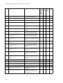
History of Amendments
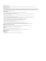
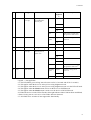
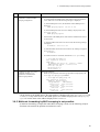
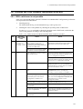
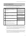
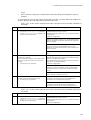
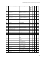
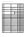
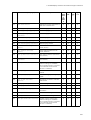
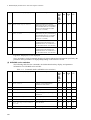
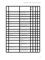
[Edition 14]
Summary of amendments
Item
Changes
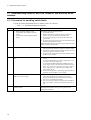
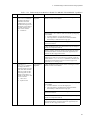
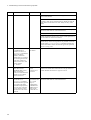
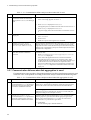
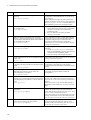
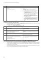
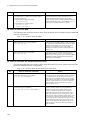
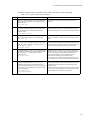
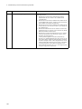
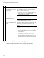
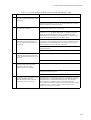
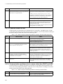
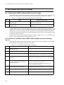
Failure analysis for the AX3800S, AX3600S, and
AX2400S series
• A description of AX3830S-44X4QW was added.
Loop connector specifications
• A description of 40GBASE-SR4 loop connector specifications
was added.
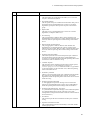
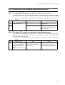
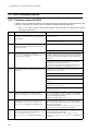
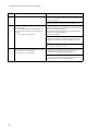
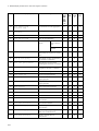
[Edition 13]
Summary of amendments
Item
Changes
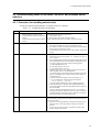
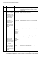
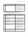
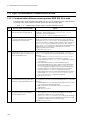
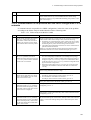
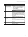
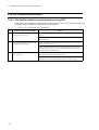
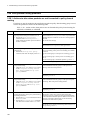
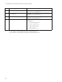
Returning to administrator mode from configuration
command mode is not possible
• This subsection was added.
Stack configuration problems
• This subsection was added.
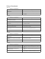
Communication failures in filters and QoS
configurations
• Descriptions of policy-based routing and policy-based
switching were added.
Policy-based routing problems
• This subsection was added.
Policy-based switching problems
• This subsection was added.
Action to be taken when a MAC address table resource
shortage occurs
• A description of policy-based switching was added to Table
4-3 How to delete MAC address table entries.
Obtaining failure information
• A description of stacks was added.
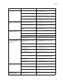
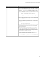
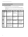
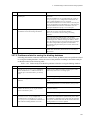
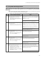
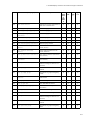
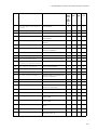
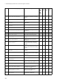
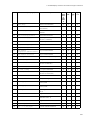
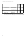
[Edition 12]
Summary of amendments
Item
Changes
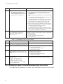
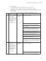
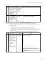
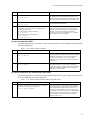
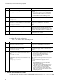
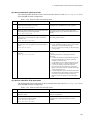
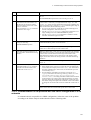
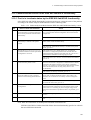
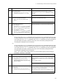
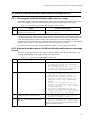
Failure analysis for the AX3800S, AX3600S, and
AX2400S series
• A description of AX3800S series switches was added.
Communication is not possible in IPv4 PIM-DM
networks
• This subsection was added.
Multicast data is forwarded twice in an IPv4 PIM-DM
network
• This subsection was added.
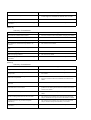
[Edition 11]
Summary of amendments
Item
Changes
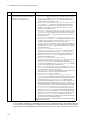
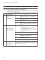
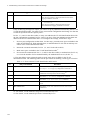
Failure analysis for the AX3600S and AX2400S series
• A description of AX3600 and AX2400S series switches was
added.
Failures occurring when the Ring Protocol
functionality is used
• A description of the multi-fault monitoring functionality was
added.
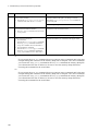
Communication is not possible or is disconnected
• The description was changed in accordance with the addition
of VRF support in AX3600S and AX2400 series switches.
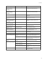
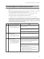
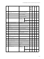
Item
Changes
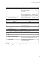
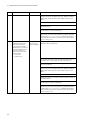
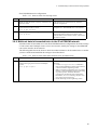
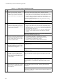
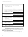
Communication is not possible or is disconnected
• The description was changed in accordance with the addition
of VRF support in AX3600S and AX2400 series switches.
Creating loop connectors
• This subsection was added.
Detailed display contents of the "show tech-support"
command
• Commands were added to the detailed description.
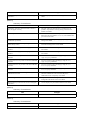
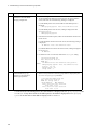
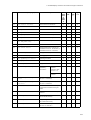
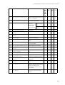
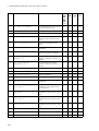
[Edition 10]
Summary of amendments
Item
Changes
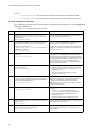
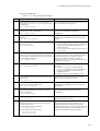
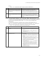
IPv4 network communication failures
• Actions to be taken when using DHCP snooping were added.
IPv6 DHCP relay communication problems
• This subsection was added.
IPv6 multicast communication problems in VRF
• This subsection was added.
IPv6 multicast communication problems in an
extranet
• This subsection was added.
Problems due to the redundant configuration of the
NIF
• This section was added.
Access list logging problems
• This section was added.
DHCP snooping problems
• This section was added.
Detailed display contents of the "show tech-support"
command
• Commands were added to the detailed description.
[Edition 9]
Summary of amendments
Item
Changes
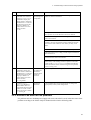
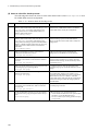
Login from a remote terminal is not possible
• Actions to be taken when a user cannot log in were added.
Login authentication using RADIUS/TACACS+ is
not possible
• Actions to be taken when a user cannot log in to the Switch
were added.
Command authentication using RADIUS/TACACS+
and local is not possible
• Items to be checked were added.
• Actions to be taken when all commands are restricted were
added.
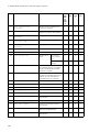
Actions to be taken for 100BASE-FX/1000BASE-X
problems
• Actions to be taken for 100BASE-FX were added.
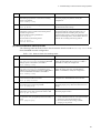
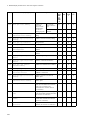
Problems that occur during IPv4 multicast
communication in the extranet
• This subsection was added, and actions to be taken when a
problem occurs during IPv4 multicast communication in the
extranet were added.
Communication is not possible or is disconnected
• Items to be checked for the optional license OP-NPAR were
added.
No IPv6 routing information exists in the VRF
• This subsection was added, and a description of the failure
analysis method for the option license OP-NPAR was added.
Communication is not possible with uplink
redundancy
• This subsection was added, and a description of the failure
analysis method with uplink redundancy was added.
Detailed display contents of the "show tech-support"
command
• Commands were added to the detailed description.
[Edition 8]
Summary of amendments
Item
Changes
Addition of series
• A description relating to the addition of AX6600S series
switches was added.
Procedure for handling switch faults
• Items for handling failures were added.
Memory card problems
• This section was added.
BSU/PSP communication failures
• PSP was added. In addition, items for analyzing failures were
added or modified.
Actions to be taken for PoE problems
• This subsection was added.
Failures occurring when the Ring Protocol
functionality is used
• Items for analyzing failures were added.
GSRP communication failures
• Items for analyzing failures were added.
Power saving-related problems
• This section was added.
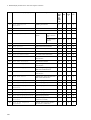
[Edition 7]
Summary of amendments
Item
Changes
Communication is not possible or is disconnected
• Items to be checked for the optional license OP-NPAR were
added.
No RIP routing information exists
• Items to be checked for the optional license OP-NPAR were
added.
No OSPF routing information exists
• Items to be checked for the optional license OP-NPAR were
added.
No BGP4 routing information exists
• Items to be checked for the optional license OP-NPAR were
added.
• The actions to be taken were changed.
No routing information exists in the VRF
• This subsection was added.
Communication failures in the IPv4 multicast routing
functionality
• Items for analyzing failures were added.
• Items to be checked for the optional license OP-NPAR were
added.
No BGP4+ routing information exists
• The actions to be taken were changed.
Communication failures in the IPv6 multicast routing
functionality
• Items for analyzing failures were added.
Communication failures occurring when Web
authentication is used
• Items for analyzing failures were added.
• The actions to be taken were changed.
Communication failures occurring when MAC-based
authentication is used
• The actions to be taken were changed.
Communication is not possible with the VRRP
configuration of IPv4 networks
• Items for analyzing failures of the grouping functionality were
added.
Communication is not possible with the VRRP
configuration of IPv6 networks
• Items for analyzing failures of the grouping functionality were
added.
Packet congestion in CPU processing does not recover
• This section was added.
Item
Detailed display contents of the "show tech-support"
command
Changes
• Content displayed by the added or changed commands was
added.
[Edition 6]
Summary of amendments
Item
Changes
Information cannot be entered from the console or
does not appear correctly
• The item "After line disconnection, reconnection is not
possible." for problems occurring during connection to a
modem was added.
Ethernet port cannot be connected
• Actions to be taken when L2 loop detection functionality
deactivates the port (makes it inactive) were added to the
port status check items.
Actions to be taken for 10BASE-T/100BASE-TX/
1000BASE-T problems
• Items to be checked for pin-mapping depending on the port
settings were added.
Failures occurring when the Spanning Tree
functionality is used
• Actions to be taken when the Spanning Tree functionality is
used with the Ring Protocol were added.
Multicast forwarding by IGMP snooping is not
possible
• Items to be checked when using IPv4 multicast concurrently
were added.
Multicast forwarding by MLD snooping is not
possible
• Items to be checked when using IPv6 multicast concurrently
were added.
Communication is not possible on the IPv4 PIM-SM
networks
• Actions to be taken when checking by using the show
igmp-snooping command
Communication is not possible on the IPv4 PIM-SSM
networks
• Actions to be taken when checking by using the show
igmp-snooping command
Communication is not possible on the IPv6 PIM-SM
networks
• Actions to be taken when checking by using the show
mld-snooping command
Communication is not possible on the IPv6 PIM-SSM
networks
• Actions to be taken when checking by using the show
mld-snooping command
Communication failures occurring when Web
authentication is used
• Actions to be taken when an operation log message is output,
and when authentication for a terminal subject to
authentication fails completely were added.
Transferring maintenance information files
• The procedure for transferring information when a
configuration file failure occurs was added.
Detailed display contents of the "show tech-support"
command
• Content displayed by the added commands was added.
[Edition 5]
Summary of amendments
Item
MAC-based authentication
Changes
• This item was added.
[Edition 4]
Summary of amendments
Item
Ring Protocol
Changes
• This item was added.
[Edition 3]
Summary of amendments
Item
Changes
Additional model
• A description relating to the additional model was added.
Web Authentication
• This item was added.
sFlow statistics
• This item was added.
IEEE 802.3ah/UDLD functionality
• This item was added.
[Edition 2]
Summary of amendments
Item
Changes
Additional model
• A description relating to the additional model was added.
Authentication VLAN
• This item was added.
SNMPv3
• This item was added.
Detailed display contents of the "show tech-support"
command
• This item was added.
Preface
Relevant products
This manual applies to the models in the AX6700S, AX6600S, AX6300S, AX3800S,
AX3600S, and AX2400S series of switches.
Before you operate the equipment, carefully read the manual and make sure that you understand
all instructions and cautionary notes. After reading the manual, keep it in a convenient place for
easy reference.
Corrections to the manual
Corrections to this manual are contained in the Manual Corrections.
Intended readers
This manual is intended for system administrators who configure and operate a network system
that uses AX6700S, AX6600S, AX6300S, AX3800S, AX3600S, and AX2400S series
switches.
Readers must have an understanding of the following:
• The basics of network system management
Manual URL
You can view this manual on our website at:
http://www.alaxala.com/en/
i
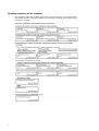
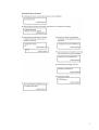
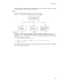
Reading sequence of the manuals
The following shows the manuals you need to consult according to your requirements
determined from the following workflow for installing, setting up, and starting regular
operation of a switch.
AX6700S, AX6600S, and AX6300S series switches
ii
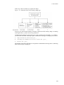
AX3800S and AX3650S series switches
iii
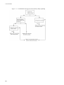
AX3640S and AX3630S series switches
iv
AX2400S series switches
v
Abbreviations used in the manual
AC
ACK
ADSL
ALG
ANSI
ARP
AS
AUX
BCU
BGP
BGP4
BGP4+
bit/s
BPDU
BRI
BSU
CC
CDP
CFM
CIDR
CIR
CIST
CLNP
CLNS
CONS
CRC
CSMA/CD
CSNP
CST
CSU
DA
DC
DCE
DHCP
DIS
DNS
DR
DSAP
DSCP
DTE
DVMRP
E-Mail
EAP
EAPOL
EFM
ES
FAN
FCS
FDB
FQDN
FTTH
GBIC
GSRP
HMAC
IANA
ICMP
ICMPv6
ID
IEC
IEEE
IETF
IGMP
IP
IPCP
IPv4
vi
Alternating Current
ACKnowledge
Asymmetric Digital Subscriber Line
Application Level Gateway
American National Standards Institute
Address Resolution Protocol
Autonomous System
Auxiliary
Basic Control Unit
Border Gateway Protocol
Border Gateway Protocol - version 4
Multiprotocol Extensions for Border Gateway Protocol - version 4
bits per second (can also appear as bps)
Bridge Protocol Data Unit
Basic Rate Interface
Basic Switching Unit
Continuity Check
Cisco Discovery Protocol
Connectivity Fault Management
Classless Inter-Domain Routing
Committed Information Rate
Common and Internal Spanning Tree
ConnectionLess Network Protocol
ConnectionLess Network System
Connection Oriented Network System
Cyclic Redundancy Check
Carrier Sense Multiple Access with Collision Detection
Complete Sequence Numbers PDU
Common Spanning Tree
Control and Switching Unit
Destination Address
Direct Current
Data Circuit terminating Equipment
Dynamic Host Configuration Protocol
Draft International Standard/Designated Intermediate System
Domain Name System
Designated Router
Destination Service Access Point
Differentiated Services Code Point
Data Terminal Equipment
Distance Vector Multicast Routing Protocol
Electronic Mail
Extensible Authentication Protocol
EAP Over LAN
Ethernet in the First Mile
End System
Fan Unit
Frame Check Sequence
Filtering DataBase
Fully Qualified Domain Name
Fiber To The Home
GigaBit Interface Converter
Gigabit Switch Redundancy Protocol
Keyed-Hashing for Message Authentication
Internet Assigned Numbers Authority
Internet Control Message Protocol
Internet Control Message Protocol version 6
Identifier
International Electrotechnical Commission
Institute of Electrical and Electronics Engineers, Inc.
the Internet Engineering Task Force
Internet Group Management Protocol
Internet Protocol
IP Control Protocol
Internet Protocol version 4
IPv6
IPV6CP
IPX
ISO
ISP
IST
L2LD
LAN
LCP
LED
LLC
LLDP
LLPQ
LLQ+3WFQ
LLRLQ
LSP
LSP
LSR
MA
MAC
MC
MD5
MDI
MDI-X
MEP
MIB
MIP
MRU
MSTI
MSTP
MSU
MTU
NAK
NAS
NAT
NCP
NDP
NET
NIF
NLA ID
NPDU
NSAP
NSSA
NTP
OADP
OAM
OSPF
OUI
packet/s
PAD
PAE
PC
PCI
PDU
PICS
PID
PIM
PIM-DM
PIM-SM
PIM-SSM
PoE
PRI
PS
PSNP
PSP
QoS
QSFP+
Internet Protocol version 6
IP Version 6 Control Protocol
Internetwork Packet Exchange
International Organization for Standardization
Internet Service Provider
Internal Spanning Tree
Layer 2 Loop Detection
Local Area Network
Link Control Protocol
Light Emitting Diode
Logical Link Control
Link Layer Discovery Protocol
Low Latency Priority Queueing
Low Latency Queueing + 3 Weighted Fair Queueing
Low Latency Rate Limited Queueing
Label Switched Path
Link State PDU
Label Switched Router
Maintenance Association
Media Access Control
Memory Card
Message Digest 5
Medium Dependent Interface
Medium Dependent Interface crossover
Maintenance association End Point
Management Information Base
Maintenance domain Intermediate Point
Maximum Receive Unit
Multiple Spanning Tree Instance
Multiple Spanning Tree Protocol
Management and Switching Unit
Maximum Transfer Unit
Not AcKnowledge
Network Access Server
Network Address Translation
Network Control Protocol
Neighbor Discovery Protocol
Network Entity Title
Network Interface
Next-Level Aggregation Identifier
Network Protocol Data Unit
Network Service Access Point
Not So Stubby Area
Network Time Protocol
Octpower Auto Discovery Protocol
Operations,Administration,and Maintenance
Open Shortest Path First
Organizationally Unique Identifier
packets per second (can also appear as pps)
PADding
Port Access Entity
Personal Computer
Protocol Control Information
Protocol Data Unit
Protocol Implementation Conformance Statement
Protocol IDentifier
Protocol Independent Multicast
Protocol Independent Multicast-Dense Mode
Protocol Independent Multicast-Sparse Mode
Protocol Independent Multicast-Source Specific Multicast
Power over Ethernet
Primary Rate Interface
Power Supply
Partial Sequence Numbers PDU
Packet Switching Processor
Quality of Service
Quad Small Form factor Pluggable Plus
vii
RA
RADIUS
RDI
REJ
RFC
RGQ
RIP
RIPng
RMON
RPF
RQ
RSTP
SA
SD
SDH
SDU
SEL
SFD
SFP
SFP+
SMTP
SNAP
SNMP
SNP
SNPA
SOP
SPF
SSAP
STP
TA
TACACS+
TCP/IP
TLA ID
TLV
TOS
TPID
TTL
UDLD
UDP
UPC
UPC-RED
uRPF
VAA
VLAN
VPN
VRF
VRRP
WAN
WDM
WFQ
WGQ
WRED
WS
WWW
XFP
Router Advertisement
Remote Authentication Dial In User Service
Remote Defect Indication
REJect
Request For Comments
Rate Guaranteed Queueing
Routing Information Protocol
Routing Information Protocol next generation
Remote Network Monitoring MIB
Reverse Path Forwarding
ReQuest
Rapid Spanning Tree Protocol
Source Address
Secure Digital
Synchronous Digital Hierarchy
Service Data Unit
NSAP SELector
Start Frame Delimiter
Small Form factor Pluggable
Enhanced Small Form factor Pluggable
Simple Mail Transfer Protocol
Sub-Network Access Protocol
Simple Network Management Protocol
Sequence Numbers PDU
Subnetwork Point of Attachment
System Operational Panel
Shortest Path First
Source Service Access Point
Spanning Tree Protocol
Terminal Adapter
Terminal Access Controller Access Control System Plus
Transmission Control Protocol/Internet Protocol
Top-Level Aggregation Identifier
Type, Length, and Value
Type Of Service
Tag Protocol Identifier
Time To Live
Uni-Directional Link Detection
User Datagram Protocol
Usage Parameter Control
Usage Parameter Control - Random Early Detection
unicast Reverse Path Forwarding
VLAN Access Agent
Virtual LAN
Virtual Private Network
Virtual Routing and Forwarding/Virtual Routing and Forwarding
Instance
Virtual Router Redundancy Protocol
Wide Area Network
Wavelength Division Multiplexing
Weighted Fair Queueing
Weighted Guaranteed Queueing
Weighted Random Early Detection
Work Station
World-Wide Web
10 gigabit small Form factor Pluggable
Conventions: The terms "Switch" and "switch"
The term Switch (upper-case "S") is an abbreviation for any or all of the following models:
AX6700S, AX6600S, and AX6300S series switches
AX3800S and AX3600S series switches
AX2400S series switch
The term switch (lower-case "s") might refer to a Switch, another type of switch from the
viii
current vendor, or a switch from another vendor. The context decides the meaning.
Conventions: KB, MB, GB, and TB
This manual uses the following conventions: 1 KB (kilobyte) is 1024 bytes, 1 MB (megabyte)
is 10242 bytes, 1 GB (gigabyte) is 10243 bytes, 1 TB (terabyte) is 10244 bytes.
ix
Contents
Preface
i
Safety Information [AX6700S]
xv
Safety Information [AX6600S]
xxvii
Safety Information [AX6300S]
xxxix
Safety Information [AX3800S] [AX3600S] [AX2400S]
li
1. Overview
1
1.1 Overview of analyzing failures ................................................................................................2
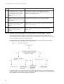
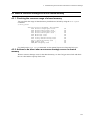
1.2 Overview of analyzing failures of all or part of the Switch ....................................................3
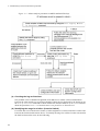
1.2.1 Failure analysis for AX6700S, AX6600S, and AX6300S series switches ..................3
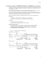
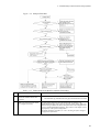
1.2.2 Failure analysis for AX3800S, AX3600S, and AX2400S series switches ..................5
1.3 Overview of analyzing failures of functionality ....................................................................10
2. Troubleshooting Switch Failures
15
2.1 Troubleshooting faults for AX6700S, AX6600S, and AX6300S series switches .................16
2.1.1 Procedure for handling switch faults ..........................................................................16
2.1.2 Replacing the switch and optional modules ...............................................................18
2.2 Troubleshooting faults for AX3800S, AX3600S, and AX2400S series switches .................19
2.2.1 Procedure for handling switch faults ..........................................................................19
2.2.2 Isolating the cause of external redundant power unit failures ....................................20
2.2.3 Replacing the switch and optional modules ...............................................................21
3. Troubleshooting Functional Failures During Operation
23
3.1 Problems related to login passwords .....................................................................................24
3.1.1 Forgotten login user password ...................................................................................24
3.1.2 Forgotten password for administrator mode ..............................................................24
3.2 Memory card problems ..........................................................................................................25
3.2.1 The "show system" or "show mc" command displays "MC : --------" .......................25
3.2.2 "MC not found." is displayed when the memory card is accessed .............................25
3.3 Operation terminal problems .................................................................................................26
3.3.1 Information cannot be entered from the console or does not appear correctly ..........26
3.3.2 Login from a remote terminal is not possible ............................................................27
3.3.3 Returning to administrator mode from configuration command mode is not possible ................................................................................................................................28
3.3.4 Login authentication using RADIUS/TACACS+ is not possible ..............................29
3.3.5 Command authorization using RADIUS/TACACS+ and local is not possible .........30
3.4 Stack configuration problems ................................................................................................31
3.4.1 Stack configuration is not possible .............................................................................31
3.4.2 Stack configuration cannot be edited .........................................................................32
3.4.3 Configuring a stack with a specific member switch as the master switch .................32
3.5 Network interface communication failures ...........................................................................33
3.5.1 Ethernet port cannot be connected .............................................................................33
3.5.2 BSU/PSP communication failures .............................................................................35
3.5.3 Actions to be taken for 10BASE-T/100BASE-TX/1000BASE-T problems .............36
3.5.4 Actions to be taken for 100BASE-FX/1000BASE-X problems ................................38
3.5.5 Actions to be taken for 10GBASE-R/40GBASE-R problems ...................................41
xi
3.5.6 Actions to be taken for PoE problems ....................................................................... 43
3.5.7 Communication failures when link aggregation is used ............................................ 44
3.6 Layer 2 network communication failures ............................................................................. 46
3.6.1 Layer 2 communication by VLANs is not possible ................................................... 46
3.6.2 Failures occurring when the Spanning Tree functionality is used ............................. 49
3.6.3 Failures occurring when the Ring Protocol functionality is used .............................. 50
3.6.4 Multicast forwarding by IGMP snooping is not possible .......................................... 52
3.6.5 Multicast forwarding by MLD snooping is not possible ........................................... 55
3.7 IPv4 network communication failures .................................................................................. 59
3.7.1 Communication is not possible or is disconnected .................................................... 59
3.7.2 IP addresses cannot be assigned by the DHCP functionality .................................... 63
3.7.3 Dynamic DNS link does not work in the DHCP functionality .................................. 69
3.8 IPv4 unicast routing communication failures ....................................................................... 72
3.8.1 No RIP routing information exists ............................................................................. 72
3.8.2 No OSPF routing information exists ......................................................................... 72
3.8.3 No BGP4 routing information exists ......................................................................... 73
3.8.4 IPv4 routing information cannot be found in VRF .................................................... 74
3.9 Communication failures in the IPv4 multicast routing functionality .................................... 75
3.9.1 Communication is not possible on the IPv4 PIM-SM networks ............................... 75
3.9.2 Multicast data is forwarded twice in the IPv4 PIM-SM network .............................. 79
3.9.3 Communication is not possible on the IPv4 PIM-SSM networks ............................. 79
3.9.4 Multicast data is forwarded twice in the IPv4 PIM-SSM network ............................ 82
3.9.5 IPv4 multicast communication problems in VRF ..................................................... 83
3.9.6 Problems that occur during IPv4 multicast communication in the extranet .............. 84
3.9.7 Communication is not possible on the IPv4 PIM-DM networks ............................... 84
3.9.8 Multicast data is forwarded twice in the IPv4 PIM-DM network ............................. 87
3.10 IPv6 network communication failures ................................................................................ 88
3.10.1 Communication is not possible or is disconnected .................................................. 88
3.10.2 IPv6 DHCP relay communication problems ........................................................... 91
3.10.3 Troubleshooting IPv6 DHCP server problems ........................................................ 94
3.11 IPv6 unicast routing communication failures ..................................................................... 99
3.11.1 RIPng routing information cannot be found ............................................................ 99
3.11.2 OSPFv3 routing information cannot be found ......................................................... 99
3.11.3 No BGP4+ routing information exists ................................................................... 100
3.11.4 No IPv6 routing information exists in the VRF ..................................................... 101
3.12 Communication failures in the IPv6 multicast routing functionality ................................ 102
3.12.1 Communication is not possible on the IPv6 PIM-SM networks ........................... 102
3.12.2 Multicast data is forwarded twice in the IPv6 PIM-SM network .......................... 106
3.12.3 Communication is not possible on the IPv6 PIM-SSM networks ......................... 106
3.12.4 Multicast data is forwarded twice in the IPv6 PIM-SSM network ........................ 109
3.12.5 IPv6 multicast communication problems in VRF ................................................. 110
3.12.6 IPv6 multicast communication problems in an extranet ........................................ 110
3.13 Layer 2 authentication communication failures ................................................................ 112
3.13.1 Communication failures occurring when IEEE 802.1X is used ............................ 112
3.13.2 Communication failures occurring when Web authentication is used ................... 115
3.13.3 Communication failures occurring when MAC-based authentication is used ...... 120
3.13.4 Communication failures occurring when an authentication VLAN is used .......... 123
3.14 Communication failures in the high-reliability functionality ........................................... 127
3.14.1 GSRP communication failures .............................................................................. 127
3.14.2 Communication is not possible with the VRRP configuration of IPv4 networks . 129
3.14.3 Communication is not possible with the VRRP configuration of IPv6 networks . 131
3.14.4 Communication is not possible with uplink redundancy ....................................... 134
3.15 SNMP communication failures ......................................................................................... 136
3.15.1 MIBs cannot be obtained from the SNMP manager .............................................. 136
3.15.2 Traps cannot be received by the SNMP manager .................................................. 136
3.16 Troubleshooting the sFlow statistics (flow statistics) functionality .................................. 138
xii
3.17
3.18
3.19
3.20
3.21
3.22
3.23
3.24
3.25
3.26
3.27
3.28
3.29
3.16.1 sFlow packets cannot be sent to the collector ........................................................138
3.16.2 Flow samples cannot be sent to the collector .........................................................140
3.16.3 Counter samples cannot be sent to the collector ....................................................141
Communication failures in the neighboring device management functionality ................142
3.17.1 Neighboring device information cannot be obtained by the LLDP functionality ..142
3.17.2 Neighboring device information cannot be obtained by the OADP functionality .142
NTP communication failures .............................................................................................144
3.18.1 The Switch cannot be synchronized by using NTP ................................................144
Communication failures in the IEEE 802.3ah/UDLD functionality .................................145
3.19.1 Port is in inactivate status by the IEEE 802.3ah/UDLD functionality ...................145
Problems due to the redundant configuration of the BCU, CSU, or MSU .......................146
3.20.1 Active-standby switchover is not possible .............................................................146
Problems due to the redundant configuration of the BSU .................................................147
3.21.1 BSU switchover is not possible ..............................................................................147
Problems due to the redundant configuration of the NIF ..................................................149
3.22.1 The standby NIF cannot be switched to the active system ....................................149
3.22.2 The active NIF cannot be switched to the standby system ....................................149
Power saving-related problems .........................................................................................150
3.23.1 Scheduling is disabled ............................................................................................150
Packet congestion in CPU processing does not recover ....................................................151
Communication failures in filters and QoS configurations ...............................................153
3.25.1 Checking the filters and QoS configuration information .......................................153
Access list logging problems .............................................................................................155
3.26.1 Actions to be taken when access list logs are not output .......................................155
DHCP snooping problems .................................................................................................156
3.27.1 Problems related to DHCP .....................................................................................156
3.27.2 Problems related to saving the binding database ...................................................157
3.27.3 Problems related to ARP ........................................................................................158
3.27.4 Communication problems due to causes other than DHCP and ARP ....................158
Policy-based routing problems ..........................................................................................160
3.28.1 Actions to take when packets are not forwarded in policy-based routing .............160
3.28.2 Actions to be taken when the tracking functionality of policy-based routing is in an
unexpected track state ..............................................................................................162
Policy-based switching problems ......................................................................................165
3.29.1 Actions to be taken when packets are not forwarded in policy-based switching ...165
4. Troubleshooting Communication Failures Due to a Resource Shortage
167
4.1 MAC address table resource shortage .................................................................................168
4.1.1 Checking the MAC address table resource usage ....................................................168
4.1.2 Actions to be taken when a MAC address table resource shortage occurs ..............168
4.2 When a VLAN identification table resource shortage occurs .............................................171
4.2.1 Checking the VLAN identification table resource usage .........................................171
4.2.2 Actions to be taken when a VLAN identification table resource shortage occurs ...171
4.3 When a resource shortage occurs in shared memory ..........................................................173
4.3.1 Checking the resource usage of shared memory ......................................................173
4.3.2 Actions to be taken when a resource shortage occurs in shared memory ................173
5. Obtaining Failure Information
175
5.1 Collecting maintenance information ...................................................................................176
5.1.1 Maintenance information .........................................................................................176
5.1.2 Collecting failure information by using the "dump" command ...............................178
5.2 Transferring maintenance information files ........................................................................183
5.2.1 Transferring files using the "ftp" command .............................................................183
5.2.2 Transferring files using the "zmodem" command ....................................................185
5.3 Collecting information and transferring files by using the "show tech-support" command ........................................................................................................................................187
xiii
5.4 Collecting information and transferring files by using the "ftp" command on a remote terminal
....................................................................................................................................... 190
5.5 Writing data to a memory card ............................................................................................ 193
5.5.1 Writing data to a memory card by using an operation terminal .............................. 193
6. Line Testing
195
6.1 Testing a line ....................................................................................................................... 196
6.1.1 Internal loopback test ............................................................................................... 196
6.1.2 Loop connector loopback test .................................................................................. 197
6.1.3 Loop connectors specification ................................................................................. 197
7. Device Restart
199
7.1 Restarting the device ........................................................................................................... 200
7.1.1 Device restart ........................................................................................................... 200
Appendix
205
A Detailed Display Contents of the "show tech-support" Command ....................................... 206
A.1 Detailed display contents of the "show tech-support" command .............................. 206
Index
xiv
233
Safety Information [AX6700S]
Using AX6700S series switches correctly and safely
• This guide provides important information for ensuring safe use of AX6700S series
switches. Please read this guide completely before using the Switch.
• Keep this guide handy after finishing it, so that it is available for later reference.
• Operate the Switch according to the instructions and procedures provided in this guide.
• Heed all warnings and cautions on the Switch in this guide. Failure to do so could result in
injury or damage to the Switch.
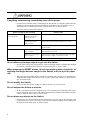
Caution indications
These indications are intended to ensure safe and correct use of the Switch and to prevent
serious injury, and equipment and property damage. Make sure you fully understand the
meaning of the indications before continuing with the main body of this manual.
Ignoring instructions preceded by this indication and using the Switch incorrectly could result in death or serious injury
to yourself and others.
Ignoring instructions preceded by this indication and using the Switch incorrectly could result in injury to yourself and
others.
Ignoring instructions preceded by this indication and using the Switch incorrectly could result in serious damage to the
Switch or nearby property.
Information preceded by this indication is supplementary information that, if ignored, will not result in physical injury
or serious damage to the Switch.
Unauthorized operations
Do not attempt to perform any operations that are not described in this guide.
In the event of a Switch problem, perform one of the following operations, and then contact
maintenance personnel.
• If the Switch has an AC power supply unit, turn off the Switch, and then unplug the power
cable.
• If the Switch has a DC power supply unit, turn off the Switch, and then set the power
supply circuit breaker to OFF.
Using common sense
The warnings and cautions provided on the Switch and in this guide have been selected after
careful consideration.
Nevertheless, there is always the possibility of the unexpected occurring. Therefore, while
using a Switch, stay alert and use common sense in addition to following all instructions.
xv
If anything seems wrong, immediately turn off the power.
• If smoke or an unusual smell is emanating from the Switch, or if liquid is spilled into the
Switch or a foreign object falls into the Switch, immediately turn off Switch power as
described below. Continuing operation could result in fire or electric shock.
• If the Switch has an AC power supply unit, turn off the Switch, and then unplug the power
cable.
• If the Switch has a DC power supply unit, turn off the Switch, and then set the power
supply circuit breaker to OFF. This is required for terminal connections.
Do not place the Switch in an unstable location.
• When installing the Switch on a table, position the Switch horizontally on a worktable
strong enough to bear the weight of the Switch. Placing the Switch in an unstable location,
such as on an unsteady or tilting surface, might cause the Switch to fall, resulting in serious
injury to yourself and others.
Do not remove the Switch cover.
• Do not remove the Switch cover. Doing so could result in electric shock.
Do not allow any foreign objects to get into the Switch.
• Do not insert or drop any foreign objects, such as anything metallic or flammable, through
the Switch's ventilation slots. Doing so could result in fire or electric shock.
Do not modify the Switch.
• Do not modify the Switch. Doing so could result in fire or electric shock.
Do not subject the Switch to shocks.
• In the event that the Switch is dropped or any of its components are damaged, turn off the
power, unplug the power cable, and contact maintenance personnel. Discontinue using the
cable to avoid the risk of fire or electric shock.
Do not place any objects on the Switch.
• Do not place any metallic object such as a small pin or a paper clip or any container with
a liquid, such as a vase or a flowerpot, on the Switch. Liquid or metallic objects falling into
the Switch could result in fire or electric shock.
Use the Switch only with the indicated power supply.
• Do not use the Switch at any voltage other than the indicated voltage. Doing so could result
in fire or electric shock.
Ensure that the capacity for incoming current to the distribution board is
greater than the operating current of the circuit breaker.
• Ensure that the capacity for incoming current to the distribution board is greater than the
operating current of the circuit breaker. If it is not, the circuit breaker might not operate
properly in the event of a failure, which could result in a fire.
Ground the Switch.
• Up to 3.5 mA of leakage current flows through this Switch. When connecting the Switch
to an AC power supply, always use a grounded power outlet for the switch. Using the
xvi
switch without grounding could result in electric shock or failures due to electrical noise.
• When the Switch is connected to a DC power supply unit, always connect the ground
terminal for proper grounding. Using the switch without grounding could result in electric
shock or failures due to electrical noise.
Systemize the power supply into 2 systems
• When setting up redundant power by connecting the Switch to a power supply greater than
AC230V, systemize the power supply into 2 systems so power can be supplied from each
system.
• When the power supplied from one system causes a maximum of 5 mA of leakage current
per device.
Connecting and disconnecting a DC power cable must be performed by a
trained technician or maintenance personnel.
• Connecting and disconnecting a DC power cable must be performed by a trained
technician or maintenance personnel. Terminal connections are required for connection of
the DC power cable to the power facility. For this reason, incorrect handling of the DC
power cable could result in fire or electric shock.
Set the power supply circuit breaker to OFF before connecting or
disconnecting the DC power cable.
• Set the power supply circuit breaker to OFF before connecting or disconnecting the DC
power cable. Connecting or disconnecting the cable with the circuit breaker set to ON
could result in an electric shock.
Place an insulation cover over the 0 V and -48 V terminals of DC power
cables.
• When using a DC power cable, place an insulation cover over the 0 V and -48 V terminals.
Using the terminals without an insulation cover could result in electric shock.
When using a DC power supply unit, do not use the terminal board with its
cover removed.
• When using a DC power supply unit, place a cover over the terminal board after
connecting the DC power cable. Using the terminal board without a cover could result in
electric shock.
Do not touch the voltage-measuring terminals.
• A power supply unit has voltage-measuring terminals. Do not use the terminals because
they are used for a factory inspection before shipment. In addition, do not insert anything
with a sharp point, such as a pin or paper clip, into the voltage-measuring terminals. Doing
so could result in fire or electric shock.
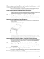
Installing and carrying the switch must be performed by trained personnel
or a professional carrier.
• The maximum weight of the switch is 82 kg. Installing and carrying the switch must be
performed by trained personnel or a professional carrier. If anyone other than those
mentioned above performs these tasks, the switch might fall, resulting in serious injury.
Use a handling device such as a hand lifter when installing or carrying the switch. Carrying
the switch without using a handling device might cause the switch to fall, resulting in
serious injury. Note that the following label is attached to the Switch.
xvii
Handle power cables carefully.
• Do not place anything heavy on a power cable. Do not pull, bend, or process a cable. Doing
so could damage the cable, resulting in fire or electric shock. If the power cable is covered
by a carpet, it is easy to forget that the cable is there and to place something heavy on it.
• Use the supplied or a designated power cable. Using another cable could result in fire or
electric shock. In addition, do not use the supplied cable with other devices. Doing so could
result in a fire or electric shock.
• If the power cable is damaged so that the wires underneath the covering are visible or cut,
stop using it, and ask maintenance personnel to replace it. Discontinue using the cable to
avoid the risk of fire or electric shock.
• Make sure the power plug is free of dust, and insert the plug completely up to the base of
the prongs to prevent any looseness. Using a power plug with dust on it or one that is
imperfectly connected could result in fire or electric shock.
Do not overload the power outlet.
• Do not overload the power outlet by connecting multiple power plugs to the same outlet.
Overloading the outlet could result in fire or the circuit breaker tripping due to excessive
power used. This might affect other equipment.
To turn off the power, turn off all power switches of the Switch or the
breaker.
• The Switch has multiple input power supplies. To turn off the power, turn off all power
switches of the Switch (if the Switch has an AC power supply unit) or the breaker (if the
Switch has a DC power supply unit). Note that the following label is attached to the
Switch.
Adding or replacing a module must be performed by a trained technician
or maintenance personnel.
• Adding or replacing optional modules must be performed by a trained technician or
maintenance personnel. Adding or replacing a power supply unit involves connecting and
disconnecting the power cable. If anyone other than those mentioned above performs these
tasks incorrectly, a fire, electric shock, or failure could result. In addition, using optional
modules incorrectly could result in injury or Switch malfunction.
xviii
When pressing the button of the basic control unit, do not use anything
with a fragile tip, or anything that might become caught in the switch, such
as a pin or paper clip.
• When pressing the button on the front panel of the basic control unit, do not use anything
with a fragile tip, or anything that might become caught in the switch, such as a pin or
paper clip. Doing so could result in fire or electric shock.
Disconnect the power cable before adding or replacing a power supply
unit.
• When adding or replacing a power supply unit, disconnect the power cable from the power
supply unit to be replaced. If the power cable is connected and the power switch is turned
off, power is still supplied to some circuits. Because of this, if you add or replace a power
supply unit with the power cable connected, a fire or electric shock could result.
Do not use an air duster near a flame.
• When cleaning the optical connectors, do not use an air duster that contains flammable gas
near a flame. Doing so could result in a fire.
xix
Do not install the Switch in a dusty or humid location.
• Do not install the Switch in a dusty or humid location. Doing so could result in fire or
electric shock.
• Condensation might form on the surfaces and the inside of the Switch if it is moved from
a cold location to a warm location. Using the Switch in this condition could result in fire
or electric shock. After moving the Switch between two locations with a large temperature
variation, let the Switch stand a few hours before using it.
Do not stack Switches on top of one another.
• Do not stack Switches on top of one another. Doing so might damage the Switch.
Furthermore, the Switch might fall, or become unbalanced, resulting in injury.
Do not step on the Switch, lean against it, or place anything on it.
• Do not step on the Switch, lean against it, or place anything on it. Doing so might damage
the Switch. Furthermore, the Switch might fall, or become unbalanced, resulting in injury.
When mounting the switch in a rack, use guide rails or a shelf.
• Rack mounting brackets of the Switch are for securing the Switch to the rack, not for
supporting the weight of the Switch. Use guide rails or a shelf. Note that you need to use
the guide rails or shelves that are supplied with the rack and that can support the weight of
the switch (when all optional modules are mounted).
Do not obstruct the ventilation slots.
• Do not obstruct the ventilation slots of the Switch. Doing so causes heat to accumulate
inside the Switch, and could result in a fire. Maintain a space of at least 70 mm around the
ventilation slots.
Do not allow hair or objects near the ventilation slots.
• Cooling fan units are mounted in the Switch. Do not allow anything near the ventilation
slots. Doing so causes heat to accumulate inside the Switch and could cause a failure. Do
not allow hair or other objects near the ventilation slots. They might be sucked into the
Switch, resulting in injury.
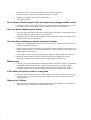
When moving the Switch, do not hold the handle of an optional module.
• When moving the Switch, do not hold the handle of a fan unit or power supply unit. The
handle might come off, resulting in the device falling and possibly causing injury.
Moreover, the fan unit or power supply unit might become damaged, resulting in a fire or
electric shock.
When moving a Switch, unplug all cables.
• Before moving a Switch, you must turn it off and unplug all cables. Failure to do so might
cause the Switch or cable to become deformed, or might damage the Switch, resulting in
fire or electric shock.
Do not drop optional modules.
• Handle the optional modules with care to avoid dropping them. Dropping them might
cause injury.
• A DC power supply unit weighs 5.6 kg and is 163 mm long. When removing a power
xx
supply unit from a Switch, hold the power supply unit tightly. Pulling a power supply unit
carelessly from a Switch might cause the power supply unit to fall, resulting in injury. The
following label is attached to a DC power supply unit.
Do not touch the inside of the Switch with your hands.
• Do not carelessly put your hands inside the Switch. The frame and components might
cause injury.
Be careful of heat when removing a basic control unit or network interface
unit.
• Some components installed on a basic control unit or network interface unit might be hot.
Do not touch the installed components. Doing so could result in burns.
When removing a fan unit, do not put your hands near the rotating fan.
• The fan might be rotating just after it is removed. Do not put hands or fingers near the fan
while it is rotating. Doing so could result in injury. The following label is attached to a fan
unit.
Handle the power cable carefully.
• Do not place the power cable near a heat-generating apparatus. The heat could melt the
cable coating, resulting in fire or electric shock.
• When connecting or disconnecting the power cable from the outlet, always hold the plug,
not the cable itself. Pulling the cable itself might cause the wires to break.
Do not touch the Switch directly if you have a metal allergy.
• The Switch is coated with zinc, nickel, gold, and other elements. Do not touch the Switch
directly if you have an allergic reaction to these metallic elements. Doing so might cause
eczema or skin irritation.
Avoid looking directly at laser beams.
• Network interface units with the following label attached use laser beams. Never look
directly into the optical transceiver.
xxi
Do not touch the SFP-T during operation and just after operation stops.
• During operation (when a link is established), the temperature of the SFP-T can rise to
65?C. Do not touch the device while it is operating or just after it stops. Doing so could
result in burns.
• When you remove the SFP-T, use the following procedure. Failure to do so could result in
burns.
1.
To remove the device when the Switch is turned on, execute the inactivate command,
and then wait five minutes before removing the device.
2.
To remove the device after turning off the Switch, turn off the Switch, wait five minutes,
and then remove the device.
• The following label is attached to the SFP-T.
Lithium battery
• The Switch has a lithium battery for the real-time clock. Incorrect handling of the lithium
battery could cause the battery to heat up, explode, or catch fire, resulting in injury or a
fire. Do not remove the battery from the Switch, disassemble it, heat it to 100C or higher,
incinerate it, or immerse it in water.
Cleaning
• Remove dust on and around the Switch regularly. In addition to causing the Switch to stop,
accumulated dust could result in a fire or electric shock.
xxii
Do not turn off the power during a software update (while the ppupdate
command is executing).
• The Switch automatically restarts after the ppupdate command is executed. Do not turn
off the power while the switch is restarting (wait until the STATUS LED of the basic
control unit changes from blinking green to solid green). Turning off the power could
result in a switch fault.
Handle memory cards carefully.
• When inserting a memory card, do not push the card too strongly or flick it with your
finger. When removing a memory card, do not forcibly pull out the card if it is locked.
Doing so might damage the connector of the memory card slot.
• When moving the Switch, remove memory cards. If a memory card is subjected to
excessive force when the Switch is moved, the connector of the memory card slot might
be damaged.
When the ACC LED is lit, do not remove the memory card or turn off the
power.
• When the ACC LED on the basic control unit is lit, the memory card is being accessed.
When a memory card is being accessed, do not remove the memory card or turn off the
power. Doing so might damage the memory card. In addition, some commands require a
certain amount of time after being entered to finish accessing the card. Make sure that the
memory card is no longer being accessed before removing the card or turning off the
power.
Do not attach any labels to a transceiver.
• A label attached to the transceiver indicates that the transceiver is a standard product from
ALAXALA or another manufacturer. However, such labels are attached where they do not
interfere with heat dissipation from the transceiver or the mechanism that prevents the
transceiver from coming loose from the cage. Attaching a label to a location that interferes
with these functions could cause a malfunction in the transceiver or damage to the network
interface units.
Ensure that voltage drop does not occur in the power facility due to inrush
current.
• Turning on the Switch causes inrush current. Ensure that voltage drop does not occur in
the power facility due to the inrush current. Voltage drop could affect not only the Switch,
but also other devices connected to the same power facility.
Turn off the power before connecting or disconnecting a power cable.
• Before connecting or disconnecting a power cable, turn off the power of the power supply
unit of the cable that is to be connected or disconnected.
When replacing a fan unit with the Switch turned on, observe the time limit.
• When replacing a fan unit with the Switch turned on, you must remove and replace the unit
within one minute. If this time limit is exceeded, the temperature inside the Switch rises.
This might affect other units.
xxiii
When carrying or packing a Switch and its optional modules, wear a wrist
strap to protect against static electricity.
• Be sure to wear an antistatic wrist strap. If you handle the Switch without wearing an
antistatic wrist strap, the Switch might be damaged by static electricity.
When removing optional modules, attach blank panels.
• When removing optional modules, attach blank panels. If you use the Switch without
attaching a blank panel, airflow through the Switch cannot be maintained. If airflow is not
maintained, the temperature inside the Switch rises, resulting in a failure.
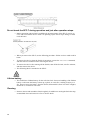
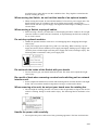
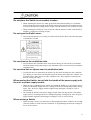
Be careful when installing an optional module.
• When installing an optional module, follow the procedures below. Not doing so could
result in a failure.
1.
Open the levers as shown in the figure.
2.
Hold the levers, and push the optional module slowly until the levers touch the Switch.
3.
Insert the optional module all the way by using the levers. When moving the levers, move
them slowly (by taking at least one second) without using excessive force.
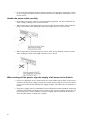
Before removing an optional module, loosen the screws completely.
• The levers are used to remove a basic control unit, basic switching unit, or network
interface unit. If the screws are not loosened completely, the optional module might be
damaged when the levers are opened.
When carrying and packing optional modules, handle them carefully.
• Do not touch the installed components and the solder surface when carrying or packing an
optional module, such as a basic control unit, basic switching unit, network interface unit,
memory card, transceiver, or power supply unit. Also, when storing an optional module,
use an antistatic bag.
Do not place a Switch in a high-temperature location.
• Do not place a Switch in direct sunlight or near a heater or other heat-generating apparatus.
Do not use a TV or a radio near a Switch.
• Do not use a TV or a radio near a Switch. Placing a Switch near a TV or a radio could affect
both devices. If you hear noise on the TV or radio, do the following:
xxiv
1.
Place the Switch as far away as possible from the TV or radio.
2.
Adjust the orientation of the TV or radio antenna.
3.
Use separate outlets.
Do not place a Switch where it will be exposed to hydrogen sulfide or salt.
• Placing a Switch in an area where sulfides are present, such as a hot-springs area, or in an
area with salty air, such as along a coast, could shorten the life of the Switch.
Use care when handling an air duster.
• Use an air duster specially designed for cleaning optical connectors. Using another type of
air duster could cause the ferrule tip to become dirty.
• Keep the nozzle or container of the air duster from coming into contact with the ferrule tip.
Contact could result in a malfunction.
Use care when handling an optical connector cleaner.
• Always use a dedicated optical connector cleaner. If you use another type of cleaner, the
ferrule tip might become dirty.
• Before cleaning, make sure that the tip of the optical connector cleaner is clean and free of
defects, such as lint, dirt, or other foreign substances. Using a cleaner with a defective tip
might damage the ferrule tip.
• Do not apply excessive pressure when cleaning. Doing so might damage the ferrule tip.
• Rotate the optical connector cleaner (stick) clockwise only. Rotating the cleaner
alternately clockwise and counterclockwise might damage the ferrule tip.
Maintenance
• Clean any dirty areas on the exterior of the Switch with a clean, dry cloth, or a cloth damp
with (but not soaked with) water or a neutral detergent. Do not use volatile organic
solutions (such as benzene or paint thinner), chemicals, chemically treated cloths, or
pesticides because these substances might deform, discolor, or damage the switch.
If the Switch will not be used for a long time
• For safety reasons, unplug the power cable from the outlet if the Switch will not be used
for a long time. If you are using a DC power supply unit, turn off the circuit breaker at the
supply of power.
Disposal of a Switch
• When disposing of a Switch, you should either follow local ordinances or regulations, or
contact your local waste disposal and treatment facility.
xxv
xxvi
Safety Information [AX6600S]
Using AX6600S series switches correctly and safely
• This guide provides important information for ensuring safe use of AX6600S series
switches. Please read this guide completely before using the Switch.
• Keep this guide handy after finishing it, so that it is available for later reference.
• Operate the Switch according to the instructions and procedures provided in this guide.
• Heed all warnings and cautions on the Switch in this guide. Failure to do so could result in
injury or damage to the Switch.
Caution indications
These indications are intended to ensure safe and correct use of the Switch and to prevent
serious injury, and equipment and property damage. Make sure you fully understand the
meaning of the indications before continuing with the main body of this manual.
Ignoring instructions preceded by this indication and using the Switch incorrectly could result in death or serious injury
to yourself and others.
Ignoring instructions preceded by this indication and using the Switch incorrectly could result in injury to yourself and
others.
Ignoring instructions preceded by this indication and using the Switch incorrectly could result in serious damage to the
Switch or nearby property.
Information preceded by this indication is supplementary information that, if ignored, will not result in physical injury
or serious damage to the Switch.
Unauthorized operations
Do not attempt to perform any operations that are not described in this guide.
In the event of a Switch problem, perform one of the following operations, and then contact
maintenance personnel.
• If the Switch has an AC power supply unit, turn off the Switch, and then unplug the power
cable.
• If the Switch has a DC power supply unit, turn off the Switch, and then set the power
supply circuit breaker to OFF.
Using common sense
The warnings and cautions provided on the Switch and in this guide have been selected after
careful consideration.
Nevertheless, there is always the possibility of the unexpected occurring. Therefore, while
using a Switch, stay alert and use common sense in addition to following all instructions.
xxvii
If anything seems wrong, immediately turn off the power.
• If smoke or an unusual smell is emanating from the Switch, or if liquid is spilled into the
Switch or a foreign object falls into the Switch, immediately turn off Switch power as
described below. Continuing operation could result in fire or electric shock.
• If the Switch has an AC power supply unit, turn off the Switch, and then unplug the power
cable.
• If the Switch has a DC power supply unit, turn off the Switch, and then set the power
supply circuit breaker to OFF. This is required for terminal connections.
Do not place the Switch in an unstable location.
• When installing the Switch on a table, position the Switch horizontally on a worktable
strong enough to bear the weight of the Switch. Placing the Switch in an unstable location,
such as on an unsteady or tilting surface, might cause the Switch to fall, resulting in serious
injury to yourself and others.
Do not remove the Switch cover.
• Do not remove the Switch cover. Doing so could result in electric shock.
Do not allow any foreign objects to get into the Switch.
• Do not insert or drop any foreign objects, such as anything metallic or flammable, through
the Switch's ventilation slots. Doing so could result in fire or electric shock.
Do not modify the Switch.
• Do not modify the Switch. Doing so could result in fire or electric shock.
Do not subject the Switch to shocks.
• In the event that the Switch is dropped or any of its components are damaged, turn off the
power, unplug the power cable, and contact maintenance personnel. Discontinue using the
cable to avoid the risk of fire or electric shock.
Do not place any objects on the Switch.
• Do not place any metallic object such as a small pin or a paper clip or any container with
a liquid, such as a vase or a flowerpot, on the Switch. Liquid or metallic objects falling into
the Switch could result in fire or electric shock.
Use the Switch only with the indicated power supply.
• Do not use the Switch at any voltage other than the indicated voltage. Doing so could result
in fire or electric shock.
Ensure that the capacity for incoming current to the distribution board is
greater than the operating current of the circuit breaker.
• Ensure that the capacity for incoming current to the distribution board is greater than the
operating current of the circuit breaker. If it is not, the circuit breaker might not operate
properly in the event of a failure, which could result in a fire.
Ground the Switch.
• Each Switch has at most 3.5 mA of leakage current. When the Switch is connected to an
AC power supply unit, always use a grounded power outlet. Using the Switch without
xxviii
grounding could result in electric shock or failures due to electrical noise.
• When the Switch is connected to a DC power supply unit, always connect the ground
terminal for proper grounding. Using the Switch without grounding could result in electric
shock or failures due to electrical noise.
Connecting and disconnecting a DC power cable must be performed by a
trained technician or maintenance personnel.
• Connecting and disconnecting a DC power cable must be performed by a trained
technician or maintenance personnel. Terminal connections are required for connection of
the DC power cable to the power facility. For this reason, incorrect handling of the DC
power cable could result in fire or electric shock.
Set the power supply circuit breaker to OFF before connecting or
disconnecting the DC power cable.
• Set the power supply circuit breaker to OFF before connecting or disconnecting the DC
power cable. Connecting or disconnecting the cable with the circuit breaker set to ON
could result in an electric shock.
Place an insulation cover over the 0 V and -48 V terminals of DC power
cables.
• When using a DC power cable, place an insulation cover over the 0 V and -48 V terminals.
Using the terminals without an insulation cover could result in electric shock.
When using a DC power supply unit, do not use the terminal board with its
cover removed.
• When using a DC power supply unit, place a cover over the terminal board after
connecting the DC power cable. Using the terminal board without a cover could result in
electric shock.
Do not touch the voltage-measuring terminals.
• A power supply unit has voltage-measuring terminals. This terminal is used for a factory
inspection before shipment. Because of this, do not use this terminal. In addition, do not
insert anything with a sharp point, such as a pin or paper clip, into the voltage-measuring
terminals. Doing so could result in fire or electric shock.
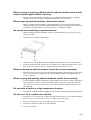
Installing and carrying a Switch must be performed by at least three
people.
• The weight of the Switches is as shown in the table below. Installing and carrying a Switch
must be performed by at least three people. If these tasks are performed by fewer than three
people, the Switch might fall, resulting in serious injury.
Number of people required to carry a Switch
Model
Weight
AX6604S
45 kg
AX6608S
64 kg
Number of people required
Three or more people
Note that the following label is attached to the Switch.
xxix
Handle power cables carefully.
• Do not place anything heavy on a power cable. Do not pull, bend, or process a cable. Doing
so could damage the cable, resulting in fire or electric shock. If the power cable is covered
by a carpet, it is easy to forget that the cable is there and to place something heavy on it.
• Use the supplied or a designated power cable. Using another cable could result in fire or
electric shock. In addition, do not use the supplied cable with other devices. Doing so could
result in a fire or electric shock.
• If the power cable is damaged so that the wires underneath the covering are visible or cut,
stop using it, and ask maintenance personnel to replace it. Discontinue using the cable to
avoid the risk of fire or electric shock.
• Make sure the power plug is free of dust, and insert the plug completely up to the base of
the prongs to prevent any looseness. Using a power plug with dust on it or one that is
imperfectly connected could result in fire or electric shock.
Do not overload the power outlet.
• Do not overload the power outlet by connecting multiple power plugs to the same outlet.
Overloading the outlet could result in fire or the circuit breaker tripping due to excessive
power used. This might affect other equipment.
To turn off the power, turn off all power switches of the Switch or the
breaker.
• The Switch has multiple input power supplies. To turn off the power, turn off all power
switches of the Switch (if the Switch has an AC power supply unit) or the breaker (if the
Switch has a DC power supply unit). Note that the following label is attached to the
Switch.
Adding or replacing a module must be performed by a trained technician
or maintenance personnel.
• Adding or replacing optional modules must be performed by a trained technician or
maintenance personnel. Adding or replacing a power supply unit involves connecting and
disconnecting the power cable. If anyone other than those mentioned above performs these
tasks incorrectly, a fire, electric shock, or failure could result. In addition, using optional
modules incorrectly could result in injury or Switch malfunction.
xxx
When pressing the button of the control and switching unit, do not use
anything with a fragile tip, or anything that might become caught in the
Switch, such as a pin or paper clip.
• When pressing the button on the front panel of the control and switching unit, do not use
anything with a fragile tip, or anything that might become caught in the Switch, such as a
pin or paper clip. Doing so could result in fire or electric shock.
Disconnect the power cable before adding or replacing a power supply
unit.
• When adding or replacing a power supply unit, disconnect the power cable from the power
supply unit to be replaced. If the power cable is connected and the power switch is turned
off, power is still supplied to some circuits. Because of this, if you add or replace a power
supply unit with the power cable connected, a fire or electric shock could result.
Do not use an air duster near a flame.
• When cleaning the optical connectors, do not use an air duster that contains flammable gas
near a flame. Doing so could result in a fire.
xxxi
Do not install the Switch in a dusty or humid location.
• Do not install the Switch in a dusty or humid location. Doing so could result in fire or
electric shock.
• Condensation might form on the surfaces and the inside of the Switch if it is moved from
a cold location to a warm location. Using the Switch in this condition could result in fire
or electric shock. After moving the Switch between two locations with a large temperature
variation, let the Switch stand a few hours before using it.
Do not stack Switches on top of one another.
• Do not stack Switches on top of one another. Doing so might damage the Switch.
Furthermore, the Switch might fall, or become unbalanced, resulting in injury.
Do not step on the Switch, lean against it, or place anything on it.
• Do not step on the Switch, lean against it, or place anything on it. Doing so might damage
the Switch. Furthermore, the Switch might fall, or become unbalanced, resulting in injury.
When mounting a Switch in a rack, use brackets that support the weight of
the Switch.
• Rack mounting brackets of the Switch are for securing the Switch to the rack, not for
supporting the weight of the Switch. Use one of the following parts:
1.
AX6604S: Guide rails, a shelf, or support brackets
2.
AX6608S: Guide rails or a shelf
If you use guide rails or a shelf, use those that are supplied with the rack and that can support
the weight of the Switch (when all optional modules are mounted).
Use support brackets only for the AX6604S.
• Support brackets are only for the AX6604S. Do not use support brackets for any switches
other than the AX6604S. If support brackets are used for a switch other than the AX6604S,
the switch might fall, resulting in injury.
Be careful when using support brackets.
• When mounting the Switch in a rack by using support brackets, position the Switch
horizontally while supporting the front and back of the Switch, and continue to support it
until the screws are tightened. If the Switch is not level, the Switch might fall, resulting in
injury. In addition, other devices mounted on the same rack might be damaged.
• When mounting the Switch in a rack by using support brackets, the weight of the Switch
is supported by the rack mounting brackets and support brackets only. Be sure to tighten
the screws of the rack mounting brackets and support brackets firmly.
Do not obstruct the ventilation slots.
• Do not obstruct the ventilation slots of the Switch. Doing so causes heat to accumulate
inside the Switch, and could result in a fire. Maintain a space of at least 70 mm around the
ventilation slots.
Do not allow hair or objects near the ventilation slots.
• Cooling fan units are mounted in the Switch. Do not allow anything near the ventilation
slots. Doing so causes heat to accumulate inside the Switch and could cause a failure. Do
xxxii
not allow hair or other objects near the ventilation slots. They might be sucked into the
Switch, resulting in injury.
When moving the Switch, do not hold the handle of an optional module.
• When moving the Switch, do not hold the handle of a fan unit or power supply unit. The
handle might come off, resulting in the device falling and possibly causing injury.
Moreover, the fan unit or power supply unit might become damaged, resulting in a fire or
electric shock.
When moving a Switch, unplug all cables.
• Before moving a Switch, you must turn it off and unplug all cables. Failure to do so might
cause the Switch or cable to become deformed, or might damage the Switch, resulting in
fire or electric shock.
Do not drop optional modules.
• Handle the optional modules with care to avoid dropping them. Dropping them might
cause injury.
• A DC power supply unit weighs 5.6 kg and is 163 mm long. When removing a power
supply unit from a Switch, hold the power supply unit tightly. Pulling a power supply unit
carelessly from a Switch might cause the power supply unit to fall, resulting in injury. The
following label is attached to a DC power supply unit.
Do not touch the inside of the Switch with your hands.
• Do not carelessly put your hands inside the Switch. The frame and components might
cause injury.
Be careful of heat when removing a control and switching unit or network
interface unit.
• Some components installed on a control and switching unit or network interface unit might
be hot. Do not touch the installed components. Doing so could result in burns.
When removing a fan unit, do not put your hands near the rotating fan.
• The fan might be rotating just after it is removed. Do not put hands or fingers near the fan
while it is rotating. Doing so could result in injury. The following label is attached to a fan
unit.
Handle the power cable carefully.
• Do not place the power cable near a heat-generating apparatus. The heat could melt the
xxxiii
cable coating, resulting in fire or electric shock.
• When connecting or disconnecting the power cable from the outlet, always hold the plug,
not the cable itself. Pulling the cable itself might cause the wires to break.
Do not touch the Switch directly if you have a metal allergy.
• The Switch is coated with zinc, nickel, gold, and other elements. Do not touch the Switch
directly if you have an allergic reaction to these metallic elements. Doing so might cause
eczema or skin irritation.
Avoid looking directly at laser beams.
• Network interface units with the following label attached use laser beams. Never look
directly into the optical transceiver.
Do not touch the SFP-T during operation and just after operation stops.
• During operation (when a link is established), the temperature of the SFP-T can rise to
65C. Do not touch the device while it is operating or just after it stops. Doing so could
result in burns.
• When you remove the SFP-T, use the following procedure. Failure to do so could result in
burns.
1.
To remove the device when the Switch is turned on, execute the inactivate command,
and then wait five minutes before removing the device.
2.
To remove the device after turning off the Switch, turn off the Switch, wait five minutes,
and then remove the device.
• The following label is attached to the SFP-T.
Lithium battery
• The Switch has a lithium battery for the real-time clock. Incorrect handling of the lithium
battery could cause the battery to heat up, explode, or catch fire, resulting in injury or a
fire. Do not remove the battery from the Switch, disassemble it, heat it to 100C or higher,
xxxiv
incinerate it, or immerse it in water.
Cleaning
• Remove dust on and around the Switch regularly. In addition to causing the Switch to stop,
accumulated dust could result in a fire or electric shock.
xxxv
Do not turn off the power during a software update (while the ppupdate
command is executing).
• The Switch automatically restarts after the ppupdate command is executed. Do not turn
off the power while the Switch is restarting (wait until the STATUS LED of the control and
switching unit changes from blinking green to solid green). Turning off the power could
result in a switch fault.
Handle memory cards carefully.
• When inserting a memory card, do not push the card too strongly or flick it with your
finger. When removing a memory card, do not forcibly pull out the card if it is locked.
Doing so might damage the connector of the memory card slot.
• When moving the Switch, remove memory cards. If a memory card is subjected to
excessive force when the Switch is moved, the connector of the memory card slot might
be damaged.
When the ACC LED is lit, do not remove the memory card or turn off the
power.
• When the ACC LED of the control and switching unit is lit, the memory card is being
accessed. When a memory card is being accessed, do not remove the memory card or turn
off the power. Doing so might damage the memory card. In addition, some commands
require a certain amount of time after being entered to finish accessing the card. Make sure
that the memory card is no longer being accessed before removing the card or turning off
the power.
Do not attach any labels to a transceiver.
• A label attached to the transceiver indicates that the transceiver is a standard product from
ALAXALA or another manufacturer. However, such labels are attached where they do not
interfere with heat dissipation from the transceiver or the mechanism that prevents the
transceiver from coming loose from the cage. Attaching a label to a location that interferes
with these functions could cause a malfunction in the transceiver or damage to the network
interface units.
Ensure that voltage drop does not occur in the power facility due to inrush
current.
• Turning on the Switch causes inrush current. Ensure that voltage drop does not occur in
the power facility due to the inrush current. Voltage drop could affect not only the Switch,
but also other devices connected to the same power facility.
Turn off the power before connecting or disconnecting a power cable.
• Before connecting or disconnecting a power cable, turn off the power of the power supply
unit of the cable that is to be connected or disconnected.
When replacing a fan unit with the Switch turned on, observe the time limit.
• When replacing a fan unit with the Switch turned on, you must remove and replace the unit
within one minute. If this time limit is exceeded, the temperature inside the Switch rises.
This might affect other units.
xxxvi
When carrying or packing a Switch and its optional modules, wear a wrist
strap to protect against static electricity.
• Be sure to wear an antistatic wrist strap. If you handle the Switch without wearing an
antistatic wrist strap, the Switch might be damaged by static electricity.
When removing optional modules, attach blank panels.
• When removing optional modules, attach blank panels. If you use the Switch without
attaching a blank panel, airflow through the Switch cannot be maintained. If airflow is not
maintained, the temperature inside the Switch rises, resulting in a failure.
Be careful when installing an optional module.
• When installing an optional module, follow the procedures below. Not doing so could
result in a failure.
1.
Open the levers as shown in the figure.
2.
Hold the levers, and push the optional module slowly until the levers touch the Switch.
3.
Insert the optional module all the way by using the levers. When moving the levers, move
them slowly (by taking at least one second) without using excessive force.
Before removing an optional module, loosen the screws completely.
• The levers are used to remove a control and switching unit or network interface unit. If the
screws are not loosened completely, the optional module might be damaged when the
levers are opened.
When carrying and packing optional modules, handle them carefully.
• Do not touch the installed components and the solder surface when carrying or packing an
optional module, such as a control and switching unit, network interface unit, memory
card, transceiver, or power supply unit. Also, when storing an optional module, use an
antistatic bag.
Do not place a Switch in a high-temperature location.
• Do not place a Switch in direct sunlight or near a heater or other heat-generating apparatus.
Do not use a TV or a radio near a Switch.
• Do not use a TV or a radio near a Switch. Placing a Switch near a TV or a radio could affect
both devices. If you hear noise on the TV or radio, do the following:
1.
Place the Switch as far away as possible from the TV or radio.
2.
Adjust the orientation of the TV or radio antenna.
3.
Use separate outlets.
xxxvii
Do not place a Switch where it will be exposed to hydrogen sulfide or salt.
• Placing a Switch in an area where sulfides are present, such as a hot-springs area, or in an
area with salty air, such as along a coast, could shorten the life of the Switch.
Use care when handling an air duster.
• Use an air duster specially designed for cleaning optical connectors. Using another type of
air duster could cause the ferrule tip to become dirty.
• Keep the nozzle or container of the air duster from coming into contact with the ferrule tip.
Contact could result in a malfunction.
Use care when handling an optical connector cleaner.
• Always use a dedicated optical connector cleaner. If you use another type of cleaner, the
ferrule tip might become dirty.
• Before cleaning, make sure that the tip of the optical connector cleaner is clean and free of
defects, such as lint, dirt, or other foreign substances. Using a cleaner with a defective tip
might damage the ferrule tip.
• Do not apply excessive pressure when cleaning. Doing so might damage the ferrule tip.
• Rotate the optical connector cleaner (stick) clockwise only. Rotating the cleaner
alternately clockwise and counterclockwise might damage the ferrule tip.
Maintenance
• Clean any dirty areas on the exterior of the Switch with a clean, dry cloth, or a cloth damp
with (but not soaked with) water or a neutral detergent. Do not use volatile organic
solutions (such as benzene or paint thinner), chemicals, chemically treated cloths, or
pesticides because these substances might deform, discolor, or damage the switch.
If the Switch will not be used for a long time
• For safety reasons, unplug the power cable from the outlet if the Switch will not be used
for a long time. If you are using a DC power supply, turn off the circuit breaker at the
supply of power.
Disposal of a Switch
• When disposing of a Switch, you should either follow local ordinances or regulations, or
contact your local waste disposal and treatment facility.
xxxviii
Safety Information [AX6300S]
Using AX6300S series switches correctly and safely
• This guide provides important information for ensuring safe use of AX6300S series
switches. Please read this guide completely before using the Switch.
• Keep this guide handy after finishing it, so that it is available for later reference.
• Operate the Switch according to the instructions and procedures provided in this guide.
• Heed all warnings and cautions on the Switch in this guide. Failure to do so could result in
injury or damage to the Switch.
Caution indications
These indications are intended to ensure safe and correct use of the Switch and to prevent
serious injury, and equipment and property damage. Make sure you fully understand the
meaning of the indications before continuing with the main body of this manual.
Ignoring instructions preceded by this indication and using the Switch incorrectly could result in death or serious injury
to yourself and others.
Ignoring instructions preceded by this indication and using the Switch incorrectly could result in injury to yourself and
others.
Ignoring instructions preceded by this indication and using the Switch incorrectly could result in serious damage to the
Switch or nearby property.
Information preceded by this indication is supplementary information that, if ignored, will not result in physical injury
or serious damage to the Switch.
Unauthorized operations
Do not attempt to perform any operations that are not described in this guide.
In the event of a Switch problem, perform one of the following operations, and then contact
maintenance personnel.
• If the Switch has an AC power supply unit, turn off the Switch, and then unplug the power
cable.
• If the Switch has a DC power supply unit, turn off the Switch, and then set the power
supply circuit breaker to OFF.
Using common sense
The warnings and cautions provided on the Switch and in this guide have been selected after
careful consideration.
Nevertheless, there is always the possibility of the unexpected occurring. Therefore, while
using a Switch, stay alert and use common sense in addition to following all instructions.
xxxix
If anything seems wrong, immediately turn off the power.
• If smoke or an unusual smell is emanating from the Switch, or if liquid is spilled into the
Switch or a foreign object falls into the Switch, immediately turn off Switch power as
described below. Continuing operation could result in fire or electric shock.
• If the Switch has an AC power supply unit, turn off the Switch, and then unplug the power
cable.
• If the Switch has a DC power supply unit, turn off the Switch, and then set the power
supply circuit breaker to OFF. This is required for terminal connections.
Do not place the Switch in an unstable location.
• When installing the Switch on a table, position the Switch horizontally on a worktable
strong enough to bear the weight of the Switch. Placing the Switch in an unstable location,
such as on an unsteady or tilting surface, might cause the Switch to fall, resulting in serious
injury to yourself and others.
Do not remove the Switch cover.
• Do not remove the Switch cover. Doing so could result in electric shock.
Do not allow any foreign objects to get into the Switch.
• Do not insert or drop any foreign objects, such as anything metallic or flammable, through
the Switch's ventilation slots. Doing so could result in fire or electric shock.
Do not modify the Switch.
• Do not modify the Switch. Doing so could result in fire or electric shock.
Do not subject the Switch to shocks.
• In the event that the Switch is dropped or any of its components are damaged, turn off the
power, unplug the power cable, and contact maintenance personnel. Discontinue using the
cable to avoid the risk of fire or electric shock.
Do not place any objects on the Switch.
• Do not place any metallic object such as a small pin or a paper clip or any container with
a liquid, such as a vase or a flowerpot, on the Switch. Liquid or metallic objects falling into
the Switch could result in fire or electric shock.
Use the Switch only with the indicated power supply.
• Do not use the Switch at any voltage other than the indicated voltage. Doing so could result
in fire or electric shock.
Ensure that the capacity for incoming current to the distribution board is
greater than the operating current of the circuit breaker.
• Ensure that the capacity for incoming current to the distribution board is greater than the
operating current of the circuit breaker. If it is not, the circuit breaker might not operate
properly in the event of a failure, which could result in a fire.
Ground the Switch.
• Each Switch has at most 3.5 mA of leakage current. When the Switch is connected to an
AC power supply unit, always use a grounded power outlet. Using the Switch without
xl
grounding could result in electric shock or failures due to electrical noise.
• When the Switch is connected to a DC power supply unit, always connect the ground
terminal for proper grounding. Using the Switch without grounding could result in electric
shock or failures due to electrical noise.
Connecting and disconnecting a DC power cable must be performed by a
trained technician or maintenance personnel.
• Connecting and disconnecting a DC power cable must be performed by a trained
technician or maintenance personnel. Terminal connections are required for connection of
the DC power cable to the power facility. For this reason, incorrect handling of the DC
power cable could result in fire or electric shock.
Set the power supply circuit breaker to OFF before connecting or
disconnecting the DC power cable.
• Set the power supply circuit breaker to OFF before connecting or disconnecting the DC
power cable. Connecting or disconnecting the cable with the circuit breaker set to ON
could result in an electric shock.
Place an insulation cover over the 0 V and -48 V terminals of DC power
cables.
• When using a DC power cable, place an insulation cover over the 0 V and -48 V terminals.
Using the terminals without an insulation cover could result in electric shock.
When using a DC power supply unit, do not use the terminal board with its
cover removed.
• When using a DC power supply unit, place a cover over the terminal board after
connecting the DC power cable. Using the terminal board without a cover could result in
electric shock.
Do not touch the voltage-measuring terminals.
• A power supply unit has voltage-measuring terminals. This terminal is used for a factory
inspection before shipment. Because of this, do not use this terminal. In addition, do not
insert anything with a sharp point, such as a pin or paper clip, into the voltage-measuring
terminals. Doing so could result in fire or electric shock.
Installing and carrying a Switch must be performed by at least three
people.
• The weight of the Switches is as shown in the table below. Installing and carrying a Switch
must be performed by at least three people. If these tasks are performed by fewer than three
people, the Switch might fall, resulting in serious injury.
Number of people required to carry a Switch
Model
Weight
AX6304S
45 kg
AX6308S
64 kg
Number of people required
Three or more people
Note that the following label is attached to the Switch.
xli
Handle power cables carefully.
• Do not place anything heavy on a power cable. Do not pull, bend, or process a cable. Doing
so could damage the cable, resulting in fire or electric shock. If the power cable is covered
by a carpet, it is easy to forget that the cable is there and to place something heavy on it.
• Use the supplied or a designated power cable. Using another cable could result in fire or
electric shock. In addition, do not use the supplied cable with other devices. Doing so could
result in a fire or electric shock.
• If the power cable is damaged so that the wires underneath the covering are visible or cut,
stop using it, and ask maintenance personnel to replace it. Discontinue using the cable to
avoid the risk of fire or electric shock.
• Make sure the power plug is free of dust, and insert the plug completely up to the base of
the prongs to prevent any looseness. Using a power plug with dust on it or one that is
imperfectly connected could result in fire or electric shock.
Do not overload the power outlet.
• Do not overload the power outlet by connecting multiple power plugs to the same outlet.
Overloading the outlet could result in fire or the circuit breaker tripping due to excessive
power used. This might affect other equipment.
To turn off the power, turn off all power switches of the Switch or the
breaker.
• The Switch has multiple input power supplies. To turn off the power, turn off all power
switches of the Switch (if the Switch has an AC power supply unit) or the breaker (if the
Switch has a DC power supply unit). Note that the following label is attached to the
Switch.
Adding or replacing a module must be performed by a trained technician
or maintenance personnel.
• Adding or replacing optional modules must be performed by a trained technician or
maintenance personnel. Adding or replacing a power supply unit involves connecting and
disconnecting the power cable. If anyone other than those mentioned above performs these
tasks incorrectly, a fire, electric shock, or failure could result. In addition, using optional
modules incorrectly could result in injury or Switch malfunction.
xlii
When pressing the button of the management and switching unit, do not
use anything with a fragile tip, or anything that might become caught in the
Switch, such as a pin or paper clip.
• When pressing the button on the front panel of the management and switching unit, do not
use anything with a fragile tip, or anything that might become caught in the Switch, such
as a pin or paper clip. Doing so could result in fire or electric shock.
Disconnect the power cable before adding or replacing a power supply
unit.
• When adding or replacing a power supply unit, disconnect the power cable from the power
supply unit to be replaced. If the power cable is connected and the power switch is turned
off, power is still supplied to some circuits. Because of this, if you add or replace a power
supply unit with the power cable connected, a fire or electric shock could result.
Do not use an air duster near a flame.
• When cleaning the optical connectors, do not use an air duster that contains flammable gas
near a flame. Doing so could result in a fire.
xliii
Do not install the Switch in a dusty or humid location.
• Do not install the Switch in a dusty or humid location. Doing so could result in fire or
electric shock.
• Condensation might form on the surfaces and the inside of the Switch if it is moved from
a cold location to a warm location. Using the Switch in this condition could result in fire
or electric shock. After moving the Switch between two locations with a large temperature
variation, let the Switch stand a few hours before using it.
Do not stack Switches on top of one another.
• Do not stack Switches on top of one another. Doing so might damage the Switch.
Furthermore, the Switch might fall, or become unbalanced, resulting in injury.
Do not step on the Switch, lean against it, or place anything on it.
• Do not step on the Switch, lean against it, or place anything on it. Doing so might damage
the Switch. Furthermore, the Switch might fall, or become unbalanced, resulting in injury.
When mounting a Switch in a rack, use brackets that support the weight of
the Switch.
• Rack mounting brackets of the Switch are for securing the Switch to the rack, not for
supporting the weight of the Switch. Use one of the following parts:
1.
AX6304S: Guide rails, a shelf, or support brackets
2.
AX6308S: Guide rails or a shelf
If you use guide rails or a shelf, use those that are supplied with the rack and that can support
the weight of the Switch (when all optional modules are mounted).
Use support brackets only for the AX6304S.
• Support brackets are only for the AX6304S. Do not use support brackets for any switches
other than the AX6304S. If support brackets are used for a switch other than the AX6304S,
the switch might fall, resulting in injury.
Be careful when using support brackets.
• When mounting the Switch in a rack by using support brackets, position the Switch
horizontally while supporting the front and back of the Switch, and continue to support it
until the screws are tightened. If the Switch is not level, the Switch might fall, resulting in
injury. In addition, other devices mounted on the same rack might be damaged.
• When mounting the Switch in a rack by using support brackets, the weight of the Switch
is supported by the rack mounting brackets and support brackets only. Be sure to tighten
the screws of the rack mounting brackets and support brackets firmly.
Do not obstruct the ventilation slots.
• Do not obstruct the ventilation slots of the Switch. Doing so causes heat to accumulate
inside the Switch, and could result in a fire. Maintain a space of at least 70 mm around the
ventilation slots.
Do not allow hair or objects near the ventilation slots.
• Cooling fan units are mounted in the Switch. Do not allow anything near the ventilation
slots. Doing so causes heat to accumulate inside the Switch and could cause a failure. Do
xliv
not allow hair or other objects near the ventilation slots. They might be sucked into the
Switch, resulting in injury.
When moving the Switch, do not hold the handle of an optional module.
• When moving the Switch, do not hold the handle of a fan unit or power supply unit. The
handle might come off, resulting in the device falling and possibly causing injury.
Moreover, the fan unit or power supply unit might become damaged, resulting in a fire or
electric shock.
When moving a Switch, unplug all cables.
• Before moving a Switch, you must turn it off and unplug all cables. Failure to do so might
cause the Switch or cable to become deformed, or might damage the Switch, resulting in
fire or electric shock.
Do not drop optional modules.
• Handle the optional modules with care to avoid dropping them. Dropping them might
cause injury.
• A DC power supply unit weighs 5.6 kg and is 163 mm long. When removing a power
supply unit from a Switch, hold the power supply unit tightly. Pulling a power supply unit
carelessly from a Switch might cause the power supply unit to fall, resulting in injury. The
following label is attached to a DC power supply unit.
Do not touch the inside of the Switch with your hands.
• Do not carelessly put your hands inside the Switch. The frame and components might
cause injury.
Be careful of heat when removing a management and switching unit or
network interface unit.
• Some components installed on a management and switching unit or network interface unit
might be hot. Do not touch the installed components. Doing so could result in burns.
When removing a fan unit, do not put your hands near the rotating fan.
• The fan might be rotating just after it is removed. Do not put hands or fingers near the fan
while it is rotating. Doing so could result in injury. The following label is attached to a fan
unit.
Handle the power cable carefully.
• Do not place the power cable near a heat-generating apparatus. The heat could melt the
xlv
cable coating, resulting in fire or electric shock.
• When connecting or disconnecting the power cable from the outlet, always hold the plug,
not the cable itself. Pulling the cable itself might cause the wires to break.
Do not touch the Switch directly if you have a metal allergy.
• The Switch is coated with zinc, nickel, gold, and other elements. Do not touch the Switch
directly if you have an allergic reaction to these metallic elements. Doing so might cause
eczema or skin irritation.
Avoid looking directly at laser beams.
• Network interface units with the following label attached use laser beams. Never look
directly into the optical transceiver.
Do not touch the SFP-T during operation and just after operation stops.
• During operation (when a link is established), the temperature of the SFP-T can rise to
65C. Do not touch the device while it is operating or just after it stops. Doing so could
result in burns.
• When you remove the SFP-T, use the following procedure. Failure to do so could result in
burns.
1.
To remove the device when the Switch is turned on, execute the inactivate command,
and then wait five minutes before removing the device.
2.
To remove the device after turning off the Switch, turn off the Switch, wait five minutes,
and then remove the device.
• The following label is attached to the SFP-T.
Lithium battery
• The Switch has a lithium battery for the real-time clock. Incorrect handling of the lithium
battery could cause the battery to heat up, explode, or catch fire, resulting in injury or a
fire. Do not remove the battery from the Switch, disassemble it, heat it to 100C or higher,
xlvi
incinerate it, or immerse it in water.
Cleaning
• Remove dust on and around the Switch regularly. In addition to causing the Switch to stop,
accumulated dust could result in a fire or electric shock.
xlvii
Do not turn off the power during a software update (while the ppupdate
command is executing).
• The Switch automatically restarts after the ppupdate command is executed. Do not turn
off the power while the Switch is restarting (wait until the STATUS LED of the
management and switching unit changes from blinking green to solid green). Turning off
the power could result in a switch fault.
Handle memory cards carefully.
• When inserting a memory card, do not push the card too strongly or flick it with your
finger. When removing a memory card, do not forcibly pull out the card if it is locked.
Doing so might damage the connector of the memory card slot.
• When moving the Switch, remove memory cards. If a memory card is subjected to
excessive force when the Switch is moved, the connector of the memory card slot might
be damaged.
When the ACC LED is lit, do not remove the memory card or turn off the
power.
• When the ACC LED of the management and switching unit is lit, the memory card is being
accessed. When a memory card is being accessed, do not remove the memory card or turn
off the power. Doing so might damage the memory card. In addition, some commands
require a certain amount of time after being entered to finish accessing the card. Make sure
that the memory card is no longer being accessed before removing the card or turning off
the power.
Do not attach any labels to a transceiver.
• A label attached to the transceiver indicates that the transceiver is a standard product from
ALAXALA or another manufacturer. However, such labels are attached where they do not
interfere with heat dissipation from the transceiver or the mechanism that prevents the
transceiver from coming loose from the cage. Attaching a label to a location that interferes
with these functions could cause a malfunction in the transceiver or damage to the network
interface units.
Ensure that voltage drop does not occur in the power facility due to inrush
current.
• Turning on the Switch causes inrush current. Ensure that voltage drop does not occur in
the power facility due to the inrush current. Voltage drop could affect not only the Switch,
but also other devices connected to the same power facility.
Turn off the power before connecting or disconnecting a power cable.
• Before connecting or disconnecting a power cable, turn off the power of the power supply
unit of the cable that is to be connected or disconnected.
When replacing a fan unit with the Switch turned on, observe the time limit.
• When replacing a fan unit with the Switch turned on, you must remove and replace the unit
within one minute. If this time limit is exceeded, the temperature inside the Switch rises.
This might affect other units.
xlviii
When carrying or packing a Switch and its optional modules, wear a wrist
strap to protect against static electricity.
• Be sure to wear an antistatic wrist strap. If you handle the Switch without wearing an
antistatic wrist strap, the Switch might be damaged by static electricity.
When removing optional modules, attach blank panels.
• When removing optional modules, attach blank panels. If you use the Switch without
attaching a blank panel, airflow through the Switch cannot be maintained. If airflow is not
maintained, the temperature inside the Switch rises, resulting in a failure.
When installing a network interface unit, keep the tray attached.
• When installing a network interface (NIF) unit, keep the tray attached to the Switch. If a
NIF is inserted without the tray attached, the NIF will not fit with the connector of the
Switch, possibly resulting in damage to both the Switch and the connector of the NIF.
Be careful when installing an optional module.
• When installing an optional module, follow the procedures below. Not doing so could
result in a failure.
1.
Open the levers as shown in the figure.
2.
Hold the levers, and push the optional module slowly until the levers touch the Switch.
3.
Insert the optional module all the way by using the levers. When moving the levers, move
them slowly (by taking at least one second) without using excessive force.
Before removing an optional module, loosen the screws completely.
• The levers are used when removing a management and switching unit or network interface
unit. If the screws are not loosened completely, the optional module might be damaged
when the levers are opened.
When carrying and packing optional modules, handle them carefully.
• Do not touch the installed components and the solder surface when carrying or packing an
optional module, such as a management and switching unit, network interface unit,
memory card, transceiver, or power supply unit. Also, when storing an optional module,
use an antistatic bag.
Do not place a Switch in a high-temperature location.
• Do not place a Switch in direct sunlight or near a heater or other heat-generating apparatus.
Do not use a TV or a radio near a Switch.
• Do not use a TV or a radio near a Switch. Placing a Switch near a TV or a radio could affect
xlix
both devices. If you hear noise on the TV or radio, do the following:
1.
Place the Switch as far away as possible from the TV or radio.
2.
Adjust the orientation of the TV or radio antenna.
3.
Use separate outlets.
Do not place a Switch where it will be exposed to hydrogen sulfide or salt.
• Placing a Switch in an area where sulfides are present, such as a hot-springs area, or in an
area with salty air, such as along a coast, could shorten the life of the Switch.
Use care when handling an air duster.
• Use an air duster specially designed for cleaning optical connectors. Using another type of
air duster could cause the ferrule tip to become dirty.
• Keep the nozzle or container of the air duster from coming into contact with the ferrule tip.
Contact could result in a malfunction.
Use care when handling an optical connector cleaner.
• Always use a dedicated optical connector cleaner. If you use another type of cleaner, the
ferrule tip might become dirty.
• Before cleaning, make sure that the tip of the optical connector cleaner is clean and free of
defects, such as lint, dirt, or other foreign substances. Using a cleaner with a defective tip
might damage the ferrule tip.
• Do not apply excessive pressure when cleaning. Doing so might damage the ferrule tip.
• Rotate the optical connector cleaner (stick) clockwise only. Rotating the cleaner
alternately clockwise and counterclockwise might damage the ferrule tip.
Maintenance
• Clean any dirty areas on the exterior of the Switch with a clean, dry cloth, or a cloth damp
with (but not soaked with) water or a neutral detergent. Do not use volatile organic
solutions (such as benzene or paint thinner), chemicals, chemically treated cloths, or
pesticides because these substances might deform, discolor, or damage the switch.
If the Switch will not be used for a long time
• For safety reasons, unplug the power cable from the outlet if the Switch will not be used
for a long time. If you are using a DC power supply, turn off the circuit breaker at the
supply of power.
Disposal of a Switch
• When disposing of a Switch, you should either follow local ordinances or regulations, or
contact your local waste disposal and treatment facility.
l
Safety Information [AX3800S] [AX3600S]
[AX2400S]
Using AX3800S, AX3600S, and AX2400S series switches correctly and
safely
• This guide provides important information for ensuring safe use of AX3800S, AX3600S,
and AX2400S series switches. Please read this guide completely before using the Switch.
• Keep this guide handy after finishing it, so that it is available for later reference.
• Operate the Switch according to the instructions and procedures provided in this guide.
• Heed all warnings and cautions on the Switch in this guide. Failure to do so could result in
injury or damage to the Switch.
Caution indications
These indications are intended to ensure safe and correct use of the Switch and to prevent
serious injury, and equipment and property damage. Make sure you fully understand the
meaning of the indications before continuing with the main body of this manual.
Ignoring instructions preceded by this indication and using the Switch incorrectly could result in death or serious injury
to yourself and others.
Ignoring instructions preceded by this indication and using the Switch incorrectly could result in injury to yourself and
others.
Ignoring instructions preceded by this indication and using the Switch incorrectly could result in serious damage to the
Switch or nearby property.
Information preceded by this indication is supplementary information that, if ignored, will not result in physical injury
or serious damage to the Switch.
Unauthorized operations
Do not attempt to perform any operations that are not described in this guide and the AX3800S/
AX3600S/AX2400S Hardware Instruction Manual. In the event of a Switch problem, turn off
the power, unplug the power cable, and then contact maintenance personnel.
Using common sense
The warnings and cautions provided on the Switch and in this guide have been selected after
careful consideration. Nevertheless, there is always the possibility of the unexpected occurring.
Therefore, while using a Switch, stay alert and use common sense in addition to following all
instructions.
li
If anything seems wrong, immediately turn off the power.
• If smoke or an unusual smell is emanating from the Switch, or if liquid is spilled into the
Switch or a foreign object falls into the Switch, immediately turn off Switch power as
described below. Continuing operation could result in fire or electric shock.
Actions to take for abnormal conditions
Device in which an error occurred
AC models
AC (PoE) models
Action to take
When an external
redundant power unit
(EPU) is not used
Turn off the Switch and unplug the power cable.
When an external
redundant power unit
(EPU) is used
Turn off the Switch and the power supply module supplying
power to the Switch, and then unplug the power cable.
DC models
Turn off the Switch, and then set the power supply circuit
breaker to OFF.
Redundant power models
When an AC power supply
unit is installed
Turn off all power supply units installed on the Switch, and
then unplug the power cable.
When a DC power supply
unit is installed
Turn off all power supply units installed on the Switch, and
then set the power supply circuit breaker to OFF.
EPU
Turn off the EPU, and then unplug the power cable.
Do not allow any foreign objects to get into the Switch.
• Do not insert or drop any foreign objects, such as anything metallic or flammable, through
the Switch's ventilation slots. Doing so could result in fire or electric shock.
When pressing the RESET button, do not use anything with a fragile tip, or
anything that might become caught in the Switch, such as a pin or paper
clip.
• When pressing the RESET button, do not use anything with a fragile tip, or anything that
might become caught in the Switch, such as a pin or paper clip. Doing so could result in
fire or electric shock.
Do not modify the Switch.
• Do not modify the Switch. Doing so could result in fire or electric shock.
Do not subject the Switch to shocks.
• In the event that the Switch is dropped or any of its components are damaged, turn off the
power, unplug the power cable, and contact maintenance personnel. Discontinue using the
cable to avoid the risk of fire or electric shock.
Do not place any objects on the Switch.
• Do not place any metallic object such as a small pin or a paper clip or any container with
a liquid, such as a vase or a flowerpot, on the Switch. Liquid or metallic objects falling into
the Switch could result in fire or electric shock.
lii
Use the Switch only with the indicated power supply.
• Do not use the Switch at any voltage other than the indicated voltage. Doing so could result
in fire or electric shock.
Ensure that the capacity for incoming current to the distribution board is
greater than the operating current of the circuit breaker.
• Ensure that the capacity for incoming current to the distribution board is greater than the
operating current of the circuit breaker. If it is not, the circuit breaker might not operate
properly in the event of a failure, which could result in a fire.
Ground the Switch.
• When using an AC model, an AC (PoE) model, redundant power model (with an AC
power supply unit installed), and an EPU, always use a grounded power outlet. Using the
Switch without grounding could result in electric shock or failures due to electrical noise.
• When using a DC model and a redundant power model (with a DC power supply unit
installed), connect a ground cable to ground the switch. Using the Switch without
grounding could result in electric shock or failures due to electrical noise.
Use a DC power supply for which the primary side and the secondary side
are insulated.
• When using DC power, use a power supply for which the primary side and the secondary
side are insulated. Using a power supply that is not insulated could result in electric shock.
Connecting and disconnecting a DC power cable must be performed by a
trained technician or maintenance personnel.
• Connecting or disconnecting the DC power cable to the power supply unit must be
performed by a trained technician or maintenance personnel. Terminal connections are
required for connection of the DC power cable to the power facility. For this reason,
incorrect handling of the DC power cable could result in fire or electric shock.
Before connecting or disconnecting a DC power cable, set the power
supply circuit breaker to OFF.
• Before connecting or disconnecting a DC power cable, set the power supply circuit breaker
to OFF. Connecting or disconnecting the cable with the circuit breaker set to ON could
result in a fire or electric shock.
Place an insulation cover over the G and -48 V terminals of DC power
cables.
• Place an insulation cover on the G and -48 V terminals of a DC power cable (on the side
grounded to the power supply). Using the terminals without an insulation cover could
result in electric shock.
Observe the specified stripping length of the sheath for DC power cables.
• When using a -48 V DC power cable for a redundant power model, adjust the stripping
length of the sheath for the power cable (the switch end) to the specified length. For details
on striping length, see the Hardware Instruction Manual. If the striping length is too short,
connection might fail or the cable might become disconnected. Conversely, if the length is
too long, the core will be exposed, risking a fire or electric shock.
Do not use the Switch with the protection cap removed.
• Do not remove the protection cap except when attaching a cable. Using an AX3800S,
AX3600S, or AX2400S series switch without a protection cap could result in a fire or
electric shock. Note that the following label is attached near the standby power connector
liii
due to the high output power of EPU-B.
Handle power cables carefully.
• Do not place anything heavy on a power cable. Do not pull, bend, or process a cable. Doing
so could damage the cable, resulting in fire or electric shock. If the power cable is covered
by a carpet, it is easy to forget that the cable is there and to place something heavy on it.
• Use the supplied or a designated power cable. Using another cable could result in fire or
electric shock. In addition, do not use the supplied cable with other devices. Doing so could
result in a fire or electric shock.
• If the power cable is damaged so that the wires underneath the covering are visible or cut,
stop using it, and ask maintenance personnel to replace it. Discontinue using the cable to
avoid the risk of fire or electric shock.
• Make sure the power plug is free of dust, and insert the plug completely up to the base of
the prongs to prevent any looseness. Using a power plug with dust on it or one that is
imperfectly connected could result in fire or electric shock.
Do not overload the power outlet.
• Do not overload the power outlet by connecting multiple power plugs to the same outlet.
Overloading the outlet could result in fire or the circuit breaker tripping due to excessive
power used. This might affect other equipment.
Remove the power cable when installing or removing a power supply unit.
• When installing or removing a power supply unit, remove the power cable from the power
supply unit. If the power cable is connected and the power switch is turned off, power is
still supplied to some circuits. Because of this, if you install or remove a power supply unit
with the power cable connected, a fire or electric shock could result.
Adding or replacing a module must be performed by a trained technician
or maintenance personnel.
• Adding or replacing a power system or module, or replacing the fan unit must be
performed by a trained technician or maintenance personnel. Adding or replacing a
module requires connecting or disconnecting power cables. If anyone other than those
mentioned above performs these tasks incorrectly, a fire, electric shock, or failure could
result.
Do not use an air duster near a flame.
• When cleaning the optical connectors, do not use an air duster that contains flammable gas
near a flame. Doing so could result in a fire.
liv
Do not place the Switch in an unstable location.
• When installing the Switch on a table, position the Switch horizontally on a worktable
strong enough to bear the weight of the Switch. Placing the Switch in an unstable location,
such as on an unsteady or tilting surface, might cause the Switch to fall, resulting in injury.
• When mounting the Switch in a rack, make sure that the Switch is stable. If the Switch is
unstable, it might fall, resulting in injury.
Do not open the Switch cover.
• Do not open the Switch cover. Doing so could result in electric shock. The following label
is attached to a Switch.
Do not obstruct the ventilation slots.
• Do not obstruct the ventilation slots of the Switch. Doing so causes heat to accumulate
inside the Switch, and could result in a fire. Maintain a space of at least 50 mm around the
ventilation slots.
Do not allow hair or objects near the ventilation slots.
• Cooling fan units are mounted in the Switch. Do not allow anything near the ventilation
slots. Doing so causes heat to accumulate inside the Switch and could cause a failure. Do
not allow hair or other objects near the ventilation slots. They might be sucked into the
Switch, resulting in injury.
When moving the Switch, do not hold the handle of the power supply unit,
fan unit, or power supply module.
• When moving a redundant power model, do not hold the handle of a power supply unit or
a fan unit. The handle might come off, resulting in the device falling and possibly causing
injury. Also, the power supply module might become damaged, resulting in a fire or
electric shock.
• Do not hold the handle of the power supply module when moving an EPU. The handle
might come off, resulting in the device falling and possibly causing injury. Also, the power
supply module might become damaged, resulting in a fire or electric shock.
When moving a Switch
• Before moving a Switch, you must turn it off and unplug all cables. Failure to do so might
cause the Switch or cable to become deformed, or might damage the Switch, resulting in
fire or electric shock.
lv
• If you must stack multiple Switches during transport, use appropriate packaging. Failure
to do so might cause the Switches to become deformed or damaged, resulting in a fire or
electric shock.
Handle the power cable carefully.
• Do not place the power cable near a heat-generating apparatus. The heat could melt the
cable coating, resulting in fire or electric shock.
• When connecting or disconnecting the AC power cable from the outlet, always hold the
plug, not the cable itself. Pulling the cable itself might cause the wires to break.
• When connecting or disconnecting a DC power cable, always hold the connector of the
cable. Pulling the cable itself might cause the wires to break.
When turning off the power, stop the supply of all power to the Switch.
• If power is supplied to an AC model and an AC (PoE) model from an EPU, switch power
cannot be turned off by setting just the power switch of the switch to OFF. To turn off the
power, turn off the Switch and all power supply modules. The label below is attached to a
Switch.
• If the power supply unit for a redundant power model has been made redundant, the Switch
cannot be turned off by setting the power switch of only one power supply unit to OFF. To
turn off the power, set the switches of all power supply units installed on the Switch to
OFF. The label below is attached to a Switch.
lvi
Do not touch the Switch directly if you have a metal allergy.
• The Switch is coated with zinc, nickel, gold, and other elements. Do not touch the Switch
directly if you have an allergic reaction to these metallic elements. Doing so might cause
eczema or skin irritation.
Avoid looking directly at laser beams.
• The Switch uses laser beams that are colorless and transparent, and invisible to the eye.
Never look directly into the optical transceiver. AX3830S-44X4QW is classified as a 1
M-class laser product, and the other switches are class 1-laser products.
Do not touch the SFP-T and SFP-T(T) during operation and just after
operation stops.
• During operation (when a link is established), the temperature of the SFP-T and SFP-T(T)
can rise to 65C. Do not touch the device while it is operating or just after it stops. Doing
so could result in burns.
• When you remove the SFP-T or SFP-T(T), use the following procedure. Failure to do so
could result in burns.
1.
To remove the device when the Switch is turned on, execute the inactivate command,
and then wait five minutes before removing the device.
2.
To remove the device after turning off the Switch, turn off the Switch, wait five minutes,
and then remove the device.
• The following label is attached to the SFP-T and SFP-T(T).
Do not install the Switch in a dusty or humid location.
• Do not install the Switch in a dusty or humid location. Doing so could result in fire or
electric shock.
lvii
• Condensation might form on the surfaces and the inside of the Switch if it is moved from
a cold location to a warm location. Using the Switch in this condition could result in fire
or electric shock. After moving the Switch between two locations with a large temperature
variation, let the Switch stand a few hours before using it.
Do not touch the inside of the Switch with your hands.
• Do not carelessly put your hands inside the Switch. The frame and components might
cause injury.
Do not step on the Switch, lean against it, or place anything on it.
• Do not step on the Switch or lean against it. Doing so might damage the Switch.
Furthermore, the Switch might fall, or become unbalanced, resulting in injury.
• Do not place anything that weighs more than 5 kg on a switch. Doing so might damage the
Switch. Furthermore, the Switch might fall, or become unbalanced, resulting in injury.
Install a fan unit for the slot of a redundant power model (AX3630S and
AX3640S) with no power supply unit.
Install a fan unit for the slot of a redundant power model (AX3630S and AX3640S) with no
power supply unit. If you use the Switch without installing a fan unit, the following problems
might occur.
• Heat might accumulate inside the Switch and could cause a failure.
• The frame and components might cause injury.
• If foreign objects fall into the Switch, the Switch might no longer work properly.
• The radio waves generated by the Switch might affect another device, or the radio waves
generated by another device might affect the Switch, resulting in a malfunction.
Attach a blank panel to the slot of a redundant power model (AX3830S and
AX3650S) with no power supply unit.
Attach a blank panel to the slot of a redundant power model (AX3830S and AX3650S) with no
power supply unit. If you use the Switch without attaching a blank panel, the following
problems might occur.
• Heat might accumulate inside the Switch and could cause a failure.
• The frame and components might cause injury.
• If foreign objects fall into the Switch, the Switch might no longer work properly.
• The radio waves generated by the Switch might affect another device, or the radio waves
generated by another device might affect the Switch, resulting in a malfunction.
Attach a blank panel to a slot in which a power supply module for an EPU
is not installed.
• Attach a blank panel to a slot in which a power supply module for an EPU is not installed.
If you use the switch without attaching a blank panel, you might be injured by a moving
part. In addition, if foreign objects fall into the Switch, the Switch might no longer work
properly.
Cleaning
• Remove dust on and around the Switch regularly. In addition to causing the Switch to stop,
accumulated dust could result in a fire or electric shock.
lviii
Do not place a Switch in a high-temperature location.
• Do not place a Switch in direct sunlight or near a heater or other heat-generating apparatus.
Do not use a TV or a radio near a Switch.
Do not use a TV or a radio near a Switch. Placing a Switch near a TV or a radio could affect
both devices. If you hear noise on the TV or radio, do the following:
1.
Place the Switch as far away as possible from the TV or radio.
2.
Adjust the orientation of the TV or radio antenna.
3.
Use separate outlets.
Do not place the Switch in an undesirable environment.
Using the Switch in the following locations might shorten the life of the Switch or result in
Switch malfunction.
• An area with salty air, such as a coast
• An area where corrosive gases are present, such as a hot-springs area
• An area where oily smoke is present
• An area where continuous vibrations are present
Ensure that voltage drop does not occur in the power facility due to inrush
current.
• Turning on the Switch causes inrush current. Ensure that voltage drop does not occur in
the power facility due to the inrush current. Voltage drops affect not only the Switch, but
also the devices connected to the same power facility.
Turn off the power before connecting or disconnecting the power cable.
• Turn off the power of AX3800S, AX3600S, or AX2400S series switches before
connecting or disconnecting the power cable of an AC model, an AC (PoE) model, and an
EPU model.
• Turn off the power of a power supply unit before connection or disconnection of the power
cable or the connector of the cable for a redundant power model.
• For a standby power cable, turn off the power of the power supply module first.
When replacing a power supply unit or a fan unit with the switch turned on,
observe the time limit.
When performing the following operations with the switch turned on, you must remove and
replace the unit within three minutes. If the operation takes longer than three minutes, the
temperature inside the switch will rise and might cause a fault.
• Replacing a power supply unit or a fan unit of a redundant power model AX3630S or
AX3640S
• Replacing a fan unit of a redundant power model AX3650S
When performing the following operations with the switch turned on, you must remove and
replace the unit within one minute. If the operation takes longer than one minute, the
temperature inside the switch will rise and might cause a fault.
lix
• Replacing a fan unit of a redundant power model AX3830S
Turn off the power before installing or removing a power supply module.
• Before installing or removing a power supply module, turn off its power. Installing or
removing the module with the power supply module turned on causes a (switch) failure.
The following label is attached to the EPU.
Turn off the power of the power supply modules before turning on the main
power switch of an EPU.
• Before setting the main power switch of the EPU to ON, you must set the power switches
of the installed power supply modules to OFF.
Do not turn off the main power switch of an EPU if the standby power
supply unit is used for the switch.
• Turning off the main power switch of an EPU stops the supply of all standby power to the
switch. Do not turn off the main power switch if a standby power supply unit is being used
for the switch.
Handle memory cards and dummy memory cards carefully.
• When installing a memory card and a dummy memory card, do not force the card. When
removing a memory card, do not forcibly pull out the card if it is locked. Doing so might
damage the connector of the memory card slot.
• When moving the Switch, remove memory cards and dummy memory cards. If a memory
card or dummy memory card is subjected to excessive force when the Switch is moved,
the connector of the memory card slot might be damaged.
When the ACC LED is lit, do not remove the memory card or turn off the
power.
• When the ACC LED on the front panel of the Switch is lit, the memory card is being
accessed. When a memory card is being accessed, do not remove the memory card or turn
off the power. Doing so might damage the memory card. In addition, some commands
require a certain amount of time after being entered to finish accessing the card. Make sure
that the memory card is no longer being accessed before removing the card or turning off
the power.
Do not attach any labels to a transceiver or a direct attach cable connector.
• A label attached to the transceiver or direct attach cable connector indicates that the
transceiver or direct attach cable connector is a standard product from ALAXALA or
another manufacturer. However, such labels are attached where they do not interfere with
heat dissipation from the transceiver or from the direct attach cable connector or interfere
with the mechanism that prevents the transceiver or the direct attach cable connector from
coming loose from the cage. Attaching a label to a location that interferes with these
functions could cause a malfunction in the transceiver or the direct attach cable connector
or cause damage to the Switch.
lx
Make sure that you use a valid combination for the direct attach cable and
the Switch.
The following Switches support SFPP-CU1M/3M/5M. Use the transceivers only with the
indicated Switches. Not doing so could result in a Switch malfunction.
• AX3650S-24T6XW (Supported ports: 25 to 30)
• AX3650S-20S6XW (Supported ports: 25 to 30)
• AX3650S-48T4XW (Supported ports: 49 to 52)
• AX3830S-44XW (Supported ports: 1 to 44)
• AX3830S-44X4QW (Supported ports: 1 to 44)
The following Switch supports QSFP-CU35C/1M/3M/5M. Use the transceivers only with the
indicated Switch. Not doing so could result in a Switch malfunction.
• AX3830S-44X4QW (Supported ports: 49 to 52)
Make sure that you use a valid combination for the transceiver and the
Switch.
The following Switches support SFP-FX and SFP-FX(T). Use the transceivers only with the
indicated Switches. Not doing so could result in a Switch malfunction.
• AX3640S-24SW (Supported ports: 5 to 24)
• AX3640S-24S2XW (Supported ports: 5 to 24)
• AX3650S-20S6XW (Supported ports: 1 to 20)
The following Switches support SFP-SX2 and SFP-SX2(T). Use the transceivers only with the
indicated Switches. Not doing so could result in a Switch malfunction.
• AX2430S series switches
• AX3630S series switches
• AX3640S series switches
• AX3650S-20S6XW (Supported ports: 1 to 20)
Do not turn off the switch while the ST1 LED is blinking green (turning on
for 0.5 seconds and off for 0.5 seconds).
In the following case, do not turn off the power until the ST1 LED on the front panel of the
Switch changes from blinking green (turning on for 0.5 seconds and off for 0.5 seconds) to solid
green. Turning off the power could result in a switch fault.
• While software is being updated
When carrying or packing a Switch and its optional modules, wear a wrist
strap to protect against static electricity.
• Be sure to wear an antistatic wrist strap. If you handle the Switch without wearing an
antistatic wrist strap, the Switch might be damaged by static electricity.
When carrying and packing optional modules, handle them carefully.
• Do not touch a connector when carrying or packing a transceiver, direct attach cable,
memory card, power supply unit, fan unit, or power supply module. Also, when storing an
optional module, use an antistatic bag.
Use care when handling an air duster.
• Use an air duster specially designed for cleaning optical connectors. Using another type of
lxi
air duster could cause the ferrule tip to become dirty.
• Keep the nozzle or container of the air duster from coming into contact with the ferrule tip.
Contact could result in a malfunction.
Use care when handling an optical connector cleaner.
• Always use a dedicated optical connector cleaner. If you use another type of cleaner, the
ferrule tip might become dirty.
• Before cleaning, make sure that the tip of the optical connector cleaner is clean and free of
defects, such as lint, dirt, or other foreign substances. Using a cleaner with a defective tip
might damage the ferrule tip.
• Do not apply excessive pressure when cleaning. Doing so might damage the ferrule tip.
• Rotate the optical connector cleaner (stick) clockwise only. Rotating the cleaner
alternately clockwise and counterclockwise might damage the ferrule tip.
Maintenance
• Clean any dirty areas on the exterior of the Switch with a clean, dry cloth, or a cloth damp
with (but not soaked with) water or a neutral detergent. Do not use volatile organic
solutions (such as benzene or paint thinner), chemicals, chemically treated cloths, or
pesticides because these substances might deform, discolor, or damage the switch.
If the Switch will not be used for a long time
• For safety reasons, unplug the power cable from the outlet if the Switch will not be used
for a long time. If you are using a DC power supply unit, turn off the circuit breaker at the
supply of power.
Disposal of a Switch
• When disposing of a Switch, you should either follow local ordinances or regulations, or
contact your local waste disposal and treatment facility.
lxii
Chapter
1. Overview
This chapter provides an overview of failure analysis.
1.1 Overview of analyzing failures
1.2 Overview of analyzing failures of all or part of the Switch
1.3 Overview of analyzing failures of functionality
1
1. Overview
1.1 Overview of analyzing failures
Use this manual when there is a problem in an AX6700S, AX6600S, AX6300S, AX3800S,
AX3600S, or AX2400S series switch.
When failure analysis requires looking at the actual Switch, do the analysis according to
1.2 Overview of analyzing failures of all or part of the Switch.
When failure analysis requires logging in to the Switch, do the analysis according to 1.3 Overview
of analyzing failures of functionality.
2
1. Overview
1.2 Overview of analyzing failures of all or part of the Switch
1.2.1 Failure analysis for AX6700S, AX6600S, and AX6300S series switches
If a failure occurs during operation and the actual switch can be looked at, take appropriate action
as described in 2.1 Troubleshooting faults for AX6700S, AX6600S, and AX6300S series switches
to troubleshoot the failure.
The status of a switch is shown in the basic control unit (BCU) for AX6700S series switches, in
the control and switching unit (CSU) for AX6600S series switches, and in the management and
switching unit (MSU) for AX6300S series switches. Table 1-1: LED indications, buttons, and
connectors describes the LED indications of the BCU, CSU, and MSU and what they mean.
Figure 1-1: Example layout of the front panel shows a front panel layout example.
For LED indications of optional modules other than the BCU, CSU, and MSU, such as the BSU,
a NIF, a power supply unit, or a fan unit module, see the Hardware Instruction Manual. The
manual also provides front panel layouts other than the one shown in Figure 1-1: Example layout
of the front panel.
Note that even when you cannot look at the actual switch, you can still check the LED indications
of the switch and troubleshoot failures accordingly, just like when you can look at the actual
switch, by issuing operation commands from a remote terminal.
Table 1-1: LED indications, buttons, and connectors
No
.
Name
Type
Status
Description
1
STATUS
LED: Green,
orange, or red
Operating status of
BCU, CSU, or MSU
Green: The switch is available for operation.
Orange: The unit is under self diagnosis
operation.
Blinking green: The unit is loading software.
Red: A fault has been detected.
Off: The power is off. (The BCU, CSU, or MSU
can be replaced.)#1
2
SYSTEM
OPERATIO
N PANEL
LCD and operation
keys
System operation panel
The system operation panel displays device
information, operating instructions, or failure
information. (For details, see the Configuration
Guide.)
3
ACC
LED: Green
Memory card status
Green: The memory card is being accessed. Do
not remove the memory card.
Off: The memory card is idle. The memory card
can be inserted or removed.
4
SD CARD
Connector
SD card slot
SD card slot
5
RESET
Button
(non-locking)
Manual reset button for
the device
Pressing the button for one second: Perform this
operation if, for example, a fault occurs with the
switch.#2#3
Pressing the button for five seconds: Perform
this operation if the password is forgotten.#2#4
6
ACH
Button
(non-locking)
Button for altering the
active and standby
BCU, CSU, or MSU
modules
When the BCU, CSU, or MSU modules are
duplicated, pressing the button swaps the active
and standby units.#2#5
7
ACTIVE
LED: Green
Operating status of the
BCU, CSU, or MSU
Green: Active
Off: Standby
3
1. Overview
No
.
Name
Type
Status
Description
8
SYSTEM1
LED: Green,
orange, or red
Status of the switch
Green: The switch is available for operation.
Orange: A partial switch fault has been detected.
Red: A switch fault has been detected.
9
SYSTEM2
LED: Green,
orange, or red
Power mode status#6#7
Green: Power saving mode
Blinking green: Changing power mode
Off: Normal power mode
Orange: Not supported
Red: Not supported
10
AUX
Connector
AUX port
RS-232C port for connecting an operation
terminal
11
CONSOLE
Connector
CONSOLE port
RS-232C port for connecting an operation
terminal
12
MANAGE
MENT
Connector
MANAGEMENT port
10BASE-T/100BASE-TX Ethernet port for
connecting an operation terminal
13
LINK
LED: Green or
orange
Operating status of the
MANAGEMENT port
Green: A link has been established.
Orange: A fault has been detected.
Off: A link failure occurred#8 or operation has
stopped.#9
14
T/R
LED: Green
Operating status of the
MANAGEMENT port
Green: A packet is being transmitted.
Off: No packet is being transmitted.
#1: The BCU, CSU, or MSU can be turned off by the Inactivate operation from the system
operation panel or by entering a command from the operation terminal.
#2: The button is pushed down below the front panel. Use a screwdriver with a small head to press
the button.
#3: If you press the button for one second or less, the switch might not be reset.
#4: After a restart, a login password and an administrator password are no longer required.
Therefore, be especially careful if you restart the unit with this method.
#5: The system can be switched only if you press the ACH button on the BCU, CSU, or MSU of
the active system.
#6: This LED is always off for the MSU (for AX6300S series switches) and for the BCU with a
software version earlier than 11.1 (for AX6700S series switches).
#7: This LED only shows the power mode of an active BCU or CSU.
#8: Cable disconnection is also included.
#9: You can stop operation by entering a command.
Figure 1-1: Example layout of the front panel
4
1. Overview
1.2.2 Failure analysis for AX3800S, AX3600S, and AX2400S series switches
If a failure occurs during operation and the actual switch can be looked at, take appropriate action
as described in 2.2 Troubleshooting faults for AX3800S, AX3600S, and AX2400S series switches
to troubleshoot the failure.
For a description of the LEDs on the switch, see the examples shown in Figure 1-2: Example
layout of the front panel and Table 1-2: LED indications, buttons, and connectors.
Note that even when you cannot look at the actual switch, you can still check the LED indications
of the switch and troubleshoot failures accordingly, just like when you can look at the actual
switch, by issuing operation commands from a remote terminal.
The terms AX3800S, AX3600S, and AX2400S collectively refer to the following models:
AC models
AX3640S-24T, AX3630S-24T, AX3630S-24T2X, AX3630S-24P
AX2430S-24T, AX2430S-24T2X, AX2430S-48T, AX2430S-48T2X
DC models
AX3630S-24TD, AX3630S-24T2XD
AX2430S-24TD, AX2430S-24T2XD, AX2430S-48TD
Redundant power models
AX3830S-44XW, AX3830S-44X4QW, AX3650S-24T6XW, AX3650S-20S6XW,
AX3650S-48T4XW, AX3640S-24TW, AX3640S-24T2XW, AX3640S-48TW,
AX3640S-48T2XW, AX3640S-24SW, AX3640S-24S2XW, AX3630S-48TW,
AX3630S-48T2XW, AX3630S-24S2XW
Figure 1-2: Example layout of the front panel
5
1. Overview
Table 1-2: LED indications, buttons, and connectors
No
.
1
2
Name
PWR
ST1
Type
LED: Green
LED: Green
or red
Status
Power supply status
Status of the switch
LED
brightnes
s
Description
Green
Regular
Power is on.
Blinking
green#1
Regular
Sleep state
Off
--
Power is off or the power
supply failed.
Green
Regular
Available for operation
Low#2
Blinking
green
Regular
Preparatory state (switch
starting up)
Blinking
green#1
Low
Configuring the LED off
mode
Blinking
red
Regular
Partial fault in the device
Low#3
Red
Regular
Fatal fault in the device
(operation cannot continue)
Low#3
3
6
ST2
LED: Green
Not supported
Off
--
Power is off or the power
supply failed.
--
--
--
1. Overview
No
.
Name
Type
Status
LED
brightnes
s
Description
4
MC
Connector
Memory card slot
--
--
Memory card slot
5
ACC
LED: Green
Memory card status
ON
Regular
The memory card is being
accessed.
(Do not remove the memory
card.)
Low#3
Off
--
The memory card is idle.
(Memory cards can be
inserted or removed.)
6
CONSOLE
Connector
CONSOLE port
--
--
RS-232C port to connect a
console terminal
7
LINK
LED: Green
or orange
Operating status of the
SFP slot Ethernet port
Green
Regular
Link established, 100 Mbit/
s#4, full duplex#5
Low#2
Blinking
green
Regular
1000 Mbit/s#4
Orange
Regular
Line failure detection
Low#2
8
T/R
LED: Green
Off
--
Link failure or block when
the green ST1 LED is on#6,
10 Mbit/s#4, half duplex#5
Blinking
green
Regular
A frame is being sent or
received
Low#2
9
LINK
LED: Green
or orange
Operating status of the
XFP slot Ethernet port
Off
--
Not used
Green
Regular
Link established, full
duplex#5
Low#2
Blinking
green
Regular
10 Gbit/s#4
Orange
Regular
Line failure detection
Low#2
10
T/R
LED: Green
Off
--
Link failure or block when
the green ST1 LED is on#6
Blinking
green
Regular
A frame is being sent or
received
Low#2
Off
--
Not used
7
1. Overview
No
.
11
Name
1-24
Type
LED: Green
or orange
Status
Operating status of 10/
100/1000BASE-T
Ethernet ports
LED
brightnes
s
Green
Regular
Description
Link established, 100 Mbit/
s#4, full duplex#5
Low#2
Blinking
green
Regular
A link is established and
frames are being sent or
received, 1000 Mbit/s#4
Low#2
Orange
Regular
Line failure detection
Low#2
Off
--
Link failure or block when
the green ST1 LED is on#6,
10 Mbit/s#4, half duplex#5
12
RESET
Button
(non-locking)
Manual reset button for
the device
--
--
Device restart
13
MODE
Button
(non-locking)
Mode button
--
--
LED indication mode
change#7
14
LINK
LED: Green
Selection of the LED
indication mode
Green
Regular
LINK mode is selected
15
SPEED
SPEED mode is selected
16
FDX
DUPLEX mode is selected
17
EX
Extended mode is selected
18
LINK
LED: Green
or orange
Operating status of the
SFP+ slot Ethernet port
Green
Regular
A link has been established.
Low#2
Orange
Regular
Line failure detection
Low#2
19
T/R
LED: Green
Off
--
Link failure or block when
the green ST1 LED is on#6
Blinking
green
Regular
A frame is being sent or
received
Low#2
8
Off
--
Not used
20
Display
--
Not supported
--
--
--
21
BACK
Button
Not supported
--
--
--
22
ENTR
Button
23
FWRD
Button
1. Overview
No
.
24
Name
LINK
Type
LED: Green
or orange
Status
Operating status of 10/
100/1000BASE-T
Ethernet ports
LED
brightnes
s
Green
Regular
Description
A link has been established.
Low#2
Orange
Regular
Line failure detection
Low#2
25
T/R
LED: Green
Off
--
Link failure or block when
the green ST1 LED is on#6
Blinking
green
Regular
A frame is being sent or
received
Low#2
Off
--
Not used
26
ID1 to ID4
LED: Green
Not supported
--
--
--
27
LINK
LED: Green
or orange
Operating status of
Ethernet ports for
QSFP+ slots
Green
Regular
A link has been established.
Low#2
Orange
Regular
Line failure detection
Low#2
28
T/R
LED: Green
Off
--
Link failure or block when
the green ST1 LED is on#6
Blinking
green
Regular
A frame is being sent or
received
Low#2
Off
--
Not used
Legend: --: Not applicable
#1: The LED blinks green at long intervals (turns on for 0.5 seconds and off for 5 seconds).
#2: This applies when the device is in the power saving brightness mode.
#3: This applies when the device is in the power saving brightness mode or in the LED off mode.
#4: This applies when the Mode button used to set the device to SPEED mode.
#5: This applies when the Mode button is used to set the device to DUPLEX mode.
#6: When the device is in the LED off mode, this might indicate either a link has been established,
a frame is being sent or received, or a line failure has been detected.
#7: AX3830S series switches do not support this functionality.
9
1. Overview
1.3 Overview of analyzing failures of functionality
The following table provides an overview of analyzing functional failures on the Switch.
Because communication failures in a lower layer might cause communication failures in an upper
layer, check the items applicable to lower layers.
Table 1-3: Status of functional failures and where to find information
Category
Forgotten login password
Memory card problems
Operation terminal problems
Stack configuration problems
Network interface
communication failures
Layer 2 network
communication failures
10
Sub-category
Reference
Forgotten login user password
3.1.1 Forgotten login user password
Forgotten administrator mode
password
3.1.2 Forgotten password for administrator
mode
MC : -------- is displayed.
3.2.1 The "show system" or "show mc"
command displays "MC : --------"
MC not found. is displayed.
3.2.2 "MC not found." is displayed when the
memory card is accessed
Data cannot be input from or
displayed in the console.
3.3.1 Information cannot be entered from the
console or does not appear correctly
Remote login to the switch not
possible
3.3.2 Login from a remote terminal is not
possible
Returning to administrator mode is
not possible
3.3.3 Returning to administrator mode from
configuration command mode is not possible
Login authentication not possible
3.3.4 Login authentication using RADIUS/
TACACS+ is not possible
Command authorization not possible
3.3.5 Command authorization using RADIUS/
TACACS+ and local is not possible
Stack configuration is not possible
3.4.1 Stack configuration is not possible
Stack configuration cannot be edited
3.4.2 Stack configuration cannot be edited
Configuring a stack by a fixed master
switch
3.4.3 Configuring a stack with a specific
member switch as the master switch
Ethernet port communication failure
3.5.1 Ethernet port cannot be connected
BSU/PSP communication failures
3.5.2 BSU/PSP communication failures
10BASE-T/100BASE-TX/
1000BASE-T communication failure
3.5.3 Actions to be taken for 10BASE-T/
100BASE-TX/1000BASE-T problems
100BASE-FX/1000BASE-X
communication failure
3.5.4 Actions to be taken for 100BASE-FX/
1000BASE-X problems
10GBASE-R communication failure
3.5.5 Actions to be taken for 10GBASE-R/
40GBASE-R problems
Failures occurring when PoE is used
3.5.6 Actions to be taken for PoE problems
Link aggregation failure
3.5.7 Communication failures when link
aggregation is used
VLAN failure
3.6.1 Layer 2 communication by VLANs is not
possible
1. Overview
Category
IPv4 network communication
failures
IPv4 unicast routing
communication failures
Communication failures in the
IPv4 multicast routing
functionality
IPv6 network communication
failures
IPv6 unicast routing
communication failures
Sub-category
Reference
Spanning tree failure
3.6.2 Failures occurring when the Spanning
Tree functionality is used
Ring Protocol failure
3.6.3 Failures occurring when the Ring
Protocol functionality is used
IGMP snooping not possible
3.6.4 Multicast forwarding by IGMP snooping
is not possible
MLD snooping not possible
3.6.5 Multicast forwarding by MLD snooping is
not possible
Communication not possible
3.7.1 Communication is not possible or is
disconnected
DHCP not functioning properly
3.7.2 IP addresses cannot be assigned by the
DHCP functionality
Dynamic DNS not functioning
properly
3.7.3 Dynamic DNS link does not work in the
DHCP functionality
No RIP information
3.8.1 No RIP routing information exists
No OSPF information
3.8.2 No OSPF routing information exists
No BGP4 information
3.8.3 No BGP4 routing information exists
No VRF information
3.8.4 IPv4 routing information cannot be found
in VRF
Communication not possible in the
PIM-SM network
3.9.1 Communication is not possible on the
IPv4 PIM-SM networks
Data is forwarded twice in a PIM-SM
network
3.9.2 Multicast data is forwarded twice in the
IPv4 PIM-SM network
Communication not possible in a
PIM-SSM network
3.9.3 Communication is not possible on the
IPv4 PIM-SSM networks
Data is forwarded twice in a
PIM-SSM network
3.9.4 Multicast data is forwarded twice in the
IPv4 PIM-SSM network
VRF communication problem
3.9.5 IPv4 multicast communication problems
in VRF
Extranet communication problem
3.9.6 Problems that occur during IPv4
multicast communication in the extranet
Communication not possible in the
PIM-DM network
3.9.7 Communication is not possible on the
IPv4 PIM-DM networks
Data is forwarded twice in the
PIM-DM network
3.9.8 Multicast data is forwarded twice in the
IPv4 PIM-DM network
Communication not possible
3.10.1 Communication is not possible or is
disconnected
DHCP relay problems
3.10.2 IPv6 DHCP relay communication
problems
DHCP server problems
3.10.3 Troubleshooting IPv6 DHCP server
problems
No RIPng information
3.11.1 RIPng routing information cannot be
found
11
1. Overview
Category
Sub-category
Reference
No OSPFv3 information
3.11.2 OSPFv3 routing information cannot be
found
No BGP4+ information
3.11.3 No BGP4+ routing information exists
No VRF information
3.11.4 No IPv6 routing information exists in the
VRF
Communication not possible in the
PIM-SM network
3.12.1 Communication is not possible on the
IPv6 PIM-SM networks
Data is forwarded twice in a PIM-SM
network
3.12.2 Multicast data is forwarded twice in the
IPv6 PIM-SM network
Communication not possible in a
PIM-SSM network
3.12.3 Communication is not possible on the
IPv6 PIM-SSM networks
Data is forwarded twice in a
PIM-SSM network
3.12.4 Multicast data is forwarded twice in the
IPv6 PIM-SSM network
VRF communication problem
3.12.5 IPv6 multicast communication problems
in VRF
Extranet communication problem
3.12.6 IPv6 multicast communication problems
in an extranet
IEEE 802.1X authentication not
possible
3.13.1 Communication failures occurring when
IEEE 802.1X is used
Web authentication not possible
3.13.2 Communication failures occurring when
Web authentication is used
MAC-based authentication not
possible
3.13.3 Communication failures occurring when
MAC-based authentication is used
Authentication not possible in an
authentication VLAN
3.13.4 Communication failures occurring when
an authentication VLAN is used
GSRP failures
--
3.14.1 GSRP communication failures
IPv4 VRRP failures
--
3.14.2 Communication is not possible with the
VRRP configuration of IPv4 networks
IPv6 VRRP failures
--
3.14.3 Communication is not possible with the
VRRP configuration of IPv6 networks
Uplink redundancy
functionality failures
--
3.14.4 Communication is not possible with
uplink redundancy
SNMP communication
failures
The MIB cannot be obtained.
3.15.1 MIBs cannot be obtained from the SNMP
manager
Traps cannot be received.
3.15.2 Traps cannot be received by the SNMP
manager
sFlow packets cannot be sent.
3.16.1 sFlow packets cannot be sent to the
collector
Flow samples cannot be sent.
3.16.2 Flow samples cannot be sent to the
collector
Counter samples cannot be sent.
3.16.3 Counter samples cannot be sent to the
collector
Communication failures in the
IPv6 multicast routing
functionality
Layer 2 authentication
communication failures
sFlow statistics failures
12
1. Overview
Category
Sub-category
Reference
Neighboring device
information cannot be
obtained by the LLDP
functionality
--
3.17.1 Neighboring device information cannot
be obtained by the LLDP functionality
Neighboring device
information cannot be
obtained by the OADP
functionality
--
3.17.2 Neighboring device information cannot
be obtained by the OADP functionality
NTP communication failures
--
3.18.1 The Switch cannot be synchronized by
using NTP
Failures when the IEEE
802.3ah/UDLD functionality
is used
Port in inactivate status
3.19.1 Port is in inactivate status by the IEEE
802.3ah/UDLD functionality
Problems due to the redundant
configuration of the BCU,
CSU, or MSU
--
3.20.1 Active-standby switchover is not
possible
Problems due to the redundant
configuration of the BSU
BSU switchover not possible
3.21.1 BSU switchover is not possible
Problems due to the redundant
configuration of the NIF
NIF switchover not possible
3.22 Problems due to the redundant
configuration of the NIF
Power saving-related
problems
Scheduling is disabled
3.23.1 Scheduling is disabled
Communication failures
caused by discarded packets
--
3.25.1 Checking the filters and QoS
configuration information
Access list logging problems
Access list logs cannot be output.
3.26.1 Actions to be taken when access list logs
are not output
DHCP snooping problems
--
3.27 DHCP snooping problems
Policy-based routing problems
Forwarding to specified route is not
possible
3.28.1 Actions to take when packets are not
forwarded in policy-based routing
Track status is in an unexpected state
3.28.2 Actions to be taken when the tracking
functionality of policy-based routing is in an
unexpected track state
Policy-based switching
problems
Forwarding to specified route is not
possible
3.29.1 Actions to be taken when packets are not
forwarded in policy-based switching
Communication failures
caused by resource shortage
The MAC address table entries
exceed the capacity limit.
4.1 MAC address table resource shortage
The VLAN identification table entries
exceed the capacity limit.
4.2 When a VLAN identification table resource
shortage occurs
Resource shortage in shared memory
4.3 When a resource shortage occurs in shared
memory
--
Check the settings again by referring to the
Configuration Guide.
Other cases
13
Chapter
2. Troubleshooting Switch Failures
This chapter describes how to take actions when a failure occurs on a Switch.
2.1 Troubleshooting faults for AX6700S, AX6600S, and AX6300S series switches
2.2 Troubleshooting faults for AX3800S, AX3600S, and AX2400S series switches
15
2. Troubleshooting Switch Failures
2.1 Troubleshooting faults for AX6700S, AX6600S, and AX6300S series
switches
2.1.1 Procedure for handling switch faults
Use the procedure described below if a failure occurs on a Switch.
Table 2-1: Troubleshooting Switch failures
No.
1
Problem
• Smoke emanates from the switch.
• An abnormal odor emanates from the
switch.
• An abnormal sound emanates from the
switch.
Action
Immediately take the following actions:
1. Turn off the switch.
2. When a cable latch is used to fix the power cable in
position, remove the cable latch from the cable.
3. If you are using an AC power supply unit, remove the
power cable.
4. If you are using a DC power supply unit, turn off the circuit
breaker at the distribution board.
After performing the above procedure to stop operation of the
switch, contact your distributor.
2
The login prompt does not appear.
1. If a memory card has been inserted, remove the card, and
turn the switch off and then on again to restart the switch.
2. If a memory card has not been inserted, turn the switch off
and then on again to restart the switch.
3. If restarting the switch does not solve the problem, replace
the BCU, CSU, or MSU.
3
The LEDs of the BCU, CSU, or MSU are all
off.
1. Check the power supply unit LEDs and take the following
actions:
(1) If the ALARM LED of any power supply unit is lit in
red, replace the power supply unit.
(2) If both the POWER LED and ALARM LED of any
power supply unit are off, follow the procedure shown in
Table 2-2: Points to be checked in case of power failures.
If the problem persists, replace the power supply unit
whose LEDs are off.
2. If the power supply unit is operating properly without any
problems, replace the BCU, CSU, or MSU.
4
The SYSTEM1 LED of the BCU, CSU, or
MSU is lit in red or orange.
1. If an error message is displayed on the system operation
panel, take appropriate action for the relevant error
message as described in the manual Message and Log
Reference to troubleshoot the failure.
2. If no error message is displayed, replace the board (BCU,
BSU, CSU, MSU, or NIF) whose STATUS LED is lit in
red.
5
An error message is displayed on the system
operation panel.
Take appropriate action for the relevant error message as
described in the manual Message and Log Reference to
troubleshoot the failure.
16
2. Troubleshooting Switch Failures
No.
6
Problem
Action
The STATUS LED of the BCU, CSU, or MSU
is lit in red, the other LEDs are all off, and no
message is displayed on the system operation
panel.
1. Check the single or redundant configuration of the BCU,
CSU, or MSU modules.
(1) When a single configuration is used, follow steps 3
onwards shown below.
(2) When a redundant configuration is used, follow steps 2
onwards shown below.
2. Check the status of the active and standby BCU, CSU, or
MSU modules.
(1) If a fault only occurs on one of the units, replace the
applicable BCU, CSU, or MSU. In this case, you do not
need to perform steps 3 onwards shown below.
(2) When both active and standby systems have failed,
follow steps 3 onwards shown below.
3. Check the power supply unit LEDs.
(1) If the ALARM LED of any power supply unit is lit in
red, replace the power supply unit.
(2) If both the POWER LED and ALARM LED of any
power supply unit are off, follow the procedure shown in
Table 2-2: Points to be checked in case of power failures.
If the problem persists, replace the power supply unit
whose LEDs are off.
(3) If all the power supply units are operating properly,
retain them as they are.
4. Turn off all the power supply units implemented on the
Switch.
5. Wait at least two seconds, and then turn on all the power
supply units implemented on the Switch.
(1) If this fault occurs on the BCU, CSU, or MSU, replace
the applicable BCU, CSU, or MSU.
Table 2-2: Points to be checked in case of power failures
No.
Point to be checked
1
The power button of the power supply unit is
off.
2
• The power cable is disconnected.
• The power cable is not firmly connected.
• The power cable is not fixed with a cable
latch.
Action
Turn the power switch on.
Perform the following procedure:
1. Turn the power switch off.
2. If you are using a DC power supply unit, turn off the circuit
breaker at the distribution board.
3. Connect the power cable correctly.
4. When possible, use a cable latch to fix the power cable in
position.
5. If you are using a DC power supply unit, turn on the circuit
breaker at the distribution board.
6. Turn the power switch on.
17
2. Troubleshooting Switch Failures
No.
Point to be checked
Action
3
The power supply unit is not firmly installed
and is unstable.
Perform the following procedure:
1. Turn the power switch off.
2. If you are using a DC power supply unit, turn off the circuit
breaker at the distribution board.
3. When a cable latch is used to fix the power cable in
position, remove the cable latch from the cable.
4. Disconnect the power cable.
5. Remove and then insert the power supply unit again so that
it is firmly fixed.
6. Connect the power cable.
7. When possible, use a cable latch to fix the power cable in
position.
8. If you are using a DC power supply, turn on the circuit
breaker at the distribution board.
9. Turn the power switch on.
4
The measured input power supply is outside
the following range:
For 100 V AC: 90 to 132 V AC
For 200 V AC: 180 to 264 V AC
For -48 V DC: -40.5 to -57 V DC
Note: Take this action only if the input power
supply can be measured.
Ask the person responsible for the facility where the switch is
housed to take action regarding the input power supply.
2.1.2 Replacing the switch and optional modules
The procedure to replace the switch and optional modules is described in the Hardware Instruction
Manual. Follow the instructions in the manual.
18
2. Troubleshooting Switch Failures
2.2 Troubleshooting faults for AX3800S, AX3600S, and AX2400S series
switches
2.2.1 Procedure for handling switch faults
Use the procedure described below if a failure occurs on a Switch.
Table 2-3: Troubleshooting switch failures
No.
1
Problem
• Smoke emanates from the switch.
• An abnormal odor emanates from the
switch.
• An abnormal sound emanates from the
switch.
Action
Immediately take the following actions:
1. Turn off the switch.
2. Remove the power cable from the switch.
After completing the above procedure, replace the switch.
2
The login prompt does not appear.
1. If a memory card has been inserted, remove the card, and turn
the switch off and then on again to restart the switch.
2. If a memory card has not been inserted, turn the switch off and
then on again to restart the switch.
3. If restarting the switch does not solve the problem, replace the
switch.
3
The PWR LED of the switch is off.
Follow the procedure shown below:
1. Perform the steps shown in Table 2-4: Isolating the cause of
power failures.
2. For a redundant power model, replace the power supply unit on
which a malfunction has occurred. When a malfunction occurs
on a power supply unit, either of the following applies:
(a) The POWER LED is off.
(b) The ALM1 LED is lit in red.
(c) The ALM2 LED is lit in red.
3. If neither step 1 nor 2 above applies, restart the switch and
check whether there are any abnormalities.
(1) Turn the power switch of the switch (or of the power supply
unit for a redundant power model) off and then on again to
restart the switch.
(2) If the switch successfully restarts, execute the show
logging command to check the failure information.
>show logging | grep ERR
(3) If the failure information contains a high-temperature
warning message, the operating environment might be the
cause of the problem. Ask the system administrator to improve
the environment.
(4) If you cannot restart the Switch in step (1) or if failure
information cannot be obtained in step (3) or does not contain
a high-temperature warning message, a fault has occurred on
the switch. In this case, replace the switch.
4
The red ST1 LED of the switch is on.
A fault has occurred on the switch, or the power to the switch is
turned on after a long period (more than one month) of being in a
non-powered state.
1. If power is to be supplied after a long period without power,
turn the power switch off and then on again to restart the
Switch.
2. If step 1 above does not apply, a fault has occurred on the
Switch. Replace the Switch.
19
2. Troubleshooting Switch Failures
No.
5
Problem
Action
• The red ST1 LED of the switch blinks.
• The LINK LED (10GBASE-R or
1000BASE-X port) and the 1-48 LED
(10/100/1000BASE-T port) of ports on
the switch are lit in orange or off.
A problem has occurred on the switch or line.
1. For a redundant power model, check the status of the power
supply unit and fan unit. If a fault is found, replace the
applicable unit.
- If the ALM LED of the fan unit is lit in red, replace the fan
unit.
- If the ALM1 LED or ALM2 LED of the power supply unit is
lit in red, replace the power supply unit.
- If the POWER LED of the power supply unit is off, follow
the instructions in Table 2-4: Isolating the cause of power
failures to take action regarding the power failure. If the
POWER LED is still off, replace the power supply unit.
2. If step 1 above does not apply, check the error message and
take action accordingly. Use the show logging command to
check the failure information and take action.
>show logging | grep ERR
If a fault has occurred on an external redundant power unit
(EPU), identify the problem by referring to 2.2.2 Isolating the
cause of external redundant power unit failures.
6
LED indications of the switch and EPU
show no abnormality, but the device
administrator command displays
EPU:Disconnect.
Make sure that the cable is properly connected between the switch
and EPU. If the cable is disconnected, follow the procedure below
to restart the switch:
1. Turn off the switch.
2. Properly connect the disconnected cable.
3. Turn on the switch.
Table 2-4: Isolating the cause of power failures
No.
Problem
Action
1
The power switch of the switch (or of the power
supply unit for a redundant power model) is off.
Turn the power switch on.
2
The power cable is disconnected or loose.
Perform the following procedure:
1. Turn the power switch off.
2. Connect the power cable correctly.
3. Turn the power switch on.
3
When a redundant power model is used, the
power supply unit is not firmly installed and is
unstable.
Perform the following procedure:
1. Turn the power switch off.
2. Install the power supply unit correctly.
3. Turn the power switch on.
4
The measured input power supply is outside the
following range:
For 100 V AC: 90 to 127 V AC
For 200 V AC: 180 to 254 V AC
For -48 V DC: -40.5 to -57 V DC
Note: Take this action only if the input power
supply can be measured.
Ask the person responsible for the facility where the switch is
housed to take action regarding the input power supply.
2.2.2 Isolating the cause of external redundant power unit failures
Use the procedure described below to isolate the cause of the failure if a failure occurs on an EPU.
20
2. Troubleshooting Switch Failures
Table 2-5: Isolating the cause of external redundant power unit failures
No.
Problem
Action
1
The POWER LED of the EPU is lit in green.
Identify the power supply module that is not operating properly
by checking the LEDs of the power supply modules mounted on
the EPU. When power supply modules are operating properly,
the following conditions apply:
• For EPU-A
DC-OK: Lit in green, DC-ALM: Off
• For EPU-B
DC-OK: Lit in green, DC-FAIL: Off, AC-OK: Lit in green
Perform the steps shown in Table 2-7: Isolating the cause of
power supply module failures on the power supply module that
is not operating properly.
2
The POWER LED of the EPU is off.
Perform the steps shown in Table 2-6: Isolating the cause of
external redundant power unit hardware faults.
Table 2-6: Isolating the cause of external redundant power unit hardware faults
No.
Problem
Action
1
The power switch of the EPU is off.
Turn the power switch on.
2
The power cable of the EPU is not correctly
connected to the switch.
1. Turn the power switch off.
2. Connect the power cable correctly.
3. Turn the power switch on.
3
The input power supply to the EPU is outside
the following range:
(AC power supply: 90 to 132 V)
This is a power facility failure (not a switch fault). Ask the
system administrator to take action.
4
Failure other than the above
Replace the EPU.
Table 2-7: Isolating the cause of power supply module failures
No.
Problem
Action
1
The power switch of the power supply module is
off.
Set the power switch of the power supply module to ON.
2
The power cable of the power supply module is
not correctly connected to the switch.
1. Set the power switch of the power supply module to OFF.
2. Connect the power cable correctly.
3. Set the power switch of the power supply module to ON.
3
The power supply module is not properly
installed on the EPU.
1. Turn the power switch off.
2. Install the power supply module correctly.
3. Turn the power switch on.
4
Failure other than the above
Replace the power supply module.
2.2.3 Replacing the switch and optional modules
The procedure to replace the switch and optional modules is described in the Hardware Instruction
Manual. Follow the instructions in the manual.
21
Chapter
3. Troubleshooting Functional Failures
During Operation
This chapter describes what actions to take when a problem occurs, such as when a Switch does
not operate correctly or cannot communicate.
3.1 Problems related to login passwords
3.2 Memory card problems
3.3 Operation terminal problems
3.4 Stack configuration problems
3.5 Network interface communication failures
3.6 Layer 2 network communication failures
3.7 IPv4 network communication failures
3.8 IPv4 unicast routing communication failures
3.9 Communication failures in the IPv4 multicast routing functionality
3.10 IPv6 network communication failures
3.11 IPv6 unicast routing communication failures
3.12 Communication failures in the IPv6 multicast routing functionality
3.13 Layer 2 authentication communication failures
3.14 Communication failures in the high-reliability functionality
3.15 SNMP communication failures
3.16 Troubleshooting the sFlow statistics (flow statistics) functionality
3.17 Communication failures in the neighboring device management functionality
3.18 NTP communication failures
3.19 Communication failures in the IEEE 802.3ah/UDLD functionality
3.20 Problems due to the redundant configuration of the BCU, CSU, or MSU
3.21 Problems due to the redundant configuration of the BSU
3.22 Problems due to the redundant configuration of the NIF
3.23 Power saving-related problems
3.24 Packet congestion in CPU processing does not recover
3.25 Communication failures in filters and QoS configurations
3.26 Access list logging problems
3.27 DHCP snooping problems
3.28 Policy-based routing problems
3.29 Policy-based switching problems
23
3. Troubleshooting Functional Failures During Operation
3.1 Problems related to login passwords
3.1.1 Forgotten login user password
If a user forgets his or her login user password and is unable to log in to the Switch, do the
following:
• If another user can log in:
Ask the user who can log in to execute the password command in administrator mode to reset
the forgotten login user password. Alternatively, ask the user to use the clear password
command to delete the password.
Execute these commands in administrator mode. Therefore, the user who logs in must know
the password for the enable command for changing the input mode to administrator mode.
The following figure shows an example of resetting the forgotten password for user1 in
administrator mode.
Figure 3-1: Example of resetting the password for user1
# password user1
Changing local password for user1.
New password:
Retype new password:
#
• If no users can log in:
If no users can log in or if a user can log in but does not know the password for the enable
command, push and hold the RESET button for at least five seconds to perform a default
restart. After startup due to the default restart, reset the password.
Take care when performing a default restart. A startup due to the default restart does not
perform authentication by password, authentication when changing to administrator mode
(enable command), or command authorization.
For details about default restarts, see the Configuration Guide.
The reset password takes effect after the Switch restarts.
3.1.2 Forgotten password for administrator mode
If you cannot change the input mode to administrator mode because you forgot the password for
the enable command, push and hold the RESET button for at least five seconds to perform a
default restart. After startup due to the default restart, reset the password.
Take care when performing a default restart. A startup due to the default restart does not perform
authentication by password, authentication when changing to administrator mode (enable
command), or command authorization.
For details about default restarts, see the Configuration Guide.
The reset password takes effect after the Switch restarts.
24
3. Troubleshooting Functional Failures During Operation
3.2 Memory card problems
3.2.1 The "show system" or "show mc" command displays "MC : --------"
If the show system or show mc command displays MC : --------, check the problem and take
action according to the following table.
Table 3-1: Action to take when "MC : --------" is displayed
No.
Items to check and commands
Action
1
Check the ACC LED.
If the ACC LED is green, another process might be accessing the memory
card. After the ACC LED turns off, execute the command again.
If the ACC LED is not green, go to No. 2.
2
Remove the memory card and insert
it again.
After removing and inserting the memory card, execute the command
again.
Before inserting the memory card, check the memory card and memory
card slot of the Switch for dust. If there is dust, wipe it off with a dry cloth
and insert the memory card.
If you remove and insert the memory card several times but the problem
is not resolved, go to No. 3.
3
Replace the memory card.
After replacing the memory card, execute the command again.
If replacing the memory card does not resolve the problem, the memory
card slot might have failed.
• For AX6700S, AX6600S, or AX6300S series switches:
Replace the BCU, CSU, or MSU.
• For AX3800S, AX3600S, or AX2400S series switches:
Replace the Switch.
3.2.2 "MC not found." is displayed when the memory card is accessed
If MC not found. is displayed when a command that accesses the memory card is executed, check
the problem and take action according to the following table.
Table 3-2: Action to take when "MC not found." is displayed
No.
Items to check and commands
Action
1
Check the ACC LED.
If the ACC LED is green, another process might be accessing the memory
card. After the ACC LED turns off, execute the command again.
If the ACC LED is not green, go to No. 2.
2
Remove the memory card and insert
it again.
After removing and inserting the memory card, execute the command
again.
Before inserting the memory card, check the memory card and memory
card slot of the Switch for dust. If there is dust, wipe it off with a dry cloth
and insert the memory card.
If you remove and insert the memory card several times but the problem
is not resolved, go to No. 3.
3
Replace the memory card.
After replacing the memory card, execute the command again.
If replacing the memory card does not resolve the problem, the memory
card slot might have failed.
• For AX6700S, AX6600S, or AX6300S series switches:
Replace the BCU, CSU, or MSU.
• For AX3800S, AX3600S, or AX2400S series switches:
Replace the Switch.
25
3. Troubleshooting Functional Failures During Operation
3.3 Operation terminal problems
3.3.1 Information cannot be entered from the console or does not appear
correctly
If a problem occurs during a connection to the console, check the problem and take action
according to Table 3-3: Problems occurring during connection to the console and action to take.
If a problem occurs during connection to the modem, check the problem and take action according
to Table 3-4: Problems occurring during connection to the modem and action to take. Also, see
the documentation provided with the modem.
Table 3-3: Problems occurring during connection to the console and action to take
No.
Problem
Items to check
1
Nothing is displayed on the
screen.
Perform the following procedure:
1. Make sure the ST1 LED on the front panel of the Switch is green. If it is not,
see 1.2 Overview of analyzing failures of all or part of the Switch.
2. Check whether the cables are connected correctly (for example, check for
incomplete insertion).
3. Make sure an RS232C cross cable is being used.
4. Make sure the communication software settings, including port number,
communication speed, data length, parity bit, stop bit, and flow control, are
specified as follows:
Communication speed: 9600 bit/s (or the set value if you have changed this
value)
Data length: 8 bits
Parity bit: None
Stop bit: 1 bit
Flow control: None
2
Key entry is not accepted.
Perform the following procedure:
1. Data transmission might have been interrupted by XON/XOFF flow control.
End the interruption by pressing Ctrl + Q. If the Switch still does not accept
entry from the keys after this operation, perform steps 2 and 3.
2. Make sure that the communication software settings are correct.
3. The screen might not respond because Ctrl + S was pressed. Press any key.
3
Unexpected characters are
displayed.
Negotiation with the communication software might not have been performed
correctly. Check the software communication speed by doing the following:
1. If the communication speed of CONSOLE (RS232C) was not specified by
using the line console 0 configuration command, make sure that the
communication speed of the communication software is set to 9600 bit/s.
2. If the communication speed of CONSOLE (RS232C) has been set to 1200,
2400, 4800, 9600, or 19200 bit/s by using the line console 0 configuration
command, make sure that the communication speed of the communication
software is set correctly.
4
Unexpected characters are
displayed when a user name
is being entered.
The communication speed of CONSOLE (RS232C) might have been changed.
See No. 3.
5
Login is not possible.
1. Make sure that the login prompt is displayed on the screen. If it is not, the
Switch is starting up. Wait a while.
2. Use the aaa authentication login console and aaa authentication
login configuration commands to make sure that the RADIUS or TACACS+
authentication is not set. (For details, see 3.3.4 Login authentication using
RADIUS/TACACS+ is not possible.)
26
3. Troubleshooting Functional Failures During Operation
No.
Problem
Items to check
6
When the communication
speed of the communication
software is changed after
login, unexpected characters
are displayed and no
commands can be entered.
Despite changing the communication speed of the communication software after
login, correct display is not possible. Restore the original communication speed
of the communication software.
7
A user wants to use Tera
Term Pro to log in, but
unexpected characters are
displayed during login.
Negotiation with the communication software might not have been performed
correctly. See No. 3. Issue a break signal by pressing the Alt + B keys
simultaneously. Note, however, that the login page might not be displayed unless
the break signal is issued several times, depending on the communication speed
of Tera Term Pro.
8
Item names and the
corresponding content are
displayed out of alignment.
The displayed information might be greater than the maximum number of
characters that can be displayed on one line. Change the screen size setting of the
communication software to increase the number of characters that can be
displayed on one line.
Table 3-4: Problems occurring during connection to the modem and action to take
No.
Problem
Items to check
1
The modem does not answer
automatically.
Check the following:
• The cables are connected correctly.
• The power of the modem is turned on.
• The phone number is correctly specified.
• The settings for the modem are correct.
• If the modem is connected to two terminals, a line connection can
be established by dialing.
2
Unexpected characters are displayed at
login.
Perform the following procedure:
1. Set the communication speed of the modem to 9600 bit/s.
2. If the modem supports the V.90, K56flex, x2, or later
communication standards, specify the V.34 or earlier
communication mode to connect to the line.
3
After a line disconnection, redialing
fails to connect due to a busy line.
After a line is disconnected, the modem might not answer for some
seconds. See the documentation for the modem.
4
After a line failure, the connection
cannot be re-established.
If a line is disconnected due to a line failure, it might take up to 120
seconds before you can reconnect. If you want to reconnect
immediately, log in as another user, and use the killuser command
to forcibly log out the user connected to the AUX port with a dial-up
IP connection.
5
After a line disconnection, the
connection cannot be re-established.
If a dial-up IP connection is disconnected, it might take some time
before you can reconnect. In such case, wait 300 seconds or so before
trying to reconnect.
3.3.2 Login from a remote terminal is not possible
If a problem occurs during connection to a remote terminal, check the status according to the
following table.
27
3. Troubleshooting Functional Failures During Operation
Table 3-5: Problems occurring during connection to a remote terminal and action to take
No.
Problem
Action
1
Remote connection is not
possible.
Perform the following procedure:
1. Use the ping command from a PC or workstation to make sure that a route
for remote connection has been established.
2. After the "connection established" message is displayed, if it takes time
before the prompt appears, communication with the DNS server might not be
possible. (If communication with the DNS server is not possible, it takes
about five minutes before the prompt appears. This time is a general estimate
and varies depending on the network status.)
2
Login is not possible.
Perform the following procedure:
1. Make sure that the terminal you are using has an IP or IPv6 address that is
permitted in the access list for the configuration command line vty mode.
Also, make sure that deny is not specified for the IP or IPv6 address set in the
configuration command access list. (For details, see the Configuration
Guide.)
2. Make sure that the maximum number of users who can log in has not been
exceeded. (For details, see the Configuration Guide.)
If the number of login users has reached the maximum and if connection from
a remote terminal to the Switch is lost and then restored, no more users will
be able to log in from a remote terminal until the TCP protocol of the session
times out and the session is disconnected. Although the timeout period of the
TCP protocol varies depending on the status of a remote terminal or the
network, the protocol usually times out after 10 minutes.
3. Use the transport input configuration command in line vty mode to
make sure that a protocol for which access to the Switch is prohibited is not
used. (For details, see the manual Configuration Command Reference.)
4. Use the aaa authentication login configuration command to make sure
that the RADIUS or TACACS+ authentication is not set. (For details, see
3.3.4 Login authentication using RADIUS/TACACS+ is not possible.)
3
Key entry is not accepted.
Perform the following procedure:
1. Data transmission might have been interrupted by XON/XOFF flow control.
End the interruption by pressing Ctrl + Q. If the Switch still does not accept
entry from the keys after this operation, perform steps 2 and 3.
2. Make sure that the communication software settings are correct.
3. The screen might not respond because Ctrl + S was pressed. Press any key.
4
A user remains logged in.
Either wait for the user to be automatically logged out, or log in again and delete
the login user by using the killuser command. If the user was editing the
configuration, the editing has not been finished and the configuration might have
not been saved. Log in to the Switch again and enter configuration mode to save
the configuration, and then finish editing.
3.3.3 Returning to administrator mode from configuration command mode is
not possible
If you cannot return to administrator mode from configuration command mode, resolve the
problem by using either of the following methods.
(1) When connected to a console
Use the following procedure to forcibly log out the target user:
1.
Use the show sessions command to check the login number of the target user.
Execution example
(config)# $show sessions
operator console admin 1 Jan 6 14:16
Login number of the target user
28
3. Troubleshooting Functional Failures During Operation
2.
Use the killuser command to forcibly log out the target user.
Specify the login number you checked in step 1, to the login no. parameter.
Execution example
(config)# $killuser 1
(2) When connected to a remote terminal
Temporarily shut down the remote terminal, and then re-connect it.
If any users are still logged in, see Table 3-5: Problems occurring during connection to a remote
terminal and action to take and follow item number 4 to resolve the problem.
3.3.4 Login authentication using RADIUS/TACACS+ is not possible
If a login cannot be authenticated by using RADIUS or TACACS+, check the following:
1.
Communication with the RADIUS or TACACS+ server
Use the ping command to check if a connection from the Switch to the RADIUS or
TACACS+ server has been established. If a connection has not been established, see
3.7.1 Communication is not possible or is disconnected. If a local address is specified in the
configuration, use the ping command from the local address to make sure that a connection
from the Switch to the RADIUS or TACACS+ server has been established.
2.
Settings for the timeout value and the number of retries
For RADIUS authentication, depending on the radius-server host, radius-server
and radius-server timeout configuration command settings, the maximum
length of time required by the Switch to determine that the Switch is unable to connect to the
RADIUS server is calculated as follows: <set-response-timeout-value-(in-seconds)> x
<set-number-of-retries> x <set-number-of-RADIUS-servers>.
retransmit,
For TACACS+ authentication, depending on the tacacs-server host and tacacs-server
command settings, the maximum length of time required by the
Switch to determine that the Switch is unable to connect to the TACACS+ server is calculated
as follows: <set-response-timeout-value-(in-seconds)> x
<set-number-of-TACACS+-servers>. If the time increases significantly, an application on a
remote terminal, such as Telnet, might have terminated due to a timeout. If this happens,
change the RADIUS or TACACS+ configuration settings or the timeout setting of an
application running on a remote terminal. In addition, Telnet or FTP might have failed even
when a message indicating successful RADIUS or TACACS+ authentication is output to the
operation log. In this case, an application running on a remote terminal might time out before
the application can connect to a running RADIUS or TACACS+ server of those servers you
specified in the configuration. Change the settings so that a running RADIUS or TACACS+
server takes priority, or decrease the value of <response-timeout-value-(in-seconds)> x
<number-of-retries>.
timeout configuration
3.
Action to take when a login to the Switch is not possible
If you cannot log in to the Switch due to, for example, incorrect settings, log in from the
console and modify the settings. If login authentication has also been implemented on the
console by the aaa authentication login console configuration command, perform a
default restart and then log in.
29
3. Troubleshooting Functional Failures During Operation
Default restart
Push and hold the RESET button for at least five seconds.
Take care when performing a default restart. A startup due to the default restart does not
perform authentication by password, authentication when changing to administrator
mode (enable command), or command authorization. The specified password takes
effect after the Switch restarts.
3.3.5 Command authorization using RADIUS/TACACS+ and local is not
possible
After RADIUS, TACACS+, or local authentication is successful and you log in to the Switch, if
command authorization fails or if a command cannot be executed due to an authorization error,
check the following:
1.
Checking with the show whoami command
Use the show whoami command for the Switch to display and check the list of operation
commands that are permitted or restricted for the current user. Make sure that the command
list can be obtained as specified in the settings for the RADIUS or TACACS+ server. Also, if
the local command authorization is used, make sure that the command list has been set as
specified in the configuration.
2.
Checking the server settings and configuration
Make sure that the settings related to the command authorization for the Switch are correct on
the RADIUS or TACACS+ server. Take care with the settings of the vendor-specific attributes
for RADIUS, or the service and attribute name settings for TACACS+. Also, if local
command authorization is used, make sure that the settings in the configuration are correct.
For details about the RADIUS, TACACS+, and local (configuration) settings, see the
Configuration Guide.
Notes on coding a command list
Note the handling of space characters when you code a command list for command
authorization for the Switch. For example, if "show ip " (i.e., show ip followed by a
space) is specified in the permission command list, the show ip interface is permitted,
but the show ipv6 interface command is not permitted.
3.
Action to take when all commands are restricted
If all commands are restricted due to, for example, incorrect settings, log in from the console
and modify the settings. If command authorization has also been implemented on the console
by the aaa authorization commands console configuration command, perform a default
restart and then log in.
Default restart
Push and hold the RESET button for at least five seconds.
Take care when performing a default restart. A startup due to the default restart does not
perform authentication by password, authentication when changing to administrator
mode (enable command), or command authorization. The specified password takes
effect after the Switch restarts.
30
3. Troubleshooting Functional Failures During Operation
3.4 Stack configuration problems
3.4.1 Stack configuration is not possible
If you cannot configure a stack successfully, check the following in order: the state of member
switches, the optional license information, and the state of the stack port.
1.
Checking the log
For details about the log, see the manual Message and Log Reference.
2.
Isolate the cause of the problem, from possible causes such as the state of member switches,
the optional license information, and the state of the stack ports.
Isolate the cause according to the following table.
Table 3-6: Action to take when you cannot configure a stack
No.
1
Items to check and commands
Action
Execute the following command on
each member switch to check the
state of the switch:
If the stack status is Disable, standalone operation is in progress.
After setting the configuration command to stack enable and saving
it to the startup configuration, restart the device and execute the stack
functionality.
show switch detail
If Switch No is the same for multiple member switches, you cannot
configure a stack.
Use the set switch command to change the switch number, and make
sure that no member switches share the same switch number. To enable
the use of the set switch command to change switch numbers, you
must restart the member switches.
If your problem does not apply to the above, go to No. 2.
2
Execute the following command on
each member switch to check the
optional license information of the
switch:
show license
If the optional licenses set for each member switch are not consistent, you
cannot configure a stack.
Use the set license command or the erase license command to
make the optional licenses consistent between member switches. To
enable license keys applied by using these commands, you must restart
the member switches.
If your problem does not apply to the above, go to No. 3.
3
Execute the following commands on
each member switch to check the
state of the stack ports:
In the results of executing the show port command, if Status is not up,
see 3.5.1 Ethernet port cannot be connected and check the Ethernet port
status.
show port
show switch detail
In the results of executing the show port command, if Status is up, yet
in the results of executing the show switch command with the detail
parameter specified, Status is Down, there might be a mistake in the
configuration of the member switches connected via stack port.
Check the configuration as follows:
• Switch number and device model settings:
Make sure the switch numbers and device models set by using the
configuration command switch provision are consistent with the
switch numbers and device models of the member switches that are
actually connected.
• Stack port settings
Make sure the stack ports set by using the stack parameter of the
configuration command switchport mode are consistent with the
ports that are actually connected.
31
3. Troubleshooting Functional Failures During Operation
3.4.2 Stack configuration cannot be edited
If you can make a stack configuration but cannot edit the configuration, check the software
information.
Execute remote command all show version on the master switch to check the software
information of all member switches in the stack configuration. Even if you already have a stack
configuration, the following software information must be consistent before you can edit the
configuration:
• Software type (OS-L3SA-A/OS-L3SA or OS-L3SL-A/OS-L3SL)
• Software version
If the above are not consistent, make sure that the software information is consistent for all member
switches in the stack configuration.
3.4.3 Configuring a stack with a specific member switch as the master switch
Even if you set a high master selection priority for a member switch you want to make the master
switch, and start (or restart) all the member switches in the stack configuration simultaneously, a
member switch with a high master selection priority might not become the master switch. This is
because the time taken to start up can change due to the following causes, upsetting the
synchronization of the startup of member switches:
• The switch is being restarted
• The software type or software version is different
• The startup configuration is different
• The software was updated or upgraded before startup
If you want to the member switch that becomes the master switch to be fixed, configure the stack
by using either of the following methods:
• Start up the member switch that you want to make the master switch first. After confirming
that this member switch has started and become the master switch, start the remaining
member switches.
• Set a value of 2 or greater for the master selection priority of the member switch you want to
make the master switch, and set 1 for the master selection priority of the remaining member
switches. Afterward, start all the member switches.
32
3. Troubleshooting Functional Failures During Operation
3.5 Network interface communication failures
3.5.1 Ethernet port cannot be connected
If it is possible that the Ethernet port caused the communication failure, do the following:
• For AX6700S, AX6600S, or AX6300S series switches:
Check the NIF status, port status, and port statistics in this order.
• For AX3800S, AX3600S, or AX2400S series switches:
Check the port status and port statistics in this order.
(1) Checking the status of the NIF
1.
Checking the log
For details about the log, see the manual Message and Log Reference.
2.
Isolating the cause of the problem by checking the NIF status
Use the show interfaces command to check the NIF status, and isolate the cause of the
problem according to the following table.
Table 3-7: Checking the NIF status and action to take
No.
NIF status
Cause
Action
1
active
The target NIF is operating
normally.
Check the port status according to Table 3-8: Checking the
port status and action to take.
2
notconnect
The target NIF is not
implemented.
Implement the NIF board.
3
inactive
The inactivate command is
set.
Use the activate command to activate the target NIF.
The target NIF is not fully
inserted.
Implement the NIF board correctly.
The NIF is not operating.
Use the show system command to check the operating
status of the BSU, and activate the NIF.
Use the show system command to check the operating
status of the PSP, and activate the NIF.
A NIF not supported in this
software version is implemented.
Check the NIF board type and the software version, and then
either replace the NIF board or update the software.
A NIF not supported in the
Switch is implemented.
Replace the NIF board.
4
fault
A failure has occurred on the
target NIF.
Based on the log entry for the target NIF displayed by the
show logging command, see the manual Message and Log
Reference and take the action described in Action.
5
initialize
The target NIF is being
initialized.
Wait until the initialization is complete.
6
disable
no power enable is set by a
configuration command.
Make sure that the NIF board to use is implemented, and use
the power enable configuration command to put the target
NIF into active status.
(2) Checking the port status
1.
Checking the log
33
3. Troubleshooting Functional Failures During Operation
For details about the log, see the manual Message and Log Reference.
2.
Isolating the cause of the problem by checking the port status
Use the show interfaces command to check the port status, and isolate the cause of the
problem according to the following table.
Table 3-8: Checking the port status and action to take
No.
Port status
Cause
1
active up
The target port is operating
normally.
2
active down
A line failure has occurred on the
target port.
Action
No
Based on the log entry for the target port displayed by the
show logging command, see the manual Message and
Log Reference and take the action described in Action.
• If the port is deactivated by the standby link
functionality of the link aggregation, this is normal
operating status. Do not activate the port by using the
activate command. Use the show channel-group
command with the detail parameter to check the
standby link functionality.
• If the port is deactivated by the BPDU guard
functionality of a Spanning Tree Protocol, check the
settings of the partner switch, modify the configuration
so that the Switch does not receive BPDUs, and use the
activate command to activate the target port. Use
the show spanning-tree command with the detail
parameter to check the BPDU guard functionality.
• If the port is deactivated by the port resetting of GSRP,
the port will automatically return to the active status.
This inactive status of the port is normal. Do not
activate the port by using the activate command.
• If the port is deactivated due to the unidirectional link
failure detection or L2 loop detection in the IEEE
802.3ah/UDLD functionality, see
3.19 Communication failures in the IEEE 802.3ah/
UDLD functionality. After restoration from the failure,
use the activate command to activate the target port.
• If the port is deactivated by the L2 loop detection
functionality, modify the configuration in which the
loop occurs, and then use the activate command to
activate the target port. Also, if loop-detection
auto-restore-time is specified by a configuration
command, the port will automatically return to the
active status.
• If the port is deactivated by the storm control
functionality, after the LAN is restored from the storm,
use the activate command to activate the target port.
• If any of the reasons described above do not apply and
you want to activate the port, make sure the cable is
connected to the target port, and then use the
activate command to activate the target port.
3
inactive
The port is in inactive status due
to one of the following reasons:
• inactivate command
• The standby link functionality
of link aggregation
• The BPDU guard
functionality of a Spanning
Tree Protocol
• Port resetting of GSRP
• Failure detection in the IEEE
802.3ah/UDLD functionality
• The port is deactivated by the
L2 loop detection
functionality.
• The port is deactivated by the
storm control functionality.
4
test
A line test is being performed at
the port by the test interfaces
command.
To resume the communication, use the no test
interfaces command to stop the line test, and then use
the activate command to activate the target port.
5
fault
A failure has occurred on the
hardware of the target port.
show logging command, see the manual Message and
The target port is being initialized.
Wait until the initialization is complete.
6
34
initialize
Based on the log entry for the target port displayed by the
Log Reference and take the action described in Action.
3. Troubleshooting Functional Failures During Operation
No.
7
Port status
disable or
locked
Cause
Action
The shutdown configuration
command is set.
Make sure the cable is connected to the target port, and set
the no shutdown configuration command to activate the
target port.
(3) Checking statistics
You can use the show port statistics command to check the number of sent and received
packets and the number of discarded send and receive packets for all ports on the Switch.
Figure 3-2: Example of checking the operating status of the ports
> show port statistics
2006/03/23 12:00:00
Port Counts:48
Port Name
Status T/R
1/ 1 geth1/1 up
Tx
Rx
1/ 2 geth1/2 down
Tx
Rx
1/ 3 geth1/3 down
Tx
Rx
(data omitted)
>
Unicast
0
0
0
0
0
0
Multicast
0
0
0
0
0
0
Broadcast
0
0
0
0
0
0
Discard
0
0
0
0
0
0
Note that if a value of the display item Discard is larger than 0, it indicates that a failure has
occurred and packets have been discarded. Use the show interfaces command to obtain the
detailed information about the target port.
3.5.2 BSU/PSP communication failures
If it is possible that BSU/PSP units cause the communication failure, perform the check procedure
described below.
(1) Checking the operating status of BSU/PSP units
1.
Checking the log
For details about the log, see the manual Message and Log Reference.
2.
Isolating the cause of the problem by checking the operating status of BSU/PSP units
Use the show system command to check the operating status of BSU/PSP units, and isolate
the cause of the problem according to the following table.
Table 3-9: Checking the operating status of a BSU/PSP and action to take
No.
Operating status
of the BSU/PSP
Cause
Action
1
active
The target BSU/PSP is operating
normally as an active unit.
See 3.5.1 Ethernet port cannot be
connected.
2
standby hot
The target BSU/PSP is operating
normally as a standby unit in hot
standby mode.
See 3.5.1 Ethernet port cannot be
connected.
3
standby cold
The target BSU is operating normally as
a standby unit in cold standby mode.
See 3.5.1 Ethernet port cannot be
connected.
4
standby cold2
The target BSU/PSP is operating
normally as a standby unit in cold
standby 2 mode.
See 3.5.1 Ethernet port cannot be
connected.
5
fault
The configuration contains a setting that
cannot be used.
Correctly set the flow distribution pattern for
the filters and QoS functionality by using the
fldm prefer configuration command.
35
3. Troubleshooting Functional Failures During Operation
No.
Operating status
of the BSU/PSP
Cause
6
Action
Correctly set the distribution pattern of the
maximum number of entries per switch by
using the fwdm prefer configuration
command.
7
A failure has occurred on the target
BSU/PSP.
Based on the log entry for the target BSU/
PSP displayed by the show logging
command, see the manual Message and Log
Reference and take the action described in
Action.
The inactivate bsu command is set.
Use the activate bsu command to put the
target BSU into active, standby hot, or
standby cold status. If the BSU cannot be put
into the standby hot or standby cold status,
see 3.21 Problems due to the redundant
configuration of the BSU.
9
The target BSU is not fully inserted.
Implement the BSU board correctly.
10
Different types of BSU units are
implemented.
Implement only one type of BSU board.
11
A BSU not supported in this software
version is implemented.
Check the type of the BSU board and the
version of the software, and replace the BSU
board or update the software.
12
A BSU not supported in the Switch is
implemented.
Replace the BSU board.
8
inactive
13
notconnect
The target BSU is not implemented.
Make sure that as many BSU boards as the
number of active and standby BSUs (or the
number of active BSUs only, if standby BSUs
are not required) are implemented. If the
required number of boards is already
implemented, no action is required. If not
implemented, implement as many BSU
boards as required.
14
initialize
The target BSU/PSP is being initialized.
Wait until the initialization is complete.
15
disable
no power enable is set by a
configuration command.
Make sure that the BSU board to be used is
implemented, and use the power enable
configuration command to put the target BSU
into active, standby hot, or standby cold
status. If the BSU cannot be put into the
standby hot or standby cold status, see
3.21 Problems due to the redundant
configuration of the BSU.
3.5.3 Actions to be taken for 10BASE-T/100BASE-TX/1000BASE-T problems
If a 10BASE-T/100BASE-TX/1000BASE-T problem occurs, use the following procedure to
isolate the failure:
1.
Checking the log
For details about the log, see the manual Message and Log Reference.
2.
Isolating the cause of the problem according to the failure analysis method
Isolate the cause of the problem according to the failure analysis method described in the
following table.
36
3. Troubleshooting Functional Failures During Operation
Table 3-10: Failure analysis method for 10BASE-T/100BASE-TX/1000BASE-T problems
No.
1
Items to check
Use the show
interfaces command
to display the failure
statistics, and check
whether there is a count
for the following item for
the target port. If there is
a count, see the Cause
and Action columns.
• Link down
Cause
Line quality is
degraded.
Action
Check whether the cable types are correct. For the types, see the
Hardware Instruction Manual.
If the Switch is set as follows, make sure that the pin mapping
is for MDIX.
• A fixed connection is set for the target port.
• Auto-negotiation is enabled and the automatic MDIX
functionality is disabled for the target port.
Check the cable length. For the cable length, see the Hardware
Instruction Manual.
Check whether the cables are connected correctly (for example,
check for incomplete insertion).
Replace with the connection interface supported by the Switch.
For details about the connection interfaces supported by the
Switch, see the Configuration Guide.
Perform a line test on the Switch and make sure that the
functionality of the receiving side has no problem. Check the
results of the no test interfaces (Ethernet) command, and
take the action described in Action. For the test types to be
specified, see 6.1 Testing a line.
2
Use the show
interfaces command
to display the failure
statistics for the receiving
side, and check whether
there are counts for the
following items for the
target port. If there is a
count, see the Cause and
Action columns.
• CRC errors
• Symbol errors
Line quality is
degraded.
Check whether the cable types are correct. For the types, see the
Hardware Instruction Manual.
If the Switch is set as follows, make sure that the pin mapping
is for MDIX.
• A fixed connection is set for the target port.
• Auto-negotiation is enabled and the automatic MDIX
functionality is disabled for the target port.
Check the cable length. For the cable length, see the Hardware
Instruction Manual.
Check whether the cables are connected correctly (for example,
check for incomplete insertion).
Replace with the connection interface supported by the Switch.
For details about the connection interfaces supported by the
Switch, see the Configuration Guide.
37
3. Troubleshooting Functional Failures During Operation
No.
Items to check
Cause
Action
Perform a line test on the Switch and make sure that the
functionality of the receiving side has no problem. Check the
results of the no test interfaces command, and take the
action described in Action. For the test types to be specified, see
6.1 Testing a line.
3
Use the show
interfaces command
The pin mapping
of the cable is not
correct.
Modify the pin mapping correctly. For details about the pin
mapping, see the Configuration Guide.
Execute the show
interfaces command
and check the line type
and line speed in the
detail information
displayed for the target
port. If the line type or
speed is invalid, see the
Cause and Action
columns.
The cable is not
compatible.
Check whether the cable types are correct. For the types, see the
Hardware Instruction Manual.
The values
specified for the
speed and
For the speed and duplex configuration commands, specify
the same values that are on the remote device.
to display the failure
statistics, and check
whether there is a count
for the following item for
the target port. If there is
a count, see the Cause
and Action columns.
• MDI cross over
changed
4
duplex
configuration
commands are
different from
those on the
remote device.
5
Other than the
above
To use a specific speed in auto-negotiation, set the line speed
for auto-negotiation. For details, see the Configuration Guide.
Use the show
interfaces command
Packets
exceeding the
maximum
allowed frame
length are
received.
Adjust the jumbo frame settings to those on the remote device.
Use the show qos
queueing command to
check whether there is a
count for the following
item. If there is a count,
see the Cause and Action
columns.
• discard_pkt
Packets are
discarded.
Check whether drop control and the shaper are being used
appropriately in the system configuration.
to display the failure
statistics, and check
whether there is a count
for the following item for
the target port. If there is
a count, see the Cause
and Action columns.
• Long frames
6
3.5.4 Actions to be taken for 100BASE-FX/1000BASE-X problems
If a 100BASE-FX/1000BASE-X problem occurs, use the procedure below to isolate the failure.
38
3. Troubleshooting Functional Failures During Operation
1.
Checking the log
For details about the log, see the manual Message and Log Reference.
2.
Isolating the cause of the problem according to the failure analysis method
Isolate the cause of the problem according to the failure analysis method described in the
following table.
Table 3-11: Failure analysis method for 100BASE-FX/1000BASE-X problems
No.
1
Items to check
Cause
Use the show
interfaces command to
Line quality on
the receiving side
is degraded.
display the failure
statistics, and check
whether there is a count for
the following item for the
target port. If there is a
count, see the Cause and
Action columns.
• Link down
• Signal detect errors
Action
Check the type of the optical fiber. For the types, see the
Hardware Instruction Manual.
If an optical attenuator is used, check the attenuation value. For
the optical level, see the Hardware Instruction Manual.
Check the cable length. For the cable length, see the Hardware
Instruction Manual.
Check whether the cables are connected correctly (for
example, check for incomplete insertion). Make sure that the
end sections of the cables are clean. If they are dirty, clean
them.
Check whether the transceiver is connected correctly.
For the speed and duplex configuration commands, specify
the same values that are on the remote device.
Comply with the segment standard of the remote device.
Check whether the optical level is correct. For the optical level,
see the Hardware Instruction Manual.
Perform a line test on the Switch and make sure that the
functionality of the receiving side has no problem. Check the
results of the no test interfaces command, and take the
action described in Action. For the test types to be specified,
see 6.1 Testing a line.
2
Use the show
interfaces command to
display the failure
statistics for the receiving
side, and check whether
there are counts for the
following items for the
target port. If there is a
count, see the Cause and
Action columns.
• CRC errors
• Symbol errors
Line quality on
the receiving side
is degraded.
Check the type of the optical fiber. For the mode, see the
Hardware Instruction Manual.
If an optical attenuator is used, check the attenuation value. For
the optical level, see the Hardware Instruction Manual.
39
3. Troubleshooting Functional Failures During Operation
No.
Items to check
Cause
Action
Check the cable length. For the cable length, see the Hardware
Instruction Manual.
Check whether the cables are connected correctly (for
example, check for incomplete insertion). Make sure that the
end sections of the cables are clean. If they are dirty, clean
them.
Check whether the transceiver is connected correctly.
For the speed and duplex configuration commands, specify
the same values that are on the remote device.
Comply with the segment standard of the remote device.
Check whether the optical level is correct. For the optical level,
see the Hardware Instruction Manual.
Perform a line test on the Switch and make sure that the
functionality of the receiving side has no problem. Check the
results of the no test interfaces command, and take the
action described in Action. For the test types to be specified,
see 6.1 Testing a line.
3
For AX3800S, AX3600S,
or AX2400S series
switches, use the show
interfaces command to
display the failure
statistics, and check
whether there is a count for
the following item for the
target port. If there is a
count, see the Cause and
Action columns.
• TX fault
The transceiver
has failed.
Replace the transceiver.
4
If a single-core optical
fiber cable such as
1000BASE-BX is used,
make sure that the
transceiver of the Switch is
suitable to use with the
remote transceiver.
The combination
of the
transceivers is
incorrect.
If 1000BASE-BX is used, one side must use a U-type
transceiver and the other side must use a D-type transceiver.
Check whether the transceiver types are correct.
5
If 100BASE-FX is used,
execute the show
interfaces command
and check the line type and
line speed in the detail
information displayed for
the target port. If the line
type or speed is invalid,
see the Cause and Action
columns.
The values
specified for the
speed and
For the speed and duplex configuration commands, specify
the same values that are on the remote device.
40
duplex
configuration
commands are
different from
those on the
remote device.
3. Troubleshooting Functional Failures During Operation
No.
6
Items to check
Use the show
interfaces command to
display the failure
statistics, and check
whether there is a count for
the following item for the
target port. If there is a
count, see the Cause and
Action columns.
• Long frames
7
Use the show qos
queueing command to
check whether there is a
count for the following
item. If there is a count, see
the Cause and Action
columns.
• discard_pkt
Cause
Action
Packets
exceeding the
maximum
allowed frame
length are
received.
Adjust the jumbo frame settings to those on the remote device.
Packets are
discarded.
Check whether drop control and the shaper are being used
appropriately in the system configuration.
3.5.5 Actions to be taken for 10GBASE-R/40GBASE-R problems
If a 10GBASE-R/40GBASE-R problem occurs, use the procedure below to isolate the failure.
1.
Checking the log
For details about the log, see the manual Message and Log Reference.
2.
Isolating the cause of the problem according to the failure analysis method
Isolate the cause of the problem according to the failure analysis method described in the
following table.
Table 3-12: Failure analysis method for 10GBASE-R/40GBASE-R problems
No.
1
Items to check
Cause
Use the show interfaces
command to display the
failure statistics, and check
whether there is a count for
the following item for the
target port. If there is a
count, see the Cause and
Action columns.
For AX6700S, AX6600S, or
AX6300S series switches:
- Signal detect errors
- LOS of sync
- HI_BER
- LF
For AX3800S, AX3600S, or
AX2400S series switches:
- Signal detect errors
Line quality on
the receiving
side is degraded.
Action
Check the type of the optical fiber. For the types, see the
Hardware Instruction Manual.
If an optical attenuator is used, check the attenuation value. For
the optical level, see the Hardware Instruction Manual.
Check the cable length. For the cable length, see the Hardware
Instruction Manual.
41
3. Troubleshooting Functional Failures During Operation
No.
Items to check
Cause
Action
Check whether the cables are connected correctly (for
example, check for incomplete insertion). Make sure that the
end sections of the cables are clean. If they are dirty, clean
them.
Check whether the transceiver is connected correctly.
Adjust the transceiver to comply with the segment standard of
the remote device.
Check whether the optical level is correct. For the optical level,
see the Hardware Instruction Manual.
Perform a line test on the Switch and make sure that the
functionality of the receiving side has no problem. Check the
results of the no test interfaces command, and take the
action described in Action. For the test types to be specified,
see 6.1 Testing a line.
2
Use the show interfaces
command to display the
failure statistics for the
receiving side, and check
whether there are counts for
the following items for the
target port. If there is a
count, see the Cause and
Action columns.
• CRC errors
• Symbol errors
Line quality on
the receiving
side is degraded.
Check the type of the optical fiber. For the types, see the
Hardware Instruction Manual.
If an optical attenuator is used, check the attenuation value. For
the optical level, see the Hardware Instruction Manual.
Check the cable length. For the cable length, see the Hardware
Instruction Manual.
Check whether the cables are connected correctly (for
example, check for incomplete insertion). Make sure that the
end sections of the cables are clean. If they are dirty, clean
them.
Check whether the transceiver is connected correctly.
Adjust the transceiver to comply with the segment standard of
the remote device.
Check whether the optical level is correct. For the optical level,
see the Hardware Instruction Manual.
Perform a line test on the Switch and make sure that the
functionality of the receiving side has no problem. Check the
results of the no test interfaces command, and take the
action described in Action. For the test types to be specified,
see 6.1 Testing a line.
42
3. Troubleshooting Functional Failures During Operation
No.
3
Items to check
Cause
For AX6700S, AX6600S, or
AX6300S series switches,
use the show interfaces
command to display the
failure statistics, and check
whether there is a count for
the following item for the
target port. If there is a
count, see the Cause and
Action columns.
• RF
Line quality on
the sending side
is degraded.
Action
Check the type of the optical fiber. For the types, see the
Hardware Instruction Manual.
If an optical attenuator is used, check the attenuation value. For
the optical level, see the Hardware Instruction Manual.
Check the cable length. For the cable length, see the Hardware
Instruction Manual.
Check whether the cables are connected correctly (for
example, check for incomplete insertion). Make sure that the
end sections of the cables are clean. If they are dirty, clean
them.
Check whether the transceiver is connected correctly.
Adjust the transceiver to comply with the segment standard of
the remote device.
Check whether the optical level is correct. For the optical level,
see the Hardware Instruction Manual.
Perform a line test on the Switch and make sure that the
functionality of the sending side has no problem. Check the
results of the no test interfaces command, and take the
action described in Action. For the test types to be specified,
see 6.1 Testing a line.
4
Use the show interfaces
command to display the
failure statistics, and check
whether there is a count for
the following item for the
target port. If there is a
count, see the Cause and
Action columns.
• Long frames
Packets
exceeding the
maximum
allowed frame
length are
received.
Adjust the jumbo frame settings to those on the remote device.
5
Use the show qos
queueing command to
check whether there is a
count for the following item.
If there is a count, see the
Cause and Action columns.
• discard_pkt
Packets are
discarded.
Check whether drop control and the shaper are being used
appropriately in the system configuration.
3.5.6 Actions to be taken for PoE problems
If a problem such as a disabled power supply unit occurs when PoE is used, isolate the cause of the
problem according to the failure analysis method described in the following table.
43
3. Troubleshooting Functional Failures During Operation
Table 3-13: Communication failure analysis method when PoE is used
No.
1
Items to check and commands
Use the show power inline
command to check the information
displayed for PoEStatus for the target
port.
Action
• When off is displayed for PoEStatus:
Power is not being supplied. Go to No. 2.
• When denied is displayed for PoEStatus:
The supplied power is insufficient for the entire switch. Go to No. 3.
• When faulty is displayed for PoEStatus:
The power supply unit to the connected device is disabled. Go to No.
4.
2
Check whether shutdown is set for the
target port.
• When set:
Set no shutdown.
• When not set:
Make sure a power-receiving device is connected.
3
Use the show power inline
command to check the values of
Threshold(W) and Allocate(W).
Power cannot be supplied because the value of Allocate(W) is larger
than the value of Threshold(W). Check the amount of power being
supplied to the entire switch, the amount of power allocation to the ports,
and the power consumption by the ports, and then adjust the allocation
amount in the configuration.
4
Execute the show logging command
and check whether a failure has
occurred.
There might be a problem with the power-receiving device or a
connection cable.
• When 0/x Supplying power was stopped by the overload
detection. is displayed:
Power cannot be supplied because an overload was detected.
Check the power-receiving device or connection cables. If the
problem cannot be corrected, check the cable length and cable type
in the Hardware Instruction Manual, and replace the cables.
If devices to which PoE power can be supplied are connected, use
the power inline configuration command to disable PoE on the
target port.
3.5.7 Communication failures when link aggregation is used
If communication is not possible or if degraded operation is in effect when link aggregation is used,
isolate the cause of the problem according to the failure analysis method in the following table.
Table 3-14: Communication failure analysis method when link aggregation is used
No.
1
Items to check and commands
Use the show channel-group
command with the detail parameter to
check the link aggregation setting that
caused the communication failure.
Action
Make sure the link aggregation mode is the same as the mode for the
remote device. If the modes are different, modify the link aggregation
mode so that it will be the same as the mode for the remote device.
If the link aggregation modes match, check whether the LACP start
method is set to passive for both ports. If passive is set for both ports,
change the setting of one of the ports to active.
2
Use the show channel-group
command with the detail parameter to
check the operating status of the port
that caused the communication failure.
Check the status of each port displayed for Status. If all ports of the
channel group have gone down, the channel group also goes down.
Based on the value displayed for Reason, take one of the actions
described below on ports that have gone down.
• CH Disabled
The link channel group is disabled and down.
44
3. Troubleshooting Functional Failures During Operation
No.
Items to check and commands
Action
• Port Down
The status of the port is link down. For details, see 3.5 Network
interface communication failures.
• Port Speed Unmatch
The line speed of the port is different from that of the other ports in
the channel group, and degradation has occurred. To avoid the
degradation, specify the same speed for all ports in the channel
group.
• Duplex Half
The mode is Half and degradation has occurred. To avoid the
degradation, set Duplex mode to Full.
• Port Selecting
The port aggregation condition check is being performed, and
degradation has occurred. Wait for a while, and if the problem is not
resolved, check the operating status and the settings of the remote
device.
• Waiting Partner Synchronization
The port aggregation condition check has been finished, but
degradation has occurred because the system is waiting for the
partner port to be synched. Wait for a while, and if the problem is not
resolved, check the operating status and the settings of the remote
device.
• Partner System ID Unmatch
The Partner System ID received from the partner port is different
from the Partner System ID of the group, and degradation has
occurred. To avoid the degradation, check the operating status of the
remote device and also check the wiring.
• LACPDU Expired
The valid time of the LACPDU from the partner port has expired,
and the target port is in a degraded state. Use the show
channel-group statistics command with the lacp parameter
to check the statistics for the LACPDU. Also, check the operating
status of the remote device.
• Partner Key Unmatch
The key received from the partner port is different from the Partner
Key of the group, and degradation has occurred. To avoid the
degradation, check the operating status of the remote device and also
check the wiring.
• Partner Aggregation Individual
A "link aggregation impossible" message is received from the
partner port, and degradation has occurred. To avoid degradation,
check the operating status and the settings of the remote device.
• Partner Synchronization OUT_OF_SYNC
A "synchronization impossible" message is received from the partner
port, and degradation has occurred. (This state occurs if the
configuration is changed on the Switch or if the line is deactivated on
the remote device.)
• Port Moved
The connected port has been connected to another port. Check the
wiring.
• Operation of Detach Port Limit
The port detachment restriction functionality is activated, and the
channel group is down.
45
3. Troubleshooting Functional Failures During Operation
3.6 Layer 2 network communication failures
3.6.1 Layer 2 communication by VLANs is not possible
If Layer 2 communication is not possible when VLANs are used, isolate the cause of the problem
according to the failure analysis method described in the table below.
(1) Checking the VLAN status
Execute the show vlan command or the show vlan command with the detail parameter to check
the status of the VLAN. The following describes the items that must be checked for each VLAN
type.
(a) Items checked in common for all VLAN types
Check whether the VLAN is configured correctly on the port.
Check whether the correct mode is set for the port. If the expected port does not belong to the
default VLAN (VLAN ID 1), check whether:
• A port VLAN other than VLAN ID 1 is specified for the access VLAN or native VLAN.
• The default VLAN is set in allowed vlan for trunk ports.
• The port is specified as a mirror port.
Check whether IEEE 802.1X VLAN-based authentication (static), Web authentication (fixed
VLAN mode), or MAC-based authentication is set only for some of the VLANs configured
for trunk ports.
(b) For protocol VLANs
When you are using a protocol VLAN, execute the show vlan command and make sure the
protocol has been configured correctly.
# show vlan
:
VLAN ID:100
Type:Protocol based Status:Up
Protocol VLAN Information Name:ipv4
EtherType:0800,0806 LLC: Snap-EtherType:
Learning:On
Uplink-VLAN:
Uplink-Block:
:
Tag-Translation:
(c) For MAC VLANs
When you are using a MAC VLAN, execute the show vlan mac-vlan command and make
sure the MAC addresses allowed for communication that uses the VLAN have been set
correctly. In the example below, the value enclosed in parentheses indicates the functionality
used to register the MAC address.
[Functionality]
static:
dot1x:
wa:
The MAC address is set in the configuration.
The MAC address is set by the IEEE 802.1X functionality.
The MAC address is set by Web authentication.
vaa:
The MAC address is set by an authentication VLAN.
# show vlan mac-vlan
:
VLAN ID:100
MAC Counts:4
0012.e200.0001 (static)
0012.e200.0003 (static)
46
0012.e200.00:02 (static)
0012.e200.00:04 (dot1x)
3. Troubleshooting Functional Failures During Operation
Execute the show vlan mac-vlan command and make sure the MAC address set for a VLAN
by using the Layer 2 authentication functionality has not been set for another VLAN in the
configuration. In the example below, the MAC address indicated with an asterisk (*) is
disabled because the address has also been set in the configuration.
# show vlan mac-vlan
:
VLAN ID:500
MAC Counts:4
0012.e200.aa01 (static)
0012.e200.aa03 (static)
VLAN ID:600
MAC Counts:1
* 0012.e200.aa01 (dot1x)
0012.e200.aa02 (static)
0012.e200.aa04 (dot1x)
(2) Checking the port status
Execute the show vlan command with the detail parameter and make sure the port status is
Up. If the status is Down, see 3.5 Network interface communication failures.
Make sure the port status is Forwarding. If it is Blocking, the cause is indicated in
parentheses. Check the status of the functionality that caused the problem.
[Cause]
VLAN:
CH:
Suspend is specified for the VLAN.
Transfer has been suspended by the link aggregation functionality.
STP:
Transfer has been suspended by the Spanning Tree functionality.
GSRP:
Transfer has been suspended by GSRP.
dot1x:
CNF:
Transfer has been suspended by the IEEE 802.1X functionality.
Transfer has been suspended because the configuration cannot be set.
AXRP:
Transfer has been suspended by Ring Protocol.
# show vlan detail
:
VLAN ID:100
Type:Protocol based
:
Port Information
0/1
Up
Forwarding
0/2
Up
Forwarding
Status:Up
Untagged
Tagged
(3) Checking the MAC address table
(a) Checking the status of MAC address learning
Execute the show mac-address-table command and check the information about the
destination MAC address that caused the communication failure.
# show mac-address-table
MAC address
VLAN
10
0012.e22c.650c
0012.e22c.650b
1
Type
Dynamic
Dynamic
Port-list
0/1
0/2
Take one of the actions described below according to the value displayed for Type.
When Dynamic is displayed for Type:
The MAC address learning information might not have been updated. Use the clear
mac-address-table command to clear the old information. Information can also be
updated by sending frames from the destination device.
When Static is displayed for Type:
Use the mac-address-table static configuration command to check the destination
47
3. Troubleshooting Functional Failures During Operation
port for the transfer.
When Snoop is displayed for Type:
See 3.6.4 Multicast forwarding by IGMP snooping is not possible and 3.6.5 Multicast
forwarding by MLD snooping is not possible.
When Dot1x is displayed for Type:
See 3.13.1 Communication failures occurring when IEEE 802.1X is used.
When Wa is displayed for Type:
See 3.13.2 Communication failures occurring when Web authentication is used.
When Macauth is displayed for Type:
See 3.13.3 Communication failures occurring when MAC-based authentication is used.
If the target MAC address is not displayed, flooding is performed.
• For AX6700S, AX6600S, and AX6300S series switches:
If the MAC address is not displayed, but communication is still disabled, check whether
learning has been suspended by the limitation of MAC address learning. Also check
whether a threshold that is too low is set for the storm control functionality.
• For AX3800S, AX3600S, and AX2400S series switches:
If the MAC address is not displayed, but communication is still disabled, check whether
inter-port relay suppression has been set. Also check whether a threshold that is too low
is set for the storm control functionality.
(b) Checking the MAC address learning limitation
For AX6700S, AX6600S, and AX6300S series switches, execute the show mac-address-table
command with the learning-counter parameter and check the information about the MAC
address learning limitation for the target port and VLAN.
>show mac-address-table learning-counter port 1/1-6
Date 2005/09/21 20:00:57 UTC
Port counts:6
Port
Count Maximum Threshold Status
1/1
3
- 1/2
1000
1000
800 Learning
1/3
0
- 1/4
50
60
40 Stop learning
1/5
45
60
40 Learning
1/6
0
60
40 Learning
>show mac-address-table learning-counter vlan
Date 2005/09/21 20:00:57 UTC
VLAN counts:4
ID
Count Maximum Threshold Status
1
3
- 100
1000
1000
800 Stop learning
200
0
- No learning
4095
90
100
100 Learning
<---1
<---1
<---2
1.
The MAC address learning limit value has been reached, and MAC address learning has been
stopped. Received frames that contain an unlearned sender MAC address are discarded
without the MAC address being learned. However, frames from a VLAN for which MAC
address learning is suppressed are flooded.
2.
MAC address learning is set to be suppressed. The received frames are flooded.
(4) Checking filters and QoS
Certain packets might have been discarded either by filtering or by bandwidth monitoring, drop
control, or the QoS control shaper. Make sure that the setting conditions for filters and QoS control
48
3. Troubleshooting Functional Failures During Operation
in the configuration are correct, and that bandwidth monitoring, drop control, or the shaper is used
appropriately in the system configuration. For details about the procedure, see 3.25.1 Checking
the filters and QoS configuration information.
3.6.2 Failures occurring when the Spanning Tree functionality is used
If Layer 2 communication fails or the operating status of the Spanning Tree Protocol does not
conform to the network configuration when the Spanning Tree functionality is used, use the
analysis method described below to isolate the cause of the problem. For Multiple Spanning Tree,
perform the check for each CIST or each MST instance. When checking a root bridge, for example,
replace the word root bridge with CIST root bridge or root bridge for each MST instance.
Table 3-15: Failure analysis method for Spanning Tree Protocols
No.
1
Items to check and commands
Execute the show spanning-tree
command for the Spanning Tree
Protocol that caused the failure, and
then check the status of the protocol of
the Spanning Tree Protocol.
Action
If the displayed status is Enable, go to No. 2.
If Ring Protocol and PVST+ are used together, but the tree information
of the target VLAN is not displayed, go to No. 7.
If the displayed status is Disable, the Spanning Tree Protocol has
stopped. Check the configuration.
If Ring Protocol and Multiple Spanning Tree are used together, go to No.
8.
Check whether the number of the PVST+ instances is within the capacity
limit.
2
3
Execute the show spanning-tree
command for the Spanning Tree
Protocol that caused the failure, and
then check the bridge identifier of the
root bridge for the Spanning Tree
Protocol.
If the bridge identifier of the root bridge indicates the root bridge defined
in the network configuration, go to No. 3.
Execute the show spanning-tree
command for the Spanning Tree
Protocol that caused the failure, and
then check the port status and port role
for the Spanning Tree Protocol.
If the port status and port role for the Spanning Tree Protocol are the
same as those defined in the network configuration, go to No. 4.
If the bridge identifier of the root bridge does not indicate the root bridge
defined in the network configuration, check the network configuration
and other configurations.
For versions prior to Version 10.6:
If the status of a port for which the loop guard functionality is enabled is
Blocking or Discarding, check whether the port is a designated port.
If it is a designated port, delete the setting of the loop guard functionality.
If the port status and port role for the Spanning Tree Protocol are
different from the network configuration, check the status of neighboring
devices and their configurations.
4
Execute the show spanning-tree
statistics command for the
Spanning Tree Protocol that caused the
failure, and then check whether BPDUs
were sent and received on the failed
port.
Check the BPDU sending or receiving counter.
For a root port:
If the BPDU receiving counter has been incremented, go to No. 5.
If the counter has not been incremented, BPDUs might have been
discarded either by filtering or by bandwidth monitoring, drop
control, or the QoS control shaper. See 3.25.1 Checking the filters
and QoS configuration information and check for a problem. If you
do not find any problems, check the neighboring devices.
For a designated port:
If the BPDU sending counter has been incremented, go to No. 5.
If the counter has not been incremented, see 3.5 Network interface
communication failures.
49
3. Troubleshooting Functional Failures During Operation
No.
Items to check and commands
Action
5
Execute the show spanning-tree
command with the detail parameter
for the Spanning Tree Protocol that
caused the failure, and then check the
bridge identifier for the received
BPDUs.
Make sure the root bridge identifier and sending bridge identifier for the
received BPDUs are the same as those defined in the network
configuration. If they are different from the network configuration, check
the status of the neighboring devices.
6
Check whether the value for maximum
number of Spanning Tree Protocols, one
of which caused the failure, is within the
capacity limit.
Set a value within the capacity limit.
For details about capacity limits, see the Configuration Guide.
7
Make sure that only one VLAN
intended to be used in PVST+ mode is
set in vlan-mapping for Ring
Protocol.
Set the target VLAN in vlan-mapping for Ring Protocol if not set. If
multiple VLANs are set in vlan-mapping, specify only one VLAN in
the vlan-mapping setting.
8
Make sure that VLANs intended to be
used in an MST instance are correctly
set in vlan-mapping for Ring
Protocol.
If any of the target VLANs are not set in vlan-mapping for Ring
Protocol, set them to be consistent with the VLANs for Multiple
Spanning Tree.
3.6.3 Failures occurring when the Ring Protocol functionality is used
This subsection describes failures occurring in the Autonomous Extensible Ring Protocol.
The Autonomous Extensible Ring Protocol (abbreviated hereafter to Ring Protocol) is a Layer 2
network redundancy protocol for ring topologies.
If communication is not possible when the Ring Protocol is used, use the following analysis
flowchart to determine the problem and isolate the cause.
Figure 3-3: Analysis flowchart
If operation cannot be performed correctly or a ring network failure is detected when the Ring
Protocol is used, use the failure analysis method described in the table below to isolate the cause
of the problem for all nodes in the target ring network.
50
3. Troubleshooting Functional Failures During Operation
Table 3-16: Failure analysis method for the Ring Protocol
No.
1
Items to check and
commands
Use the show axrp command to
check the operating status of the
Ring Protocol.
Action
If enable is displayed for Oper State, go to No. 3.
If a hyphen (-) is displayed for Oper State, required items for using the
Ring Protocol have not been configured. Check the configuration.
If disable is displayed for Oper State, the Ring Protocol is disabled.
Check the configuration.
If Not Operating is displayed for Oper State, the Ring Protocol
functionality is not running. Check the configuration for any conflict (for
example, an incorrect combination of the attribute and ring port for the
operating mode of the Switch). If there is no conflict in the configuration,
for AX6700S, AX6600S, or AX6300S series switches, go to No. 2. For
AX3800S, AX3600S, or AX2400S series switches, go to No. 3.
2
3
4
5
6
7
Use the show logging command
to check whether entries are
properly registered in the MAC
address table as the initial
operation of the Ring Protocol.
If the message The MAC address entry can't be registered at
hardware tables. is not displayed, go to No. 3.
Use the show axrp command to
check the operating mode and
attribute.
If the operating mode and attribute defined in the network configuration are
displayed for Mode and Attribute, go to No. 4.
Use the show axrp command to
check the ring port and its status for
each VLAN group.
If the information about the port and status defined in the network
configuration is displayed for Ring Port and Role/State, go to No. 5.
Use the show axrp detail
command to check the control
VLAN ID.
If the VLAN ID defined in the network configuration is displayed for
Control VLAN ID, go to No. 6.
Use the show axrp detail
command to check the VLAN IDs
that belong to the VLAN group.
If the VLAN IDs defined in the network configuration are displayed for
VLAN ID, go to No. 7.
Use the show axrp detail
command to check the timer value
of the health-check frame sending
interval and that of the
health-check frame hold time.
If the Health Check Hold Time timer value of the health-check frame
hold time is larger than the Health Check Interval timer value of the
health-check frame sending interval (i.e., transmission delay is taken into
account), go to No. 8.
If the message The MAC address entry can't be registered at
hardware tables. is displayed, the entry setting in the MAC address
table needed to operate the Ring Protocol has failed. See the appropriate
part in the manual Message and Log Reference, and take the action
described in Action. Also, see 4.1.2 Actions to be taken when a MAC
address table resource shortage occurs.
If any other information is displayed, check the configuration.
If any other information is displayed, check the configuration.
If any other information is displayed, check the configuration.
For example, the Control VLAN IDs might be different for each device in
a ring topology.
If any other information is displayed, check the configuration.
For example, the VLAN IDs that belong to the VLAN group might be
different for each device in a ring topology.
If the timer value of the health-check frame hold time is equal to or smaller
than that of the health-check frame sending interval (i.e., transmission
delay is not taken into account), check the settings in the configuration.
51
3. Troubleshooting Functional Failures During Operation
No.
8
Items to check and
commands
Action
Use the show vlan detail
command to check the state of the
VLAN used for the Ring Protocol
and the VLAN port states.
If there is no anomaly in the states of the VLAN and its ports, go to No. 9.
Also, go to No. 10 for the configuration in which a Spanning Tree Protocol
or GSRP is used together with the Ring Protocol, and go to No. 11 for the
configuration in which the multi-fault monitoring functionality is applied.
If there is any anomaly, check the configuration and restore the states of the
VLAN and its ports.
9
Check the filters and QoS control
configurations.
The control frames used for the Ring Protocol might have been discarded
by filters and QoS control. See 3.25.1 Checking the filters and QoS
configuration information and check for a problem. Also, see the
Configuration Guide.
10
If a Spanning Tree Protocol or
GSRP is set to be used together
with the Ring Protocol, check the
virtual link settings.
Check whether the virtual link settings in the configuration are the same as
those defined in the network configuration.
• Check whether the virtual link is set for devices that use a Spanning
Tree Protocol or GSRP together with the Ring Protocol.
• For devices in the entire ring network, check whether the VLANs used
in the virtual link are included in the VLAN group for the Ring
Protocol.
11
If the multi-fault monitoring
functionality is applied, use the
show axrp detail command to
check the operating mode for the
multi-fault monitoring
functionality.
If shared nodes have monitor-enable configured and other devices have
transport-only configured, go to No. 12.
Use the show axrp detail
command to check the backup ring
IDs and VLAN IDs for the
multi-fault monitoring
functionality.
If the backup ring ID and the VLAN ID for the multi-fault monitoring
functionality defined in the network configuration are displayed for
Backup Ring ID and Control VLAN ID, go to No. 13.
12
13
Use the show axrp detail
command to check the timer value
of the multi-fault monitoring
functionality frame sending
interval and that of the hold time to
determine that multiple faults have
occurred when multi-fault
monitoring frames are not
received.
If any other information is displayed, check the configuration.
If any other information is displayed, check the configuration.
Make sure that the Multi Fault Detection Hold Time timer value is
larger than the Multi Fault Detection Interval timer value (i.e.,
transmission delay is taken into account).
If any other information is displayed, check the configuration.
3.6.4 Multicast forwarding by IGMP snooping is not possible
If multicast forwarding is not possible when IGMP snooping is used, use the following analysis
flowchart to determine the problem and isolate the cause.
52
3. Troubleshooting Functional Failures During Operation
Figure 3-4: Analysis flowchart
Table 3-17: Failure analysis method for multicast forwarding
No.
Items to check and commands
Action
1
Use the show logging command
and check whether a failure has
occurred.
Check the following:
• Check whether log information about a physical fault has been recorded.
2
Make sure filters and QoS control
are configured correctly.
Certain packets might have been discarded either by filtering or by
bandwidth monitoring, drop control, or the QoS control shaper. Make sure
that the setting conditions for filters and QoS control in the configuration are
correct, and that bandwidth monitoring, drop control, or the shaper is used
appropriately in the system configuration.
For details about the procedure, see 3.25.1 Checking the filters and QoS
configuration information.
53
3. Troubleshooting Functional Failures During Operation
No.
Items to check and commands
3
Make sure the settings for using
IPv4 multicast are correct.
Action
Check the following:
• For AX3800S or AX3600S series switches, check whether the setting of
the swrt_multicast_table configuration command is applied.
If the swrt_multicast_table configuration command is correctly
set, On is displayed for Current selected swrt_multicast_table:
when the show system command is executed.
Current selected swrt_multicast_table: On
If Off is displayed when the swrt_multicast_table configuration
command has been set, the Switch must be restarted.
• For AX3800S or AX3600S series switches, if both IPv4 multicast and
IGMP snooping are used simultaneously, make sure that IPv4 multicast
is used for the target VLAN.
If the IPv4 multicast is used for the target VLAN, On is displayed for
IPv4 Multicast routing: when the show igmp-snooping
command is executed.
IPv4 Multicast routing: On
• If the static group participation functionality of IPv4 multicast is used for
the target VLAN, set the multicast router port for ports that use the
multicast communication.
• If the number of entries registered for IGMP snooping exceeds the
capacity limit, multicast relay entries of IPv4 multicast generated
subsequently are for communications only for multicast router ports.
Configure the network so that the number of entries registered for IGMP
snooping does not exceed the capacity limit.
If the number of entries registered for IGMP snooping exceeds the
capacity limit, the following log information is displayed:
IGMP snooping: The number of the IGMP snooping entry
exceeded the capacity of this system.
54
3. Troubleshooting Functional Failures During Operation
No.
Items to check and commands
4
Use the show igmp-snooping
command to check the IGMP
snooping configuration.
Action
Check the following:
• To check whether the IGMP querier that monitors the group members
exists, make sure one of the following messages is displayed.
(1) If the IGMP querier exists, the IP address of the IGMP querier is
displayed:
IGMP querying system: 192.168.11.20*
(2) If the IGMP querier does not exist, nothing is displayed for IGMP
querying system:
IGMP querying system:
• If the Switch is the IGMP querier, make sure the IP address has been set
for the VLAN.
(1) If the IP address has been set for the VLAN, the following message
is displayed:
IP Address: 192.168.11.20*
(2) If the IP address has not been set for the VLAN, nothing is displayed
for IP Address:
IP Address:
• If a multicast router is connected, check the Mrouter-port setting.
> show igmp-snooping 100
Date 2005/05/15 15:20:00
VLAN 100:
IP Address:192.168.11.20
Querier : enable
IGMP querying system : 192.168.11.20
Port (2): 0/1,0/3
Mrouter-port:0/1
Group Counts: 3
5
Use the show igmp-snooping
command with the group
parameter to check the IPv4
multicast group address.
Check the following:
• Make sure the joined IPv4 multicast group address is displayed by the
show igmp-snooping group command.
> show igmp-snooping group 100
Date 2005/05/15 15:20:00
VLAN 100 Group counts:3
Group Address
MAC Address
224.10.10.10
0100.5e0a.0a0a
Port-list 0/1-3
225.10.10.10
0100.5e0a.0a0a
Port-list 0/1-2
239.192.1.1
0100.5e40.1606
Port-list 0/1
# If the Switch is the IGMP querier, the same address is displayed for IGMP querying system and
IP Address. If any other device is the IGMP querier, the address displayed for IGMP querying
system is not the same as the address displayed for IP Address.
3.6.5 Multicast forwarding by MLD snooping is not possible
If multicast forwarding is impossible when MLD snooping is used, use the following analysis
flowchart to determine the problem and isolate the cause.
55
3. Troubleshooting Functional Failures During Operation
Figure 3-5: Analysis flowchart
Table 3-18: Failure analysis method for multicast forwarding
No.
Items to check and commands
1
Use the show logging command
and check whether a failure has
occurred.
Check the following:
• Check whether log information about a physical fault has been recorded.
2
Make sure filters and QoS control
are configured correctly.
Certain packets might have been discarded either by filtering or by
bandwidth monitoring, drop control, or the QoS control shaper. Make sure
that the setting conditions for filters and QoS control in the configuration are
correct, and that bandwidth monitoring, drop control, or the shaper is used
appropriately in the system configuration. For details about the procedure,
see 3.25.1 Checking the filters and QoS configuration information.
56
Action
3. Troubleshooting Functional Failures During Operation
No.
Items to check and commands
3
Make sure the settings for using
IPv6 multicast are correct.
Action
Check the following:
• For AX3800S or AX3600S series switches, check whether the setting of
the swrt_multicast_table configuration command is applied.
If the swrt_multicast_table configuration command is correctly
set, On is displayed for Current selected swrt_multicast_table:
when the show system command is executed.
Current selected swrt_multicast_table: On
If Off is displayed when the swrt_multicast_table configuration
command has been set, the Switch must be restarted.
• For AX3800S or AX3600S series switches, if both IPv6 multicast and
MLD snooping are used simultaneously, make sure that IPv6 multicast
is used for the target VLAN.
If the IPv6 multicast is used for the target VLAN, On is displayed for
IPv6 Multicast routing: when the show mld-snooping command
is executed.
IPv6 Multicast routing: On
• If the static group participation functionality of IPv6 multicast is used for
the target VLAN, set the multicast router port for ports that use the
multicast communication.
• If the number of entries registered for MLD snooping exceeds the
capacity limit, multicast relay entries of IPv6 multicast generated
subsequently are for communications only for multicast router ports.
Configure the network so that the number of entries registered for MLD
snooping does not exceed the capacity limit.
If the number of entries registered for MLD snooping exceeds the
capacity limit, the following log information is displayed.
MLD snooping: The number of the MLD snooping entry
exceeded the capacity of this system.
57
3. Troubleshooting Functional Failures During Operation
No.
Items to check and commands
4
Use the show mld-snooping
command to check the MLD
snooping configuration.
Action
Check the following:
• To check whether the MLD querier that monitors the group members
exists, make sure one of the following messages is displayed.
(1) If the MLD querier exists, the IP address of the MLD querier is
displayed:
MLD querying system: fe80::200:87ff:fe10:1959*
(2) If the MLD querier does not exist, nothing is displayed for MLD
querying system:
MLD querying system:
• If the Switch is the MLD querier, make sure the IP address has been set
for the VLAN.
(1) If the IP address has been set for the VLAN, the following message
is displayed:
IP Address: fe80::200:87ff:fe10:1959*
(2) If the IP address has not been set for the VLAN, nothing is displayed
for IP Address:
IP Address:
• If a multicast router is connected, check the Mrouter-port setting.
>show mld-snooping 100
Date 2005/05/15 15:20:00
VLAN 100:
IP Address:fe80::200:87ff:fe10:1959 Querier :
enable
MLD querying system: fe80::200:87ff:fe10:1959
Port(2): 0/1,0/3
Mrouter-port: 0/1
Group Count :3
5
Use the show mld-snooping
command with the group
parameter to check the IPv6
multicast group address.
Check the following:
• Make sure the joined IPv6 multicast group address is displayed by the
show mld-snooping group command.
> show mld-snooping group 100
Date 2005/05/15 15:20:00
VLAN 100 Group count:2
Group Address
MAC Address
ff0e::0e0a:0a01 3333.0e0a.0a01
Port-list 0/1-3
ff0e::0102:0c11 3333.0102.0c11
Port-list 0/1-2
#: If the Switch is the MLD querier, the same address is displayed for MLD querying system and
IP Address. If any other switch is the MLD querier, the address displayed for MLD querying
system is not the same as the address displayed for IP Address.
58
3. Troubleshooting Functional Failures During Operation
3.7 IPv4 network communication failures
3.7.1 Communication is not possible or is disconnected
There are three probable causes of problems that occur during communication on an IPv4 network
employing a Switch:
1.
A configuration related to IP communication is changed.
2.
The network configuration is changed.
3.
A network device fails.
For causes 1 and 2, check the differences in the configuration and network configuration before
and after the change to uncover any cause that could disable communication.
This subsection describes the procedure for isolating the fault location to determine the cause of a
problem, and applies mainly to cause 3 failures. For example, IP communication might not be
possible even when the configuration and the network configuration are correct, or for operation
that hitherto has been normal, IP communication is no longer possible.
Use the following flowchart to isolate the fault location to identify the cause of the problem.
59
3. Troubleshooting Functional Failures During Operation
Figure 3-6: Failure analysis procedure when IPv4 communication is not possible
(1) Checking the log
One probable cause of disabled communication is a line failure (or damage). To display the
messages that indicate a hardware failure, carry out the procedure below. You can find these
messages in the log displayed by the Switch.
For details about the contents of the log, see the manual Message and Log Reference.
60
1.
Log in to the Switch.
2.
Use the show logging command to display the log.
3.
Each entry in the log indicates the date and time that a failure occurred. Check whether a log
entry was displayed for the date and time when communication was disabled.
4.
For details about the failure and corrective action for the log entry described above, see the
manual Message and Log Reference, and then follow the instructions given in the manual.
3. Troubleshooting Functional Failures During Operation
5.
If a log entry was not displayed for the date and time when communication was disabled, see
(2) Checking the interface status.
(2) Checking the interface status
Even when the Switch hardware is operating normally, a fault could have occurred on the hardware
of a neighboring device connected to the Switch.
To check the status of the interface between the Switch and the neighboring device, do the
following:
1.
Log in to the Switch.
2.
Use the show ip interface command to check whether the status of the interface with the
target neighboring device is Up or Down.
3.
For AX6700S, AX6600S, and AX6300S series switches, if the target interface working as a
VRF interface is not displayed, see (9) Checking the optional license OP-NPAR.
4.
If the status of the target interface is Down, see 3.5 Network interface communication failures.
5.
If the status of the target interface is Up, see (3) Identifying the range for a failure (from the
Switch).
(3) Identifying the range for a failure (from the Switch)
If a failure has not occurred on the Switch, a failure might have occurred somewhere on the route
between the Switch and the remote devices. To identify the range for a failure in order to determine
the fault location on the route, do the following:
1.
Log in to the Switch.
2.
Use the ping command to check the communication with the two remote devices that are
unable to communicate. For details about examples of using the ping command and how to
interpret the execution result, see the Configuration Guide.
3.
If communication with the remote devices cannot be verified by the ping command, execute
the command again to check communication with each of the devices up to the remote device,
beginning with the device closest to the Switch.
4.
If the execution result of the ping command indicates that the failure occurred on the
neighboring device, see (5) Checking the ARP resolution information with a neighboring
device. If the execution result indicates a failure on the remote device, see (6) Checking the
unicast routing information.
(4) Identifying the range for a failure (from a customer's terminal)
To use the customer's terminal to identify the range for a failure so that you can determine the fault
location on the route with a remote device in an environment in which login to the Switch is not
possible, do the following:
1.
Make sure the customer's terminal has the ping functionality.
2.
Use the ping functionality to check whether communication between the customer's terminal
and the remote device is possible.
3.
If communication with the remote device cannot be verified by using the ping functionality,
use the ping command to check communication with each of the devices up to the remote
device, beginning with the device closest to the customer's terminal.
4.
If you are able to determine the range for the failure by using the ping functionality and
pinpoint the Switch that is likely to have the failure, log in to the Switch and investigate the
cause of the failure based on the failure analysis flowchart.
(5) Checking the ARP resolution information with a neighboring device
If the execution result of the ping command indicates that communication with a neighboring
61
3. Troubleshooting Functional Failures During Operation
device is impossible, the address might not have been resolved by ARP. To check the status of
address resolution between the Switch and the neighboring device, do the following:
1.
Log in to the Switch.
2.
Use the show ip arp command to check the status of address resolution (whether ARP entry
information exists) between the Switch and the neighboring device.
3.
If the address with the neighboring device has been resolved (ARP entry information exists),
see (6) Checking the unicast routing information.
4.
If the address has not been resolved (no ARP entry information exists), check whether the IP
network settings between the neighboring device and the Switch are identical.
5.
If DHCP snooping is used, packets might have been discarded by dynamic ARP inspection.
Check whether the setting conditions for DHCP snooping in the configuration are correct. For
details about the procedure, see 3.27 DHCP snooping problems.
(6) Checking the unicast routing information
You need to check the routing information obtained by the Switch if (a) communication is still
disabled after address resolution with the neighboring device is completed, (b) communication is
disabled on the route to the remote device during IPv4 unicast communication, or (c) the route to
the remote device has a problem. To carry out the check, do the following:
1.
Log in to the Switch.
2.
Execute the show ip route command to check the routing information obtained by the
Switch.
3.
For AX6700S, AX6600S, and AX6300S series switches, check whether packets are discarded
at the null interface. If null0 is displayed for the sending interface that caused the
communication failure in the routing information, packets are discarded at the null interface.
Check the setting conditions for the static routing functionality in the configuration.
4.
If the routing information obtained by the Switch does not contain the routing information
about the interface that caused the communication failure or contains an incorrect address of
the interface's next hop, see 3.8 IPv4 unicast routing communication failures.
5.
If the routing information obtained by the Switch contains routing information about the
interface that caused the communication failure, the interface might have a problem with the
functionality shown below. That functionality must be checked.
• DHCP and BOOTP functionality
See (7) Checking the DHCP and BOOTP configuration information.
• Filters and QoS functionality
See (8) Checking the filters and QoS configuration information.
(7) Checking the DHCP and BOOTP configuration information
If IP addresses are assigned to neighboring devices by the relay or server functionality of DHCP
and BOOTP on the Switch, the IP addresses might have not been properly assigned.
Check whether the setting conditions for the relay or server functionality of DHCP and BOOTP in
the configuration are correct. For details about the procedure, see 3.7.2 IP addresses cannot be
assigned by the DHCP functionality.
(8) Checking the filters and QoS configuration information
Certain packets might have been discarded either by filtering or by bandwidth monitoring, drop
control, or the QoS control shaper.
Make sure that the setting conditions for filters and QoS control in the configuration are correct,
and that bandwidth monitoring, drop control, or the shaper is used appropriately in the system
62
3. Troubleshooting Functional Failures During Operation
configuration. For details about the procedure, see 3.25.1 Checking the filters and QoS
configuration information.
In addition, if DHCP snooping is used, packets might have been discarded by a terminal filter.
Check whether the setting conditions for DHCP snooping in the configuration are correct. For
details about the procedure, see 3.27 DHCP snooping problems.
(9) Checking the optional license OP-NPAR
If the target interface is a VRF interface and the configuration is present, but the interface is not
displayed by the show ip interface command, the optional license OP-NPAR might have not
been registered or might be invalid. Use the show license command to check optional licenses of
the Switch. To carry out the check, do the following:
1.
Log in to the Switch.
2.
Use the show license command to check the license software and enabled options.
3.
If OP-NPAR is not displayed for the license software, the OP-NPAR license key is not
registered. Register the OP-NPAR license key.
4.
If OP-NPAR is displayed for the license software, but OP-NPAR is not displayed for the
enabled options, the hardware configuration of the Switch might not support OP-NPAR.
Check the hardware configuration. For details about the hardware configurations that do not
support OP-NPAR, see the Configuration Guide Vol. 1.
5.
If the hardware configuration of the Switch supports OP-NPAR, but OP-NPAR is not
displayed for the enabled options, it is necessary to restart the Switch to enable the optional
license. Use the reload command to restart the Switch.
6.
If OP-NPAR is displayed for the enabled options, perform steps 4 onwards in (2) Checking
the interface status.
3.7.2 IP addresses cannot be assigned by the DHCP functionality
(1) Communication problems on DHCP and BOOTP relays
There are three probable causes for communication problems on DHCP and BOOTP relays:
1.
A configuration related to the DHCP or BOOTP relay communication is changed.
2.
The network configuration is changed.
3.
The DHCP or BOOTP server fails.
For cause 2, check the differences in the network configuration before and after the change to
uncover any cause that could disable communication.
In this section, ALAXALA Networks Corporation considers a case to which the cause 1 or 3
applies, assuming that you have checked the client settings (such as network card settings and cable
connections). This is a case when, for example, after the configuration is changed, the DHCP or
BOOTP server cannot assign IP addresses, or when the configuration and network configuration
are correct, but IP addresses cannot be assigned to clients and IP communication fails. The
following describes the procedure for isolating the fault location to identify the cause of the
problem.
Use the following flowchart to isolate the fault location to identify the cause of the problem.
63
3. Troubleshooting Functional Failures During Operation
Figure 3-7: Failure analysis procedure on DHCP and BOOTP relays
(a) Checking the log and interface
One probable cause of disabled assignment of IP addresses to clients is that communication
between the client and the server has been disabled. Check the log displayed by the Switch or use
the show ip interface command to check whether the interface status is Up or Down. For details
about the procedure, see 3.7.1 Communication is not possible or is disconnected.
(b) Identifying the range for a failure (from the Switch)
If a failure has not occurred on the Switch, a failure might have occurred somewhere on the route
between the Switch and the remote device. To identify the range for a failure in order to determine
the fault location on the route, do the following:
64
3. Troubleshooting Functional Failures During Operation
1.
Log in to the Switch.
2.
Use the ping command to check the communication with the two remote devices that are
unable to communicate. For details about examples of using the ping command and how to
interpret the execution result, see the Configuration Guide.
3.
If communication with the remote devices cannot be verified by the ping command, execute
the command again to check communication with each of the devices up to the remote device,
beginning with the device closest to the Switch.
4.
If the execution result of the ping command indicates that the failure occurred on the
neighboring device, see (d)Checking the ARP resolution information with a neighboring
device. If the execution result indicates a failure on the remote device, see (e)Checking the
routing information.
(c) Identifying the range for a failure (from a customer's terminal)
To use the customer's terminal to identify the range for a failure so that you can determine the fault
location on the route with a remote device in an environment in which login to the Switch is not
possible, do the following:
1.
Make sure the customer's terminal has the ping functionality.
2.
Use the ping functionality to check whether communication between the customer's terminal
and the remote device is possible.
3.
If communication with the remote device cannot be verified by using the ping functionality,
use the ping command to check communication with each of the devices up to the remote
device, beginning with the device closest to the customer's terminal.
4.
If you are able to determine the range for the failure by using the ping functionality and
pinpoint the Switch that is likely to have the failure, log in to the Switch and investigate the
cause of the failure based on the failure analysis flowchart.
(d) Checking the ARP resolution information with a neighboring device
If the result of the ping command indicates that communication with a neighboring device is
impossible, the address might not have been resolved by ARP. To check the status of address
resolution between the Switch and the neighboring device, do the following:
1.
Log in to the Switch.
2.
Use the show ip arp command to check the status of address resolution (whether ARP entry
information exists) between the Switch and the neighboring device.
3.
If the address with the neighboring device has been resolved (ARP entry information exists),
see (e)Checking the routing information.
4.
If the address has not been resolved (no ARP entry information exists), check whether the IP
network settings between the neighboring device and the Switch are correctly set to allow
communication between them.
5.
If DHCP snooping is used, packets might have been discarded by dynamic ARP inspection.
Check whether the setting conditions for DHCP snooping in the configuration are correct. For
details about the procedure, see 3.27 DHCP snooping problems.
(e) Checking the routing information
You need to check the routing information obtained by the Switch if (a) communication is still
disabled after address resolution with the neighboring device is completed, (b) communication is
disabled on the route to the remote device, or (c) the route to the remote device has a problem. To
carry out the check, do the following:
1.
Log in to the Switch.
2.
Use the show ip route command to check the routing information obtained by the Switch.
65
3. Troubleshooting Functional Failures During Operation
3.
If the routing information obtained by the Switch does not contain the routing information
about the interface that caused the communication failure or contains an incorrect address of
the interface's next hop, see 3.8 IPv4 unicast routing communication failures.
4.
If the routing information obtained by the Switch contains routing information about the
interface that caused the communication failure, the interface might have a problem with the
functionality shown below. That functionality must be checked.
• Filters and QoS functionality
See (f)Checking the filters and QoS configuration information.
• DHCP and BOOTP functionality
See (g)Checking the DHCP and BOOTP configuration information.
(f) Checking the filters and QoS configuration information
Filtering might have been set to discard only specific packets or packets might have been discarded
by bandwidth monitoring, drop control, or the QoS control shaper.
Make sure that the setting conditions for filters and QoS control in the configuration are correct,
and that bandwidth monitoring, drop control, or the shaper is used appropriately in the system
configuration. For details about the procedure, see 3.25.1 Checking the filters and QoS
configuration information.
In addition, if DHCP snooping is used, packets might have been discarded by a terminal filter.
Check whether the setting conditions for DHCP snooping in the configuration are correct. For
details about the procedure, see 3.27 DHCP snooping problems.
(g) Checking the DHCP and BOOTP configuration information
If many of the IP addresses to be leased are left on the DHCP or BOOTP server, it can be assumed
that IP addresses cannot be assigned to clients due to incorrect configuration settings for the DHCP
or BOOTP relay. The following describes the operations for checking the configuration.
1.
Check whether the IP address of the DHCP or BOOTP server or the IP address of the next
router with the DHCP or BOOTP relay agent functionality is set for ip helper-address.
2.
Check whether ip helper-address is set for the client interface.
3.
Check whether the value of ip bootp-hops is set to a bootp hops value that is correct from
the viewpoint of the client.
4.
For a multihomed configuration, check whether the value of ip relay-agent-address is the
same as the subnet of the IP address distributed by the DHCP or BOOTP server.
5.
If DHCP snooping is used, packets might have been discarded by DHCP snooping. Check
whether the setting conditions for DHCP snooping in the configuration are correct. For details
about the procedure, see 3.27 DHCP snooping problems.
(h) Checking when the DHCP relay and VRRP are operated on the same interface
If the DHCP or BOOTP relay and VRRP are operated on the same interface, the DHCP or BOOTP
client gateway address (router option) on the DHCP or BOOTP server must be set to the virtual
router address that is set in the VRRP configuration. If the gateway address is not set as above, after
switching between the master and standby routers is performed by VRRP, the communication of
the DHCP or BOOTP clients might be disabled. To check the settings, follow the procedure for
checking the settings for each DHCP or BOOTP server.
(2) Communication problems on the DHCP server
There are three probable causes for problems such as disabled address distribution to clients that
might occur during communication with the DHCP server:
1.
66
A configuration is set incorrectly.
3. Troubleshooting Functional Failures During Operation
2.
The network configuration is changed.
3.
The DHCP server fails.
First, check for cause 1. Described below are likely examples of incorrect configuration. For cause
2, check the differences in the network configuration before and after the change to uncover any
cause that could disable communication. You might have checked the client and server settings
(such as network card settings and cable connections) and concluded that cause 3 applies. For
example, the configuration and network configuration are correct, but IP communication is not
possible due to disabled allocation of IP addresses to clients. In such a case, see (b)Checking the
log messages and interface through (e)Checking the filters and QoS configuration information for
details.
Use the following flowchart to isolate the fault location to identify the cause of the problem.
Figure 3-8: Failure analysis procedure on the DHCP server
(a) Checking the configuration
It can be assumed that IP addresses cannot be assigned to clients because the resources on the
DHCP server are configured incorrectly. To check the configuration, do the following:
1.
In the configuration, make sure there is an ip dhcp pool setting that contains the network
setting for the DHCP addresses to be assigned to the DHCP clients.
2.
In the configuration, make sure the number of IP address pools to be assigned to a DHCP
client is larger than the number of concurrently used clients set in the ip dhcp
excluded-address configuration command.
3.
If the Switch has assigned addresses to the clients but the clients cannot communicate with
other devices, the default router might have not been set. Make sure that the router address
(default router) of the network to which the clients are connected has been set by the
default-router configuration command (see the manual Configuration Command
Reference).
67
3. Troubleshooting Functional Failures During Operation
4.
Check the settings of the device used as the DHCP relay agent. If the Switch is used as the
relay agent, see (1) Communication problems on DHCP and BOOTP relays.
5.
If DHCP snooping is used, packets might have been discarded by DHCP snooping. Check
whether the setting conditions for DHCP snooping in the configuration are correct. For details
about the procedure, see 3.27 DHCP snooping problems.
(b) Checking the log messages and interface
One probable cause of disabled assignment of IP addresses to clients is that communication
between the client and the server has been disabled. Check the log messages displayed by the
Switch or use the show ip interface command to check whether the interface status is Up or Down.
For details about the procedure, see 3.7.1 Communication is not possible or is disconnected.
(c) Identifying the range for a failure (from the Switch)
If a failure has not occurred on the Switch, a failure might have occurred somewhere on the route
between the Switch and the remote device. To identify the range for a failure in order to determine
the fault location on the route, do the following:
1.
Log in to the Switch.
2.
If there are devices such as a router between the client and the server, use the ping command
to check the communication between the router and the remote device (DHCP client). If the
communication with the remote device cannot be verified by using the ping command,
execute the ping command again to check communication with each of the devices up to the
client, beginning with the device closest to the Switch. For details about examples of using
the ping command and how to interpret the execution result, see the Configuration Guide.
3.
If the server and the client are directly connected, check the hub and cable connections.
4.
Select a suitable next step in the failure analysis flowchart depending on whether the range of
the failure determined by the ping command is in the neighboring device or remote device.
(d) Checking the routing information
You need to check the routing information obtained by the Switch if (a) communication is still
disabled after address resolution with the neighboring device is completed, (b) communication is
disabled on the route to the remote device, or (c) the route to the remote device has a problem. To
carry out the check, do the following:
1.
Log in to the Switch.
2.
Use the show ip route command to check the routing information obtained by the Switch.
(e) Checking the filters and QoS configuration information
Only certain packets might have been discarded by filtering, or packets might have been discarded
by bandwidth monitoring, drop control, or the QoS control shaper.
On the Switch and the relay device between the client and server, make sure that the setting
conditions for filters and QoS control in the configuration are correct, and that bandwidth
monitoring, drop control, or the shaper is used appropriately in the system configuration. For
details about the procedure, see 3.25.1 Checking the filters and QoS configuration information.
In addition, if DHCP snooping is used, packets might have been discarded by a terminal filter.
Check whether the setting conditions for DHCP snooping in the configuration are correct. For
details about the procedure, see 3.27 DHCP snooping problems.
(f) Checking the Layer 2 network
If you do not find any incorrect settings or a failure in the steps (a) to (e), there might be a problem
with the Layer 2 network. Check the Layer 2 network according to 3.6 Layer 2 network
communication failures.
68
3. Troubleshooting Functional Failures During Operation
3.7.3 Dynamic DNS link does not work in the DHCP functionality
(1) Communication problems on the DHCP server
There are three probable causes for communication problems on a DHCP server:
1.
A configuration is set incorrectly.
2.
The network configuration is changed.
3.
The DHCP server fails.
First, check for cause 1. Described below are likely examples of incorrect configuration. For cause
2, check the differences in the network configuration before and after the change to uncover any
cause that could disable communication. You might have checked the settings of the DNS server
and DHCP server (such as network card settings and cable connections) and concluded that cause
3 applies. For example, the configuration and network configuration are correct, but the Dynamic
DNS link does not work. In such a case, see (b)Checking the time information through (f)Checking
the filters and QoS configuration information for details.
Use the following flowchart to isolate the fault location to identify the cause of the problem.
Figure 3-9: Failure analysis procedure on the DHCP server when DNS is linked
(a) Checking the configuration
The probable cause is that DNS updating is not working properly for Dynamic DNS because some
settings on the DHCP server are incorrect or not consistent with the settings on the DNS server. To
check the configuration, do the following:
1.
First, check the method for permitting DNS updating on the DNS server. For access
permission based on IP addresses and networks, see the items 3 onwards. For permission
based on authentication keys, see the items 2 onwards.
69
3. Troubleshooting Functional Failures During Operation
2.
Make sure that the key information and the authentication key specified on the DNS server
are consistent with the key information included in the DHCP server configuration (see the
manual Configuration Command Reference).
3.
Make sure that the zone information specified on the DNS server is consistent with the zone
information included in the DHCP server configuration (see the manual Configuration
Command Reference). Also, make sure that both the normal and reverse lookups are set.
4.
Make sure that DNS updating is set (see the manual Configuration Command Reference).
This setting is required to enable DNS updating because DNS updating is disabled by default.
5.
Make sure that the domain name used by the client is consistent with the domain name
registered in the DNS server. If the DHCP is used to distribute domain names, make sure that
the setting is correct in the configuration (see the manuals Configuration Command Reference
and Operation Command Reference).
(b) Checking the time information
If an authentication key is used in DNS updating, in most cases, the difference between the UTC
time on the Switch and that on the DNS server must be five minutes or less. Use the show clock
command to check the time information on the Switch, and if necessary, see the manual
Configuration Command Reference to synchronize the time information.
(c) Checking the log messages and interface
One of the causes of the failure in communication with the DNS server might be the
communication failure between the DNS server and the DHCP server. Check the log messages
displayed by the Switch or use the show ip interface command to check whether the interface
status is Up or Down. For details about the procedure, see 3.7.1 Communication is not possible or
is disconnected
(d) Identifying the range for a failure (from the Switch)
If a failure has not occurred on the Switch, a failure might have occurred somewhere on the route
between the Switch and the remote device. To identify the range for a failure in order to determine
the fault location on the route, do the following:
1.
Log in to the Switch.
2.
If there are devices such as a router between the DNS server and the DHCP server, use the
ping command to check the communication between the router and the remote device (DNS
server). If the communication with the remote device cannot be verified by using the ping
command, execute the ping command again to check communication with each of the devices
up to the client, beginning with the device closest to the Switch. For details about examples
of using the ping command and how to interpret the execution result, see the Configuration
Guide.
3.
If the DNS server and the DHCP server are directly connected, check the hub and cable
connections.
4.
Select a suitable next step in the failure analysis flowchart depending on whether the range of
the failure determined by the ping command is in the neighboring device or remote device.
(e) Checking the routing information
You need to check the routing information obtained by the Switch if (a) communication is still
disabled after address resolution with the neighboring device is completed, (b) communication is
disabled on the route to the remote device, or (c) the route to the remote device has a problem. To
carry out the check, do the following:
70
1.
Log in to the Switch.
2.
Use the show ip route command to check the routing information obtained by the Switch.
3. Troubleshooting Functional Failures During Operation
(f) Checking the filters and QoS configuration information
Only certain packets might have been discarded by filtering, or packets might have been discarded
by bandwidth monitoring, drop control, or the QoS control shaper.
On the Switch and the relay device between the DNS server and the DHCP server, make sure that
the setting conditions for filters and QoS control in the configuration are correct, and that
bandwidth monitoring, drop control, or the shaper is used appropriately in the system
configuration. For details about the procedure, see 3.25.1 Checking the filters and QoS
configuration information.
In addition, if DHCP snooping is used, packets might have been discarded by a terminal filter.
Check whether the setting conditions for DHCP snooping in the configuration are correct. For
details about the procedure, see 3.27 DHCP snooping problems.
(g) Checking the Layer 2 network
If you do not find any incorrect settings or a failure in the steps (a) to (f), there might be a problem
with the Layer 2 network. Check the Layer 2 network according to 3.6 Layer 2 network
communication failures.
71
3. Troubleshooting Functional Failures During Operation
3.8 IPv4 unicast routing communication failures
3.8.1 No RIP routing information exists
If RIP routing information cannot be found in the routing information obtained by the Switch,
isolate the cause of the problem according to the failure analysis method described in the following
table.
Also, if network partitioning is used and the maximum number of routes is set by the maximum
routes configuration command, first, follow the failure analysis method described in 3.8.4 IPv4
routing information cannot be found in VRF.
Table 3-19: Failure analysis method for RIP
No.
1
Items to check and commands
Action
Display the RIP neighboring information.
If the interface of the neighboring router is not displayed, go to No.
2.
show ip rip neighbor
If the interface of the neighboring router is displayed, go to No. 3.
2
Check whether the RIP setting in the
configuration is correct.
If the configuration is correct, go to No. 3.
If the configuration is not correct, modify the configuration.
3
Check whether the route is filtered in the
configuration.
Check whether the neighboring router is advertising the RIP route.
If the configuration is not correct, modify the configuration. For
details about the procedure for checking the filter configuration
information, see 3.25.1 Checking the filters and QoS configuration
information.
3.8.2 No OSPF routing information exists
If OSPF routing information cannot be found in the routing information obtained by the Switch,
isolate the cause of the problem according to the failure analysis method described in the following
table.
Also, if network partitioning is used and the maximum number of routes is set by the maximum
routes configuration command, first, follow the failure analysis method described in 3.8.4 IPv4
routing information cannot be found in VRF.
Table 3-20: Failure analysis method for OSPF
No.
1
Items to check and commands
Display the OSPF interface status.
show ip ospf interface <IP
Address>
Action
If the interface status is DR or P to P, go to No. 3.
If the interface status is BackupDR or DR Other, go to No. 2.
If the interface status is Waiting, wait for a while and execute the
command again. Go to No. 1.
2
Check the neighboring router status with
DR in Neighbor List.
If the neighboring router status with DR is other than Full, go to
No. 4.
If the neighboring router status with DR is Full, go to No. 5.
3
72
Check the status of every neighboring
router in Neighbor List.
If the status of any neighboring router is other than Full, go to No.
4.
3. Troubleshooting Functional Failures During Operation
No.
Items to check and commands
Action
If the status of every neighboring router is Full, go to No. 5.
4
Check whether the OSPF setting in the
configuration is correct.
If the configuration is correct, go to No. 5.
If the configuration is not correct, modify the configuration.
5
Check the route that has learned the OSPF
route.
show ip route all-routes
If the route is InActive, go to No. 6.
If the route does not exist, check whether the neighboring router is
advertising the OSPF route.
6
Check whether the route is filtered in the
configuration.
Check whether the neighboring router is advertising the OSPF route.
If the configuration is not correct, modify the configuration. For
details about the procedure for checking the filter configuration
information, see 3.25.1 Checking the filters and QoS configuration
information.
3.8.3 No BGP4 routing information exists
If BGP4 routing information cannot be found in the routing information obtained by the Switch,
isolate the cause of the problem according to the failure analysis method described in the following
table.
Also, if network partitioning is used and the maximum number of routes is set by the maximum
routes configuration command, first, follow the failure analysis method described in 3.8.4 IPv4
routing information cannot be found in VRF.
Table 3-21: Failure analysis method for BGP4
No.
1
Items to check and commands
Check the BGP4 peer status.
Action
If the peer status is other than Established, go to No. 2.
show ip bgp neighbors
If the peer status is Established, go to No. 3.
2
Check whether the BGP4 setting in the
configuration is correct.
If the configuration is correct, go to No. 3.
If the configuration is not correct, modify the configuration.
3
Check whether the BGP4 route has been
learned.
If the route exists but its status is not active, go to No. 4.
show ip bgp received-routes
If the route does not exist, go to No. 5.
4
Check whether the routing information
that resolves the next hop address of the
BGP4 route exists.
If the routing information that resolves the next hop address exists,
go to No. 5.
show ip route
If the routing information that resolves the next hop address does not
exist, perform the failure analysis for the protocol for learning the
routing information.
5
Check whether the route is filtered in the
configuration.
Check whether the neighboring router is advertising the BGP4 route.
73
3. Troubleshooting Functional Failures During Operation
No.
Items to check and commands
Action
If the configuration is not correct, modify the configuration. For
details about the procedure for checking the filter configuration
information, see 3.25.1 Checking the filters and QoS configuration
information.
3.8.4 IPv4 routing information cannot be found in VRF
If the routing information of each protocol cannot be found in the routing information obtained by
the Switch, isolate the cause of the problem according to the failure analysis method described in
the following table.
Table 3-22: Failure analysis method for VRF
No.
1
Items to check and commands
Check whether the number of routes in
VRF is equal to or larger than the
maximum value specified in the
configuration.
Action
If the number of routes is equal to or larger than the maximum value,
go to No. 2.
show ip vrf
If the number of routes is less than the maximum value, perform the
failure analysis for the protocol for the route that does not exist.
For RIP, see 3.8.1 No RIP routing information exists.
For OSPF, see 3.8.2 No OSPF routing information exists.
For BGP4, see 3.8.3 No BGP4 routing information exists.
2
74
Check the maximum number of routes in
VRF specified in the configuration.
Increase the maximum number, or reduce the number of routes by,
for example, aggregating the routes.
3. Troubleshooting Functional Failures During Operation
3.9 Communication failures in the IPv4 multicast routing functionality
This section describes actions to be taken when an IPv4 multicast communication failure occurs
on the Switch.
3.9.1 Communication is not possible on the IPv4 PIM-SM networks
If multicast forwarding is not possible in an IPv4 PIM-SM network configuration, isolate the cause
of the problem according to the failure analysis method described below.
The following figure shows an example of an IPv4 PIM-SM network.
Figure 3-10: Example of an IPv4 PIM-SM network
Notes:
• BSR: The router that distributes rendezvous point information. (For details, see the
Configuration Guide.)
• Rendezvous point router: The router that forwards packets to the multicast receivers if
the destination of the packets has not been determined. (For details, see the
Configuration Guide.)
• first-hop-router: The router that is connected directly to the multicast sender
• last-hop-router: The router that is connected directly to the multicast receivers
(1) Items checked in common
The following table shows the items checked in common for all the Switches in an IPv4 PIM-SM
network configuration.
Table 3-23: Items checked in common
No.
1
Items to check and commands
Make sure that the setting for using the multicast
functionality (ip multicast routing) exists in the
configuration.
Action
If the setting for using the multicast functionality does
not exist, modify the configuration.
show running-config
2
For AX6700S, AX6600S, or AX6300S series
switches, make sure that the multicast protocol used in
the configuration is PIM-SM.
(ip multicast protocol pim-sm is specified or no
command is specified)
If a protocol other than PIM-SM is specified for the
multicast protocol, modify the configuration.
In addition, if no multicast protocol is specified in the
configuration, PIM-SM is specified for the multicast
protocol to be used.
show running-config
75
3. Troubleshooting Functional Failures During Operation
No.
3
Items to check and commands
Make sure that PIM-SM is running on one or more
interfaces.
show ip pim interface
4
Check whether IGMP snooping is set for the interface
on which PIM runs.
show igmp-snooping
5
Make sure that the configuration does not contain
filtering or other settings that suppress forwarding of
protocol packets and multicast packets on the interface
on which PIM and IGMP run.
show running-config
6
Check the PIM neighboring information.
show ip pim neighbor
7
Check whether the unicast route to the multicast data
sender exists.
Action
If PIM-SM is not running, check and modify the
configuration so that PIM-SM runs on at least one of
the interfaces.
If the configuration contains the setting for running
PIM on an interface, but the interface is not displayed
by the show ip pim interface command, make sure
that multihoming is not set for the target interface.
If IGMP snooping is set, check the following:
• Check whether the multicast router port for IGMP
snooping is set for the port connected to the
neighboring router.
• See 3.6.4 Multicast forwarding by IGMP
snooping is not possible.
If the configuration contains a setting that suppresses
forwarding of protocol packets and multicast packets,
modify the configuration. For details about the
procedure for checking the filter configuration
information, see 3.25.1 Checking the filters and QoS
configuration information.
If neighboring routers are not displayed, check the
following:
• Use the show ip pim interface command to
make sure that PIM-SM is running on the interface
connected with the neighboring routers.
• Check the settings of the neighboring routers.
If the unicast route does not exist, see 3.8 IPv4 unicast
routing communication failures.
show ip route
8
9
Make sure that PIM is running on the interface
connected to the next hop address to the multicast data
sender.
show ip pim interface
If PIM is not running, check and modify the
configuration so that PIM runs on the interface
connected to the next hop address to the multicast data
sender.
Check the configuration to make sure that the
PIM-SSM group addresses do not contain the
forwarding target group address.
If the PIM-SSM group addresses contain the
forwarding target group address, modify the
configuration.
show running-config
10
Make sure that BSR has been determined. This
checking is not required if the rendezvous point for the
forwarding target group address is a static rendezvous
point.
show ip pim bsr
11
Make sure that the rendezvous point has been
determined.
show ip pim rp-mapping
12
Make sure that the rendezvous point group addresses
contain the forwarding target group address.
show ip pim rp-mapping
76
If BSR has not been determined, check whether the
unicast route to BSR exists. If the unicast route does
not exist, see 3.8 IPv4 unicast routing communication
failures.
If the unicast route exists, check the BSR settings. If
the Switch is used as BSR, see (2) Items to check for
BSR.
If the rendezvous point has not been determined, check
whether the unicast route to the rendezvous point
exists. If the unicast route does not exist, see 3.8 IPv4
unicast routing communication failures.
If the unicast route exists, check the rendezvous point
settings. If the Switch is used as the rendezvous point,
see (3) Items to check for the rendezvous point router.
If the forwarding target group address is not contained,
check the rendezvous point router settings. If the
Switch is used as the rendezvous point, see (3) Items
to check for the rendezvous point router.
3. Troubleshooting Functional Failures During Operation
No.
13
Items to check and commands
Make sure that multicast forwarding entries exist.
show ip mcache
14
Make sure that multicast routing information exists.
show ip mroute
15
Check whether the number of the multicast routing
information entries or multicast forwarding entries
exceeds its upper limit.
For the multicast routing information:
show ip mroute
For the multicast forwarding entries:
Action
If multicast forwarding entries do not exist, make sure
that multicast data has reached the upstream port. If
multicast data has not reached the upstream port, check
the settings of the multicast sender or upstream router.
If multicast routing information does not exist, check
the downstream router settings.
If a warning is displayed, check whether an unexpected
multicast routing information entry or unexpected
multicast forwarding entry has been created. If many
negative caches are found among the multicast
forwarding entries, check whether there is a terminal
that is sending unnecessary packets.
show ip mcache
netstat multicast
(2) Items to check for BSR
The following table shows the items to check when the Switch is used as BSR in an IPv4 PIM-SM
network configuration.
Table 3-24: Items to check for BSR
No.
1
Items to check and commands
Make sure the Switch is a BSR candidate.
show ip pim bsr
2
Make sure the Switch is used as BSR.
show ip pim bsr
Action
If the Switch is not a BSR candidate, check and modify
the configuration so that the Switch can work as a BSR
candidate. If an address is not set for the loopback
interface, the Switch does not work as a BSR
candidate. Also make sure that a loopback interface
address is set.
If the Switch is not used as BSR, check the priorities of
other BSR candidates. A larger value represents a
higher priority. If the priority is the same among BSR
candidates, the BSR candidate that has the highest
BSR address becomes BSR.
(3) Items to check for the rendezvous point router
The following table shows the items to check when the Switch is used as a rendezvous point router
in an IPv4 PIM-SM network configuration.
Table 3-25: Items to check for the rendezvous point router
No.
1
Items to check and commands
Action
Make sure the Switch is a rendezvous point candidate
for the forwarding target group address.
If the Switch is not a rendezvous point candidate for
the forwarding target group address, check and modify
the configuration so that the Switch can work as a
rendezvous point candidate for the forwarding target
group address. If an address is not set for the loopback
interface, the Switch does not work as a rendezvous
point candidate. Also make sure that a loopback
interface address is set.
show ip pim rp-mapping
77
3. Troubleshooting Functional Failures During Operation
No.
2
Items to check and commands
Make sure the Switch is the rendezvous point for the
forwarding target group address.
show ip pim rp-hash <Group Address>
Action
If the Switch is not the rendezvous point, check the
priorities of other rendezvous point candidates. A
smaller value represents a higher priority. If the
priority of another rendezvous point candidate is
higher than that of the Switch, the Switch does not
work as the rendezvous point. If the priority is the
same between another candidate and the Switch, they
are assigned to a different group address due to the
protocol specification, and the Switch might not work
as the rendezvous point for the target group. If you
want to use the Switch as the rendezvous point, set a
higher priority for the Switch than other rendezvous
point candidates.
(4) Items to check for last-hop-router
The following table shows the items to check when the Switch is used as last-hop-router in an
IPv4 PIM-SM network configuration.
Table 3-26: Items to check for last-hop-router
No.
1
Items to check and commands
Make sure that IGMP is running on the interface
connected to the multicast receivers.
Action
If IGMP is not running, check and modify the
configuration so that IGMP runs on the interface.
show ip igmp interface
2
3
Make sure that the multicast receivers participate in the
forwarding target group through IGMP.
show ip igmp group
If a multicast receiver does not participate in the
forwarding target group, check the multicast receiver
settings.
If the interface in which the forwarding target group
participates exists, make sure that the Switch is DR.
If the Switch is not DR, check the DR of the
forwarding target interface.
show ip pim interface
4
Check whether IGMP snooping is set for the interface
on which the static group participation functionality is
used.
show igmp-snooping
5
Check whether any anomaly has been detected on any
interface.
show ip igmp interface
If IGMP snooping is set, check the following:
• Check whether the multicast router port for IGMP
snooping is set for the destination port.
• See 3.6.4 Multicast forwarding by IGMP
snooping is not possible.
Make sure that no warning information is displayed for
Notice.
If warning information is displayed, check the
following:
• L: More participation requests than the expected
maximum number have occurred. Check the
number of connected users.
• Q: The IGMP version is different from that on the
neighboring router. Use the same IGMP version.
• R: A user is sending a report that cannot be
received with the current settings. Change the
IGMP version on the Switch, or check the settings
of the participation user.
(5) Items to check for first-hop-router
The following table shows the items to check when the Switch is used as first-hop-router in an
IPv4 PIM-SM network configuration.
78
3. Troubleshooting Functional Failures During Operation
Table 3-27: Items to check for first-hop-router
No.
Items to check and commands
Action
1
Make sure that the Switch is directly connected to the
multicast sender.
If the Switch is not connected directly, check the
network configuration.
2
Make sure that PIM-SM or IGMP is running on the
interface connected to the multicast sender.
If PIM-SM or IGMP is not running, check and modify
the configuration so that PIM-SM or IGMP runs on the
interface.
show ip pim interface
show ip igmp interface
3
Check whether multicast routing information exists.
show ip mroute
If multicast routing information does not exist, make
sure that the multicast data source address is the
network address of the interface directly connected to
the multicast sender.
3.9.2 Multicast data is forwarded twice in the IPv4 PIM-SM network
If multicast data is forwarded twice in an IPv4 PIM-SM network configuration, check the settings
of each router and if multiple routers exist in one network, modify the settings so that PIM-SM runs
on the interface in the network.
The following table shows the items to check when data continues to be forwarded twice even after
you have checked and modified the settings as described above.
Table 3-28: Items to check when data continues to be forwarded twice
No.
1
Items to check and commands
Check the PIM neighboring information of the
interface belonging to the network with multiple
routers.
show ip pim neighbor
Action
If neighboring routers are not displayed, check the
following:
• Use the show ip pim interface command to
make sure that PIM-SM is running on the interface
connected with the neighboring routers.
• Make sure that the configuration does not contain
filtering or other settings that suppress forwarding
of protocol packets. For details about the
procedure for checking the filter configuration
information, see 3.25.1 Checking the filters and
QoS configuration information.
• Check the settings of the neighboring routers.
3.9.3 Communication is not possible on the IPv4 PIM-SSM networks
If multicast forwarding is not possible in an IPv4 PIM-SSM network configuration, isolate the
cause of the problem according to the failure analysis method described below.
The following figure shows an example of an IPv4 PIM-SSM network.
Figure 3-11: Example of an IPv4 PIM-SSM network
79
3. Troubleshooting Functional Failures During Operation
Notes:
• first-hop-router: The router that is connected directly to the multicast sender
• last-hop-router: The router that is connected directly to the multicast receivers
(1) Items checked in common
The following table shows the items checked in common for all the Switches in an IPv4 PIM-SSM
network configuration.
Table 3-29: Items checked in common
No.
1
Items to check and commands
Make sure that the setting for using the multicast
functionality (ip multicast routing) exists in the
configuration.
Action
If the setting for using the multicast functionality does
not exist, modify the configuration.
show running-config
2
For AX6700S, AX6600S, or AX6300S series switches,
make sure that the multicast protocol used in the
configuration is PIM-SM.
(ip multicast protocol pim-sm is specified or no
command is specified)
If a protocol other than PIM-SM is specified for the
multicast protocol, modify the configuration.
In addition, if no multicast protocol is specified in the
configuration, PIM-SM is specified for the multicast
protocol to be used.
show running-config
3
Make sure that PIM-SM is running on one or more
interfaces.
show ip pim interface
4
Check whether IGMP snooping is set for the interface
on which PIM runs.
show igmp-snooping
5
Make sure that the configuration does not contain
filtering or other settings that suppress forwarding of
protocol packets and multicast packets on the interface
on which PIM and IGMP run.
show running-config
6
Check the PIM neighboring information.
show ip pim neighbor
7
Check whether the unicast route to the multicast data
sender exists.
If PIM-SM is not running, check and modify the
configuration so that PIM-SM runs on at least one of
the interfaces. If the configuration contains the setting
for running PIM on an interface, but the interface is not
displayed by the show ip pim command with the
interface parameter, make sure that multihoming is
not set for the target interface.
If IGMP snooping is set, check the following:
• Check whether the multicast router port for IGMP
snooping is set for the port connected to the
neighboring router.
• See 3.6.4 Multicast forwarding by IGMP
snooping is not possible.
If the configuration contains a setting that suppresses
forwarding of protocol packets and multicast packets,
modify the configuration. For details about the
procedure for checking the filter configuration
information, see 3.25.1 Checking the filters and QoS
configuration information.
If neighboring routers are not displayed, check the
following:
• Use the show ip pim command with the
interface parameter to make sure that PIM is
running on the interface connected with the
neighboring routers.
• Check the settings of the neighboring routers.
If the unicast route does not exist, see 3.8 IPv4 unicast
routing communication failures.
show ip route
8
Make sure that PIM is running on the unicast route send
interface to the multicast data sender.
show ip pim interface
80
If PIM is not running, check and modify the
configuration so that PIM runs on the unicast route
send interface.
3. Troubleshooting Functional Failures During Operation
No.
9
Items to check and commands
Check the configuration to make sure that the
PIM-SSM group addresses contain the forwarding
target group address.
Action
If the PIM-SSM group addresses do not contain the
forwarding target group address, modify the
configuration.
show running-config
10
Check whether multicast routing information exists.
show ip mroute
11
Check whether the number of the multicast routing
information entries or multicast forwarding entries
exceeds its upper limit.
For the multicast routing information:
show ip mroute
For the multicast forwarding entries:
If multicast routing information does not exist, check
the downstream router settings.
If a warning is displayed, check whether an
unexpected multicast routing information entry or
unexpected multicast forwarding entry has been
created. If many negative caches are found among the
multicast forwarding entries, check whether there is a
terminal that is sending unnecessary packets.
show ip mcache
netstat multicast
(2) Items to check for last-hop-router
The following table shows the items to check when the Switch is used as last-hop-router in an
IPv4 PIM-SSM network configuration.
Table 3-30: Items to check for last-hop-router
No.
1
Items to check and commands
Make sure that the configuration contains the setting
(ip igmp ssm-map enable) to enable the PIM-SSM
linkage operation in IGMPv1 and IGMPv2.
Action
If the configuration does not contain the setting to
enable the PIM-SSM linkage operation in IGMPv1
and IGMPv2, modify the configuration.
show running-config
2
Make sure that the configuration contains the setting
(ip igmp ssm-map static) to enable the group
address and source address forwarded via PIM-SSM to
work with PIM-SSM in IGMPv1 and IGMPv2.
If the configuration does not contain the setting to
enable the linkage operation with PIM-SSM in
IGMPv1 and IGMPv2, modify the configuration.
show running-config
3
Make sure that IGMP is running on the interface
connected to the multicast receivers.
If IGMP is not running, check and modify the
configuration so that IGMP runs on the interface.
show ip igmp interface
4
5
Make sure that the multicast receivers participate in the
forwarding target group through IGMP.
show ip igmp group
If a multicast receiver does not participate in the
forwarding target group, check the multicast receiver
settings.
If the interface in which the forwarding target group
participates exists, make sure that the Switch is DR.
If the Switch is not DR, check the DR of the
forwarding target interface.
show ip pim interface
6
Check whether IGMP snooping is set for the interface
on which the static group participation functionality is
used.
show igmp-snooping
If IGMP snooping is set, check the following:
• Check whether the multicast router port for IGMP
snooping is set for the destination port.
• See 3.6.4 Multicast forwarding by IGMP
snooping is not possible.
81
3. Troubleshooting Functional Failures During Operation
No.
7
Items to check and commands
Action
Check whether any anomaly has been detected on any
interface.
Make sure that no warning information is displayed for
Notice.
If warning information is displayed, check the
following:
• L: More participation requests than the expected
maximum number have occurred. Check the
number of connected users.
• Q: The IGMP version is different from that on the
neighboring router. Use the same IGMP version.
• R: A user is sending a report that cannot be
received with the current settings. Change the
IGMP version on the Switch, or check the settings
of the participation user.
• S: Parts of the participation information have been
discarded because the number of sources stored in
a message exceeds the maximum number for
IGMPv3. Check the settings of the participation
user.
show ip igmp interface
(3) Items to check for first-hop-router
The following table shows the items to check when the Switch is used as first-hop-router in an
IPv4 PIM-SSM network configuration.
Table 3-31: Items to check for first-hop-router
No.
Items to check and commands
Action
1
Make sure that the Switch is directly connected to the
multicast sender.
If the Switch is not connected directly, check the
network configuration.
2
Make sure that PIM-SM or IGMP is running on the
interface connected to the multicast sender.
If PIM-SM or IGMP is not running, check and modify
the configuration so that PIM-SM or IGMP runs on the
interface.
show ip pim interface
show ip igmp interface
3
Check whether multicast data has reached the Switch.
If the multicast data has not reached the Switch, check
the settings of the multicast sender.
4
Check whether the group address and source address
are the same between multicast data and multicast
routing information.
If the different group address and source address are
used, check the settings of the multicast sender and
last-hop-router.
show ip mroute
show netstat multicast
3.9.4 Multicast data is forwarded twice in the IPv4 PIM-SSM network
If multicast data is forwarded twice in an IPv4 PIM-SSM network configuration, check the settings
of each router and if multiple routers exist in one network, modify the settings so that PIM-SM runs
on the interface in the network.
The following table shows the items to check when data continues to be forwarded twice even after
you have checked and modified the settings as described above.
82
3. Troubleshooting Functional Failures During Operation
Table 3-32: Items to check when data continues to be forwarded twice
No.
1
Items to check and commands
Check the PIM neighboring information of the
interface belonging to the network with multiple
routers.
show ip pim neighbor
Action
If neighboring routers are not displayed, check the
following:
• Use the show ip pim command with the
interface parameter to make sure that PIM-SM
is running on the interface connected with the
neighboring routers.
• Make sure that the configuration does not contain
filtering or other settings that suppress forwarding
of protocol packets. For details about the
procedure for checking the filter configuration
information, see 3.25.1 Checking the filters and
QoS configuration information.
• Check the settings of the neighboring routers.
3.9.5 IPv4 multicast communication problems in VRF
If a problem on IPv4 multicast communication occurs in VRF, check the following.
Table 3-33: Items to check for VRF
No.
1
Items to check and commands
Action
Check the port number and VLAN ID to make sure that
the interface for VRF is correct.
If the settings are not correct, modify the configuration
or connection.
show ip vrf
show vlan
show ip pim interface
2
For AX6700S, AX6600S, or AX6300S series switches,
make sure that the multicast protocol used in the
configuration is PIM-SM.
(ip multicast protocol pim-sm is specified or no
command is specified)
show running-config
3
If the Switch is used as the rendezvous point or BSR,
check the configuration to make sure that the loopback
interface is set for the target VRF.
show ip vrf
show running-config
4
If multiple VRFs are used, check whether a global
network or specific VRF occupies an unexpectedly
large number of multicast forwarding entries.
show ip mcache vrf all
5
Check each VRF configuration by using the check
items in 3.9.1 Communication is not possible on the
IPv4 PIM-SM networks through 3.9.4 Multicast data is
forwarded twice in the IPv4 PIM-SSM network.
If a protocol other than PIM-SM is specified for the
multicast protocol, modify the configuration.
In addition, if no multicast protocol is specified in the
configuration, PIM-SM is specified for the multicast
protocol to be used. If PIM-DM is specified, multicast
protocols are not used in VRF.
Set the loopback interface number specified for the
rendezvous point or BSR to be the same as the
loopback interface number for the target VRF.
Also, set the IPv4 address for the loopback interface if
no address has been set.
If a global network or specific VRF occupies more
multicast forwarding entries than expected in the
network design, check whether any unexpected
multicast forwarding entries are created. If many
negative caches are found, check whether there is a
terminal that is sending unnecessary packets.
Also, set the maximum number of forwarding entries
for each VRF to prevent a global network or specific
VRF from occupying forwarding entries.
Target configuration:
ip pim vrf <vrf id> mcache-limit <number>
Specify the target VRF for each command to check the
information of the VRF. For details about specifying
VRF, see the manual Operation Command Reference.
83
3. Troubleshooting Functional Failures During Operation
3.9.6 Problems that occur during IPv4 multicast communication in the
extranet
To resolve problems on IPv4 multicast communication in an extranet, first, try to use the check
items described in 3.9.5 IPv4 multicast communication problems in VRF and make sure that
multicast communication is possible in each VRF. After that, check the following.
Table 3-34: Items to check for an extranet
No.
1
Items to check and commands
Make sure that the unicast route from the destination
VRF to the source address is the expected VRF or
global network.
Action
If it is not the case, check the settings of the unicast
extranet.
show ip rpf
2
Make sure that the protocol (PIM-SM or PIM-SSM)
for the IPv4 multicast address used in the extranet is
the same between the destination VRF and the
upstream VRF.
If the protocol is different between the destination VRF
and the upstream VRF, select a suitable IPv4 multicast
address so that the protocol can be the same between them.
show running-config
3
4
show ip rpf
Configure the upstream VRF so that the unicast route to
the source address is a VRF with an actual interface in the
VRF.
If the PIM-SM VRF gateway is used, make sure that
(*,G) entries have been generated in the upstream
VRF. Also, make sure that V is displayed for Flags
for the target (*,G) entry.
If (*,G) entries are not generated correctly, make sure that
the IPv4 multicast address used in extranet communication
has been specified as the host address and permitted for the
IPv4 multicast route filtering for the upstream VRF.
For the upstream VRF, check whether the unicast
route to the source address is not another VRF.
show ip mroute
5
If the PIM-SM VRF gateway is used, make sure that
the destination VRF is displayed for the downstream
interface for the (*,G) entry generated in the
upstream VRF.
show ip mroute
6
If (denied) is displayed for the VRF of the
upstream interface by the show ip mroute
command, IPv4 multicast route filtering for the
upstream VRF has not been set correctly. If the route
does not exist, check the IPv4 multicast route
filtering of the upstream VRF in the configuration.
show ip mroute
show running-config
If the destination VRF does not exist in the downstream
interface for the (*,G) entry of the upstream VRF, make
sure that the destination VRF has been permitted for
route-map that specifies the host address for IPv4
multicast route filtering in the upstream VRF.
If no specific VRF is specified for route-map by the match
vrf command, every VRF is permitted to be a destination.
Make sure that the IPv4 multicast address and destination
VRF that are used in extranet communication have been
permitted for the IPv4 multicast route filtering for the
upstream VRF.
If neither specific IPv4 multicast address nor specific VRF
is specified for the IPv4 multicast route filtering, all IPv4
multicast addresses and VRFs are permitted.
3.9.7 Communication is not possible on the IPv4 PIM-DM networks
If multicast forwarding is not possible in an IPv4 PIM-DM network configuration, isolate the cause
of the problem according to the failure analysis method described below.
The following figure shows an example of an IPv4 PIM-DM network.
84
3. Troubleshooting Functional Failures During Operation
Figure 3-12: Example of an IPv4 PIM-DM network
Notes:
• first-hop-router: The router that is connected directly to the multicast sender
• last-hop-router: The router that is connected directly to the multicast receivers
(1) Items checked in common
The following table shows the items checked in common for all the Switches in an IPv4 PIM-DM
network configuration.
Table 3-35: Items checked in common
No.
1
Items to check and commands
Make sure that the setting for using the multicast
functionality (ip multicast routing) exists in the
configuration.
Action
If the setting for using the multicast functionality does
not exist, modify the configuration.
show running-config
2
Make sure that PIM-DM is specified (ip multicast
protocol pim-dm) for the multicast protocol used in
the configuration.
If PIM-DM is not specified for the multicast protocol,
modify the configuration.
show running-config
3
Make sure that PIM-DM is running on one or more
interfaces.
show ip pim interface
4
Check whether IGMP snooping is set for the interface
on which PIM runs.
show igmp-snooping
5
Make sure that the configuration does not contain
filtering or other settings that suppress forwarding of
protocol packets and multicast packets on the interface
on which PIM and IGMP run.
show running-config
If PIM is not running, check and modify the
configuration so that PIM runs on at least one of the
interfaces. If the configuration contains the setting for
running PIM-DM on an interface, but the interface is
not displayed by the show ip pim interface
command, make sure that multihoming is not set for
the target interface.
If IGMP snooping is set, check the following:
Check whether the multicast router port for IGMP
snooping is set for the port connected to the
neighboring router.
• See 3.6.4 Multicast forwarding by IGMP
snooping is not possible.
If the configuration contains a setting that suppresses
forwarding of protocol packets and multicast packets,
modify the configuration. For details about the
procedure for checking the filter configuration
information, see 3.25.1 Checking the filters and QoS
configuration information.
85
3. Troubleshooting Functional Failures During Operation
No.
6
Items to check and commands
Check the PIM neighboring information.
show ip pim neighbor
7
Check whether the unicast route to the multicast data
sender exists.
Action
If neighboring routers are not displayed, check the
following:
• Use the show ip pim interface command to
make sure that PIM is running on the interface
connected with the neighboring routers.
• Check the settings of the neighboring routers.
If the unicast route does not exist, see 3.8 IPv4 unicast
routing communication failures.
show ip route
8
Make sure that PIM is running on the interface
connected to the next hop address to the multicast data
sender.
show ip pim interface
9
Make sure that multicast forwarding entries exist.
show ip mcache
10
Check whether multicast routing information exists.
show ip mroute
If PIM is not running, check and modify the
configuration so that PIM runs on the interface
connected to the next hop address to the multicast data
sender.
If multicast forwarding entries do not exist, make sure
that multicast data has reached the upstream port. If
multicast data has not reached the upstream port, check
the settings of the multicast sender or upstream router.
If multicast routing information does not exist, check
the downstream router settings.
(2) Items to check for last-hop-router
The following table shows the items to check when the Switch is used as last-hop-router in an
IPv4 PIM-DM network configuration.
Table 3-36: Items to check for last-hop-router
No.
1
Items to check and commands
Make sure that IGMP is running on the interface
connected to the multicast receivers.
Action
If IGMP is not running, check and modify the
configuration so that IGMP runs on the interface.
show ip igmp interface
2
Make sure that the multicast receivers participate in the
forwarding target group through IGMP.
show ip igmp group
3
Check whether IGMP snooping is set for the interface
on which the static group participation functionality is
used.
show igmp-snooping
4
Check whether any anomaly has been detected on any
interface.
show ip igmp interface
If a multicast receiver does not participate in the
forwarding target group, check the multicast receiver
settings.
If IGMP snooping is set, check the following:
• Check whether the multicast router port for IGMP
snooping is set for the destination port.
• See 3.6.4 Multicast forwarding by IGMP
snooping is not possible.
Make sure that no warning information is displayed for
Notice.
If warning information is displayed, check the
following:
• L: More participation requests than the expected
maximum number have occurred. Check the
number of connected users.
• Q: The IGMP version is different from that on the
neighboring router. Use the same IGMP version.
• R: A user is sending a report that cannot be
received with the current settings. Change the
IGMP version on the Switch, or check the settings
of the participation user.
(3) Items to check for first-hop-router
The following table shows the items to check when the Switch is used as first-hop-router in an
86
3. Troubleshooting Functional Failures During Operation
IPv4 PIM-DM network configuration.
Table 3-37: Items to check for first-hop-router
No.
Items to check and commands
Action
1
Make sure that the Switch is directly connected to the
multicast sender.
If the Switch is not connected directly, check the
network configuration.
2
Make sure that PIM-DM is running on the interface
connected to the multicast sender.
If PIM-DM is not running, check and modify the
configuration so that PIM-DM runs on the interface.
show ip pim interface
3
Check whether multicast routing information exists.
show ip mroute
If multicast routing information does not exist, make
sure that the multicast data source address is the
network address of the interface directly connected to
the multicast sender.
3.9.8 Multicast data is forwarded twice in the IPv4 PIM-DM network
If multicast data is forwarded twice in an IPv4 PIM-DM network configuration, check the settings
of each router and if multiple routers exist in one network, modify the settings so that PIM-DM
runs on the interface in the network.
The following table shows the items to check when data continues to be forwarded twice even after
you have checked and modified the settings as described above.
Table 3-38: Items to check when data continues to be forwarded twice
No.
1
Items to check and commands
Check the PIM neighboring information of the
interface belonging to the network with multiple
routers.
show ip pim neighbor
Action
If neighboring routers are not displayed, check the
following:
• Use the show ip pim interface command to
make sure that PIM-DM is running on the interface
connected with the neighboring routers.
• Make sure that the configuration does not contain
filtering or other settings that suppress forwarding
of protocol packets. For details about the
procedure for checking the filter configuration
information, see 3.25.1 Checking the filters and
QoS configuration information.
• Check the settings of the neighboring routers.
87
3. Troubleshooting Functional Failures During Operation
3.10 IPv6 network communication failures
3.10.1 Communication is not possible or is disconnected
There are three probable causes of problems that occur during communication on an IPv6 network
employing a Switch:
1.
A configuration related to IPv6 communication is changed.
2.
The network configuration is changed.
3.
A network device fails.
For causes 1 and 2, check the differences in the configuration and network configuration before
and after the change to uncover any cause that could disable communication.
This subsection describes the procedure for isolating the fault location to determine the cause of a
problem, and applies mainly to cause 3 failures. For example, IPv6 communication might not be
possible even when the configuration and the network configuration are correct, or for operation
that hitherto has been normal, IPv6 communication is no longer possible.
Use the following flowchart to isolate the fault location to identify the cause of the problem.
Figure 3-13: Failure analysis procedure when IPv6 communication is not possible
(1) Checking the log
One probable cause of disabled communication is a line failure (or damage). To display the
messages that indicate a hardware failure, carry out the procedure below. You can find these
messages in the log displayed by the Switch.
88
3. Troubleshooting Functional Failures During Operation
For details about the contents of the log, see the manual Message and Log Reference.
1.
Log in to the Switch.
2.
Use the show logging command to display the log.
3.
Each entry in the log indicates the date and time that a failure occurred. Check whether a log
entry was displayed for the date and time when communication was disabled.
4.
For details about the failure and corrective action for the log entry described above, see the
manual Message and Log Reference, and then follow the instructions given in the manual.
5.
If a log entry was not displayed for the date and time when communication was disabled, see
(2) Checking the interface status.
(2) Checking the interface status
Even when the Switch hardware is operating normally, a fault could have occurred on the hardware
of a neighboring device connected to the Switch.
To check the status of the interface between the Switch and the neighboring device, do the
following:
1.
Log in to the Switch.
2.
Use the show ipv6 interface command to check whether the status of the interface with the
target neighboring device is Up or Down.
3.
For AX6700S, AX6600S, and AX6300S series switches, if the target interface working as a
VRF interface is not displayed, see (9) Checking the optional license OP-NPAR.
4.
If the status of the target interface is Down, see 3.5 Network interface communication failures.
5.
If the status of the target interface is Up, see (3) Identifying the range for a failure (from the
Switch).
(3) Identifying the range for a failure (from the Switch)
If a failure has not occurred on the Switch, a failure might have occurred somewhere on the route
between the Switch and the remote devices. To identify the range for a failure in order to determine
the fault location on the route, do the following:
1.
Log in to the Switch.
2.
Use the ping ipv6 command to check the communication with the two remote devices that
are unable to communicate. For details about examples of using the ping ipv6 command and
how to interpret the execution result, see the Configuration Guide.
3.
If communication with the remote devices cannot be verified by the ping ipv6 command,
execute the command again to check communication with each of the devices up to the remote
device, beginning with the device closest to the Switch.
4.
If the execution result of the ping ipv6 command indicates that the failure occurred on the
neighboring device, see (5) Checking the NDP resolution information with a neighboring
device. If the execution result indicates a failure on the remote device, see (6) Checking the
unicast interface information.
(4) Identifying the range for a failure (from a customer's terminal)
To use the customer's terminal to identify the range for a failure so that you can determine the fault
location on the route with a remote device in an environment in which login to the Switch is not
possible, do the following:
1.
Make sure the customer's terminal has the ping ipv6 functionality.
2.
Use the ping ipv6 functionality to check whether communication between the customer's
terminal and the remote device is possible.
89
3. Troubleshooting Functional Failures During Operation
3.
If communication with the remote device cannot be verified by using the ping ipv6
functionality, use the ping ipv6 command to check communication with each of the devices
up to the remote device, beginning with the device closest to the customer's terminal.
4.
If you are able to determine the range for the failure by using the ping ipv6 functionality and
pinpoint the Switch that is likely to have the failure, log in to the Switch and investigate the
cause of the failure based on the failure analysis flowchart.
(5) Checking the NDP resolution information with a neighboring device
If the execution result of the ping ipv6 command indicates that communication with a neighboring
device is impossible, the address might not have been resolved by NDP. To check the status of
address resolution between the Switch and the neighboring device, do the following:
1.
Log in to the Switch.
2.
Use the show ipv6 neighbors command to check the status of address resolution (whether
NDP entry information exists) between the Switch and the neighboring device.
3.
If the address with the neighboring device has been resolved (NDP entry information exists),
see (6) Checking the unicast interface information.
4.
If the address has not been resolved (no NDP entry information exists), check whether the IP
network settings between the neighboring device and the Switch are identical.
(6) Checking the unicast interface information
You need to check the routing information obtained by the Switch if (a) communication is still
disabled after address resolution with the neighboring device is completed, (b) communication is
disabled on the route to the remote device during IPv6 unicast communication, or (c) the route to
the remote device has a problem. To carry out the check, do the following:
1.
Log in to the Switch.
2.
Execute the show ipv6 route command to check the routing information obtained by the
Switch.
3.
For AX6700S, AX6600S, and AX6300S series switches, check whether packets are discarded
at the null interface. If null0 is displayed for the sending interface that caused the
communication failure in the routing information, packets are discarded at the null interface.
Check the setting conditions for the static routing functionality in the configuration.
4.
If the routing information obtained by the Switch does not contain the routing information
about the interface that caused the communication failure or contains an incorrect address of
the interface's next hop, see 3.11 IPv6 unicast routing communication failures.
5.
If the routing information obtained by the Switch contains routing information about the
interface that caused the communication failure, the interface might have a problem with the
functionality shown below. That functionality must be checked.
• RA functionality
See (8) Checking the RA configuration information.
(7) Checking the filters and QoS configuration information
Certain packets might have been discarded either by filtering or by bandwidth monitoring, drop
control, or the QoS control shaper.
Make sure that the setting conditions for filters and QoS control in the configuration are correct,
and that bandwidth monitoring, drop control, or the shaper is used appropriately in the system
configuration. For details about the procedure, see 3.25.1 Checking the filters and QoS
configuration information.
(8) Checking the RA configuration information
If communication between the Switch and a terminal directly connected to the Switch is not
90
3. Troubleshooting Functional Failures During Operation
possible, address information might not be correctly distributed by RA. Therefore, check whether
the RA functionality is correctly set in the configuration. To carry out the check, do the following:
1.
Log in to the Switch.
2.
Execute the show ipv6 routers command to check the RA information for the Switch.
3.
If the IPv6 address information has been correctly distributed, the interface might have a
problem with the functionality shown below. That functionality must be checked.
• Filters and QoS functionality
See (7) Checking the filters and QoS configuration information.
(9) Checking the optional license OP-NPAR
If the target interface is a VRF interface and the configuration is present, but the interface is not
displayed by the show ipv6 interface command, or if in the same situation, the interface is
displayed but the IPv6 address specified in the configuration is not displayed by the same
command, the optional license OP-NPAR might have not been registered or might be invalid. Use
the show license command to check optional licenses of the Switch. To carry out the check, do
the following:
1.
Log in to the Switch.
2.
Use the show license command to check the license software and enabled options.
3.
If OP-NPAR is not displayed for the license software, the OP-NPAR license key is not
registered. Register the OP-NPAR license key.
4.
If OP-NPAR is displayed for the license software, but OP-NPAR is not displayed for the
enabled options, the hardware configuration of the Switch might not support OP-NPAR.
Check the hardware configuration. For details about the hardware configurations that do not
support OP-NPAR, see the Configuration Guide Vol. 1.
5.
If the hardware configuration of the Switch supports OP-NPAR, but OP-NPAR is not
displayed for the enabled options, it is necessary to restart the Switch to enable the optional
license. Use the reload command to restart the Switch.
6.
If OP-NPAR is displayed for the enabled options, see (3) Identifying the range for a failure
(from the Switch).
3.10.2 IPv6 DHCP relay communication problems
There are three probable causes for communication problems on an IPv6 DHCP relay.
1.
A configuration related to the IPv6 DHCP relay is changed.
2.
The network configuration is changed.
3.
The IPv6 DHCP server fails.
For cause 2, check the differences in the network configuration before and after the change to
uncover any cause that could disable communication.
In this subsection, ALAXALA Networks Corporation considers a case to which the cause 1 or 3
applies, assuming that you have checked the client settings. This is a case when, for example, after
the configuration is changed, the IPv6 DHCP server cannot distribute information, or when the
configuration and network configuration are correct, but prefixes (addresses) cannot be assigned
to clients and IP communication fails. The following describes the procedure for isolating the fault
location to identify the cause of the problem.
Use the following flowchart to isolate the fault location to identify the cause of the problem.
91
3. Troubleshooting Functional Failures During Operation
Figure 3-14: Failure analysis procedure on IPv6 DHCP relays
(1) Checking the log and interface
One probable cause of disabled assignment of prefixes or addresses to clients is that
communication between the client and the server has been disabled. Check the log displayed by
the Switch or use the show ipv6 interface command to check whether the interface status is Up
or Down. For details about the procedure, see 3.10.1 Communication is not possible or is
disconnected.
(2) Identifying the range for a failure
If a failure has not occurred on the Switch, a failure might have occurred somewhere on the route
between the Switch and the remote devices. To identify the range for a failure in order to determine
the fault location on the route, do the following:
1.
Log in to the Switch.
2.
Use the ping ipv6 command to check the communication with the two remote devices that
are unable to communicate. For details about examples of using the ping ipv6 command and
how to interpret the execution result, see the Configuration Guide.
3.
If communication with the remote devices cannot be verified by the ping ipv6 command,
execute the command again to check communication with each of the devices up to the remote
device, beginning with the device closest to the Switch.
4.
If the execution result of the ping ipv6 command indicates that the failure occurred on the
neighboring device, see (3) Checking the NDP resolution information with a neighboring
device. If the execution result indicates a failure on the remote device, see (4) Checking the
unicast routing information.
(3) Checking the NDP resolution information with a neighboring device
If the result of the ping ipv6 command indicates that communication with a neighboring device is
disabled, the address might not have been resolved by NDP. To check the status of address
resolution between the Switch and the neighboring device, do the following:
92
3. Troubleshooting Functional Failures During Operation
1.
Log in to the Switch.
2.
Use the show ipv6 neighbors command to check the status of address resolution (whether
NDP entry information exists) between the Switch and the neighboring device.
3.
If the address with the neighboring device has been resolved (NDP entry information exists),
see (4) Checking the unicast routing information.
4.
If the address has not been resolved (no NDP entry information exists), check whether the IP
network settings between the neighboring device and the Switch are correctly set to allow
communication between them.
(4) Checking the unicast routing information
You need to check the routing information obtained by the Switch if (a) communication is still
disabled after address resolution with the neighboring device is completed, (b) communication is
disabled on the route to the remote device, or (c) the route to the remote device has a problem. To
carry out the check, do the following:
1.
Log in to the Switch.
2.
Use the show ipv6 route command to check the routing information obtained by the Switch.
3.
If the routing information obtained by the Switch does not contain the routing information
about the interface that caused the communication failure or contains an incorrect address of
the interface's next hop, see 3.11 IPv6 unicast routing communication failures.
4.
If the routing information obtained by the Switch contains routing information about the
interface that caused the communication failure, the interface might have a problem with the
functionality shown below. That functionality must be checked.
• Filters and QoS functionality
See (5) Checking the filters and QoS configuration information.
• IPv6 DHCP relay
See (6) Checking the IPv6 DHCP relay configuration information.
(5) Checking the filters and QoS configuration information
Even if there is no physical fault on the Switch and the routing information is correctly set,
communication might not be possible. In this case, filtering might have been set to discard only
specific packets or packets might have been discarded by bandwidth monitoring, drop control, or
the QoS control shaper.
Therefore, make sure that the setting conditions for filters and QoS control in the configuration are
correct, and that bandwidth monitoring, drop control, or the shaper is used appropriately in the
system configuration. For details about the procedure, see 3.25 Communication failures in filters
and QoS configurations.
(6) Checking the IPv6 DHCP relay configuration information
If many of the prefixes or addresses to be leased are left on the IPv6 DHCP server, it can be
assumed that the prefixes or addresses cannot be assigned to clients due to incorrect configuration
settings for the IPv6 DHCP relay.
The following describes the operations for checking the configuration.
1.
Check whether the IPv6 address of the IPv6 DHCP server or IPv6 DHCP relay, or the
interface to the network in which the IPv6 DHCP server exists, is specified by the ipv6 dhcp
relay destination configuration command.
2.
Check whether the ipv6 dhcp relay destination configuration command is set for the client
interface.
3.
Check whether the IPv6 address (or interface) of the IPv6 DHCP server that must lease a
93
3. Troubleshooting Functional Failures During Operation
prefix or address to the target client is set by the ipv6 dhcp relay destination configuration
command.
4.
Check whether the hop-limit value specified for the ipv6 dhcp relay hop-limit
configuration command is equal to or larger than an appropriate hop value for the client.
3.10.3 Troubleshooting IPv6 DHCP server problems
(1) The configuration distribution fails
There are five probable causes of a service operation failure that occurs when you use the prefix
distribution functionality of the IPv6 DHCP server on the Switch.
1.
The number of actual clients is larger than the specified number of prefixes available for
distribution.
2.
An incorrect client DUID (DHCP Unique Identifier) is specified.
3.
The ipv6 dhcp server setting is not correct.
4.
A failure occurs during IPv6 DHCP server operation.
5.
Other failures
Use the following procedure to isolate the failures listed above.
Figure 3-15: Failure analysis procedure on the IPv6 DHCP server
(a) Checking the log and interface
Probable causes of disabled communication are a failure (or damage) of the NIM or interface and
a failure of a neighboring device. Check the log displayed by the Switch or use the show ipv6
interface command to check whether the interface status is Up or Down. For details about the
procedure, see 3.10.1 Communication is not possible or is disconnected.
94
3. Troubleshooting Functional Failures During Operation
(b) Checking the status of the IPv6 DHCP server on the Switch
1.
Checking whether the IPv6 DHCP server service is running
Use the show ipv6 dhcp server statistics command to check whether information can be
obtained from the IPv6 DHCP server daemon. If the following result is displayed by
executing the show ipv6 dhcp server statistics command, use the service ipv6 dhcp
configuration command to configure the IPv6 DHCP server functionality again.
[Execution result]
> show ipv6 dhcp server statistics
> < show statistics >: dhcp6_server doesn't seem to be running.
2.
Checking the remainder of the prefixes available for distribution
Use the show ipv6 dhcp server statistics command to check the remainder of the prefixes
available for distribution by the IPv6 DHCP server. For details about the check procedure, see
the Configuration Guide. If it is found that the remainder of the prefixes is zero, increase the
total number of prefixes available for distribution. Note that the upper limit of the number of
prefixes available for distribution is 1024.
(c) Procedure for checking the configuration
1.
Checking whether the IPv6 DHCP server functionality is set to be enabled
Use the show service configuration command to check whether the IPv6 DHCP server is
enabled. In the following execution result, the underlined line indicates that the IPv6 DHCP
server functionality is disabled. If this line is not displayed, the IPv6 DHCP server
functionality is enabled.
[Execution result]
(config)# show service
no service ipv6 dhcp
!
(config)#
2.
Checking the ipv6 dhcp server setting
Use the show configuration command to check whether the ipv6 dhcp server setting exists.
If the setting does not exist, add the setting. If the setting exists, make sure that the specified
interface is configured for a network for client connections.
[Execution result]
(config)# show
interface vlan 10
ipv6 address 3ffe:1:2:: linklocal
ipv6 enable
ipv6 dhcp server Tokyo preference 100
!
(config)#
3.
Checking the settings of ipv6 dhcp pool, ipv6 local pool, prefix-delegation,
prefix-delegation pool
and
Use the show ipv6 dhcp configuration command to check whether the setting for prefix
distribution by the IPv6 DHCP server exists. If the setting does not exist, add the setting. If
the setting exists, check the setting values for prefix-delegation and ipv6 local pool that
specify prefixes to be distributed. Also, check whether the duid is set to specify the clients to
which the prefixes are distributed. Furthermore, check whether the client DUID values
specified for duid are correct.
[Execution result]
(config)# show ipv6 dhcp
ipv6 dhcp pool Tokyo
prefix-delegation 3ffe:1:2::/48 00:03:00:01:11:22:33:44:55
95
3. Troubleshooting Functional Failures During Operation
!
(config)#
(d) Duplicate assignment to a client
1.
Checking the binding information
Use the show ipv6 dhcp binding command with the detail parameter to check whether
multiple prefixes have been distributed to a single DUID. The following shows an example.
[Execution result]
> show ipv6 dhcp binding detail
Total: 2 prefixes
<Prefix>
<Lease expiration> <Type>
<DUID>
3ffe:1234:5678::/48
05/04/01 11:29:00
Automatic
00:01:00:01:55:55:55:55:00:11:22:33:44:55
3ffe:aaaa:1234::/48
05/04/01 11:29:00
Automatic
00:01:00:01:55:55:55:55:00:11:22:33:44:55
>
If the same DUIDs are displayed multiple times as shown in the underlined lines, the relevant
client might have incorrectly received prefix information. Check the prefix value distributed
to each client.
2.
Establishing correspondences between the distributed prefixes and clients
If you cannot find a client with duplicate prefixes in the result of the show ipv6 dhcp binding
detail command, establish correspondences between the displayed DUIDs and client
devices. To establish correspondences between them, check the binding information to
compare the distributed prefix values and the information of the prefixes distributed to the
client devices.
(e) Checking the client setting status
To check the setting status of the clients, follow the documentation provided with each client.
(f) Procedure for recovering from duplicate distribution
If you have confirmed that the IPv6 DHCP server on the Switch distributed multiple prefixes to a
client, find currently unused prefixes, based on correspondences between the displayed DUIDs and
clients. Use the clear ipv6 dhcp binding <unused prefix> command to delete the binding
information of each currently unused prefix.
[Execution result]
> show ipv6 dhcp binding detail
Total: 2 prefixes
<Prefix>
<Lease expiration> <Type>
<DUID>
05/04/01 11:29:00
Automatic
3ffe:1234:5678::/48
00:01:00:01:55:55:55:55:00:11:22:33:44:55
3ffe:aaaa:1234::/48
05/04/01 11:29:00
Automatic
00:01:00:01:55:55:55:55:00:11:22:33:44:55
> clear ipv6 dhcp binding 3ffe:1234:5678::/48
> show ipv6 dhcp binding detail
<Prefix>
<Lease expiration> <Type>
<DUID>
3ffe:aaaa:1234::/48
05/04/01 11:29:00
Automatic
00:01:00:01:55:55:55:55:00:11:22:33:44:55
>
(2) Communication to a prefix distribution target is not possible
The automatic routing information setting functionality can be used for distributing prefixes from
the DHCP server on the Switch to prefix assignment targets. If the routing information cannot be
set with the functionality, there are two probable causes.
96
3. Troubleshooting Functional Failures During Operation
1.
The configuration has been set but not distributed.
2.
An operation or event has occurred that affects functions related to the automatic routing
information setting.
To isolate the cause of the problem, first, execute the show ipv6 route -s command to display the
routing information. Next, execute the show ipv6 dhcp server binding command to display the
information of the distributed prefixes. Then, compare the information obtained from the results
of the both commands.
Table 3-39: Isolating the cause of a failure related to the routing information setting for
prefix distribution targets
Conditions
Does the binding information
exist?
Causes
Does the routing
information exist?
Yes
Yes
Not applicable. The status is active.
Yes
No
Cause 2
No
Yes
Cause 2
No
No
Causes 1 and 2
The routing information for prefix distribution targets is not always retained, as shown in the
following table.
Table 3-40: Conditions that affect whether the routing information for prefix distribution
targets is retained
Prefix-related
information to be
retained
Routing information for
clients
Events that affect whether the information is retained
The server functionality is
restarted
By executing
a command
Due to a server
failure
Y
Y/N
The routing manager is
restarted
Y
The Switch is
estarted
N
Legend
Y: Retained
Y/N: Not retained (The information of each state might be retained.)
N: Not retained (The information is initialized and needs to be set again.)
Notes:
The route management functionality needed to perform the routing information setting
operation for prefix distribution targets
For details about other failures, see 3.10.1 Communication is not possible or is disconnected.
(a) Checking the routing information
Consider the case where the automatic route setting functionality is used for distributing prefixes
from the IPv6 DHCP server on the Switch to assignment targets. In this case, use the show ipv6
route command with the -s parameter to check the routing information after prefix distribution.
Figure 3-16: Checking the routing information by using the operation command
> show ipv6 route -s
Total: 10routes
97
3. Troubleshooting Functional Failures During Operation
Destination
3ffe:1234:5678::/48
<Active Gateway
3ffe:aaaa:1234::/48
<Active Gateway
:
>
Next Hop
::1
Dhcp>
::1
Dhcp>
Interface
tokyo
Metric
0/0
osaka
0/0
Protocol
Static
Age
45m
Static
23m
(b) Setting the routing information again
Consider the case where the automatic route setting functionality is used for distributing prefixes
from the IPv6 DHCP server on the Switch to assignment targets. In this case, if an event has cleared
the routing information due to a failure, the prefixes must be distributed again. Perform necessary
operations to obtain the prefix information again on the clients.
(3) The DUID is duplicated between the Switch and another device
In a network where multiple IPv6 DHCP servers including the Switch are operated, if the DUID is
duplicated between the Switch and another server, use the following procedure to set the DUID of
the Switch again.
(a) Deleting the file that contains the DUID information
The DUID of the Switch is saved in /usr/var/dhcp6/dhcp6s_duid. Use the rm command on the
operation command line to explicitly delete the file.
(b) Regenerating the DUID
After the DUID file is deleted, use the restart ipv6-dhcp server command to restart the server
or add the IPv6 DHCP server setting in the configuration. At startup, the IPv6 DHCP server on the
Switch obtains the MAC address of the IPv6 interface that is used as the IPv6 DHCP server
interface. Then, the IPv6 DHCP server regenerates the DUID based on the obtained MAC address
and time information.
(c) Checking the DUID
To check the DUID, execute the show ipv6 dhcp server statistics command. The DUID is
displayed for < Server DUID >. For details, see the Configuration Guide.
98
3. Troubleshooting Functional Failures During Operation
3.11 IPv6 unicast routing communication failures
3.11.1 RIPng routing information cannot be found
If RIPng routing information cannot be found in the routing information obtained by the Switch,
isolate the cause of the problem according to the failure analysis method described in the following
table.
Also, if network partitioning is used and the maximum number of routes is set by the maximum
routes configuration command, first, follow the failure analysis method described in 3.11.4 No
IPv6 routing information exists in the VRF.
Table 3-41: Failure analysis method for RIPng
No.
1
Items to check and commands
Display the RIPng neighboring
information.
Action
If the interface of the neighboring router is not displayed, go to No.
2.
show ipv6 rip neighbor
If the interface of the neighboring router is displayed, go to No. 3.
2
Check whether the RIPng setting in the
configuration is correct.
If the configuration is correct, go to No. 3.
If the configuration is not correct, modify the configuration.
3
Check whether the route is filtered in the
configuration.
Check whether the neighboring router is advertising the RIPng
route.
If the configuration is not correct, modify the configuration. For
details about the procedure for checking the filter configuration
information, see 3.25.1 Checking the filters and QoS
configuration information.
3.11.2 OSPFv3 routing information cannot be found
If OSPFv3 routing information cannot be found in the routing information obtained by the Switch,
isolate the cause of the problem according to the failure analysis method described in the following
table.
Also, if network partitioning is used and the maximum number of routes is set by the maximum
routes configuration command, first, follow the failure analysis method described in 3.11.4 No
IPv6 routing information exists in the VRF.
Table 3-42: Failure analysis method for OSPFv3
No.
1
Items to check and commands
Displays the OSPFv3 interface status.
Action
If the interface status is DR or P to P, go to No. 3.
show ipv6 ospf interface
<Interface Name>
If the interface status is BackupDR or DR Other, go to No. 2.
If the interface status is Waiting, wait for a while and execute the
command again. Go to No. 1.
2
Check the neighboring router status with
DR from the information in Neighbor
List.
If the neighboring router status with DR is other than Full, go to
No. 4.
If the neighboring router status with DR is Full, go to No. 5.
99
3. Troubleshooting Functional Failures During Operation
No.
3
Items to check and commands
Action
Check the status of every neighboring
router from the information in Neighbor
List.
If the status of any neighboring router is other than Full, go to No.
4.
If the status of every neighboring router is Full, go to No. 5.
4
Check whether the OSPFv3 setting in the
configuration is correct.
If the configuration is correct, go to No. 5.
If the configuration is not correct, modify the configuration.
5
Check the route that has learned the
OSPFv3 route.
If the route is InActive, go to No. 6.
show ipv6 route all-routes
If the route does not exist, check whether the neighboring router is
advertising the OSPFv3 route.
6
Check whether the route is filtered in the
configuration.
Check whether the neighboring router is advertising the OSPFv3
route.
If the configuration is not correct, modify the configuration. For
details about the procedure for checking the filter configuration
information, see 3.25.1 Checking the filters and QoS
configuration information.
3.11.3 No BGP4+ routing information exists
If BGP4+ routing information cannot be found in the routing information obtained by the Switch,
isolate the cause of the problem according to the failure analysis method described in the following
table.
Also, if network partitioning is used and the maximum number of routes is set by the maximum
routes configuration command, first, follow the failure analysis method described in 3.11.4 No
IPv6 routing information exists in the VRF.
Table 3-43: Failure analysis method for BGP4+
No.
1
Items to check and commands
Check the BGP4+ peer status.
Action
If the peer status is other than Established, go to No. 2.
show ipv6 bgp neighbors
If the peer status is Established, go to No. 3.
2
Check whether the BGP4+ setting in the
configuration is correct.
If the configuration is correct, go to No. 3.
If the configuration is not correct, modify the configuration.
3
Check whether the BGP4+ route has been
learned.
If the route exists but its status is not active, go to No. 4.
show ipv6 bgp received-routes
If the route does not exist, go to No. 5.
4
Check whether the routing information that
resolves the next hop address of the
BGP4+ route exists.
If the routing information that resolves the next hop address exists,
go to No. 5.
show ipv6 route
If the routing information that resolves the next hop address does
not exist, perform the failure analysis for the protocol for learning
the routing information.
100
3. Troubleshooting Functional Failures During Operation
No.
5
Items to check and commands
Check whether the route is filtered in the
configuration.
Action
Check whether the neighboring router is advertising the BGP4+
route.
If the configuration is not correct, modify the configuration. For
details about the procedure for checking the filter configuration
information, see 3.25.1 Checking the filters and QoS
configuration information.
3.11.4 No IPv6 routing information exists in the VRF
If routing information for each protocol cannot be found in the routing information obtained by the
Switch, isolate the cause of the problem according to the failure analysis method described in the
following table.
Table 3-44: Failure analysis method for VRF
No.
1
Items to check and commands
Action
Check whether the number of routes
in VRF is equal to or larger than the
maximum value specified in the
configuration.
show ipv6 vrf
If the number of routes is equal to or larger than the maximum value,
go to No. 2.
If the number of routes is less than the maximum value, perform the
failure analysis for the protocol for the route that does not exist.
For RIPng, see 3.11.1 RIPng routing information cannot be found.
For OSPFv3, see 3.11.2 OSPFv3 routing information cannot be found.
For BGP4+, see 3.11.3 No BGP4+ routing information exists.
2
Check the maximum number of
routes in VRF specified in the
configuration.
Increase the maximum number, or reduce the number of routes by, for
example, aggregating the routes.
101
3. Troubleshooting Functional Failures During Operation
3.12 Communication failures in the IPv6 multicast routing functionality
This section describes actions to be taken when an IPv6 multicast communication failure occurs
on the Switch.
3.12.1 Communication is not possible on the IPv6 PIM-SM networks
If multicast forwarding is not possible in an IPv6 PIM-SM network configuration, isolate the cause
of the problem according to the failure analysis method described below.
The following figure shows an example of an IPv6 PIM-SM network.
Figure 3-17: Example of an IPv6 PIM-SM network
Notes:
• BSR: The router that distributes rendezvous point information. (For details, see the
Configuration Guide.)
• Rendezvous point router: The router that forwards packets to the multicast receivers if
the destination of the packets has not been determined. (For details, see the
Configuration Guide.)
• first-hop-router: The router that is connected directly to the multicast sender
• last-hop-router: The router that is connected directly to the multicast receivers
(1) Items checked in common
The following table shows the items checked in common for all the Switches in an IPv6 PIM-SM
network configuration.
Table 3-45: Items checked in common
No.
1
Items to check and commands
Action
Make sure that the setting for using the multicast
functionality (ipv6 multicast routing) exists in the
configuration.
If the setting for using the multicast functionality does
not exist, modify the configuration.
show running-config
2
Make sure that the address setting for the loopback
interface exists in the configuration.
show running-config
3
Make sure that PIM is running on one or more
interfaces.
show ipv6 pim interface
102
If the address setting for the loopback interface does
not exist in the configuration, modify the
configuration.
If PIM is not running, check and modify the
configuration so that PIM runs on at least one of the
interfaces.
3. Troubleshooting Functional Failures During Operation
No.
4
Items to check and commands
Action
Check whether MLD snooping is set for the interface
on which PIM runs.
If MLD snooping is set, check the following:
• Check whether the multicast router port for MLD
snooping is set for the port connected to the
neighboring router.
• See 3.6.5 Multicast forwarding by MLD snooping
is not possible.
show mld-snooping
5
Make sure that the configuration does not contain
filtering or other settings that suppress forwarding of
protocol packets and multicast packets on the interface
on which PIM and MLD run.
show running-config
6
Check the PIM neighboring information.
show ipv6 pim neighbor
7
Check whether the unicast route to the multicast data
sender exists.
If the configuration contains a setting that suppresses
forwarding of protocol packets and multicast packets,
modify the configuration. For details about the
procedure for checking the filter configuration
information, see 3.25.1 Checking the filters and QoS
configuration information.
If neighboring routers are not displayed, check the
following:
• Use the show ipv6 pim command with the
interface parameter to make sure that PIM is
running on the interface connected with the
neighboring routers.
• Check the settings of the neighboring routers.
If the unicast route does not exist, see 3.11 IPv6
unicast routing communication failures.
show ipv6 route
8
9
Make sure that PIM is running on the interface
connected to the next hop address to the multicast data
sender.
show ipv6 pim interface
If PIM is not running, check and modify the
configuration so that PIM runs on the interface
connected to the next hop address to the multicast data
sender.
Check the configuration to make sure that the
PIM-SSM group addresses do not contain the
forwarding target group address.
If the PIM-SSM group addresses contain the
forwarding target group address, modify the
configuration.
show running-config
10
Make sure that BSR has been determined. This
checking is not required if the rendezvous point for the
forwarding target group address is a static rendezvous
point.
show ipv6 pim bsr
11
Make sure that the rendezvous point has been
determined.
show ipv6 pim rp-mapping
12
Make sure that the rendezvous point group addresses
contain the forwarding target group address.
If BSR has not been determined, check whether the
unicast route to BSR exists. If the unicast route does
not exist, see 3.11 IPv6 unicast routing
communication failures.
If the unicast route exists, check the BSR settings. If
the Switch is used as BSR, see (2) Items to check for
BSR.
If the rendezvous point has not been determined, check
whether the unicast route to the rendezvous point
exists. If the unicast route does not exist, see 3.11 IPv6
unicast routing communication failures.
If the unicast route exists, check the rendezvous point
settings. If the Switch is used as the rendezvous point,
see (3) Items to check for the rendezvous point router.
If the forwarding target group address is not contained,
check the rendezvous point router settings.
show ipv6 pim rp-mapping
13
Make sure that multicast forwarding entries exist.
show ipv6 mcache
14
Make sure that multicast routing information exists.
show ipv6 mroute
If multicast forwarding entries do not exist, make sure
that multicast data has reached the upstream port. If
multicast data has not reached the upstream port, check
the settings of the multicast sender or upstream router.
If multicast routing information does not exist, check
the downstream router settings.
103
3. Troubleshooting Functional Failures During Operation
No.
15
Items to check and commands
Check whether the number of the multicast routing
information entries or multicast forwarding entries
exceeds its upper limit.
For the multicast routing information:
show ipv6 mroute
For the multicast forwarding entries:
Action
If a warning is displayed, check whether an
unexpected multicast routing information entry or
unexpected multicast forwarding entry has been
created. If many negative caches are found among the
multicast forwarding entries, check whether there is a
terminal that is sending unnecessary packets.
show ipv6 mcache
netstat multicast
(2) Items to check for BSR
The following table shows the items to check when the Switch is used as BSR in an IPv6 PIM-SM
network configuration.
Table 3-46: Items to check for BSR
No.
1
Items to check and commands
Make sure the Switch is a BSR candidate.
show ipv6 pim bsr
2
Make sure the Switch is used as BSR.
show ipv6 pim bsr
Action
If the Switch is not a BSR candidate, check and modify
the configuration so that the Switch can work as a BSR
candidate. If an address is not set for the loopback
interface, the Switch does not work as a BSR
candidate. Also make sure that a loopback interface
address is set.
If the Switch is not used as BSR, check the priorities of
other BSR candidates. A larger value represents a
higher priority. If the priority is the same among BSR
candidates, the BSR candidate that has the highest
BSR address becomes BSR.
(3) Items to check for the rendezvous point router
The following table shows the items to check when the Switch is used as a rendezvous point router
in an IPv6 PIM-SM network configuration.
Table 3-47: Items to check for the rendezvous point router
No.
1
Items to check and commands
Action
Make sure the Switch is a rendezvous point candidate
for the forwarding target group address.
If the Switch is not a rendezvous point candidate for
the forwarding target group address, check and modify
the configuration so that the Switch can work as a
rendezvous point candidate for the forwarding target
group address. If an address is not set for the loopback
interface, the Switch does not work as a rendezvous
point candidate. Also make sure that a loopback
interface address is set.
show ipv6 pim rp-mapping
2
104
Make sure the Switch is the rendezvous point for the
forwarding target group address.
show ipv6 pim rp-hash <Group Address>
If the Switch is not the rendezvous point, check the
priorities of other rendezvous point candidates. A
smaller value represents a higher priority. If the
priority of another rendezvous point candidate is
higher than that of the Switch, the Switch does not
work as the rendezvous point. If the priority is the
same between another candidate and the Switch, they
are assigned to a different group address due to the
protocol specification, and the Switch might not work
as the rendezvous point for the target group. If you
want to use the Switch as the rendezvous point, set a
higher priority for the Switch than other rendezvous
point candidates.
3. Troubleshooting Functional Failures During Operation
(4) Items to check for last-hop-router
The following table shows the items to check when the Switch is used as last-hop-router in an
IPv6 PIM-SM network configuration.
Table 3-48: Items to check for last-hop-router
No.
1
Items to check and commands
Make sure that MLD is running on the interface
connected to the multicast receivers.
Action
If MLD is not running, check and modify the
configuration so that MLD runs on the interface.
show ipv6 mld interface
2
Make sure that the multicast receivers participate in the
forwarding target group through MLD.
show ipv6 mld group
3
If the interface in which the forwarding target group
participates exists and PIM runs, make sure that the
Switch is DR.
If a multicast receiver does not participate in the
forwarding target group, check the multicast receiver
settings.
If the Switch is not DR, check the DR of the
forwarding target interface.
show ipv6 pim interface
4
Check whether MLD snooping is set for the interface
on which the static group participation functionality is
used.
show mld-snooping
5
Check whether any anomaly has been detected on any
interface.
show ipv6 mld interface
If MLD snooping is set, check the following:
• Check whether the multicast router port for MLD
snooping is set for the destination port.
• See 3.6.5 Multicast forwarding by MLD snooping
is not possible.
Make sure that no warning information is displayed for
Notice.
If warning information is displayed, check the
following:
• L: More participation requests than the expected
maximum number have occurred. Check the
number of connected users.
• Q: The MLD version is different from that on the
neighboring router. Use the same MLD version.
• R: A user is sending a report that cannot be
received with the current settings. Change the
MLD version on the Switch, or check the settings
of the participation user.
• S: Parts of the participation information have been
discarded because the number of sources stored in
a message exceeds the maximum number for
MLDv2. Check the settings of the participation
user.
(5) Items to check for first-hop-router
The following table shows the items to check when the Switch is used as first-hop-router in an
IPv6 PIM-SM network configuration.
Table 3-49: Items to check for first-hop-router
No.
Items to check and commands
Action
1
Make sure that the Switch is directly connected to the
multicast sender.
If the Switch is not connected directly, check the
network configuration.
2
Make sure that PIM or MLD is running on the interface
connected to the multicast sender.
If PIM or MLD is not running, check and modify the
configuration so that PIM or MLD runs on the
interface.
show ipv6 pim interface
show ipv6 mld interface
105
3. Troubleshooting Functional Failures During Operation
No.
3
Items to check and commands
Check whether multicast routing information exists.
show ipv6 mroute
Action
If multicast routing information does not exist, make
sure that the multicast data source address is the
network address of the interface directly connected to
the multicast sender.
3.12.2 Multicast data is forwarded twice in the IPv6 PIM-SM network
If multicast data is forwarded twice in an IPv6 PIM-SM network configuration, check the settings
of each router and if multiple routers exist in one network, modify the settings so that PIM runs on
the interface in the network.
The following table shows the items to check when data continues to be forwarded twice even after
you have checked and modified the settings as described above.
Table 3-50: Items to check when data continues to be forwarded twice
No.
1
Items to check and commands
Check the PIM neighboring information of the
interface belonging to the network with multiple
routers.
show ipv6 pim neighbor
Action
If neighboring routers are not displayed, check the
following:
• Use the show ipv6 pim command with the
interface parameter to make sure that PIM is
running on the interface connected with the
neighboring routers.
• Make sure that the configuration does not contain
filtering or other settings that suppress forwarding
of protocol packets. For details about the
procedure for checking the filter configuration
information, see 3.25.1 Checking the filters and
QoS configuration information.
• Check the settings of the neighboring routers.
3.12.3 Communication is not possible on the IPv6 PIM-SSM networks
If multicast forwarding is not possible in an IPv6 PIM-SSM network configuration, isolate the
cause of the problem according to the failure analysis method described below.
The following figure shows an example of an IPv6 PIM-SSM network.
Figure 3-18: Example of an IPv6 PIM-SSM network
Notes:
• first-hop-router: The router that is connected directly to the multicast sender
• last-hop-router: The router that is connected directly to the multicast receivers
(1) Items checked in common
The following table shows the items checked in common for all the Switches in an IPv6 PIM-SSM
106
3. Troubleshooting Functional Failures During Operation
network configuration.
Table 3-51: Items checked in common
No.
1
Items to check and commands
Action
Make sure that the setting for using the multicast
functionality (ipv6 multicast routing) exists in the
configuration.
If the setting for using the multicast functionality does
not exist, modify the configuration.
show running-config
2
Make sure that the address setting for the loopback
interface exists in the configuration.
show running-config
3
Make sure that PIM is running on one or more
interfaces.
show ipv6 pim interface
4
Check whether MLD snooping is set for the interface
on which PIM runs.
show mld-snooping
5
Make sure that the configuration does not contain
filtering or other settings that suppress forwarding of
protocol packets and multicast packets on the interface
on which PIM and MLD run.
show running-config
6
Check the PIM neighboring information.
show ipv6 pim neighbor
7
Check whether the unicast route to the multicast data
sender exists.
If the address setting for the loopback interface does
not exist in the configuration, modify the
configuration.
If PIM is not running, check and modify the
configuration so that PIM runs on at least one of the
interfaces.
If MLD snooping is set, check the following:
• Check whether the multicast router port for MLD
snooping is set for the port connected to the
neighboring router.
• See 3.6.5 Multicast forwarding by MLD snooping
is not possible.
If the configuration contains a setting that suppresses
forwarding of protocol packets and multicast packets,
modify the configuration. For details about the
procedure for checking the filter configuration
information, see 3.25.1 Checking the filters and QoS
configuration information.
If neighboring routers are not displayed, check the
following:
• Use the show ipv6 pim command with the
interface parameter to make sure that PIM is
running on the interface connected with the
neighboring routers.
• Check the settings of the neighboring routers.
If the unicast route does not exist, see 3.11 IPv6
unicast routing communication failures.
show ipv6 route
8
9
Make sure that PIM is running on the unicast route send
interface to the multicast data sender.
show ipv6 pim interface
If PIM is not running, check and modify the
configuration so that PIM runs on the unicast route
send interface.
Check the configuration to make sure that the
PIM-SSM group addresses contain the forwarding
target group address.
If the PIM-SSM group addresses do not contain the
forwarding target group address, modify the
configuration.
show running-config
10
Check whether multicast routing information exists.
show ipv6 mroute
11
Check whether the number of the multicast routing
information entries or multicast forwarding entries
exceeds its upper limit.
For the multicast routing information:
show ipv6 mroute
For the multicast forwarding entries:
If multicast routing information does not exist, check
the downstream router settings.
If a warning is displayed, check whether an
unexpected multicast routing information entry or
unexpected multicast forwarding entry has been
created. If many negative caches are found among the
multicast forwarding entries, check whether there is a
terminal that is sending unnecessary packets.
show ipv6 mcache
netstat multicast
107
3. Troubleshooting Functional Failures During Operation
(2) Items to check for last-hop-router
The following table shows the items to check when the Switch is used as last-hop-router in an
IPv6 PIM-SSM network configuration.
Table 3-52: Items to check for last-hop-router
No.
1
Items to check and commands
If the mode of the multicast receivers is MLDv1 or
MLDv2 (EXCLUDE mode), make sure that ipv6 mld
ssm-map enable is set in the configuration. This
setting enables the use of PIM-SSM in MLDv1 or
MLDv2 (EXCLUDE mode).
Action
If the configuration does not contain the setting to
enable the use of PIM-SSM in MLDv1 or MLDv2
(EXCLUDE mode), modify the configuration.
show running-config
2
If the mode of the multicast receivers is MLDv1 or
MLDv2 (EXCLUDE mode), make sure that ipv6 mld
ssm-map static is set in the configuration. This
setting enables the linkage operation with PIM-SSM in
MLDv1 or MLDv2 (EXCLUDE mode) for the group
address and source address that are forwarded via
PIM-SSM.
If the configuration does not contain the setting to
enable the linkage operation with PIM-SSM in
MLDv1 or MLDv2 (EXCLUDE mode), modify the
configuration.
show running-config
3
Make sure that MLD is running on the interface
connected to the multicast receivers.
If MLD is not running, check and modify the
configuration so that MLD runs on the interface.
show ipv6 mld interface
4
Make sure that no MLD warning information is
displayed on the interface connected to the multicast
receivers.
show ipv6 mld interface
5
Make sure that the multicast receivers participate in the
forwarding target group through MLD.
show ipv6 mld group
6
Check whether the source address is registered in the
MLD group information.
show ipv6 mld group
7
If the interface in which the forwarding target group
participates exists and PIM runs, make sure that the
Switch is DR.
If any warning information is displayed, take action
according to the information. For details about the
contents of each warning, see the manual Operation
Command Reference.
If a multicast receiver does not participate in the
forwarding target group, check the multicast receiver
settings.
If the mode of the multicast receivers is MLDv2
(INCLUDE mode) and the source address is not
registered, check the multicast receivers. If the mode
of the multicast receivers is MLDv1 or MLDv2
(EXCLUDE mode), make sure that the configuration
contains the setting to enable the linkage operation
with PIM-SSM.
If the Switch is not DR, check the DR of the
forwarding target interface.
show ipv6 pim interface
8
Check whether MLD snooping is set for the interface
on which the static group participation functionality is
used.
show mld-snooping
108
If MLD snooping is set, check the following:
• Check whether the multicast router port for MLD
snooping is set for the destination port.
• See 3.6.5 Multicast forwarding by MLD snooping
is not possible.
3. Troubleshooting Functional Failures During Operation
No.
9
Items to check and commands
Action
Check whether any anomaly has been detected on any
interface.
Make sure that no warning information is displayed for
Notice.
If warning information is displayed, check the
following:
• L: More participation requests than the expected
maximum number have occurred. Check the
number of connected users.
• Q: The MLD version is different from that on the
neighboring router. Use the same MLD version.
• R: A user is sending a report that cannot be
received with the current settings. Change the
MLD version on the Switch, or check the settings
of the participation user.
• S: Parts of the participation information have been
discarded because the number of sources stored in
a message exceeds the maximum number for
MLDv2. Check the settings of the participation
user.
show ipv6 mld interface
(3) Items to check for first-hop-router
The following table shows the items to check when the Switch is used as first-hop-router in an
IPv6 PIM-SSM network configuration.
Table 3-53: Items to check for first-hop-router
No.
Items to check and commands
Action
1
Make sure that the Switch is directly connected to the
multicast sender.
If the Switch is not connected directly, check the
network configuration.
2
Make sure that PIM or MLD is running on the interface
connected to the multicast sender.
If PIM or MLD is not running, check and modify the
configuration so that PIM or MLD runs on the
interface.
show ipv6 pim interface
show ipv6 mld interface
3
Check whether multicast data has reached the Switch.
If the multicast data has not reached the Switch, check
the settings of the multicast sender.
4
Check whether the group address and source address
are the same between multicast data and multicast
routing information.
If the different group address and source address are
used, check the settings of the multicast sender and
last-hop-router.
show ipv6 mroute
show netstat multicast
3.12.4 Multicast data is forwarded twice in the IPv6 PIM-SSM network
If multicast data is forwarded twice in an IPv6 PIM-SSM network configuration, check the settings
of each router and if multiple routers exist in one network, modify the settings so that PIM runs on
the interface in the network.
The following table shows the items to check when data continues to be forwarded twice even after
you have checked and modified the settings as described above.
109
3. Troubleshooting Functional Failures During Operation
Table 3-54: Items to check when data continues to be forwarded twice
No.
1
Items to check and commands
Action
If neighboring routers are not displayed, check the
following:
• Use the show ipv6 pim command with the
interface parameter to make sure that PIM is
running on the interface connected with the
neighboring routers.
• Make sure that the configuration does not contain
filtering or other settings that suppress forwarding
of protocol packets. For details about the
procedure for checking the filter configuration
information, see 3.25.1 Checking the filters and
QoS configuration information.
• Check the settings of the neighboring routers.
Check the PIM neighboring information of the
interface belonging to the network with multiple
routers.
show ipv6 pim neighbor
3.12.5 IPv6 multicast communication problems in VRF
If a problem on IPv6 multicast communication occurs in VRF, check the following.
Table 3-55: Items to check for VRF
No.
1
Items to check and commands
Check the port number and VLAN ID to make
sure that the interface for VRF is correct.
Action
If the settings are not correct, modify the configuration or
connection.
show ipv6 vrf
show vlan
show ipv6 pim interface
2
If the Switch is used as the rendezvous point,
make sure that the Switch is operating as a
rendezvous point candidate on the target VRF.
show ipv6 pim vrf all rp-mapping
If the Switch is not operating as a rendezvous point candidate,
check whether the address of the loopback interface for the
target VRF is specified in the rendezvous point candidate
setting in the configuration.
show running-config
3
If the Switch is used as BSR, make sure that the
Switch is operating as a BSR candidate on the
target VRF.
show ipv6 pim vrf all bsr
If the Switch is not operating as a BSR candidate, check
whether the address of the loopback interface for the target
VRF is specified in the BSR candidate setting in the
configuration.
show running-config
4
If multiple VRFs are used, check whether a
global network or specific VRF occupies an
unexpectedly large number of multicast
forwarding entries.
show ipv6 mcache vrf all
5
Check each VRF configuration by using the
check items in 3.12.1 Communication is not
possible on the IPv6 PIM-SM networks through
3.12.4 Multicast data is forwarded twice in the
IPv6 PIM-SSM network.
If a global network or specific VRF occupies more multicast
forwarding entries than expected in the network design, check
whether any unexpected multicast forwarding entries are
created. If many negative caches are found, check whether
there is a terminal that is sending unnecessary packets.
Also, set the maximum number of forwarding entries for each
VRF to prevent a global network or specific VRF from
occupying forwarding entries.
Target configuration:
ipv6 pim vrf <vrf id> mcache-limit <number>
Specify the target VRF for each command to check the
information of the VRF. For details about specifying VRF, see
the manual Operation Command Reference.
3.12.6 IPv6 multicast communication problems in an extranet
To resolve problems on IPv6 multicast communication in an extranet, first, try to use the check
items described in 3.12.5 IPv6 multicast communication problems in VRF and make sure that
110
3. Troubleshooting Functional Failures During Operation
multicast communication is possible in each VRF. After that, check the following.
Table 3-56: Items to check for an extranet
No.
1
Items to check and commands
Make sure that the unicast route from the destination
VRF to the source address is the expected VRF or
global network.
Action
If it is not the case, check the settings of the unicast
extranet.
show ipv6 rpf
2
Make sure that the protocol (PIM-SM or PIM-SSM)
for the IPv6 multicast address used in the extranet is
the same between the destination VRF and the
upstream VRF.
If the protocol is different between the destination VRF
and the upstream VRF, select a suitable IPv6 multicast
address so that the protocol can be the same between them.
show running-config
3
4
show ipv6 rpf
Configure the upstream VRF so that the unicast route to
the source address is a VRF with an actual interface in the
VRF.
If the PIM-SM VRF gateway is used, make sure that
(*,G) entries have been generated in the upstream
VRF. Also, make sure that V is displayed for Flags
for the target (*,G) entry.
If (*,G) entries are not generated correctly, make sure that
the IPv6 multicast address used in extranet communication
has been specified as the host address and permitted for the
IPv6 multicast route filtering for the upstream VRF.
For the upstream VRF, check whether the unicast
route to the source address is not another VRF.
show ipv6 mroute
5
If the PIM-SM VRF gateway is used, make sure that
the destination VRF is displayed for the downstream
interface for the (*,G) entry generated in the
upstream VRF.
show ipv6 mroute
6
If (denied) is displayed for the VRF of the
upstream interface by the show ipv6 mroute
command, IPv6 multicast route filtering for the
upstream VRF has not been set correctly. Check the
IPv6 multicast route filtering of the upstream VRF
in the configuration.
show ipv6 mroute
show running-config
If the destination VRF does not exist in the downstream
interface for the (*,G) entry of the upstream VRF, make
sure that the destination VRF has been permitted for
route-map that specifies the host address for IPv6
multicast route filtering in the upstream VRF.
If no specific VRF is specified for route-map by the match
vrf command, every VRF is permitted to be a destination.
Make sure that the IPv6 multicast address and destination
VRF that are used in extranet communication have been
permitted for the IPv6 multicast route filtering for the
upstream VRF.
If neither specific IPv6 multicast address nor specific VRF
is specified for the IPv6 multicast route filtering, all IPv6
multicast addresses and VRFs are permitted.
111
3. Troubleshooting Functional Failures During Operation
3.13 Layer 2 authentication communication failures
3.13.1 Communication failures occurring when IEEE 802.1X is used
If authentication is not possible when IEEE 802.1X is used, isolate the cause of the problem
according to the failure analysis method described in the following table.
Table 3-57: Authentication failure analysis method for IEEE 802.1X
No.
Items to check and commands
Action
1
Use the show dot1x command to check
the operating status of IEEE 802.1X.
If Dot1x doesn't seem to be running is displayed, IEEE 802.1X is
not running. Check whether the dot1x system-auth-control
command is set in the configuration.
If System 802.1X : Enable is displayed, go to No. 2.
2
Execute the show dot1x statistics
command, and make sure an EAPOL
handshake has been performed.
If the value displayed for RxTotal under [EAPOL frames] is 0, EAPOL
frames have not been sent from the terminal. If a value other than 0 is
displayed for RxInvalid or RxLenErr, an invalid EAPOL frame has
been received from the terminal, in which case the event is logged. Use
the show dot1x logging command to view the log. The Invalid
EAPOL frame received message is also logged to describe the invalid
EAPOL frame. If any of the above conditions exists, check the
Supplicant setting on the terminal.
For other cases, go to No. 3.
3
Execute the show dot1x statistics
command, and make sure data has been
sent to the RADIUS server.
If the value displayed for TxNoNakRsp under [EAPoverRADIUS
frames] is 0, no data has been sent to the RADIUS server. Check the
following:
• Check whether aaa authentication dot1x default group
radius has been specified in a configuration command.
• Check whether the radius-server host configuration command
is set correctly.
• If the authentication mode is port-based authentication or
VLAN-based authentication (static), make sure the authentication
terminal has not been registered with the mac-address-table
static configuration command. For VLAN-based authentication
(dynamic), make sure the authentication terminal has not been
registered with the mac-address configuration command.
• If the authentication mode is VLAN-based authentication (dynamic),
check whether aaa authorization network default group
radius has been set in a configuration command.
For other cases, go to No. 4.
4
Execute the show dot1x statistics
command, and make sure packets have
been received from the RADIUS server.
If the value displayed for RxTotal under [EAP overRADIUS frames]
is 0, packets have not been received from the RADIUS server. Check the
following:
• If the RADIUS server is associated with the remote network, make
sure a route to the remote network exists.
• Make sure the ports on the RADIUS server are not subject to
authentication.
For other cases, go to No. 5.
5
Execute the show dot1x logging
command, and check data exchange
with the RADIUS server.
• If Invalid EAP over RADIUS frames received is displayed,
invalid packets were received from the RADIUS server. Check
whether the RADIUS server is running normally.
• If Failed to connect to RADIUS server is displayed, an attempt
to establish a connection with the RADIUS server has failed. Check
whether the RADIUS server is running normally.
For other cases, go to No. 6.
112
3. Troubleshooting Functional Failures During Operation
No.
6
Items to check and commands
Execute the show dot1x logging
command, and check whether
authentication failed.
Action
• If New Supplicant Auth Fail. is displayed, authentication failed
for either of the following reasons. Check for problems.
The user ID or password has not been registered on the
authentication server.
The user ID or password is entered incorrectly.
• If The number of supplicants on the switch is full is
displayed, authentication failed because the maximum number of
supplicants for the device was exceeded.
• If The number of supplicants on the interface is full is
displayed, authentication failed because the maximum number of
supplicants for the interface was exceeded.
• If Failed to authenticate the supplicant because it
could not be registered to mac-address-table. is
displayed, authentication was successful, but an attempt to set the
MAC address table for the hardware failed. See the appropriate part
in the manual Message and Log Reference, and take the action
described in Action.
For AX6700S, AX6600S, and AX6300S series switches, see
4.1.2 Actions to be taken when a MAC address table resource
shortage occurs.
• If Failed to authenticate the supplicant because it
could not be registered to MAC VLAN. is displayed,
authentication was successful, but an attempt to set the MAC VLAN
table for the hardware failed.
See the appropriate part in the manual Message and Log Reference,
and take the action described in Action.
For AX6700S, AX6600S, and AX6300S series switches, see
4.2.2 Actions to be taken when a VLAN identification table resource
shortage occurs.
If the above does not apply and the port to be authenticated is
VLAN-based authentication (dynamic), go to No. 7.
For other authentication units, see the RADIUS server log to check
whether authentication has failed.
113
3. Troubleshooting Functional Failures During Operation
No.
7
Items to check and commands
Action
Execute the show dot1x logging
command, and check whether dynamic
allocation in VLAN-based
authentication (dynamic) failed.
• If Failed to assign VLAN.(Reason: No Tunnel-Type
Attribute) is displayed, dynamic allocation has failed because the
Tunnel-Type attribute is not set for the RADIUS attribute of the
RADIUS frame. Add the Tunnel-Type attribute in the RADIUS
attribute setting of the RADIUS server.
• If Failed to assign VLAN.(Reason:Tunnel-Type Attribute
is not VLAN(13) ) is displayed, dynamic allocation has failed
because the value of the Tunnel-Type attribute for the RADIUS
attribute is not VLAN(13). Set VLAN(13) for the Tunnel-Type
attribute of the RADIUS server.
• If Failed to assign VLAN.(Reason: No Tunnel-Medium-Type
Attribute) is displayed, dynamic allocation has failed because the
Tunnel-Medium-Type attribute is not set for the RADIUS attribute.
Set the Tunnel-Medium-Type attribute for the RADIUS attribute of
the RADIUS server.
• If Failed to assign VLAN. (Reason: Tunnel-Medium-Type
Attribute is not IEEE802(6) ) is displayed, dynamic allocation
has failed. This is because the value of the Tunnel-Medium-Type
attribute is not IEEE802(6) or because the value of the
Tunnel-Medium-Type attribute is correct but the tag value does not
match the tag of the Tunnel-Type attribute. Set the correct value or
tag for the Tunnel-Medium-Type attribute for the RADIUS attribute
of the RADIUS server.
• If Failed to assign VLAN. (Reason: No
Tunnel-Private-Group-ID Attribute) is displayed, dynamic
allocation has failed because the Tunnel-Private-Group-ID
attribute is not set for the RADIUS attribute of the RADIUS server.
Set the Tunnel-Private-Group-ID attribute for the RADIUS
attribute of the RADIUS server.
• If Failed to assign VLAN. (Reason: Invalid
Tunnel-Private-Group-ID Attribute) is displayed, dynamic
allocation has failed because an invalid value is set for the
Tunnel-Private-Group-ID attribute for the RADIUS attribute. Set
the correct VLAN ID for the Tunnel-Private-Group-ID attribute
for the RADIUS attribute of the RADIUS server.
• If Failed to assign VLAN. (Reason: The VLAN ID is out of
range.) is displayed, dynamic allocation has failed. This is because
a VLAN ID that is out of range is set for the
Tunnel-Private-Group-ID attribute for the RADIUS attribute of
the RADIUS server. Set the correct VLAN ID for the
Tunnel-Private-Group-ID attribute.
• If Failed to assign VLAN. (Reason: The port doesn't
belong to VLAN.) is displayed, dynamic allocation has failed. This
is because the authentication port does not belong to the VLAN ID
specified for the Tunnel-Private-Group-ID attribute for the
RADIUS attribute of the RADIUS server. Correct the configuration so
that the VLAN ID specified for the Tunnel-Private-Group-ID
attribute for the RADIUS attribute of the RADIUS server matches the
VLAN ID of the MAC VLAN specified for the authenticating port.
• If Failed to assign VLAN. (Reason: The VLAN ID is not set
to radius-vlan.) is displayed, the VLAN ID specified for the
Tunnel-Private-Group-ID attribute of the RADIUS attribute of
the RADIUS server is not enabled for VLAN-based authentication
(dynamic). Correct the configuration so that the VLAN ID specified
for the Tunnel-Private-Group-ID attribute for the RADIUS
attribute of the RADIUS server matches the VLAN ID of the MAC
VLAN specified for the authenticating port.
If none of the above apply, see the RADIUS server log to check whether
authentication has failed.
For AX3800S, AX3600S, or AX2400S series switches, if communication is not possible on a port
or VLAN that uses IEEE 802.1X, isolate the cause of the problem according to the failure analysis
method described in the table below. If neither is the case, see 3.6 Layer 2 network communication
114
3. Troubleshooting Functional Failures During Operation
failures.
Table 3-58: Communication failure analysis method for IEEE 802.1X
No.
Items to check and commands
Action
1
Make sure that VLANs with a VLAN-based
authentication (static) setting and VLANs with
another setting are not set simultaneously for
the trunk port.
Communication is possible only for VLANs with a
VLAN-based authentication (static) setting. Set all those
VLANs for a port excluded from authentication, or set the
VLANs with a VLAN-based authentication (static) setting for
one port and the VLANs with another setting for another port.
2
Check whether the authenticated terminal has
moved to an unauthenticated port in the same
VLAN.
If the terminal authenticated on the Switch has moved to an
unauthenticated port, communication is disabled until the
authentication information is cleared. Use the clear dot1x
auth-state command to clear the authentication status of the
terminal.
3.13.2 Communication failures occurring when Web authentication is used
If a failure occurs when Web authentication is used, isolate the cause of the problem according to
the failure analysis method described in Table 3-59: Failure analysis method for Web
authentication.
For details about checking the configuration and accounting of Web authentication, see
Table 3-60: Checking the configuration of Web authentication and Table 3-61: Checking the
accounting of Web authentication, respectively, to isolate the cause of the problem.
Table 3-59: Failure analysis method for Web authentication
No.
Items to check and commands
Action
1
Check whether the login page appears on the
terminal.
• If the login page and logout page do not appear, go to No. 2.
• If the login page appears in local authentication method, go
to No. 5.
• If the login page appears in RADIUS authentication
method, go to No. 7.
• If the operation log message is displayed, go to No. 14.
2
Check whether the URLs specified for login
and logout are correct.
• If incorrect URLs are specified for login or logout, use the
correct URLs.
• If the login page or logout page is not displayed in fixed or
dynamic VLAN mode, check and modify the following
settings:
AX6700S, AX6600S, and AX6300S series switches:
Make sure that a Web authentication IP address has been
set with the web-authentication ip address
configuration command. If URL redirection is used in
dynamic VLAN mode, check whether the
web-authentication redirect-vlan configuration
command has been set.
AX3800S, AX3600S, and AX2400S series switches:
Check whether the Web authentication IP address has
been set in the web-authentication ip address
configuration command or URL redirection has been
enabled by the web-authentication redirect enable
configuration command.
• For other cases, go to No. 3.
115
3. Troubleshooting Functional Failures During Operation
No.
3
Items to check and commands
Make sure that the Web server is running.
Action
• Execute the following command to check whether the Web
server is running. If the Web server is running, go to No. 4.
Command:
# ps -auwx | grep httpd
Check procedure:
If /usr/local/sbin/httpd is displayed in the result of
the ps command, the Web server is running.
• If the Web server is not running, check the
web-authentication web-port configuration
command.
• If the Web authentication configuration command has been
set correctly, use the restart web-authentication
web-server command to restart the Web server.
• If the Web server does not start with the above operation,
stop Web authentication by using the no
web-authentication system-auth-control
command, and wait about 10 seconds. After that, use the
web-authentication system-auth-control
configuration command to restart Web authentication.
4
Check the setting of the authentication IPv4
access list.
• If an unauthenticated terminal sends certain types of
packets to destinations outside the Switch, make sure an
authentication IPv4 access list is set.
When both a standard access list and an authentication
IPv4 access list are set, make sure the filter conditions in
the authentication IPv4 access list are also set in the
standard access list.
• Make sure a filtering condition for discarding IP packets
(such as deny ip) is not set in the standard access list or
authentication IPv4 access list.
• Make sure addresses including the Web authentication IP
address are not set in the filtering condition in the
authentication IPv4 access list.
• Make sure any is not set for the destination IP address in
the filtering condition in the authentication IPv4 access list.
• For other cases, go to No. 9.
5
Use the show web-authentication user
command to check whether the user ID is
registered.
• If the user ID is not registered, use the set
web-authentication user command to register the
user ID, password, and VLAN ID.
• For other cases, go to No. 6.
6
Check whether the entered password is correct.
• If the password does not match, use the set
web-authentication passwd command to change the
password. Alternatively, you can use the remove
web-authentication user command to delete the user
ID, and then use the set web-authentication user
command to register the user ID, password, and VLAN ID
again.
• For other cases, go to No. 9.
116
3. Troubleshooting Functional Failures During Operation
No.
7
Items to check and commands
Use the show web-authentication
statistics command to check the
communication status with the RADIUS
server.
Action
• If the value displayed for TxTotal under [RADIUS
frames] is 0, check whether the aaa authentication
web-authentication default group radius and
radius-server host configuration commands have
been set correctly.
• For AX3800S, AX3600S, and AX2400S series switches,
even if communication is restored from the no-response
state of the RADIUS server caused by the dead interval
functionality, an authentication error occurs. This is
because no authentication check is performed on the
RADIUS server during the time interval specified by the
authentication radius-server dead-interval
configuration command.
In this case, if the authentication failure due to no response
from the RADIUS server continues too long, change the
setting value of the authentication radius-server
dead-interval configuration command or execute the
clear web-authentication dead-interval-timer
command. The authentication operation by the first
RADIUS server resumes.
• For other cases, go to No. 8.
8
Check whether the password and user ID are
registered on the RADIUS server.
• If the user ID is not registered, register it on the RADIUS
server.
• For other cases, go to No. 9.
9
Use the show web-authentication
statistics command to check whether Web
authentication statistics are displayed.
• If Web authentication statistics are not displayed, go to No.
10.
• For other cases, go to No. 11.
10
Check whether the web-authentication
system-auth-control configuration
• If the web-authentication system-auth-control
configuration command has not been set, set the command.
• For other cases, go to No. 11.
11
Execute the show web-authentication
logging command and check for operation
problems.
• If The login failed because of hardware
restriction. is output in the log of the show
web-authentication logging command, see
4.2.2 Actions to be taken when a VLAN identification table
resource shortage occurs.
• If authentication information for the port to which the
authentication terminal is connected is not displayed in
fixed VLAN mode, use the web-authentication port
configuration command to check whether the
authenticating port has been set correctly.
Also, make sure that the authenticating port to which the
terminal is connected is neither in the link-down status
nor is shut down.
• For other cases, go to No. 13.
12
If no account is recorded on the accounting
server, use the show web-authentication
statistics command to check the
communication status with the accounting
server.
• If the value displayed for TxTotal under [Account
frames] is 0, check whether the aaa accounting
command has been set.
web-authentication default start-stop group
radius and radius-server host configuration
commands have been set correctly.
• For other cases, check the Web authentication
configuration.
117
3. Troubleshooting Functional Failures During Operation
No.
Items to check and commands
Action
13
Check whether authentication fails on the
connected terminal.
• If a terminal subject to authentication cannot be
authenticated at all, use the restart
web-authentication web-server command to restart
the Web server.
• If authentication still fails after the Web server restarts,
execute the restart vlan mac-manager command.
• For other cases, check the Web authentication
configuration and correct the configuration.
14
Use the show logging command to check the
operation log.
• If the following operations are performed, a Web server
(httpd) stop message and Web server (httpd) restart
message might be displayed in the operation log.
Web authentication is stopped (by executing the no
web-authentication system-auth-control
command) and then restarted (by executing the
web-authentication system-auth-control
command).
System switching occurs on AX6700S series switches
(BCU), AX6600S series switches (CSU), or AX6300S
series switches (MSU).
The restart web-authentication web-server
command is used to restart the Web server.
Web server (httpd) stop message:
Level: E7
Message identifier: 2a001000
Message: httpd aborted.
Web server (httpd) restart message:
Level: R7
Message identifier: 2a001000
Message: httpd restarted.
These messages indicate that the Web server (httpd)
stopped and then automatically restarted. After the Web
server (httpd) restarts, the authentication operation
resumes.
• For other cases, see the manual Message and Log
Reference.
Check the following for the configuration related to Web authentication.
118
3. Troubleshooting Functional Failures During Operation
Table 3-60: Checking the configuration of Web authentication
No.
1
Items to check
Check the Web authentication configuration
settings.
Action
Make sure the following configuration commands have been
set correctly.
Common configuration:
• aaa accounting web-authentication default
start-stop group radius
• aaa authentication web-authentication
default group radius
• web-authentication system-auth-control
Configuration for dynamic VLAN mode:
• web-authentication auto-logout
• web-authentication max-timer
• web-authentication max-user
• web-authentication vlan
Configuration for fixed VLAN mode:
• web-authentication ip address
• web-authentication port
• web-authentication static-vlan max-user
• web-authentication web-port
For AX6700S, AX6600S, and AX6300S series switches, make
sure also the following commands have been set.
• authentication ip access-group
• web-authentication redirect-vlan
• web-authentication redirect-mode
For AX3800S, AX3600S, and AX2400S series switches, make
sure also the following commands have been set.
• authentication arp-relay
• authentication ip access-group
• web-authentication redirect enable
• web-authentication redirect-mode
2
Check the IP address settings for the VLAN
interfaces.
For dynamic VLAN mode, make sure the IP addresses for the
following VLAN interfaces are set correctly:
• Pre-authentication VLAN
• Post-authentication VLAN
3
Check the DHCP relay agent configuration.
For dynamic VLAN mode, if an external DHCP server is used
on an L3 switch, make sure DHCP relay agents are correctly set
between the following VLANs:
• Between the pre-authentication VLAN and the VLAN for
the server
• Between the post-authentication VLAN and the VLAN for
the server
4
Check the filtering configuration.
For dynamic VLAN mode, when the filtering is used for an L3
switch, make sure that the filters are correctly set between the
following VLANs:
• From the VLAN used for authentication to the
post-authentication VLAN: A filter is set to disable all IP
communication.
• From the post-authentication VLAN to the VLAN used for
authentication: A filter is set to forward only
communication by Web browsers.
Certain packets might have been discarded either by filtering or
by bandwidth monitoring, drop control, or the QoS control
shaper. Make sure that the setting conditions for filters and QoS
control in the configuration are correct, and that bandwidth
monitoring, drop control, or the shaper is used appropriately in
the system configuration. For details about the procedure, see
3.25.1 Checking the filters and QoS configuration
information.
119
3. Troubleshooting Functional Failures During Operation
No.
Items to check
Action
5
Check the configuration of the access filter for
authentication.
For fixed or dynamic VLAN mode, make sure the filter
conditions required for communication from unauthenticated
terminals to destinations outside the Switch have been set
correctly by using the authentication ip access-group
and ip access-list extended configuration commands.
6
Check the ARP relay configuration.
For AX3800S, AX3600S, and AX2400S series switches, in
fixed or dynamic VLAN mode, make sure the
authentication arp-relay configuration command has
been set correctly so that unauthenticated terminals can send
ARP packets to devices outside the Switch.
Check the following for the accounting of Web authentication.
Table 3-61: Checking the accounting of Web authentication
No.
Items to check
Action
1
Check whether authentication result account
logs have been correctly recorded.
• If no authentication state is displayed in the execution
result of the show web-authentication login
command, see Table 3-59: Failure analysis method for
Web authenticationand take necessary action.
• If the logs are not recorded on the accounting server, go to
No. 2.
• If the logs are not recorded on the syslog server, go to No.
3.
2
Use the show web-authentication
statistics command to check the
communication status with the accounting
server.
• If the value displayed for TxTotal under [Account
frames] is 0, check whether the aaa accounting
web-authentication default start-stop group
radius or radius-server host configuration command
has been set correctly.
• For other cases, check the Web authentication
configuration.
3
Check the syslog server configuration.
Make sure the following configuration commands have been
set correctly.
• Make sure that the syslog server has been set by the
logging host command.
• Make sure that aut has been set for the event type in the
logging event-kind command.
• Make sure that the web-authentication logging
enable command has been set.
3.13.3 Communication failures occurring when MAC-based authentication is
used
If a failure occurs when MAC-based authentication is used, isolate the cause of the problem
according to the failure analysis method described in Table 3-62: Failure analysis method for
MAC-based authentication.
For details about checking the configuration and accounting of MAC-based authentication, see
Table 3-63: Checking the configuration of MAC-based authentication and
Table 3-64: Checking the accounting of MAC-based authentication, respectively, to isolate the
cause of the problem.
120
3. Troubleshooting Functional Failures During Operation
Table 3-62: Failure analysis method for MAC-based authentication
No.
Items to check and commands
Action
1
Check whether communication with the
terminal is possible.
• If authentication in local authentication method is not
possible, go to No. 2.
• If authentication in RADIUS authentication method is not
possible, go to No. 3.
• For other cases, go to No. 5.
2
Use the show mac-authentication
mac-address command to make sure the
• If the MAC address is not registered, use the set
mac-authentication mac-address command to
register the MAC address and VLAN ID.
• For other cases, go to No. 5.
Use the show mac-authentication
statistics command to check the
communication status with the RADIUS
server.
• If the value displayed for TxTotal under [RADIUS
frames] is 0, check whether the aaa authentication
mac-authentication default group radius,
radius-server host, and mac-authentication
radius-server host configuration commands have
been set correctly.
• For AX3800S, AX3600S, and AX2400S series switches,
even if communication is restored from the no-response
state of the RADIUS server caused by the dead interval
functionality, an authentication error occurs. This is
because no authentication check is performed on the
RADIUS server during the time interval specified by the
MAC address and VLAN ID are registered.
3
authentication radius-server dead-interval
configuration command.
In this case, if the authentication failure due to no response
from the RADIUS server continues on for too long, change
the setting value of the authentication
radius-server dead-interval configuration
command or execute the clear mac-authentication
dead-interval-timer command. The authentication
operation by the first RADIUS server resumes.
• For other cases, go to No. 4.
4
Check whether the MAC address and
password are registered on the RADIUS
server.
• If the MAC address is not registered as the user ID of the
RADIUS server, register the MAC address on the RADIUS
server.
• If a MAC address is used as the password, set the MAC
address that has been set for the user ID.
• If a value common to the RADIUS server is set as the
password, make sure that the value matches the password
set in the mac-authentication password configuration
command.
• For other cases, go to No. 5.
121
3. Troubleshooting Functional Failures During Operation
No.
Items to check and commands
Action
5
Check the setting of the authentication IPv4
access list.
• If an unauthenticated terminal sends certain types of
packets to destinations outside the Switch, make sure an
authentication IPv4 access list is set.
When both a standard access list and an authentication
IPv4 access list are set, make sure the filter conditions in
the authentication IPv4 access list are also set in the
standard access list.
• If communication is possible without authentication, make
sure a filtering condition for permitting IP packet
communication (such as permit ip any) is not set in the
access list.
• For AX3800S, AX3600S, and AX2400S series switches,
even if the deny ip any any filtering condition is set in the
authentication IPv4 access list specified for the
authenticating port, MAC-based authentication is
performed depending on the received ARP packets. To
remove the target port from the ports subject to
MAC-based authentication, use the no
mac-authentication port configuration command.
• For other cases, go to No. 6.
6
Use the show mac-authentication
statistics command to check whether the
• If the MAC-based authentication statistics are not
displayed, go to No. 7.
• For other cases, go to No. 8.
Check whether the mac-authentication
system-auth-control configuration
• If the mac-authentication system-auth-control
configuration command has not been set, set the command.
• Check whether the authenticating port is correctly set by
the mac-authentication port configuration command.
• Make sure that the authenticating port to which the
terminal is connected is neither in the link-down status
nor is shut down.
• For other cases, go to No. 8.
MAC-based authentication statistics are
displayed.
7
command has been set.
8
Execute the show mac-authentication
logging command and check for operation
problems.
• If the number of authenticated devices has reached the
maximum capacity limit, wait a while until the
authentication of another terminal is cancelled.
• For other cases, check the MAC-based authentication
configuration.
Check the following for the configuration related to MAC-based authentication.
Table 3-63: Checking the configuration of MAC-based authentication
No.
1
Items to check
Check the MAC-based authentication
configuration settings.
Action
Make sure the following configuration commands have been
set correctly.
• aaa accounting mac-authentication default
start-stop group radius
• aaa authentication mac-authentication
•
•
•
•
•
122
default group radius
mac-authentication password
mac-authentication port
mac-authentication radius-server host
mac-authentication static-vlan max-user
mac-authentication system-auth-control
3. Troubleshooting Functional Failures During Operation
No.
2
Items to check
Action
Check the configuration of the access filter for
authentication.
Make sure the filter conditions required for communication
from unauthenticated terminals to destinations outside the
Switch have been set correctly by using the authentication
ip access-group and ip access-list extended
configuration commands.
Check the following for the accounting of MAC-based authentication.
Table 3-64: Checking the accounting of MAC-based authentication
No.
Items to check
Action
1
Check whether authentication result account
logs have been correctly recorded.
• If no authentication state is displayed in the result of the
show mac-authentication login command, see
Table 3-62: Failure analysis method for MAC-based
authentication and take necessary action.
• If the logs are not recorded on the accounting server, go to
No. 2.
• If the logs are not recorded on the syslog server, go to No.
3.
2
Use the show mac-authentication
statistics command to check the
• If the value displayed for TxTotal under [Account
frames] is 0, check whether the aaa accounting
communication status with the accounting
server.
mac-authentication default start-stop group
radius, radius-server host, or
mac-authentication radius-server host
configuration command has been set correctly.
• For other cases, check the MAC-based authentication
configuration.
3
Check the syslog server configuration.
Make sure the following configuration commands have been
set correctly.
• Make sure that the syslog server has been set by the
logging host command.
• Make sure that aut has been set for the event type in the
logging event-kind command.
• Make sure that the mac-authentication logging
enable command has been set.
3.13.4 Communication failures occurring when an authentication VLAN is
used
If a failure occurs when an authentication VLAN is used, isolate the cause of the problem
according to the following table.
Table 3-65: Failure analysis method for the authentication VLAN
No.
Items to check and commands
Action
1
Execute the show logging command, and
check whether any hardware failure is
recorded in the operation log.
• If any hardware failure is recorded in the operation log,
replace the device.
• For other cases, go to No. 2.
2
Execute the show fense server command to
make sure the VLAN is operating normally.
• If the error message Connection failed to VAA
program. is displayed, take action described in No. 8.
• For other cases, go to No. 3.
123
3. Troubleshooting Functional Failures During Operation
No.
Items to check and commands
Action
3
Execute the show fense server command to
check the operating status of the authentication
VLAN.
• If VAA NAME is not set (i.e., - is displayed), the fense
vaa-name command is not set in the configuration. Set the
fense vaa-name command in the configuration.
• If disable is displayed for Status of VAA IDs, the
authentication VLAN is not operating. Check the
configuration.
• For other cases, go to No. 4.
4
Execute the show fense server command to
check the connection status to the
authentication server.
• If the IP address of the authentication server is not
displayed for Server Address of VAA IDs,
communication with the authentication server is not
possible. That is also the case if the TCP port number of the
authentication server is not displayed for Port of VAA
IDs. Check the configuration.
• If a value other than CONNECTED is displayed for Agent
Status of VAA IDs, the VLAN is not connected to the
authentication server. Check the status and settings of the
authentication server.
• For other cases, go to No. 5.
5
Execute the show fense server command
with the detail parameter to check the setting
of the fense vlan configuration.
• If no VLAN ID is displayed for VAA IDs or incorrect
information is displayed, there is no VLAN to be switched
after authentication of terminals. Check the configuration.
• For other cases, go to No. 6.
6
Execute the show fense statistics
command multiple times to check the
connection status to the authentication server.
• If the values of Connect Failure Count and Timeout
Disconnect Count increase for VAA IDs, the connection
to the authentication server is unstable. Check the status of
the network between the authentication server and
authentication VLAN.
• If the network status is normal, make sure that the
alive-time value set by the fense alive-timer
configuration command and the setting parameters
(HCinterval and RecvMsgTimeout) for the
authentication server meet the following conditions.
alive-time >= HCinterval + 5
RecvMsgTimeout >= HCinterval + 5
• If the authentication VLAN repeats connecting and
disconnecting to the authentication server, use the
restart vaa command to restart the authentication
VLAN. Furthermore, restart VLANaccessController on the
authentication server as well as the respective functions of
the authentication VLAN.
• For other cases, go to No. 7.
7
Execute the show fense statistics
command, and make sure communication with
the MAC VLAN functionality is operating
normally.
• If the Request count of VLANaccessAgent Recv
Message of VAA IDs does not match the Request count
of Terget-VLAN Registration, an internal
inconsistency has occurred. Use the restart vaa
command to restart the authentication VLAN.
• For other cases, go to No. 8.
124
3. Troubleshooting Functional Failures During Operation
No.
Items to check and commands
Action
8
Execute the show vlan mac-vlan command,
and make sure authenticated MAC addresses
have been registered for the MAC VLAN
functionality.
• If the show vlan mac-vlan command shows that
authenticated MAC addresses have been registered,
authentication of those MAC addresses cannot be enabled.
Delete the registered MAC addresses.
• If MAC addresses authenticated for each VLAN are not
displayed, an internal inconsistency has occurred. Use the
restart vaa command to restart the authentication
VLAN.
• If the authentication VLAN restarts but authenticated
MAC addresses are not displayed, execute the restart
vlan command with the mac-manager parameter to
restart the L2MAC manager program.
• For other cases, go to No. 9.
9
Execute the show fense logging command,
and make sure communication with the
authentication server is operating normally.
• For AX6700S, AX6600S, or AX6300S series switches, if
The registration of the MAC address failed. is
output in the log of the show fense logging command,
see 4.2.2 Actions to be taken when a VLAN identification
table resource shortage occurs.
For other cases, check the authentication VLAN configuration.
Check the following for the configuration related to the authentication VLAN.
Table 3-66: Checking the configuration of the authentication VLAN
No.
Items to check
Action
1
Check the authentication VLAN configuration
settings.
Make sure the following configuration commands have been
set correctly.
• fense vaa-name
• fense vlan
• fense server
• fense retry-count
• fense retry-timer
• fense alive-timer
2
Check the IP address settings for the VLAN
interfaces.
Make sure the IP addresses for the following VLAN interfaces
are set correctly:
• VLAN used for authentication
• Authenticated VLAN
• VLAN for the authentication server
• VLAN for the network to be accessed
3
Check the DHCP relay agent configuration.
Make sure that the DHCP relay agents are correctly set
between the following VLANs:
• Between the VLAN used for authentication and the VLAN
for the authentication server
• Between the authenticated VLAN and the VLAN for the
authentication server
125
3. Troubleshooting Functional Failures During Operation
No.
4
126
Items to check
Check the filtering configuration.
Action
Make sure that the filters are correctly set between the
following VLANs:
• Between the VLAN used for authentication and the
authenticated VLAN: A filter is set to disable all IP
communication.
• Between the VLAN used for authentication and the VLAN
for the authentication server: A filter is set to forward only
HTTP, DHCP, and ICMP communication.
• Between the VLAN used for authentication and the VLAN
for the network to be accessed: A filter is set to disable all
IP communication.
• Between the authenticated VLAN and the VLAN for the
authentication server: A filter is set to forward only HTTP,
DHCP, and ICMP communication.
• Between the VLAN for the authentication server and the
VLAN for the network to be accessed: A filter is set to
disable all IP communication.
Certain packets might have been discarded either by
filtering or by bandwidth monitoring, drop control, or the
QoS control shaper. Make sure that the setting conditions
for filters and QoS control in the configuration are correct,
and that bandwidth monitoring, drop control, or the shaper
is used appropriately in the system configuration. For
details about the procedure, see 3.25.1 Checking the filters
and QoS configuration information.
3. Troubleshooting Functional Failures During Operation
3.14 Communication failures in the high-reliability functionality
3.14.1 GSRP communication failures
If communication is not possible in a GSRP configuration, isolate the cause of the problem
according to the failure analysis method described in the following table.
Table 3-67: Communication failure analysis method for a GSRP configuration
No.
1
Items to check and commands
On the Switch and partner device that
make up a GSRP group, execute the
show gsrp command, and check the
status of the VLAN group containing
the target VLAN that causes the
communication failure.
Action
If the state of one of them is Master and the state of the other is other
than Master, go to No. 2.
If the state of one of them is Backup(No Neighbor), resolve the
communication problem in the direct link. GSRP Advertise frames might
have been discarded either by filtering or by bandwidth monitoring, drop
control, or the QoS control shaper. See 3.25.1 Checking the filters and
QoS configuration information and check for a problem.
If necessary, on the one whose state is Backup(No Neighbor) use the
set gsrp master command to change the state to Master.
If the state of both of them is either Backup or Backup(Waiting), make
sure that the method for selecting the master or backup state
(Selection-Pattern) is the same between the devices.
If the state of both of them is Backup(Lock), cancel the lock state of one
or both of them.
If the state of both of them is Master, use the restart gsrp command
to restart the GSRP program on one of them.
For other cases, the devices are temporarily undergoing a status
transition. Wait a while until communication is restored.
2
Check the status of the target VLAN
port on the Switch and the devices on
the communication path.
If the target VLAN port on the Switch or a device on the communication
path has a failure, restore the device.
If all of the following conditions are met, use the activate command to
activate the target VLAN port:
• The method for flushing the MAC address table of the target VLAN
port is Reset. (To check this, use the show gsrp command with the
port parameter.)
If the target VLAN port on the Switch and the devices on the
communication path have no problem, go to No. 3.
3
Use the show gsrp command with the
port parameter to check the method
(GSRP, Reset, or No) for flushing the
MAC address table of the target VLAN
port on the Switch.
If the method for flushing the MAC address table is GSRP or Reset and
is not suitable for the current GSRP configuration, modify the gsrp
reset-flush-port or gsrp no-flush-port configuration
command.
If the method for flushing the MAC address table is GSRP or Reset and
is suitable for the current GSRP configuration, use the restart gsrp
command to restart the GSRP program on the Switch.
If the method for flushing the MAC address table is No, wait a while until
aging occurs on the MAC address table for the neighboring device on the
communication path.
If intended switching between master and backup states does not occur in a GSRP configuration,
isolate the cause of the problem according to the failure analysis method described in the following
table.
127
3. Troubleshooting Functional Failures During Operation
Table 3-68: Failure analysis method when state switching fails in a GSRP configuration
No.
1
Items to check and commands
Use the show gsrp command to check
the status of the VLAN group in which
intended switching between master and
backup states does not occur.
Action
If the state of one of them is Master and the state of the other is other
than Master, go to No. 2.
If the state of one of them is Backup(No Neighbor), resolve the
communication problem in the direct link. If necessary, also use the set
gsrp master command for the one whose state is Backup(No
Neighbor) to change the state to Master.
If the state of both of them is either Backup or Backup(Waiting), make
sure that the method for selecting the master or backup state
(Selection-Pattern) is the same between the devices.
If the state of both of them is Backup(Lock), cancel the lock state of one
or both of them.
If the state of both of them is Master, use the restart gsrp command
to restart the GSRP program on one of them.
For other cases, the devices are temporarily undergoing a status
transition. Wait a while.
2
3
Execute the show gsrp and show gsrp
<GSRP-ID> vlan-group <VLAN
group ID list> commands. Based on the
information displayed by the
commands, make sure that the master
and backup states are correctly selected.
The information includes the method
for selecting the master or backup state
(Selection-Pattern), the number of
active ports on the Switch and on the
partner device (Active-Ports), the
priority information (Priority), and
the MAC addresses.
Use the show gsrp detail and show
gsrp <GSRP-ID> port <Port list>
commands to check the delay time
before up ports are counted for the
number of active ports
(port-up-delay) and also the
remaining delay time (delay).
If the selected states are correct but the number of active ports (Active
Ports) does not match the number of up ports (Up Ports), go to No. 3.
If the selected states are not correct, use the restart gsrp command to
restart the GSRP program on the Switch.
If the delay time (port-up-delay) is infinity and you want to
include the number of up ports (UP Ports) in the number of active ports
(Active Ports), execute the clear gsrp port-up-delay command.
If the delay time (port-up-delay) is not infinity and the remaining
delay time (delay) is not zero, wait a while. The up ports are counted as
active ports after the remaining delay time passes. If you want to count
the up ports as active ports immediately, execute the clear gsrp
port-up-delay command.
In a GSRP configuration, if a reception timeout for GSRP Advertise frames is detected and a
neighbor unknown state occurs, isolate the cause of the problem according to the failure analysis
method described in the following table.
Table 3-69: Failure analysis method when a neighbor unknown state occurs in a GSRP
configuration
No.
1
Items to check and commands
Action
Use the show gsrp detail command
to check the sending interval
(Advertise Interval) and retention
time (Advertise Hold Time) of GSRP
Advertise frames.
If the retention time of GSRP Advertise frames is smaller than or equal
to the sending interval of GSRP Advertise frames, set the retention time
to a value larger than the sending interval.
If the retention time of GSRP Advertise frames is larger than the sending
interval of GSRP Advertise frames, set the retention time to a value
larger than the current value depending on the network environment.
128
3. Troubleshooting Functional Failures During Operation
No.
Items to check and commands
Action
See 3.25.1 Checking the filters and QoS configuration information, and
check whether there is any cause of GSRP Advertise frames being
discarded by filtering, or by bandwidth monitoring, drop control, or the
QoS control shaper.
3.14.2 Communication is not possible with the VRRP configuration of IPv4
networks
If communication is not possible in a VRRP configuration, isolate the cause of the problem
according to the failure analysis method described in the following table.
Table 3-70: Failure analysis method for VRRP
No.
1
Items to check and commands
Action
On the Switch and remote devices that
make up a virtual router, check the
status of the virtual router, and check
whether only one device is the master
router and the others are backup routers.
For devices that make up a virtual router, if only one device is the master
router and the others are the backup routers, check the following:
• If terminals are connected directly to the virtual router not via other
routers, make sure the virtual IP address of the virtual router is set as
the default gateway in the network settings of the terminals.
• Check the routing information of the devices on the communication
path that includes the Switch.
If there is no problem with the terminal settings and with the routing
information of the devices on the communication path, go to No. 2.
If the status of the virtual router is not correct, go to No. 3.
2
Execute the show vlan command with
the detail parameter, and check
whether the status of the physical port is
Forwarding in the VLAN to which the
virtual router is connected.
• If the status of the physical port is Blocking, communication might
have been temporarily blocked due to, for example, the topology
change for STP. Wait a while, and then make sure that the status of
the physical port is Forwarding. If you wait a while but the status
of the physical port is not Forwarding, check the configuration and
physical network configuration.
• If the status of the physical port is down, the port is not physically
connected. Check whether connectors and cables are connected
correctly.
If the status of the physical port is Forwarding, check whether the load
of the routing destination network is high.
3
For the virtual routers of the Switch and
remote devices that make up a virtual
router, check whether only one virtual
router is the master router.
• For AX6700S, AX6600S, or AX6300S series switches:
If multiple virtual routers are master routers, go to No. 4.
• For AX3800S or AX3600S series switches:
If multiple virtual routers are master routers, go to No. 6.
If only one virtual router is the master router, go to No. 10.
4
Execute the show vrrpstatus
command with the detail parameter,
and check whether the primary virtual
router that is followed by other virtual
routers has been configured.
If the primary virtual router followed by other virtual routers has been
configured, go to No. 5.
If the primary virtual router followed by other virtual routers has not been
configured, go to No. 6.
5
Execute the show vrrpstatus
command with the detail parameter,
and check whether VLANs and VRIDs
for the followed primary virtual router
are the same among devices that make
up the virtual routers.
If VLANs and VRIDs for the primary virtual router are different among
devices that make up the virtual routers, multiple routers will be master
routers. Use the same settings among devices that make up the virtual
routers.
129
3. Troubleshooting Functional Failures During Operation
No.
Items to check and commands
Action
If VLANs and VRIDs for the primary virtual router are the same among
devices that make up the virtual routers, go to No. 6.
Note that items No. 6 onward must be applied to the primary virtual
router.
6
Check communication between routers
that make up the virtual router by using
the ping command with actual IPv4
addresses.
If communication with actual IPv4 addresses is not possible between
routers that make up the virtual router, check the physical network
configuration.
If the result of the ping command indicates that communication with
actual IPv4 addresses is possible between routers that make up the virtual
router, go to No. 7.
7
Use the show logging command and
the show vrrpstatus command with
the statistics parameter to check the
reception status of ADVERTISEMENT
packets.
• You might find that the following is registered in the reference log:
Virtual router <VRID> of <Interface Name> received VRRP
packet for which the advertisement interval is
different than the one configured for local virtual
router. In this case, if the value of <Number of packets> with bad
advertisement interval increases in the statistics, check
whether the setting value of the ADVERTISEMENT packet-sending
interval matches between the Switch and remote device.
• You might find that the following is registered in the reference log:
Virtual router <VRID> of <Interface Name> received VRRP
packet that does not pass the authentication check. In
this case, if the value of <Number of packets> with
authentication failed increases in the statistics, check whether
the authentication password setting matches between the Switch and
remote device.
• You might find that the following is registered in the reference log:
Virtual router <VRID> of <Interface Name> received VRRP
packet with IP TTL not equal to 255. In this case, if the value
of <Number of packets> with bad ip ttl increases in the statistics,
make sure that there is no other router between the Switch and
remote device.
• You might find that the following is registered in the reference log:
Virtual router <VRID> of <Interface Name> received VRRP
packet for which the address list does not match the
locally configured list for the virtual router. In this
case, if the value of <Number of packets> with bad ip address
list increases in the statistics, make sure that the virtual IP address
setting is the same between the Switch and remote device.
• You might find that the following is registered in the reference log:
Virtual router <VRID> of <Interface Name> received VRRP
packet that does not pass the authentication check. In
this case, if the value of <Number of packets> with bad
authentication type increases in the statistics, check whether the
authentication password setting exists in the Switch and remote
device.
• You might find that the following is registered in the reference log:
Virtual router <VRID> of <Interface Name> received VRRP
packet that length less than the length of the VRRP
header. In this case, if the value of <Number of packets> with
packet length error increases in the statistics, make sure that the
VRRP operation mode setting is the same between the Switch and
remote device.
• You might find that the following is registered in the reference log:
VRRP packet received with unsupported version number. In
this case, if the value of <Number of packets> with invalid type
increases in the statistics, make sure that the VRRP operation mode
setting is the same between the Switch and remote device.
130
3. Troubleshooting Functional Failures During Operation
No.
Items to check and commands
Action
If ADVERTISEMENT packets are received correctly, check the remote
device.
If ADVERTISEMENT packets are not received, go to No. 8.
8
Execute the show interfaces
command and check the statistics for
the physical port to which a remote
device that makes up the same virtual
router is connected.
Also, execute the show cpu command
to check the CPU usage.
For the physical port to which a remote device that makes up the same
virtual router is connected, you might find that the Input rate and
Output rate values are large and the line load is high. In addition, the
CPU usage displayed by using the show cpu command might be high. If
these are the cases, take the following actions:
• If a loop occurs in the line, check the use of STP and the physical
network configuration, and resolve the loop.
• Use the vrrp timers advertise configuration command to set a
longer sending interval for ADVERTISEMENT packets.
• Use the vrrp preempt delay configuration command to set the
automatic switchback suppression time.
If the load at the physical port is not high, go to No. 9.
9
Make sure that there is no filtering
setting for discarding
ADVERTISEMENT packets.
If there is such a filtering setting, modify the setting so that
ADVERTISEMENT packets are not discarded.
If such a filtering setting does not exist, check the operating status of the
remote device that makes up the same virtual router.
10
If the fault-monitoring interface is set,
check the status of the fault-monitoring
interface.
Make sure that another virtual router is set on the interface for which the
fault-monitoring interface is set and the fault-monitoring interface of the
virtual router is not the interface of the target virtual router. If the
fault-monitoring interface of the virtual router is the interface of the
target virtual router, delete the setting of either of the fault-monitoring
interfaces.
If there is no setting of the fault-monitoring interface described above, go
to No. 11.
11
Execute the show vrrpstatus
command with the detail parameter,
and make sure that the status of the
virtual router is not Initial.
If the status of the virtual router is Initial, check the following:
• If the current priority is not zero, resolve the cause of disabling the
virtual router that is displayed for Admin State. (For details about
the cause of disabling the virtual router, see the manual Operation
Command Reference.)
• For AX3800S or AX3600S series switches, execute the show
logging command to check the log. If the log contains The VRRP
virtual MAC address entry can't be registered at
hardware tables., the setting of the MAC address table has failed
on the hardware. The virtual router might be enabled if you do the
following. Delete the configuration of the target virtual router, and
then set the configuration again with a different virtual router number
or change the VLAN ID of the VLAN for which the virtual router is
set.
If the status of the virtual router is not Initial, check the operating
status of the remote device that makes up the same virtual router.
3.14.3 Communication is not possible with the VRRP configuration of IPv6
networks
If communication is not possible in a VRRP configuration, isolate the cause of the problem
according to the failure analysis method described in the following table.
131
3. Troubleshooting Functional Failures During Operation
Table 3-71: Failure analysis method for VRRP
No.
1
Items to check and commands
Action
On the Switch and remote devices that
make up a virtual router, check the
status of the virtual router, and check
whether only one device is the master
router and the others are backup routers.
For devices that make up a virtual router, if only one device is the master
router and the others are the backup routers, check the following:
• If terminals are connected directly to the virtual router not via other
routers, make sure the virtual IP address of the virtual router is set as
the default gateway in the network settings of the terminals.
• Check the routing information of the devices on the communication
path that includes the Switch.
If there is no problem with the terminal settings and with the routing
information of the devices on the communication path, go to No. 2.
If the status of the virtual router is not correct, go to No. 3.
2
Execute the show vlan command with
the detail parameter, and check
whether the status of the physical port is
Forwarding in the VLAN to which the
virtual router is connected.
• If the status of the physical port is Blocking, communication might
have been temporarily blocked due to, for example, the topology
change for STP. Wait a while, and then make sure that the status of
the physical port is Forwarding. If you wait a while but the status
of the physical port is not Forwarding, check the configuration and
physical network configuration.
• If the status of the physical port is down, the port is not physically
connected. Check whether connectors and cables are connected
correctly.
If the status of the physical port is Forwarding, check whether the load
of the routing destination network is high.
3
For the virtual routers of the Switch and
remote devices that make up a virtual
router, check whether only one virtual
router is the master router.
• For AX6700S, AX6600S, or AX6300S series switches:
If multiple virtual routers are master routers, go to No. 4.
• For AX3800S or AX3600S series switches:
If multiple virtual routers are master routers, go to No. 6.
If only one virtual router is the master router, go to No. 10.
4
Execute the show vrrpstatus
command with the detail parameter,
and check whether the primary virtual
router that is followed by other virtual
routers has been configured.
If the primary virtual router followed by other virtual routers has been
configured, go to No. 5.
If the primary virtual router followed by other virtual routers has not been
configured, go to No. 6.
5
Execute the show vrrpstatus command
with the detail parameter, and check
whether VLANs and VRIDs for the
followed primary virtual router are the
same among devices that make up the
virtual routers.
If VLANs and VRIDs for the primary virtual router are different among
devices that make up the virtual routers, multiple routers will be master
routers. Use the same settings among devices that make up the virtual
routers.
If VLANs and VRIDs for the primary virtual router are the same among
devices that make up the virtual routers, go to No. 6.
Note that items No. 6 onward must be applied to the primary virtual
router.
6
Check communication between routers
that make up the virtual router by using
the ping ipv6 command with actual
IPv6 addresses.
If communication with actual IPv6 addresses is not possible between
routers that make up the virtual router, check the physical network
configuration.
If the result of the ping ipv6 command indicates that communication
with actual IPv6 addresses is possible between routers that make up the
virtual router, go to No. 7.
132
3. Troubleshooting Functional Failures During Operation
No.
7
Items to check and commands
Action
Execute the show vrrpstatus
command with the statistics
parameter, and check the reception
status of ADVERTISEMENT packets.
• You might find that the following is registered in the reference log:
Virtual router <VRID> of <Interface Name> received VRRP
packet for which the advertisement interval is
different than the one configured for local virtual
router. In this case, if the value of <Number of packets> with bad
advertisement interval increases in the statistics, make sure
that the setting value of the ADVERTISEMENT packet-sending
interval matches between the Switch and remote device. Also make
sure that the VRRP operation mode setting matches between them.
• You might find that the following is registered in the reference log:
Virtual router <VRID> of <Interface Name> received VRRP
packet that does not pass the authentication check. In
this case, if the value of <Number of packets> with
authentication failed increases in the statistics, make sure that
the authentication password setting is the same between the Switch
and remote device.
• You might find that the following is registered in the reference log:
Virtual router <VRID> of <Interface Name> received VRRP
packet with IP HopLimit not equal to 255. In this case, if the
value of <Number of packets> with bad ipv6 hoplimit increases
in the statistics, make sure that there is no other router between the
Switch and remote device.
• You might find that the following is registered in the reference log:
Virtual router <VRID> of <Interface Name> received VRRP
packet for which the address list does not match the
locally configured list for the virtual router. In this
case, if the value of <Number of packets> with bad ipv6 address
increases in the statistics, make sure that the virtual IP address setting
and VRRP operation mode setting are the same between the Switch
and remote device.
• You might find that the following is registered in the reference log:
Virtual router <VRID> of <Interface Name> received VRRP
packet that does not pass the authentication check. In
this case, if the value of <Number of packets> with bad
authentication type increases in the statistics, check whether the
authentication password setting exists in the Switch and remote
device.
• You might find that the following is registered in the reference log:
Virtual router <VRID> of <Interface Name> received VRRP
packet that length less than the length of the VRRP
header. In this case, if the value of <Number of packets> with
packet length error increases in the statistics, make sure that the
VRRP operation mode setting is the same between the Switch and
remote device.
• You might find that the following is registered in the reference log:
VRRP packet received with unsupported version number. In
this case, if the value of <Number of packets> with invalid type
increases in the statistics, make sure that the VRRP operation mode
setting is the same between the Switch and remote device.
If ADVERTISEMENT packets are received correctly, check the remote
device.
If ADVERTISEMENT packets are not received, go to No. 8.
133
3. Troubleshooting Functional Failures During Operation
No.
8
Items to check and commands
Action
Execute the show interfaces
command and check the statistics for
the physical port to which a remote
device that makes up the same virtual
router is connected.
Also, execute the show cpu command
to check the CPU usage.
For the physical port to which a remote device that makes up the same
virtual router is connected, you might find that the Input rate and
Output rate values are large and the line load is high. In addition, the
CPU usage displayed by using the show cpu command might be high. If
these are the cases, take the following actions:
• If a loop occurs in the line, check the use of STP and the physical
network configuration, and resolve the loop.
• Use the vrrp timers advertise configuration command to set a
longer sending interval for ADVERTISEMENT packets.
• Use the vrrp preempt delay configuration command to set the
automatic switchback suppression time.
If the load at the physical port is not high, go to No. 9.
9
Make sure that there is no filtering
setting for discarding
ADVERTISEMENT packets.
If there is such a filtering setting, modify the setting so that
ADVERTISEMENT packets are not discarded.
If such a filtering setting does not exist, check the operating status of the
remote device that makes up the same virtual router.
10
If the fault-monitoring interface is set,
check the status of the fault-monitoring
interface.
Make sure that another virtual router is set on the interface for which the
fault-monitoring interface is set and the fault-monitoring interface of the
virtual router is not the interface of the target virtual router. If the
fault-monitoring interface of the virtual router is the interface of the
target virtual router, delete the setting of either of the fault-monitoring
interfaces.
If there is no setting of the fault-monitoring interface described above, go
to No. 11.
11
Execute the show vrrpstatus
command with the detail parameter,
and check the status of the virtual router.
If the status of the virtual router is Initial, check the following:
• If the current priority is not zero, resolve the cause of disabling the
virtual router that is displayed for Admin State. (For details about
the cause of disabling the virtual router, see the manual Operation
Command Reference.)
• For AX3800S or AX3600S series switches, execute the show
logging command to check the log. If the log contains The VRRP
virtual MAC address entry can't be registered at
hardware tables., the setting of the MAC address table has failed
on the hardware. The virtual router might be enabled if you do the
following. Delete the configuration of the target virtual router, and
then set the configuration again with a different virtual router number
or change the VLAN ID of the VLAN for which the virtual router is
set.
If the status of the virtual router is not Initial, check the operating
status of the remote device that makes up the same virtual router.
3.14.4 Communication is not possible with uplink redundancy
If communication is not possible in an uplink redundancy configuration, isolate the cause of the
problem according to the failure analysis method described in the following table.
134
3. Troubleshooting Functional Failures During Operation
Table 3-72: Failure analysis method for uplink redundancy
No.
1
Items to check and commands
Execute the show
switchport-backup command,
and make sure that the states of the
primary and secondary ports are
Forwarding or Blocking correctly.
Action
If neither the primary port nor the secondary port is Forwarding, check
the following:
• If both of them are Blocking, active port locking might be enabled.
Execute the show switchport-backup command, and check
whether active port locking is operating. If active port locking is
operating, wait a while until the primary port is linked up.
Alternatively, use the set switchport-backup active command
to activate the secondary port.
• If Down is displayed, check the line status. For details about the check
procedure, see 3.5 Network interface communication failures.
If there is no problem with the Forwarding or Blocking state of the
devices, go to No. 2.
2
Check the upstream devices for the
uplink redundancy.
If the upstream devices do not support the flush control frame reception
functionality, check whether the MAC address update functionality is
enabled on the device that uses the uplink redundancy. The MAC address
update functionality might be disabled or the network configuration
might not allow MAC address update frames to be received. In such a
case, if switchover or switchback occurs due to uplink redundancy,
communication of the upstream devices is not restored until the MAC
address table is aged out. If this is the case, wait a while and check the
communication status again. Alternatively, clear the MAC address table
on the upstream devices.
If the upstream devices support the flush control frame reception
functionality, go to No. 3.
3
Check whether the settings are correct
for the VLAN to which flush control
frames are sent.
Execute the show switchport-backup command, and make sure that
the VLAN to which flush control frames are sent is displayed as specified
in the configuration.
If expected information is not displayed, the settings in the configuration
are not correct. Check the settings of the VLAN to which flush control
frames are sent and the VLAN settings for the primary and secondary
ports in the configuration.
If the settings are correct for the VLAN to which flush control frames are
sent, go to No. 4.
4
Make sure that the upstream devices
can receive flush control frames.
Execute the show logging command, and make sure that the upstream
devices can receive flush control frames. If the upstream devices cannot
receive flush control frames, check whether a VLAN that can receive
flush control frames has been set.
135
3. Troubleshooting Functional Failures During Operation
3.15 SNMP communication failures
3.15.1 MIBs cannot be obtained from the SNMP manager
Make sure the configuration has been set correctly.
When using SNMPv1 or SNMPv2C
Execute the show access-list configuration command, and check whether the IP address of
the SNMP manager has been set in the access list in the configuration. After that, execute the
show snmp-server configuration command, and check whether the community name and
access list have been set correctly.
If the community name and access list have not been set, execute the snmp-server community
configuration command to set information about the SNMP manager.
(config)# show access-list
access-list enable
access-list 1 permit ip 20.1.1.1 0.0.0.255
!
(config)# show snmp-server
snmp-server community "event-monitor" ro 1
!
(config)#
When using SNMPv3
Execute the show snmp-server configuration command, and check whether the information
about SNMP has been set correctly in the configuration of the Switch. If the information has
not been set correctly, execute the following configuration commands to set the information
about SNMP.
• snmp-server engineID local
• snmp-server view
• snmp-server user
• snmp-server group
(config)# show snmp-server
snmp-server engineID local "engine-ID"
snmp-server group "v3group" v3 priv read "view1" write "view1"
snmp-server user "v3user" "v3group" v3 auth md5 "abc*_1234" priv des "xyz/
+6789"
snmp-server view "view1" 1.3.6.1.2.1.1 included
!
(config)#
3.15.2 Traps cannot be received by the SNMP manager
Make sure the configuration has been set correctly.
When using SNMPv1 or SNMPv2C
Execute the show snmp-server configuration command, and check whether the information
about the SNMP manager and traps has been set in the configuration of the Switch.
If the information has not been set, execute the snmp-server host configuration command to
set the information about the SNMP manager and traps.
(config)# show snmp-server
snmp-server host
20.1.1.1 traps "event-monitor" snmp
!
(config)#
136
3. Troubleshooting Functional Failures During Operation
When using SNMPv3
Execute the show snmp-server configuration command, and check whether the information
about SNMP and traps has been set correctly in the configuration of the Switch. If the
information has not been set correctly, execute the following configuration commands to set
the information about SNMP and traps.
• snmp-server engineID local
• snmp-server view
• snmp-server user
• snmp-server group
• snmp-server host
(config)# show snmp-server
snmp-server engineID local "engine-ID"
snmp-server group "v3group" v3 priv notify "view1"
snmp-server host
20.1.1.1 traps "v3user" version 3 priv snmp
snmp-server user "v3user" "v3group" v3 auth md5 "abc*_1234" priv des "xyz/
+6789"
snmp-server view "view1" 1.3.6.1 included
!
(config)#
Some SNMP manager systems might not be able to receive ospf and bgp traps issued under
SNMPv2C or SNMPv3. If so, check the trap reception setting for the SNMP manager based on the
object ID of each type of traps described in the manual MIB Reference.
137
3. Troubleshooting Functional Failures During Operation
3.16 Troubleshooting the sFlow statistics (flow statistics) functionality
The following figure shows the workflow for troubleshooting the sFlow statistics functionality on
the Switch.
Figure 3-19: Workflow for troubleshooting the sFlow statistics functionality
3.16.1 sFlow packets cannot be sent to the collector
(1) Checking the route to the collector
See 3.7.1 Communication is not possible or is disconnected and 3.10.1 Communication is not
possible or is disconnected, and make sure that the network is correctly connected to the collector.
If the maximum size of an sFlow packet (max-packet-size) has been modified in the
configuration, check whether it is possible to connect to the collector with the specified packet size.
(2) Using an operation command to check the operation
Execute the show sflow command a few times to display the sFlow statistics, and check whether
the sFlow statistics functionality is running. If the underlined values do not increase, see
(3) Checking the configuration. If the values increase, see 3.7.1 Communication is not possible
or is disconnected, 3.10.1 Communication is not possible or is disconnected and (5) Checking the
settings on the collector, and make sure the network is correctly connected to the collector.
Figure 3-20: Example of the "show sflow" command output
> show sflow
Date 2006/10/24 20:04:01 UTC
sFlow service status: enable
Progress time from sFlow statistics cleared: 16:00:05
sFlow agent data :
sFlow service version : 4
CounterSample interval rate: 60 seconds
Default configured rate: 1 per 2048 packets
Default actual rate
: 1 per 2048 packets
Configured sFlow ingress ports : 1/ 2-4
Configured sFlow egress ports : 5/ 9-11
Received sFlow samples : 37269 Dropped sFlow samples(Dropped Que) :
2093(2041)
:
0
Exported sFlow samples : 37269 Couldn't exported sFlow samples
sFlow collector data :
Collector IP address: 192.168.4.199 UDP:6343 Source IP address: 130.130.130.1
0
Send FlowSample UDP packets
: 12077 Send failed packets:
0
Send CounterSample UDP packets:
621 Send failed packets:
Collector IP address: 192.168.4.203 UDP:65535 Source IP address: 130.130.130.1
Send FlowSample UDP packets
: 12077 Send failed packets:
0
138
3. Troubleshooting Functional Failures During Operation
Send CounterSample UDP packets:
621
Send failed packets:
0
>
Note: Make sure that the underlined values increase.
(3) Checking the configuration
Check the following in the active configuration:
Make sure that the IP address and UDP port number of the collector to which sFlow packets
are sent have been set correctly in the configuration.
Figure 3-21: Configuration example 1
(config)# show sflow
sflow destination 192.1.1.1 6455
correctly.
sflow sample 2048
!
(config)#
<-- Collector information must be set
Make sure that the sampling interval has been set.
If the sampling interval is not set, a large default value is used. This value is too large, and
almost no flow samples are sent to the collector. Therefore, set an appropriate value for the
sampling interval. Note that if a value that is much smaller than the recommended value is set,
the CPU usage might increase.
Figure 3-22: Make sure that the sampling interval has been set.
(config)# show sflow
sflow destination 192.1.1.1 6455
<-- An appropriate value for the sampling interval must
sflow sample 2048
be set.
!
(config)#
Figure 3-23: Example of the operation command
> show sflow
Date 2006/10/24 20:04:01 UTC
sFlow service status: enable
Progress time from sFlow statistics cleared: 16:00:05
sFlow agent data :
sFlow service version : 4
CounterSample interval rate: 60 seconds
Default configured rate: 1 per 2048 packets
Default actual rate
: 1 per 2048 packets
Configured sFlow ingress ports : 1/ 2-4
Configured sFlow egress ports : 5/ 9-11
Received sFlow samples : 37269 Dropped sFlow samples(Dropped Que) :
2093(2041)
Exported sFlow samples : 37269 Couldn't exported sFlow samples
:
:
>
0
Note: Make sure that the underlined part displays an appropriate sampling interval.
Make sure that sflow forward has been set for the physical port at which the flow statistics
are recorded.
Figure 3-24: Configuration example 3
(config)# show interfaces
interface gigabitethernet 1/2
139
3. Troubleshooting Functional Failures During Operation
switchport mode access
sflow forward ingress
<-- sflow forward must be set.
!
(config)#
Make sure that filter has not been set for the physical port at which the flow statistics are
recorded. For details about the procedure, see 3.25.1 Checking the filters and QoS
configuration information.
If the sender (agent) IP address of an sFlow packet has been set by using the sflow source
command, make sure that the IP address has been assigned to the port of the Switch.
Figure 3-25: Configuration example 4
(config)# show sflow
sflow destination 192.1.1.1 6455
sflow sample 2048
sflow source 192.1.1.100
<-- This IP address must be the one assigned to the
port of the Switch
!
(config)#
(4) Checking the NIF status and port status
Execute the show interfaces command, and make sure the up/down status of the physical port on
the Switch monitored by the sFlow statistics and the physical port connected to the collector is
active (normal operation).
Figure 3-26: Example of the port status
> show interfaces gigabitethernet 1/5
Date 2006/10/24 17:19:34 UTC
retry:0
NIF1: active 48-port 10BASE-T/100BASE-TX/1000BASE-T
Average:150Mbps/24Gbps Peak:200Mbps at 15:44:37
0012.e220.ec31
Port5: active up 100BASE-TX full(auto)
Time-since-last-status-change:1:47:47
Bandwidth:10000kbps Average out:5Mbps Average in:5Mbps
Peak out:5Mbps at 15:44:36 Peak in:5Mbps at 15:44:18
Output rate:
4893.5kbps
16.8kpps
Input rate:
4893.5kbps
16.8kpps
Flow control send
:off
Flow control receive:off
TPID:8100
:
>
Note: Make sure that the underlined parts are active or active up.
If the port status is DOWN, see 3.7.1 Communication is not possible or is disconnected and
3.10.1 Communication is not possible or is disconnected.
(5) Checking the settings on the collector
• Make sure that the UDP port number (6343 by default) of the collector has been set so that
data can be received. If data cannot be received, ICMP ([Type]Destination Unreachable
[Code]Port Unreachable) is sent to the Switch.
• In addition, make sure that the collector currently used is configured correctly.
3.16.2 Flow samples cannot be sent to the collector
If you have taken actions according to 3.16.1 sFlow packets cannot be sent to the collector but
your problem is not resolved, check the following.
140
3. Troubleshooting Functional Failures During Operation
(1) Checking whether packets are forwarded
Execute the show interfaces command, and check whether packets are forwarded.
Figure 3-27: Example of the port status
> show interfaces gigabitethernet 1/5
Date 2006/10/24 17:19:34 UTC
NIF1: active 48-port 10BASE-T/100BASE-TX/1000BASE-T
retry:0
Average:150Mbps/24Gbps Peak:200Mbps at 15:44:37
Port5: active up 100BASE-TX full(auto)
0012.e220.ec31
Time-since-last-status-change:1:47:47
Bandwidth:10000kbps Average out:5Mbps Average in:5Mbps
Peak out:5Mbps at 15:44:36 Peak in:5Mbps at 15:44:18
Output rate:
4893.5kbps
16.8kpps
Input rate:
4893.5kbps
16.8kpps
Flow control send
:off
Flow control receive:off
TPID:8100
:
>
Note: Make sure that the underlined parts to make sure packets are forwarded.
(2) Checking the settings on the collector
Make sure that the collector currently used is configured correctly.
3.16.3 Counter samples cannot be sent to the collector
If you have taken actions according to 3.16.1 sFlow packets cannot be sent to the collector but
your problem is not resolved, check the following.
(1) Checking the sending interval of counter samples
Make sure that the sending interval of counter samples related to the flow statistics is not zero in
the configuration of the Switch. If the value is zero, counter sample data cannot be sent to the
collector.
Figure 3-28: Configuration example
(config)# show sflow
sflow destination 192.1.1.1 6455
sflow sample 2048
<-- This value must not be set to zero
sflow polling-interval 60
!
(config)#
141
3. Troubleshooting Functional Failures During Operation
3.17 Communication failures in the neighboring device management
functionality
3.17.1 Neighboring device information cannot be obtained by the LLDP
functionality
If neighboring device information cannot be obtained correctly by using the LLDP functionality,
isolate the cause of the problem according to the failure analysis method described in the following
table.
Table 3-73: Failure analysis method when the LLDP functionality is used
No.
1
Items to check and commands
Execute the show lldp command and
check the operating status of the LLDP
functionality.
Action
If Enabled is displayed for Status, go to No. 2.
If the displayed status is Disabled, the LLDP functionality has been
disabled. Enable the LLDP functionality.
2
Execute the show lldp command and
check the port information.
If information for the port to which the neighboring device is connected
is displayed, go to No. 3.
If information for the port to which the neighboring device is connected
is not displayed, the LLDP functionality is disabled for the target port.
Enable the LLDP functionality for the target port.
3
Execute the show lldp statistics
command and check the statistics for
the port to which the neighboring device
is connected.
If the Tx count has been incremented but the Rx count has not, check No.
1 through No. 3 on the neighboring device. If the Tx count has also been
incremented on the neighboring device, the connection between the
devices might be incorrect. Check the connection.
If the Discard count has been incremented, check the connection
between the devices.
For other cases, go to No. 4.
4
Execute the show lldp command and
check the port status in the information
for the port to which the neighboring
device is connected.
If Up is displayed for Link, go to No. 5.
If Down is displayed for Link, check the line status. For details about the
check procedure, see 3.5 Network interface communication failures.
5
Execute the show lldp command, and
check the number of neighboring device
information items on the port to which
the neighboring device is connected.
If 0 is displayed for Neighbor Counts, check No. 1 through No. 5 on
the neighboring device. If the number of neighboring device information
items is also 0 on the neighboring device, the connection between the
devices might be incorrect. Check the connection.
Also, LLDP control frames might have been discarded by filters or QoS
control. See 3.25.1 Checking the filters and QoS configuration
information.
3.17.2 Neighboring device information cannot be obtained by the OADP
functionality
If neighboring device information cannot be obtained correctly by using the OADP functionality,
isolate the cause of the problem according to the failure analysis method described in the following
table.
142
3. Troubleshooting Functional Failures During Operation
Table 3-74: Failure analysis method when the OADP functionality is used
No.
1
Items to check and commands
Execute the show oadp command and
check the operating status of the OADP
functionality.
Action
If Enabled is displayed for Status, go to No. 2.
If the displayed status is Disabled, the OADP functionality has been
disabled. Enable the OADP functionality.
2
Execute the show oadp command and
check the port information.
If information for the port to which the neighboring device is connected
is displayed for Enabled Port, go to No. 3.
If the port to which the neighboring device is connected is not displayed
for Enabled Port, the OADP functionality is disabled for the port.
Enable the OADP functionality for the port. Note that the OADP
functionality is not enabled for a port that belongs to a channel group.
Enable the OADP functionality for the channel group.
3
Execute the show oadp statistics
command and check the statistics for
the port to which the neighboring device
is connected.
If the Tx count has been incremented but the Rx count has not, check No.
1 through No. 3 on the neighboring device. If the Tx count has also been
incremented on the neighboring device, the connection between the
devices might be incorrect. Check the connection.
If the Discard/ERR count has been incremented, check the connection
between the devices.
For other cases, go to No. 4.
4
Execute the show interfaces
command, and check the status of the
port to which the neighboring device is
connected.
If the status of the target port is active up, go to No. 5.
For other cases, see 3.5 Network interface communication failures.
5
Execute the show vlan command, and
check the status of the VLAN that
contains the port to which the
neighboring device is connected.
If Up is displayed for Status, go to No. 6.
If the displayed status is Disable, the OADP functionality is disabled
for the port. Enable the VLAN.
For other cases, see 3.6 Layer 2 network communication failures.
6
Execute the show oadp command, and
check the neighboring device
information for the port to which the
neighboring device is connected.
If the information is not displayed, check No. 1 through No. 6 on the
neighboring device. If the neighboring device also does not display the
neighboring device information for the target port, the connection
between the devices might be incorrect. Check the connection.
Also, OADP control frames might have been discarded by filters or QoS
control. See 3.25.1 Checking the filters and QoS configuration
information and check for a problem.
143
3. Troubleshooting Functional Failures During Operation
3.18 NTP communication failures
3.18.1 The Switch cannot be synchronized by using NTP
If the system clock cannot be synchronized by NTP, isolate the cause of the problem according to
the failure analysis method described in the following table.
Table 3-75: NTP failure analysis method
No.
1
Items to check and commands
Action
Use the show clock command to make
sure the time zone is set.
If the time zone is set in the information displayed by the command, go
to No. 2.
If the time zone is not set in the information displayed by the command,
set the time zone.
2
Check the time difference between the
Switch and the NTP server.
If the time difference between the Switch and the NTP server is less than
1000 seconds, go to No. 3.
If the time difference between the Switch and the NTP server is 1000
seconds or more, use the set clock command to match the system clock
of the Switch with the NTP server.
3
Check communication with the NTP
server via IPv4.
Use the ping command to check whether communication is possible via
IPv4 between the NTP server and the Switch.
Make sure that there is no setting for discarding any packets at the UDP
port number 123 in the settings of the NTP server or the Switch.
144
3. Troubleshooting Functional Failures During Operation
3.19 Communication failures in the IEEE 802.3ah/UDLD functionality
3.19.1 Port is in inactivate status by the IEEE 802.3ah/UDLD functionality
If the IEEE 802.3ah/UDLD functionality has deactivated a port, isolate the cause of the problem
according to the failure analysis method described in the following table.
Table 3-76: Failure analysis method when the IEEE 802.3ah/UDLD functionality is used
No.
1
Items to check and commands
Execute the show efmoam command and
check the failure type for the port that was
deactivated by the IEEE 802.3ah/UDLD
functionality.
Action
If Down(loop) is displayed for Link status, an L2 loop might
have occurred in this network configuration. Revise the network
configuration.
If Down(uni-link) is displayed for Link status, go to No. 2.
2
Make sure the IEEE 802.3ah/OAM
functionality is enabled on the partner
switch.
If the IEEE 802.3ah/OAM functionality is not enabled on the
partner switch, enable the functionality.
If the IEEE 802.3ah/OAM functionality is enabled on the partner
switch, go to No. 3.
3
Execute the show efmoam statistics
command and make sure that a prohibited
configuration is not used.
If the count of Unstable displayed for Info TLV has been
incremented, a configuration prohibited for the IEEE 802.3ah/
UDLD functionality might be used. Make sure only one device is
specified as the destination for the target physical port.
If the count of Unstable for Info TLV has not been incremented,
go to No. 4.
4
Make sure the Switch is directly
connected to the partner switch.
If a media converter or hub is connected between switches, review
and correct the network configuration so that the Switch is directly
connected to the partner switch. If a relay device is absolutely
necessary, use a media converter that allows the link status on both
sides to be identical (however, using a relay device is not
recommended).
If the switches are directly connected, go to No. 5.
5
Execute the show efmoam command and
check the number of times a response
timeout occurred during failure detection.
If the value displayed for udld-detection-count is less than the
initial value, an unidirectional link failure is more likely to be
detected even if a failure has not actually occurred. Change this
value.
If the value displayed for udld-detection-count is equal to or
more than the initial value, go to No. 6.
6
Check the filters and QoS control
configurations.
The control frames (slow-protocol) used for the IEEE 802.3ah/
UDLD functionality might have been discarded by filters or QoS
control. See3.25.1 Checking the filters and QoS configuration
information and check for a problem. If there is no problem, go to
No. 7.
7
Test the line.
See 6. Line Testing to perform a line test. If there is no problem, go
to No. 8.
8
Check the cable connection.
The cable might be defective. Replace the cable used for the target
port.
Note: IEEE 802.3ah/OAM: An OAM protocol defined in IEEE 802.3ah
IEEE 802.3ah/UDLD: Unidirectional link failure detection functionality specific for a Switch
that uses IEEE 802.3ah/OAM
145
3. Troubleshooting Functional Failures During Operation
3.20 Problems due to the redundant configuration of the BCU, CSU, or MSU
3.20.1 Active-standby switchover is not possible
If switching between the active and standby systems is not possible, check the problem and take
action according to the following table.
Table 3-77: Problems occurring during switchover of the active system and action to take
No.
Cause of the problem in
switching
1
The standby system is not
running.
Red
A fault has occurred on the standby system. Replace the board
of the standby BCU, standby CSU, or standby MSU.
Check the STATUS LED on
the standby system.
Off or orange
The board is not working. Execute the inactivate standby
and activate standby commands from the active system to
start the standby system.
Blinking green
The standby system is starting. Wait a while until the STAUTS
LED is green.
Green
The standby system has started. The problem in switching
seems to have occurred due to another cause. See the other
check items.
fault
One of the following applies:
• The standby system has failed to start.
• A prohibited combination of boards is used between the
active and standby systems. Remove the cause of the
problem, and restart the system.
• The configuration contains a setting that cannot be used.
Check the configuration.
For other cases, see No. 1.
inactive
Startup of the standby system has been suppressed. Execute the
activate standby command to start up the standby system.
notconnect
The standby system has not been implemented. Implement the
standby system, and then execute the activate standby
command to start up the standby system.
initialize
Startup of the standby system has not been completed. Wait a
while until the startup is complete.
active or
standby
The problem in switching seems to have occurred due to
another cause. See the other check items.
2
The standby system is not
ready for switching.
Items to check
Log in to the active system.
Execute the show system
command, and check the
status of the standby system.
3
Any configuration operation
is being performed.
If an operation command is
executed to switch the
system, the command fails.
146
System switching by an operation command is not allowed during configuration
operations. Execute the status configuration command from the active system.
Log out all the users who are operating the configuration, and then execute an
operation command to switch the system.
3. Troubleshooting Functional Failures During Operation
3.21 Problems due to the redundant configuration of the BSU
3.21.1 BSU switchover is not possible
If the active and standby BSUs cannot be switched in a redundant BSU configuration, perform the
check procedure described below.
1.
Checking the log
For details about the log, see the manual Message and Log Reference.
2.
Isolating the cause of the problem by checking the operating status of BSU units
Use the show system command to check the operating status of BSU units, and isolate the
cause of the problem according to the following table.
Table 3-78: Failure analysis method when BSU units cannot be switched
No.
1
2
Operating
status of BSU
units
Cause
Action
active (not
standby hot,
standby cold, or
standby cold2)
The number of BSU units specified by
the redundancy max-bsu
configuration command does not
match the number of BSU units to be
used as active BSU units.
Execute the redundancy max-bsu
configuration command to specify the number of
BSU units to be used as active BSU units.
BSU boards to be used as the standby
system have not been implemented.
Implement BSU boards.
The configuration contains a setting
that cannot be used.
Correctly set the flow distribution pattern for the
filters and QoS functionality by using the fldm
prefer configuration command.
fault
Correctly set the distribution pattern of the
maximum number of entries per switch by using
the fwdm prefer configuration command.
3
inactive
The target BSU causes the failure.
Based on the log entry for the target BSU
displayed by the show logging command, see
the manual Message and Log Reference and take
the action described in Action.
The inactivate bsu command is
set.
Use the activate bsu command to put the
target BSU into active, standby hot,
standby cold, or standby cold2 status.
The redundancy
Delete the redundancy
bsu-load-balancing smac and redundancy
bsu-mode fixed configuration commands, and
configuration command is set.
restart the device. For details, see the
Configuration Guide.
The target BSU is not fully inserted.
Implement the BSU board correctly.
Different types of BSU units are
implemented.
Implement only one type of BSU board.
A BSU not supported in this software
version is implemented.
Check the type of the BSU board and the version
of the software, and replace the BSU board or
update the software.
A BSU not supported in the Switch is
implemented.
Replace the BSU board.
bsu-load-balancing smac or
redundancy bsu-mode fixed
147
3. Troubleshooting Functional Failures During Operation
No.
Operating
status of BSU
units
Cause
Action
4
notconnect
The target BSU is not implemented.
Make sure that as many BSU boards as the
number of active and standby BSUs (or the
number of active BSUs only, if standby BSUs
are not required) are implemented. If the
required number of boards is already
implemented, no action is required. If not
implemented, implement as many BSU boards
as required.
5
initialize
The target BSU is being initialized.
Wait until the initialization is complete.
6
disable
no power enable is set by a
configuration command.
Make sure that the BSU board to use is
implemented, and set the power enable
configuration command to put the target BSU
into active, standby hot, standby cold, or
standby cold2 status.
148
3. Troubleshooting Functional Failures During Operation
3.22 Problems due to the redundant configuration of the NIF
3.22.1 The standby NIF cannot be switched to the active system
If a failure occurs on the active NIF in a redundant NIF configuration but the standby NIF cannot
be switched to the active system, isolate the cause of the problem according to the following table.
Table 3-79: Failure analysis method when the standby NIF cannot be switched to the active
system
No.
Items to check
Use the show nif command to
check the NIF status.
1
2
Cause
Action
The NIF status is inactive.
Use the activate nif command to
start up the NIF.
The NIF status is disable.
Use the power enable or no
schedule-power-control
shutdown configuration command to
start up the NIF.
3.22.2 The active NIF cannot be switched to the standby system
In a redundant NIF configuration, if an active NIF with higher priority is restored from a failure
but the current active NIF is not switched to the standby system, isolate the cause of the problem
according to the following table.
Table 3-80: Failure analysis method when the active NIF cannot be switched to the standby
system
No.
1
Items to check
Cause
Execute the show
interfaces command, and
check the status of the port for
the higher priority NIF that
belongs to the redundant NIF
group.
The status of the port for the higher
priority NIF that belongs to the
redundant NIF group is not active
up or disable.
Action
Use the shutdown or
schedule-power-control
shutdown configuration command for
the port not used for communication.
149
3. Troubleshooting Functional Failures During Operation
3.23 Power saving-related problems
3.23.1 Scheduling is disabled
If scheduling is disabled, perform the check procedure described below.
1.
Execute the show power-control schedule command to check whether the displayed
schedule contains the current time, and isolate the cause of the problem according to the
following table.
Table 3-81: Scheduling problems occurring when the power saving functionality is used and
action to take
No.
1
2
Resulting
display
The current
time is not
contained.
The current
time is
contained.
Items to check
Cause
Check the setting of the
The
schedule-power-control
time-range configuration
schedule-power-contr
ol time-range
Action
• Specify an entry that
contains the current time if
such an entry is not
specified.
• If action for an entry that
contains the current time
has been set to disable,
delete the entry for which
disable has been set.
command.
configuration command
has not been set correctly.
Check whether the functionality
specified with the
The functionality is
operating as set with the
Check the setting of the
schedule-power-control
schedule-power-contr
ol configuration.
configuration.
configuration does not match the
functionality specified to be used
during a normal time range. If
they match each other, see the
Cause and Action columns.
schedule-power-control
3
Execute the show system
command, and check whether
(changing suspended) is
displayed for the BSU or PSP
status. If (changing
suspended) is displayed, see the
Cause and Action columns.
The number of the BSU or
PSP units currently
operating is insufficient.
To perform BSU or PSP
power control, a redundant
BSU or CSU configuration
must be implemented. For
details about redundant
configurations, see the
Configuration Guide.
4
Execute the show logging
command to display the log.
Confirm that the system time was
not changed within 30 minutes
before the start or end time of the
schedule. If the system time was
changed, see the Cause and
Action columns.
A time error has occurred
in the schedule due to the
change of the system time.
Wait a while. The schedule
will start within 30 minutes.
For notes on changing the
time, see the Configuration
Guide.
150
3. Troubleshooting Functional Failures During Operation
3.24 Packet congestion in CPU processing does not recover
This section describes how to take actions if packet congestion in CPU processing is not cleared
up.
Packet congestion in CPU processing occurs due to the overflow of the input queue when the CPU
receives a large number of packets to be processed in software.
When packet congestion in CPU processing is detected, the following message is output:
E3 SOFTWARE 00003301 1000:000000000000 CPU congestion detected.
When packet congestion is cleared, the following message is output:
E3 SOFTWARE 00003302 1000:000000000000 CPU has recovered from congestion.
Packet congestion in CPU processing might occur even if the system is working normally such as
when the CPU receives a large number of packets with unknown destinations due to the aging of
routing information. If packet congestion is not cleared up or packet congestion occurs repeatedly,
the setting of the Switch or the network configuration might have a problem. When such an event
occurs, take action according to the following table.
Table 3-82: Action to take when packet congestion in CPU processing is not cleared
No.
1
Items to check and commands
Identify packet types.
• Execute the show netstat
statistics command at 20-second
intervals, and compare the results.
Action
If the comparison shows that the count of the total packets
received statistics item increases drastically for the ip or ip6
packet type, go to No. 2.
If the comparison shows that the count of the packets received
statistics item increases drastically for the arp packet type, go to
No. 2.
For other cases, go to No. 4.
2
Identify the VLAN interface that is
receiving the packets.
• Execute the show netstat
interface command at 20-second
intervals, and compare the results.
If the comparison shows that the count of the Ipkts statistics item
increases drastically for a specific VLAN interface, go to No. 3.
For other cases, go to No. 4.
3
Identify the source and destination
addresses of the packets.
• For the VLAN interface identified in
No. 2, execute the show tcpdump
interface command. Check the
source and destination addresses for
the packet type identified in No. 1.
If the packet type is ip or ip6 and the destination address of the
target packets is the address of the Switch, the packets might be sent
incorrectly. Check the settings of the terminal that has the source
address or check the network configuration. Modify them so that
the target packets are not sent to the Switch.
If the packet type is ip or ip6 and the destination address of the
target packets is the address of another device, the address of ARP
information might not be resolved or a large number of packets with
unknown destination might be sent.
• If the packet type is ip, see 3.7.1 Communication is not
possible or is disconnected (5) Checking the ARP resolution
information with a neighboring device.
• If the packet type is ip6, see 3.10.1 Communication is not
possible or is disconnected (5) Checking the NDP resolution
information with a neighboring device.
151
3. Troubleshooting Functional Failures During Operation
No.
Items to check and commands
Action
If the packet type is arp, a large number of ARP packets have been
received. In this case, an L2 loop configuration might be used.
Revise the network configuration. If there is no problem in the
network configuration, check the settings of the terminal that has
the source address.
4
Collect analysis information.
• For AX6700S series switches:
Execute the show tech-support
command and dump bsu command
twice in this order.
• For AX6600S or AX6300S series
switches:
Execute the show tech-support
command and dump psp command
twice in this order.
• For AX3800S, AX3600S, or
AX2400S series switches:
Execute the show tech-support
command twice.
Notes:
• When executing the dump bsu or
dump psp command, do not execute
the next command until a log entry is
output that indicates that collection of
a memory dump file is complete.
• Executing the dump bsu or dump psp
command a second time deletes the
memory dump file collected by the
first execution of the command.
Therefore, save the file before
executing the command a second time
to prevent the file from being deleted.
152
Send the collected information to the support division.
3. Troubleshooting Functional Failures During Operation
3.25 Communication failures in filters and QoS configurations
3.25.1 Checking the filters and QoS configuration information
If a communication problem occurs on a network employing the Switch, it is possible that certain
packets might have been discarded either by filtering or by bandwidth monitoring, drop control, or
the QoS control shaper.
To determine which functionality discarded which packets when packets have been discarded in
the Switch by filters and QoS control, do the following.
Note that even if the policy-based routing or policy-based switching specified for filtering follows
default operations, their default discarding of packets is treated the same way as the discarding of
packets by filters. Along with the procedure below, see 3.28.1 Actions to take when packets are
not forwarded in policy-based routing and 3.29.1 Actions to be taken when packets are not
forwarded in policy-based switching.
(1) Checking whether packets have been discarded by filtering
1.
Log in to the Switch.
2.
Execute the show access-filter command, and check the filter conditions in the access list
applied to the interface, the number of packets that match the filter conditions, and the number
of packets discarded by a filter entry for implicit discard.
3.
Compare the filter conditions you checked in step 2 and the contents of the packets that cannot
be forwarded to determine whether the target packets were discarded, or whether you have
executed policy-based routing or policy-based switching. If the contents of the packets that
cannot be forwarded do not match any of the applied filter conditions, the packets might have
been discarded implicitly.
4.
Check whether the setting conditions in the filtering configuration are correct.
5.
If the configuration has been correctly set, use access list logging to check the information of
the discarded packets.
(2) Checking whether packets have been discarded by the bandwidth monitoring of QoS
control
1.
Log in to the Switch.
2.
Execute the show qos-flow command, and check the flow detection conditions and operation
settings of the bandwidth monitoring applied to the interface and also the number of packets
that match the flow detection conditions.
3.
Compare the flow detection conditions you checked in step 2 and the contents of the packets
that cannot be forwarded to determine whether the target packets were discarded. If a packet
violates the maximum bandwidth control conditions, the packet is discarded and the count of
the matched packets(max-rate over) statistics item is incremented. If the count of this
statistics item has been incremented, packets might have been discarded by bandwidth
monitoring applied to the interface.
4.
Make sure that the setting conditions for QoS control in the configuration are correct, and that
the bandwidth monitoring has been set appropriately in the system configuration.
(3) Checking whether packets have been discarded by drop control and the QoS control
legacy shaper
For AX6700S, AX6600S, and AX6300S series switches:
1.
Log in to the Switch.
2.
Execute the show qos queueing command with the interface parameter, and check the
153
3. Troubleshooting Functional Failures During Operation
discard_pkt statistics item displayed for the port input and output queues of the input
and output interfaces used for communication.
3.
Execute the show qos queueing command with the distribution parameter, and check
the discard_pkt statistics item displayed for the distribution input and output queues for
the input or output interface used for communication.
4.
If the counts of the statistics items checked in steps 2 and 3 are incremented, packets are
discarded by QoS control drop control.
5.
Check whether drop control and the legacy shaper are being used appropriately in the
system configuration.
For AX3800S, AX3600S, and AX2400S series switches:
1.
Log in to the Switch.
2.
Use the show qos queueing command to check the
packets in the output interface statistics.
3.
If the count of the statistics item checked in step 2 is incremented, packets are discarded
by drop control and the QoS control legacy shaper.
4.
Check whether drop control and the legacy shaper are being used appropriately in the
system configuration.
information displayed for discard
(4) Checking whether packets have been discarded by drop control and the QoS control
hierarchical shaper
For AX6700S, AX6600S, and AX6300S series switches:
1.
Log in to the Switch.
2.
Execute the show shaper command with the port list parameter, and check the
discard_pkt statistics item displayed for the user queues of the input and output
interfaces used for communication.
3.
Execute the show qos queueing command with the interface parameter, and check the
discard_pkt statistics item displayed for the port input and output queues of the input
and output interfaces used for communication.
154
4.
Execute the show qos queueing command with the distribution parameter, and check
the discard_pkt statistics item displayed for the distribution input and output queues for
the input or output interface used for communication.
5.
If the counts of the statistics items checked in steps 2 to 4 are incremented, packets are
discarded by QoS control drop control.
6.
Check whether drop control and the hierarchical shaper are being used appropriately in
the system configuration.
3. Troubleshooting Functional Failures During Operation
3.26 Access list logging problems
3.26.1 Actions to be taken when access list logs are not output
If an access list log cannot be output when access list logging is used, take the following action.
Table 3-83: Action to take when access list logs are not output
No.
1
Items to check and commands
Action
Check the log output status of access list logging.
• Execute the show access-log command and check the status
displayed for logging of Access list logging
Information.
If the displayed status is disable, use the
debug access-log command to change
the log output setting.
If the displayed status is enable, go to No.
2.
2
Check the capacity limit status of access list logging.
• Execute the show access-log command, and check the value
of the flow table full item of Access list logging
Statistics.
If the value is not 0, packets exceeding the
number of items of access list log
information that can be handled might
have been discarded by filtering.
If the value is 0, go to No. 3.
3
Check the operation status of access list logging.
• Execute the show access-log command, and check the value
of the rate-limit discard item of Access list logging
Statistics.
If the value is not 0, packets might have
been discarded because packets exceeding
the setting of rate-limit have been
received.
If the value is 0, go to No. 4.
4
Check the setting conditions for the filtering configuration.
If the settings are not correct, modify the
configuration.
If the settings are correct, go to No. 5.
5
Collect analysis information.
• For AX6700S series switches:
Execute the show tech-support command, dump
access-log command, and dump bsu command twice in this
order.#1
• For AX6600S or AX6300S series switches:
Execute the show tech-support command, dump
access-log command, and dump psp command twice in this
order.#2
Send the collected information to the
support division.
#1
When executing the dump bsu command, do not execute the next command until a log entry
is output that indicates that collection of a memory dump file is complete. Also, executing the
dump access-log or dump bsu command a second time deletes the memory dump file
collected by the first execution of the command. Therefore, save the file before executing the
command a second time to prevent the file from being deleted.
#2
When executing the dump psp command, do not execute the next command until a log entry
is output that indicates that collection of a memory dump file is complete. Also, executing the
dump access-log or dump psp command a second time deletes the memory dump file
collected by the first execution of the command. Therefore, save the file before executing the
command a second time to prevent the file from being deleted.
155
3. Troubleshooting Functional Failures During Operation
3.27 DHCP snooping problems
3.27.1 Problems related to DHCP
If DHCP cannot distribute IP addresses in a DHCP snooping configuration, isolate the cause of the
problem according to the failure analysis method described in the following table.
Table 3-84: Failure analysis method when DHCP cannot distribute IP addresses in a DHCP
snooping configuration
No.
1
Items to check
Execute the show logging command, and check
whether any hardware failure is recorded in the
operation log.
Action
If any hardware failure is recorded in the operation log,
replace the device.
For other cases, go to No. 2.
2
Check whether IP addresses cannot be newly
distributed or only IP addresses already assigned
cannot be updated.
If IP addresses cannot be newly distributed, go to No. 3.
If assigned IP addresses cannot be updated, go to No. 9.
3
Execute the show ip dhcp snooping
statistics command to check the operation
status of DHCP snooping.
If a port is displayed as an untrusted port at which DHCP
snooping is enabled and the port is the one connected to the
target device (to which an IP address cannot be distributed),
go to No. 4.
If the target device is connected to another port, DHCP
snooping is not enabled for the device.
Check the network configuration and the settings of the
DHCP server, and if there is no problem, go to No. 10.
4
Check the connection method between the clients
and server.
If the Switch is connected as a Layer 2 switch between the
clients and server, go to No. 8.
If the DHCP server on the Switch is used, go to No. 5.
If the DHCP relay on the Switch is used, go to No. 5.
If there is a DHCP relay between the Switch and clients, go
to No. 6.
If a device that adds Option 82 data is located between the
Switch and clients, go to No. 7.
If multiple conditions described above are met, see each
item in the order above.
5
Make sure that there is no problem with the
operation of the DHCP server and DHCP relay.
See 3.7.2 IP addresses cannot be assigned by the DHCP
functionality and make sure that the DHCP server and DHC
relay can distribute IP addresses.
If there is no problem, go to No. 8.
6
If packets via DHCP relay are forwarded, make
sure that the no ip dhcp snooping verify
mac-address configuration command is set.
Packets forwarded via DHCP relay are discarded because
the client hardware address and the source MAC address in
the packets are different.
To forward those packets, set the no ip dhcp snooping
verify mac-address configuration command.
7
If packets that contain the relay agent information
option are forwarded, make sure that the ip dhcp
By default, packets that contain the relay agent information
option (Option 82) are discarded.
To forward those packets, set the ip dhcp snooping
information option allow-untrusted configuration
command.
snooping information option
allow-untrusted configuration command is
set.
156
3. Troubleshooting Functional Failures During Operation
No.
Items to check
Action
8
Make sure the DHCP server is connected to a
trusted port.
DHCP server response packets from an untrusted port are
discarded.
If the target DHCP server is an authorized one, set the ip
dhcp snooping trust configuration command for the
port to which the DHCP server is connected.
Note that if the DHCP server on the Switch is used, the port
can be an untrusted port. If the DHCP relay on the Switch is
used, the DHCP server must be connected to a VLAN
exempt from DHCP snooping or to a trusted port.
9
Use the show ip dhcp snooping binding
command to check the binding information.
If the IP address cannot be updated after the device restarts,
check the save status of the binding database.
See 3.27.2 Problems related to saving the binding
database.
You might find that a different port or VLAN ID is
displayed in the binding information for a target entry (that
has the target MAC address and target IP address). In this
case, the connection port or the VLAN capacity limit might
have been changed after assignment of an IP address.
To continue using the current port or VLAN, obtain an IP
address again.
10
Other cases
If any of the above actions do not resolve your problem,
check other functionality used in the device according to
this manual.
3.27.2 Problems related to saving the binding database
If binding information cannot be inherited at a device restart, probable causes are problems related
to saving the binding database. Isolate the cause of the problem according to the failure analysis
method described in the following table.
Table 3-85: Failure analysis method for problems related to saving the binding database
No.
1
Items to check
Use the show mc or show flash command to
check whether there is a sufficient amount of
unused space in the flash memory or memory
card.
Action
If there is not a sufficient amount of unused space, delete
unnecessary files to have an enough space.
If there is no problem, go to No. 2.
2
Check the storage destination of the binding
database.
If the binding database is saved in the flash memory, go to
No. 4.
If the binding database is saved in a memory card, go to No.
3.
3
Execute the ls mc-dir command to check
whether the directory for saving the database
exists in the memory card.
If the directory does not exist, use the mkdir command to
create the directory.
If there is no problem, go to No. 4.
4
Check the setting of the ip dhcp snooping
database write-delay configuration
command. Also, execute the show ip dhcp
snooping binding command to check the last
time when the binding database was saved.
Even if the binding information is updated, the binding
database is not saved until the specified time passes. After
an IP address is distributed, wait a while until the specified
time passes, and then make sure that the last time when the
binding database was saved is updated.
If there is no problem, go to No. 5.
157
3. Troubleshooting Functional Failures During Operation
No.
5
Items to check
Action
Make sure that the lease time of the IP addresses
distributed to the DHCP clients is longer than the
wait time for saving the database.
If the lease time is shorter, the lease of the IP addresses
might expire before the binding database is completely read
in.
Use the ip dhcp snooping database write-delay
configuration command to shorten the wait time for saving
the database on the Switch. Alternatively, on the DHCP
server, extend the lease time of the IP addresses.
If there is no problem, go to No. 6.
6
Other cases
If there is no problem when the binding database is saved in
the flash memory, but the binding information cannot be
inherited when the database is saved in a memory card,
replace the memory card.
Note that if you are planning long-term operation, save the
binding database in a memory card.
3.27.3 Problems related to ARP
If ARP packets are discarded, IPv4 communication is not possible. A probable cause of ARP
packets being discarded is dynamic ARP inspection. Isolate the cause of the problem according to
the failure analysis method described in the following table.
Table 3-86: Failure analysis method for problems caused by dynamic ARP inspection
No.
1
Items to check
Check the DHCP snooping configuration.
Action
See 3.27.1 Problems related to DHCP, and make sure
DHCP snooping is operating normally.
If there is no problem, go to No. 2.
2
Execute the show ip arp inspection
statistics command to check the operation
status of dynamic ARP inspection.
If a port is displayed as an untrusted port at which dynamic
ARP inspection is enabled and the port is the one at which
IPv4 communication is not possible, go to No. 3.
If the target device is connected to another port, dynamic
ARP inspection is not enabled for the device. Check the
network configuration and the settings of the device on
which IPv4 communication is not possible, and if there is no
problem, go to No. 4.
3
Execute the show ip dhcp snooping binding
command, and make sure that the binding
information is present for the device on which
communication is not possible.
If the binding information is not present and the target
device has a fixed IP address, set the ip source binding
configuration command. If the binding information is not
present and the target device obtains an IP address by
DHCP, obtain an IP address again.
4
Other cases
If any of the above actions do not resolve your problem,
check other functionality used in the device according to
this manual.
3.27.4 Communication problems due to causes other than DHCP and ARP
If terminal filters are enabled, all packets are discarded, except DHCP and ARP packets from
devices not in the binding information. Isolate the cause of the problem according to the failure
analysis method described in the following table.
Table 3-87: Failure analysis method for problems caused by terminal filters
No.
1
158
Items to check
Check the DHCP snooping configuration.
Action
See 3.27.1 Problems related to DHCP, and make sure
DHCP snooping is operating normally.
3. Troubleshooting Functional Failures During Operation
No.
Items to check
Action
If there is no problem, go to No. 2.
2
Check whether the ip verify source
configuration command is set for the target port.
If ip verify source is set, packets from devices not in the
binding information are discarded. If there is no problem,
go to No. 3.
If ip verify source is not set, go to No. 4.
3
Execute the show ip dhcp snooping binding
command, and make sure that the binding
information is present for the device on which
communication is not possible.
If the binding information is not present and the target
device has a fixed IP address, set the ip source binding
configuration command. If the binding information is not
present and the target device obtains an IP address by
DHCP, obtain an IP address again.
4
Other cases
If any of the above actions do not resolve your problem,
check other functionality used in the device according to
this manual.
159
3. Troubleshooting Functional Failures During Operation
3.28 Policy-based routing problems
3.28.1 Actions to take when packets are not forwarded in policy-based
routing
If packets are not forwarded to the specified route when a policy-based routing group is used,
resolve the problem as shown in the following table.
Table 3-88: Action to take when packets are not forwarded in policy-based routing for
AX6700S, AX6600S, or AX6300S
No.
1
Items to check and commands
Action
Check the operating status of the filter for which
the policy-based routing list information is set
• Execute the show access-filter
command, and in matched packets :,
check whether the number of packets matches
the filter condition.
If the number of packets that could not be transmitted
differs from the matched packets value, it is possible that
the filter detection conditions are incorrect, causing implicit
discards.
Revise the filter settings.
If the number of packets that could not be transmitted is the
same as the matched packets value, go to No. 2.
2
Check the operating status of the policy-based
routing group
• Execute the show ip cache policy
command, and check the display status of *>.
If the status is not displayed, the group might be in the
process of starting, in the process of switching, or in default
operation.
To check if the group is in the process of starting, go to No.
3.
To check if the group is in the process of switching, go to
No. 4.
To check if the group is in default operation, go to No. 5.
If the status is displayed, go to No. 5.
3
Check the operating status of path switching in
policy-based routing
• Check the Start Time and End Time values
of the Policy Base Routing Default
Init Interval of the show ip cache
policy command.
If - is displayed for End Time only, the packets might have
been discarded because the group is in the process of
starting. Wait until startup finishes.
If Start Time and End Time are both - or the date is
displayed, go to No. 5.
4
Check the operating status of path switching in
policy-based routing
• Check the Start Time and End Time values
of the Policy Base Routing Default
Aging Interval of the show ip cache
policy command.
If - is displayed for End Time only, the packets might have
been discarded because the group is in the process of path
switching. Wait until path switching finishes.
If Start Time and End Time are both - or the date is
displayed, go to No. 5.
5
Check the status of the VLAN interface and
tracking functionality of the policy-based routing
forwarding destination
• Execute the show vlan command, and check
the Status: item.
• Execute the show track-object command,
and check the track state of the State item.
If the status of either the VLAN interface or the tracking
functionality of the policy-based routing forwarding
destination is not Up, packets are being forwarded normally
or discarded due to default operation. Make sure the VLAN
interface and tracking functionality of the forwarding
destination are both in the Up status.
If both the VLAN interface and tracking functionality are in
the Up status, go to No. 6.
160
3. Troubleshooting Functional Failures During Operation
No.
6
Items to check and commands
Check the path switch-back operation setting of
policy-based routing
• Execute the show ip cache policy
command, and check the Recover item.
Action
If the setting is Off, path switch-back operations are not
performed, and thus the path is not being re-selected.
Execute the reset policy-list command to re-select
the path.
If the setting is On, go to No. 7.
7
Check if a network communication failure has
occurred in the destination interface
• See 3.7 IPv4 network communication
failures.
If a communication failure has occurred, follow the
instructions in the referenced section.
If a communication failure has not occurred, go to No. 8.
8
Collect analysis information
• For AX6700S
Execute the show tech-support command,
the dump policy command, and then the
dump bsu command, twice in that order.#1
• For AX6600S or AX6300S
Execute the show tech-support command,
the dump policy command, and then the
dump psp command, twice in that order.#2
Send the information you collected to the support center.
#1
If you execute the dump bsu command, do not execute any more commands until a log entry
is output stating that collection of the memory dump file is complete. Also, the second time
you execute the dump policy command or the dump bsu command, the memory dump file
you collected the first time is deleted, so be sure to save the memory dump file before
executing the command for the second time.
#2
If you execute the dump psp command, do not execute any more commands until a log entry
is output stating that collection of the memory dump file is complete. Also, the second time
you execute the dump policy command or the dump psp command, the memory dump file
you collected the first time is deleted, so be sure to save the memory dump file before
executing the command for the second time.
Table 3-89: Action to take when packets are not forwarded in policy-based routing for
AX3800S, AX3650S, or AX3640S
No.
1
Items to check and commands
Action
Check the operating status of the filter for which
the policy-based routing list information is set
• Execute the show access-filter
command, and in matched packets :,
check whether the number of packets matches
the filter condition.
If the number of packets that could not be transmitted
differs from the matched packets value, it is possible that
the filter detection conditions are incorrect, causing implicit
discards.
Revise the filter settings.
If the number of packets that could not be transmitted is the
same as the matched packets value, go to No. 2.
2
Check the operating status of the policy-based
routing group
• Execute the show ip cache policy
command, and check the display status of *>.
If the status is not displayed, the group might be in the
process of starting, or in default operation, causing default
forwarding or discards to be performed.
To check if the group is in the process of starting, go to No.
3.
If the status is displayed, go to No. 4.
161
3. Troubleshooting Functional Failures During Operation
No.
3
Items to check and commands
Action
Check the operating status of path switching in
policy-based routing
• Check the Start Time and End Time values
of the Policy Base Routing Default
Init Interval of the show ip cache
policy command.
If - is displayed for End Time only, the packets might have
been discarded because the group is in the process of
starting. Wait until startup finishes.
If Start Time and End Time are both - or the date is
displayed, go to No. 5.
4
Check the status of the VLAN interface and
tracking functionality of the policy-based routing
forwarding destination
• Execute the show vlan command, and check
the Status: item.
• Execute the show track-object command,
and check the track state of the State item.
If the status of either the VLAN interface or the tracking
functionality of the policy-based routing forwarding
destination is not Up, packets are being forwarded normally
or discarded due to default operation. Make sure the VLAN
interface and tracking functionality of the forwarding
destination are both in the Up status.
If both are in the Up status, go to No. 5.
5
Check the path switch-back operation setting of
policy-based routing
• Execute the show ip cache policy
command, and check the Recover item.
If the setting is Off, path switch-back operations are not
performed, and thus the path is not being re-selected.
Execute the reset policy-list command to re-select
the path.
If the setting is On, go to No. 6.
6
Check the ARP information of the policy-based
routing forwarding destination
• Execute the show ip arp command, and
check if the next hop of the forwarding
destination is registered.
• Execute the show mac-address-table
command, and check if the MAC address of
the forwarding destination is registered.
If ARP is not registered, specify static ARP. If the MAC
address is not registered, specify a MAC address static
entry. Also, use the tracking functionality of policy-based
routing.
If ARP is registered, go to No. 7.
7
Check if a network communication failure has
occurred on the destination interface
• See 3.7 IPv4 network communication
failures.
If a communication failure has occurred, follow the
instructions in the referenced section.
If a communication failure has not occurred, go to No. 8.
8
Collect analysis information
• Execute the show tech-support command
and the dump policy command, twice in that
order.#
Send the information you collected to the support center.
#
The second time you execute the dump policy command, the memory dump file you
collected the first time is deleted, so be sure to save the memory dump file you collected
before executing the command for the second time.
3.28.2 Actions to be taken when the tracking functionality of policy-based
routing is in an unexpected track state
The Switch might have an unexpected track state for one of the following three reasons:
162
1.
The track configuration was changed.
2.
Due to a network failure, communication cannot be made with the polling monitoring track
3. Troubleshooting Functional Failures During Operation
target.
3.
Due to network congestion, communication with the polling monitoring track target is
unstable.
To investigate the cause of the current unexpected track state, you must follow the methods of
analysis shown in the following table to determine the cause.
Table 3-90: Action to take when the track state is unexpected for AX6700S, AX6600S, or
AX6300S
No.
1
Items to check and commands
Action
Check the track information
• Specify the <track-object id> parameter
for the show track-object command, and
display the track information.
If the track information is not displayed, or the track type is
UNSPECIFIED, the track is not set.
If the track operating status is Disable, stop the track in the
configuration.
Check the configuration.
If the track operating status is Init, the track has stopped
because startup has just finished. Wait until the startup wait
time has elapsed.
If the track operating status is Aging, system switching is in
progress. The track state immediately before system
switching is retained. Wait until the system switching wait
time has elapsed.
If the track is operating, yet the track type is ICMP, go to
No. 2.
2
Check whether IPv4 communication with the
track target is possible
For the destination address, source address, and
next hop, use the same values as for the track
settings.
• Execute the ping command.
If the ping destination address and responding address are
different, the address that responded is the subnet broadcast
address of the destination address.
IPv4 ICMP polling monitoring does not operate when the
destination is a broadcast address.
Check the configuration.
If the track has no next hop specified, and there is no
response or response is unstable, check the IPv4 network
communication between the Switch and the track target
device.
If the track has a next hop specified, and there is no response
or the response is unstable, go to No. 3.
3
Check whether IPv4 communication can be made
with the router specified as the next hop
• Execute the ping command.
If communication with the device specified as the next hop
is unstable, check the IPv4 network communication
between the Switch and the next hop device.
If communication with the device specified as the next hop
is unstable, check the IPv4 network communication
between the next hop device and the track target device.
Table 3-91: Action to take when the track state is unexpected for AX3800S, AX3650S, or
AX3640S
No.
1
Items to check and commands
Action
Check the track information
• Specify the <track-object id> parameter
for the show track-object command, and
display the track information.
If the information is not displayed, or the track type is
UNSPECIFIED, the track is not set.
If the track operating status is Disable, stop the track in the
configuration.
Check the configuration.
163
3. Troubleshooting Functional Failures During Operation
No.
Items to check and commands
Action
If the track operating status is Init, the track is stopped
because it is immediately after startup. Wait until the startup
waiting time elapses.
If the track operates, yet the track type is ICMP, go to No. 2.
2
Check whether IPv4 communication can be made
with track target
For the destination address, source address, and
next hop, use the same values as for the track
settings.
• Execute the ping command.
If the ping destination address and responding address are
different, the address that responded is the subnet broadcast
address of the destination address.
IPv4 ICMP polling monitoring does not operate when the
destination is a broadcast address.
Check the configuration.
If the track has no next hop specified, and there is no
response or the response is unstable, check the network
communication between the Switch and the track target
device.
If the track has a next hop set, and there is no response or
the response is unstable, go to No. 3.
3
Check whether IPv4 communication can be made
with the router set as the next hop
• Execute the ping command.
If communication with the device specified as the next hop
is unstable, check the IPv4 network communication
between the Switch and the next-hop device.
If communication with the device specified as the next hop
is stable, check the IPv4 network communication between
the next-hop device and the track target device.
164
3. Troubleshooting Functional Failures During Operation
3.29 Policy-based switching problems
3.29.1 Actions to be taken when packets are not forwarded in policy-based
switching
When you are using a policy-based switching group, if packets are not forwarded to the specified
route, resolve the problem as shown in the following table.
Table 3-92: Action to take when packets are not forwarded in policy-based switching
No.
1
Items to check and commands
Action
Check the operating status of the filter for which
policy-based switching list information is set
• Execute the show access-filter
command, and in matched packets :
check whether the number of packets matches
the filter conditions.
If the number of packets that could not be transmitted
differs from the matched packets value, it is possible that
the filter detection conditions are incorrect, causing implicit
discards.
Revise the filter settings.
If the number of packets that could not be transmitted is the
same as the matched packets value, go to No. 2.
2
Check the operating status of groups in
policy-based switching
• Execute the show cache policy-switch
command, and check the display status of *>.
If the status is not displayed, the group might be in the
process of starting, in the process of switching, or in default
operation.
To check if the group is in the process of starting, go to No.
3.
To check if the group is in the process of switching, go to
No. 4.
To check if the group is in default operation, go to No. 5.
If the status is displayed, go to No. 5.
3
Check the operating status of path switching in
policy-based switching
• Check the Start Time and End Time values
of the Policy Base Switching Default
Init Interval of the show cache
policy-switch command.
If - is displayed for End Time only, the packets might have
been discarded because the group is in the process of
starting. Wait until startup finishes.
If Start Time and End Time are both -, or the date is
displayed, go to No. 5.
4
Check the operating status of path switching in
policy-based switching
• Check the Start Time and End Time values
of the Policy Base Switching Default
Aging Interval of the show cache
policy-switch command.
If - is displayed for End Time only, the packets might have
been discarded because the group is in the process of path
switching. Wait until path switching finishes.
If Start Time and End Time are both -, or the date is
displayed, go to No. 5.
5
Check the status of the policy-based switching
forwarding destination port, the channel group
status, and the tracking functionality
• Execute the show port command, and check
the track state of the Status item.
• Execute the show channel-group
command, and check the CH Status item.
• Execute the show track-object command,
and check the State item.
If any of the following is not Up, forwarding and discarding
follow default operation: the policy-based switching
forwarding destination port, the channel group status, or the
tracking functionality status. Make sure that the forwarding
destination port, the channel group status, and the tracking
functionality statuses are all Up.
If both are in the Up status, go to No. 6.
165
3. Troubleshooting Functional Failures During Operation
No.
6
Items to check and commands
Check the path switch-back operation settings for
policy-based switching
• Execute the show cache policy-switch
command, and check the Recover item.
Action
If the setting is Off, path switch-back operations are not
performed, and thus the path is not being re-selected.
Execute the reset policy-switch-list command to
re-select the path.
If the setting is On, go to No. 7.
7
Check if a network communication failure has
occurred in the destination interface
• See 3.6.1 Layer 2 communication by VLANs
is not possible.
If a communication failure has occurred, follow the
instructions in the referenced section.
If a communication failure has not occurred, go to No. 8.
8
Collect analysis information
• For AX6700S
Execute the show tech-support command,
the dump policy command, and then the
dump bsu command, twice in that order.#1
• For AX6600S or AX6300S
Execute the show tech-support command,
the dump policy command, and then the
dump psp command, twice in that order.#2
Send the information you collected to the support center.
#1
If you execute the dump bsu command, do not execute any more commands until a log entry
is output stating that collection of the memory dump file is complete. Also, the second time
you execute the dump policy command or the dump bsu command, the memory dump file
you collected the first time is deleted, so be sure to save the memory dump file before
executing the command for the second time.
#2
If you execute the dump psp command, do not execute any more commands until a log entry
is output stating that collection of the memory dump file is complete. Also, the second time
you execute the dump policy command or the dump psp command, the memory dump file
you collected the first time is deleted, so be sure to save the memory dump file before
executing the command for the second time.
166
Chapter
4. Troubleshooting Communication
Failures Due to a Resource Shortage
This chapter describes communication failures due to a resource shortage in AX6700S,
AX6600S, and AX6300S series switches.
4.1 MAC address table resource shortage
4.2 When a VLAN identification table resource shortage occurs
4.3 When a resource shortage occurs in shared memory
167
4. Troubleshooting Communication Failures Due to a Resource Shortage
4.1 MAC address table resource shortage
4.1.1 Checking the MAC address table resource usage
The Switch outputs operation log messages when the MAC address table entries reach 80% and
100% of the capacity limit. The table below lists the operation log message to be output.
Table 4-1: Operation log message that indicates resource usage
No.
Trigger
Operation log message
1
When the MAC address table entries reach 80% of
the capacity limit
MAC address table entries was beyond 80
percent of capacity.
2
When the MAC address table entries reach 100% of
the capacity limit
MAC address table entries exceeded
capacity.
Communication is not affected immediately after the MAC address table entries reach 80% of the
capacity limit. If, however, entries continue to increase, the capacity limit might be reached. This
might lead to a resource shortage and cause problems such as the suppression of MAC address
learning. You need to pre-check the set value and the capacity limit value to avoid a situation where
the capacity limit is exceeded.
You can check resource usage of the MAC address table by using the show system command. (For
details, see the manual Operation Command Reference.)
4.1.2 Actions to be taken when a MAC address table resource shortage
occurs
When the MAC address table entries reach the capacity limit, the Switch outputs a log message
corresponding to the triggers listed in the table below.
Table 4-2: Log message output triggers and log text
No.
Trigger
Log message
1
MAC address learning
ARP/NDP learning
MAC address table entries exceeded capacity.
2
Static ARP/NDP registration
MAC address table entries exceeded capacity.
3
Static MAC address registration
The static MAC address entry can't be registered
at MAC address table. ( VLAN <ID>,mac <MAC> )#
4
Setting up of MAC address learning
suppression
The "no mac-address-table learning" entry can't
be registered at MAC address table. ( VLAN <ID>
)#
5
168
IEEE 802.1X
(port-based authentication, VLAN-based
authentication [static])
The 802.1X Supplicant MAC address can't be
6
Enabling of the Ring Protocol
Additional Ring Protocol registration
AXRP <ring id> : The MAC address entry can't be
registered at hardware tables.
7
IGMP snooping registration
IGMP snooping: The number of the IGMP snooping
entry exceeded the capacity of this system.
8
MLD snooping registration
MLD snooping: The number of the MLD snooping
entry exceeded the capacity of this system.
registered at hardware tables.#
Note: This log message is displayed when the show dot1x
logging command is executed.
4. Troubleshooting Communication Failures Due to a Resource Shortage
No.
Trigger
Log message
9
Web authentication (fixed VLAN mode)
The login failed because of hardware
restriction.
Note: This log message is displayed when the show
web-authentication logging command is executed.
10
MAC-based authentication
The login failed because of hardware
restriction.
Note: This log message is displayed when the show
mac-authentication logging command is executed.
#: This message might be output with log message No. 1 in the above table.
If any of these log messages are output, you cannot set up any additional functions that use the
MAC address table. You must review your network configuration and change it so that the switch
can operate below the capacity limit.
In Nos. 2, 3, 4, and 6 in the above table, no entry was added to the MAC address table with the last
configuration command. In No. 5, no entry of the last authenticated terminal (Authentication
failed) was added to the MAC address table. To reconfigure the settings, follow these steps:
1.
Review your configuration so that when in a later step you make more space available in the
table, MAC address learning, ARP/NDP learning, IEEE 802.1X, Web authentication, or
MAC-based authentication will not add any new entries to the MAC address table.
2.
Delete the executed command (for Nos. 2, 3, 4, and 6 in the above table).
3.
Make more space available in the MAC address table.#
4.
Re-execute the command (for Nos. 2, 3, 4, and 6 in the above table), or re-authenticate (for
No. 5).
#: You must delete some registered entries to make more space available in the MAC address table.
The following table lists the procedures for deleting various types of entries.
Table 4-3: How to delete MAC address table entries
No.
Entry to be deleted
Procedure
1
Learned MAC address
Execute the clear mac-address-table and clear
arp-cache commands.#1
2
Static MAC address
Static ARP/NDP
MAC address learning suppression
Execute the following configuration commands to clear the
configuration.#2
• no mac-address-table static
• no arp
• no ipv6 neighbor
• mac-address table learning vlan
3
IEEE 802.1X
Execute the clear dot1x auth-state command to cancel
authentication.#1
4
MAC address for Ring Protocol
• Execute the disable configuration command to disable the
Ring Protocol.#2
• Execute any of the following configuration commands to
clear the configuration.#2
- no axrp
- no axrp vlan-mapping
- no axrp-ring-port
- no control-vlan
- no mode
- no vlan-group
169
4. Troubleshooting Communication Failures Due to a Resource Shortage
No.
5
Entry to be deleted
IGMP/MLD snooping
Procedure
Execute the clear igmp-snooping all and clear
mld-snooping all commands.#1
6
Web Authentication
Execute the clear web-authentication auth-state
command to cancel authentication.#1
7
MAC-based authentication
Execute the clear mac-authentication auth-state
command to cancel authentication.#1
8
Policy-based switching
Execute the following configuration commands to clear the
configuration.#2
• no advance access-group
• no ip access-group
• no ipv6 traffic-filter
• no mac access-group
• no policy-switch-list
• no policy-vlan
• no policy-interface
#1: For details, see the manual Operation Command Reference.
#2: For details, see the manual Configuration Command Reference.
170
4. Troubleshooting Communication Failures Due to a Resource Shortage
4.2 When a VLAN identification table resource shortage occurs
4.2.1 Checking the VLAN identification table resource usage
The Switch outputs an operation log message when the VLAN identification table entries reach
80% of the capacity limit. The table below lists the operation log message to be output.
Table 4-4: Operation log message that indicates resource usage
No.
1
Trigger
When the VLAN identification table entries
reach 80% of the capacity limit
Operation log message
VLAN classification table entries was beyond 80
percent of capacity.
Communication is not affected immediately after the entries reach 80% of the capacity limit. If,
however, functionality such as Layer 2 authentication continues to use the VLAN identification
table, the capacity limit might be reached. This might lead to a resource shortage and cause
problems such as a failure of Layer 2 authentication. You need to pre-check the set value and the
capacity limit value to avoid a situation where the capacity limit is exceeded.
To check resource usage of the VLAN identification table, see the Configuration Guide.
4.2.2 Actions to be taken when a VLAN identification table resource shortage
occurs
When the VLAN identification table entries reach the capacity limit, the Switch outputs a log
message corresponding to the triggers listed in the table below.
Table 4-5: Log message output triggers and log text
No.
Trigger
Loge message
1
Configuring tag translation
• The vlan mapping entry can't be registered
at VLAN classification table (VLAN <ID>,
port(<NIF No.>/<Port No.>)).
• The vlan mapping entry can't be registered
at VLAN classification table (VLAN <ID>,
Channel Group <Channel Group Number>).
2
Configuring a protocol VLAN
• The protocol based VLAN entry can't be
•
•
•
3
Configuring a MAC VLAN static entry
registered at VLAN classification table
(VLAN <ID>,port(<NIF No.>/<Port No.>)).
The protocol based VLAN entry can't be
registered at VLAN classification table
(VLAN <ID>,Channel Group <Channel Group
Number>).
The protocol based VLAN entry can't be
registered at VLAN classification table
(protocol {ethertype | llc | snap-ethertype
} <HEX>,VLAN <ID>).
The protocol based VLAN entry can't be
registered at VLAN classification table
(protocol {ethertype | llc | snap-ethertype
} <HEX>,Vlan-Protocol <Protocol name>).
• The MAC-VLAN MAC Address entry can't be
registered at hardware tables.
4
IEEE 802.1X (VLAN-based authentication
[dynamic])
• The 802.1X Supplicant MAC address of MAC
VLAN can't be registered at hardware tables.
Note: This log message is displayed when the show dot1x
logging command is executed.
171
4. Troubleshooting Communication Failures Due to a Resource Shortage
No.
Trigger
5
Authentication VLAN
6
Web authentication (dynamic VLAN mode)
Loge message
• The registration of the MAC address failed.
Note: This log message is displayed when the show fense
logging command is executed.
• The login failed because of hardware
restriction.
Note: This log message is displayed when the show
web-authentication logging command is executed.
If any of these log messages are output, you cannot set up any additional functionality that uses the
VLAN identification table. You must review your network configuration and change it so that the
switch can operate below the capacity limit.
In Nos. 1, 2, and 3 in the above table, no entry was added to the VLAN identification table with
the last configuration command. In Nos. 4 and 5, no entry of the last authenticated terminal was
added to the VLAN identification table. To reconfigure the settings, follow these steps:
1.
Review your configuration so that when, in a later step, you make more space available in the
table, the IEEE 802.1X, Web authentication, or authentication VLAN will not add any new
entries to the VLAN identification table.
2.
Delete the executed command (for Nos. 1, 2, and 3 in the above table).
3.
Make more space available in the VLAN identification table.#
4.
Re-execute the command (for Nos. 1, 2, and 3 in the above table), re-authenticate (for No. 4),
or review the number of users authenticated by the authentication server (for No. 5).
#: You must delete some registered entries to make more space available in the VLAN
identification table. The following table lists the procedures for deleting various types of entries.
Table 4-6: How to delete VLAN identification table entries
No.
1
Entry to be deleted
Tag translation
Procedure
Execute the no switchport vlan mapping enable and no
switchport vlan mapping configuration commands.#1
2
Protocol VLAN
Execute the no switchport protocol configuration
command to clear the protocol VLAN settings.#1
3
MAC VLAN static entry
Execute the no mac-address configuration command.#1
4
IEEE 802.1X
Execute the clear dot1x auth-state command.#2
5
Authentication VLAN
Review the number of users authenticated by the authentication
server.
6
Web Authentication
Execute the clear web-authentication auth-state
command.#2
#1: For details, see the manual Configuration Command Reference.
#2: For details, see the manual Operation Command Reference.
172
4. Troubleshooting Communication Failures Due to a Resource Shortage
4.3 When a resource shortage occurs in shared memory
4.3.1 Checking the resource usage of shared memory
You can check the usage of shared memory installed on a Switch by using the show system
command.
# show system
:
Shared resources Used/Max: 0B/1638400B
IPv4 Unicast Single-path used :
IPv4 Unicast Multi-path used :
IPv6 Unicast Single-path used :
IPv6 Unicast Multi-path used :
IPv4 Multicast used
:
IPv6 Multicast used
:
IPv4 Policy Based Routing used:
IPv6 Policy Based Routing used:
Policy Based Switching used
:
VLAN config used
:
IGMP/MLD Snooping used
:
:
0B
0B
0B
0B
0B
0B
0B
0B
0B
0B
0B
For details on the show system command, see the manual Operation Command Reference.
4.3.2 Actions to be taken when a resource shortage occurs in shared
memory
When a resource shortage occurs in the shared memory, see the Configuration Guide and check
the set value and the capacity limit value.
173
Chapter
5. Obtaining Failure Information
This chapter mainly describes how to obtain failure information.
5.1 Collecting maintenance information
5.2 Transferring maintenance information files
5.3 Collecting information and transferring files by using the "show tech-support"
command
5.4 Collecting information and transferring files by using the "ftp" command on a remote
terminal
5.5 Writing data to a memory card
175
5. Obtaining Failure Information
5.1 Collecting maintenance information
When a fault occurs with the switch during operation, log and dump information is automatically
collected. You can also use operation commands to capture dump information.
5.1.1 Maintenance information
(1) Maintenance information for AX6700S, AX6600S, and AX6300S series switches
The following table lists the maintenance information for AX6700S, AX6600S, and AX6300S
series switches.
Table 5-1: Maintenance information (AX6700S, AX6600S, and AX6300S)
Item
Path and file name
Dump information
file created when the
switch restarts
/dump0/rmdump
Dump information
file created when the
BSU fails
/usr/var/hardware/bsu**.*** in the system that failed
(For versions prior to Version 10.5: /dump0/bsu**.*** in the
system that failed)
**: BSU number of the BSU that failed
***: Serial number assigned since the first dump data was
collected. Up to two files, the oldest and the latest files, are
stored.
BSU dump
information file
created when the
dump bsu command
is executed
/usr/var/hardware/bsu**.cmd in the system in which the
Dump information
file created when the
PSP fails
/usr/var/hardware/psp**.*** in the active system
(For versions prior to Version 10.5: /dump0/psp**.*** in the
system that failed)
(This file is stored in the active system even if the standby PSP
fails. You can check the file name to determine which PSP has
failed.)
**: 01 if the PSP CSU1/MSU1 fails, or 02 if the PSP CSU2/
MSU2 fails
***: Serial number assigned since the first dump data was
collected. Up to two files, the oldest and the latest files, are
stored.
/dump0/rmdump in the system that failed
(This information is simultaneously collected. It is stored in the
standby system if the standby PSP fails.)
PSP dump
information file
created when the
dump psp command
is executed
/usr/var/hardware/psp**.cmd in the system in which the
176
command is executed
(For versions prior to Version 10.5: /dump0/bsu**.cmd in the
system in which the command is executed)
**: BSU number of the specified BSU
command is executed
(For versions prior to Version 10.5: /dump0/psp**.cmd in the
system in which the command is executed)
**: 01 if the specified PSP is CSU1/MSU1, or 02 if the
specified PSP is CSU2/MSU2
Remarks
• Use binary mode to
transfer these files with the
ftp command.
• Delete these files after the
transfer is completed.
5. Obtaining Failure Information
Item
Path and file name
Remarks
Dump information
file created when the
NIF fails
/usr/var/hardware/nif**.*** in the system that failed
(For versions prior to Version 10.5: /dump0/nif**.*** in the
active system)
**: NIF number of the NIF that failed
***: Serial number assigned since the first dump data was
collected. Up to two files, the oldest and the latest files, are
stored.
NIF dump
information file
created when the
dump nif command
is executed
/usr/var/hardware/nif**.cmd in the system in which the
Log information
Depending on the source directory, the files are stored with the
following names:
Operation log: log.txt
Reference log: log_ref.txt
• Use ASCII mode to
transfer these files with the
ftp command.
Information when the
configuration file
encounters an error
In administrator mode, execute the following commands to
copy two files to the home directory. Then transfer these files.
• Use binary mode to
transfer these files with the
ftp command.
• Delete the source files after
the transfer is completed.
Error save
information
/usr/var/core/*.core
command is executed
(For versions prior to Version 10.5: /dump0/nif**.cmd in the
system in which the command is executed)
**: NIF number of the specified NIF
cp /config/system.cnf system.cnf
cp /config/system.txt system.txt
• Use binary mode to
transfer these files with the
ftp command.
• Delete these files after the
transfer is completed.
(2) Maintenance information for AX3800S, AX3600S, and AX2400S series switches
The following table lists the maintenance information for AX3800S, AX3600S, and AX2400S
series switches. Note that when you are configuring a stack, maintenance information is stored in
each member switch. For this reason, collect information from each member switch at the time of
stack configuration.
Table 5-2: Maintenance information (AX3800S, AX3600S, and AX2400S)
Item
Path and file name
Dump information file
created when the
switch restarts
/dump0/rmdump
Dump information file
created when the
network interface fails
/usr/var/hardware/ni00.000
Log information
Depending on the source directory, the files are stored with
the following names:
Operation log: log.txt
Reference log: log_ref.txt
Remarks
• Use binary mode to transfer
these files with the ftp
command.
• Delete these files after the
transfer is completed.
(For versions prior to Version 10.5: /dump0/ni00.000)
• Use ASCII mode to transfer
these files with the ftp
command.
177
5. Obtaining Failure Information
Item
Path and file name
Remarks
Information when the
configuration file
encounters an error
In administrator mode, execute the following commands to
copy two files to the home directory. Then transfer these
files.
• Use binary mode to transfer
these files with the ftp
command.
• Delete the source files after
the transfer is completed.
cp /config/system.cnf system.cnf
cp /config/system.txt system.txt
When configuring a stack, copy the files of each member
switch to the master switch.
cp switch <switch no.> /config/system.cnf
system_<switch no.>.cnf
cp switch <switch no.> /config/system.txt
system_<switch no.>.txt
/usr/var/core/*.core
Error save
information
• Use binary mode to transfer
these files with the ftp
command.
• Delete these files after the
transfer is completed.
5.1.2 Collecting failure information by using the "dump" command
In the AX6700S, AX6600S, and AX6300S series, you can use operation commands to capture
memory dump information of the board or other components of the switch. The dump procedures
are described below.
(1) Capturing a memory dump when a communication failure occurs
When a communication failure occurs, execute all of the following commands to capture memory
dumps. The captured memory dump files are stored in /usr/var/hardware (for versions prior to
Version 10.5, in /dump0) in the system in which the commands were executed. You need to delete
the memory dump files after capturing the memory dumps.
In the AX6700S series:
1.
In the active BCU, execute the dump bsu command for all the BSUs that are installed.
2.
In the active BCU, execute the dump nif command for all the ports that have failed.
Example:
The following procedure shows an example in which communication fails on port number 1
of NIF number 1 when the BSUs are installed on the BSU numbers 1 and 2.
1.
Log in to the active BCU, and then execute the dump command.
> dump bsu 1
Dump command accept.
>
11/01 17:43:42 E3 BSU BSU:1 25070700 1681:000000000000 BSU online dump
command executed.
2.
After the above log information is displayed, execute the following dump command.
> dump bsu 2
Dump command accept.
>
11/01 18:10:42 E3 BSU BSU:2 25070700 1681:000000000000 BSU online dump
command executed.
3.
After the above log information is displayed, execute the following dump command.
> dump nif 1
Dump command accept.
>
11/01 18:15:42 E3 NIF NIF:1 25000700 1240:000000000000 NIF online dump
command executed.
In the AX6600S series:
178
5. Obtaining Failure Information
1.
In the active system, execute the dump psp command for the PSP in the active system.
2.
In the active system, execute the dump nif command for the port that has failed.
Example:
The following procedure shows an example in which communication fails on port number 1
of NIF number 1.
1.
Log in to the active system, and then execute the dump command.
> dump psp
Dump command accept.
>
11/01 17:43:42 E3 CSU 25070700 2301:000000000000 PSP online dump command
executed.
2.
After the above log information is displayed, execute the following dump command.
> dump nif 1
Dump command accept.
>
11/01 18:10:42 E3 NIF NIF:1 25000700 1240:000000000000 NIF online dump
command executed.
In the AX6300S series:
1.
In the active system, execute the dump psp command for the PSP in the active system.
2.
In the active system, execute the dump nif command for the port that has failed.
Example:
The following procedure shows an example in which communication fails on port number 1
of NIF number 1.
1.
Log in to the active system, and then execute the dump command.
> dump psp
Dump command accept.
>
11/01 17:43:42 E3 MSU 25070700 2301:000000000000 PSP online dump command
executed.
2.
After the above log information is displayed, execute the following dump command.
> dump nif 1
Dump command accept.
>
11/01 18:10:42 E3 NIF NIF:1 25000700 1240:000000000000 NIF online dump
command executed.
(2) Capturing a memory dump when a communication failure occurs after a switchover of
the BCU, CSU, or MSU systems
When a communication failure occurs after a system switchover, execute all of the following
commands to capture memory dumps. The captured memory dump files are stored in /usr/var/
hardware (for versions prior to Version 10.5, in /dump0) in the system in which the commands
were executed. You need to delete the memory dump files after capturing the memory dumps.
In the AX6700S series:
1.
In the active BCU, execute the dump bsu command for all the BSUs that are installed.
2.
In the active BCU, execute the dump nif command for all the ports that have failed.
3.
In the standby BCU, execute the dump bsu command for one of the BSUs that are
installed. You do not have to do this for all the BSUs.
Example:
The following procedure shows an example in which communication fails on port number 1
179
5. Obtaining Failure Information
of NIF number 1 when the BSUs are installed on the BSU numbers 1 and 2 in a redundant
BCU environment.
1.
Log in to the active BCU, and then execute the dump command.
> dump bsu 1
Dump command accept.
>
11/01 17:43:42 E3 BSU BSU:1 25070700 1681:000000000000 BSU online dump
command executed.
2.
After the above log information is displayed, execute the following dump command.
> dump bsu 2
Dump command accept.
>
11/01 18:10:42 E3 BSU BSU:2 25070700 1681:000000000000 BSU online dump
command executed.
3.
After the above log information is displayed, execute the following dump command.
> dump nif 1
Dump command accept.
>
11/01 18:15:42 E3 NIF NIF:1 25000700 1240:000000000000 NIF online dump
command executed.
4.
After the above log information is displayed, log in to the standby BCU, and then execute the
following dump command.
SBY:> dump bsu 1
Dump command accept.
SBY:>
11/01 18:17:42 E3 BSU BSU:1 25070700 1681:000000000000 BSU online dump
command executed.
In the AX6600S series:
1.
In the active system, execute the dump psp command for the PSP in the active system.
2.
In the active system, execute the dump nif command for the port that has failed.
3.
In the active system, execute the dump psp standby command for the PSP in the standby
system.
4.
In the standby system, execute the dump psp command for the PSP in the standby system.
Example:
The following procedure shows an example in which communication fails on port number 1
of NIF number 1 in a redundant CSU environment.
1.
Log in to the active system, and then execute the dump command.
> dump psp
Dump command accept.
>
11/01 17:43:42 E3 CSU 25070700 2301:000000000000 PSP online dump command
executed.
2.
After the above log information is displayed, execute the following dump command.
> dump nif 1
Dump command accept.
>
11/01 18:15:42 E3 NIF NIF:1 25000700 1240:000000000000 NIF online dump
command executed.
3.
After the above log information is displayed, execute the following dump command.
> dump psp standby
Dump command accept.
>
180
5. Obtaining Failure Information
11/01 18:18:42 E3 CSU 25070700 2301:000000000000 PSP online dump command
executed.
4.
After the above log information is displayed, log in to the standby system, and then execute
the following dump command.
SBY:> dump psp
Dump command accept.
SBY:>
11/01 18:20:42 E3 CSU 25070700 2301:000000000000 PSP online dump command
executed.
In the AX6300S series:
1.
In the active system, execute the dump psp command for the PSP in the active system.
2.
In the active system, execute the dump nif command for the port that has failed.
3.
In the active system, execute the dump psp standby command for the PSP in the standby
system.
4.
In the standby system, execute the dump psp command for the PSP in the standby system
(for Version 10.3 and later).
Example:
The following procedure shows an example in which communication fails on port number 1
of NIF number 1 in a redundant MSU environment.
1.
Log in to the active system, and then execute the dump command.
> dump psp
Dump command accept.
>
11/01 17:43:42 E3 MSU 25070700 2301:000000000000 PSP online dump command
executed.
2.
After the above log information is displayed, execute the following dump command.
> dump nif 1
Dump command accept.
>
11/01 18:15:42 E3 NIF NIF:1 25000700 1240:000000000000 NIF online dump
command executed.
3.
After the above log information is displayed, execute the following dump command.
> dump psp standby
Dump command accept.
>
11/01 18:18:42 E3 MSU 25070700 2301:000000000000 PSP online dump command
executed.
4.
After the above log information is displayed, log in to the standby system, and then execute
the following dump command (for Version 10.3 and later).
SBY:> dump psp
Dump command accept.
SBY:>
11/01 18:20:42 E3 MSU 25070700 2301:000000000000 PSP online dump command
executed.
(3) Capturing a memory dump when a communication failure occurs after a switchover of
the BSU systems
When a communication failure occurs after a BSU switchover, execute all of the following
commands to capture memory dumps. The captured memory dump files are stored in /usr/var/
hardware (for versions prior to Version 10.5, in /dump0) in the system in which the commands
were executed. You need to delete the memory dump files after capturing the memory dumps.
1.
In the active BCU, execute the dump bsu command for all the BSUs that are installed.
181
5. Obtaining Failure Information
2.
In the active BCU, execute the dump nif command for all the ports that have failed.
Example:
The following procedure shows an example in which communication fails on port number 1
of NIF number 1 when the BSUs are installed on the BSU numbers 1 and 2.
1.
Log in to the active BCU, and then execute the dump command.
> dump bsu 1
Dump command accept.
>
11/01 17:43:42 E3 BSU BSU:1 25070700 1681:000000000000 BSU online dump
command executed.
2.
After the above log information is displayed, execute the following dump command.
> dump bsu 2
Dump command accept.
>
11/01 18:10:42 E3 BSU BSU:2 25070700 1681:000000000000 BSU online dump
command executed.
3.
After the above log information is displayed, execute the following dump command.
> dump nif 1
Dump command accept.
>
11/01 18:15:42 E3 NIF NIF:1 25000700 1240:000000000000 NIF online dump
command executed.
182
5. Obtaining Failure Information
5.2 Transferring maintenance information files
This section describes how to transfer files that contain log or dump information.
The ftp command available for the Switch allows you to transfer files containing maintenance
information to a remote terminal or remote host. AX3800S, AX3600S, and AX2400S series
switches also have the ability to transfer files to a console by using the zmodem command.
In a stack configuration, files containing maintenance information can be transferred from only the
master switch. To transfer maintenance information files of member switches other than the master
switch, use the cp command to copy the files from each member switch to the master switch, and
then transfer the files from the master switch.
5.2.1 Transferring files using the "ftp" command
Use the ftp command to transfer files between the Switch and a remote terminal.
(1) Transferring a dump file to a remote terminal
Figure 5-1: Transferring a dump file to a remote terminal
> cd <dump file directory>
<---1
> ftp 192.168.0.1
<---2
Connected to 192.168.0.1.
220 FTP server (Version 6.00LS) ready.
Name (192.168.0.1:staff1): staff1
331 Password required for staff1.
Password:
230 User staff1 logged in.
Remote system type is UNIX.
Using binary mode to transfer files.
ftp> prompt
<---3
Interactive mode off.
ftp> bin
<---4
200 Type set to I.
<---5
ftp>cd <destination directory>
250 CMD command successful.
ftp> put <dump file name>
<---6
local: <dump file name> remote: <dump file name>
200 EPRT command successful.
150 Opening BINARY mode data connection for '<dump file name>'.
100% |*************************************| 3897
2.13 MB/s
226 Transfer complete.
3897 bytes sent in 00:00 (82.95 KB/s)
ftp> bye
221 Goodbye.
>
1.
Specify the source directory.
2.
Specify the destination terminal address.
3.
Change the interactive mode.
4.
Specify binary mode.#
5.
Specify the destination directory.
6.
Transfer the dump file.
00:00 ETA
#
Make sure that you use binary mode to transfer dump files. If dump files are transferred in
ASCII mode, correct dump information cannot be obtained.
183
5. Obtaining Failure Information
(2) Transferring log information to a remote terminal
Figure 5-2: Transferring log information to a remote terminal
> show logging > log.txt
> show logging reference > log_ref.txt
> ftp 192.168.0.1
<---1
Connected to 192.168.0.1.
220 FTP server (Version 6.00LS) ready.
Name (192.168.0.1:staff1): staff1
331 Password required for staff1.
Password:
230 User staff1 logged in.
Remote system type is UNIX.
Using binary mode to transfer files.
ftp> ascii
<---2
200 Type set to A.
<---3
ftp>cd <destination directory>
250 CMD command successful.
ftp> put log.txt
<---4
local: log.txt remote: log.txt
200 EPRT command successful.
150 Opening ASCII mode data connection for 'log.txt'.
100% |*************************************| 89019
807.09 KB/s
226 Transfer complete.
89019 bytes sent in 00:00 (315.22 KB/s)
ftp> put log_ref.txt
local: log_ref.txt remote: log_ref.txt
200 EPRT command successful.
150 Opening ASCII mode data connection for 'log_ref.txt'.
100% |*************************************| 4628
1.04 MB/s
226 Transfer complete.
4628 bytes sent in 00:00 (102.86 KB/s)
ftp> bye
221 Goodbye.
>
1.
Specify the destination terminal address.
2.
Specify ASCII mode.
3.
Specify the destination directory.
4.
Transfer the log information.
(3) Transferring an error save information file to a remote terminal
Figure 5-3: Transferring an error save information file to a remote terminal
> cd /usr/var/core/
> ls
nimd.core
nodeInit.core
> ftp 192.168.0.1
Connected to 192.168.0.1.
220 FTP server (Version 6.00LS) ready.
Name (192.168.0.1:staff1): staff1
331 Password required for staff1.
Password:
230 User staff1 logged in.
Remote system type is UNIX.
Using binary mode to transfer files.
ftp> prompt
Interactive mode off.
ftp> bin
200 Type set to I.
ftp>cd <destination directory>
250 CMD command successful.
ftp> mput *.core
local: nimd.core remote: nimd.core
184
<---1
<---2
<---3
<---4
<---5
<---6
--:-- ETA
--:-- ETA
5. Obtaining Failure Information
200 EPRT command successful.
150 Opening BINARY mode data connection for 'nimd.core'.
100% |**********************************************************************|
272 KB
1.12 MB/s
00:00 ETA
226 Transfer complete.
278528 bytes sent in 00:00 (884.85 KB/s)
local: nodeInit.core remote: nodeInit.core
200 EPRT command successful.
150 Opening BINARY mode data connection for 'nodeInit.core'.
100% |**********************************************************************|
1476 KB
1.40 MB/s
00:00 ETA
226 Transfer complete.
1511424 bytes sent in 00:01 (1.33 MB/s)
ftp> bye
221 Goodbye.
>
1.
Make sure that the error save information file exists.
If the file does not exist, exit the procedure without doing anything.
2.
Specify the destination terminal address.
3.
Change the interactive mode.
4.
Specify binary mode.#
5.
Specify the destination directory.
6.
Transfer the error save information file.
#
Make sure that you use binary mode to transfer error save information files. If error save
information files are transferred in ASCII mode, correct error save information cannot be
obtained.
5.2.2 Transferring files using the "zmodem" command
AX3800S, AX3600S, and AX2400S series switches allow you to transfer files between the switch
and a console via an RS232C cable by using the zmodem command. To do this, before starting
communication, you must run the communication program on the console to start receiving files.
(1) Transferring a dump file to a console
Figure 5-4: Transferring a dump file to a console
> cd <dump file directory>
> zmodem put <dump file name>
<---1
<---2
>
1.
Specify the source directory.
2.
Transfer the dump file.
(2) Transferring log information to a console
Figure 5-5: Transferring a log file to a console
>
>
>
>
>
1.
show logging > log.txt
show logging reference > log_ref.txt
zmodem put log.txt
zmodem put log_ref.txt
<---1
Transfer the log file.
(3) Transferring an error save information file to a console
Figure 5-6: Transferring an error save information file to a console
185
5. Obtaining Failure Information
> cd /usr/var/core/
> ls
interfaceControl.core
nodeInit.core
> zmodem put interfaceControl.core
> zmodem put nodeInit.core
>
1.
<---1
<---2
Make sure that the error save information file exists.
If the file does not exist, exit the procedure without doing anything.
2.
186
Transfer the log file.
5. Obtaining Failure Information
5.3 Collecting information and transferring files by using the "show
tech-support" command
You can use the show tech-support command to collect information when a failure has occurred
in a batch operation. You can also specify the ftp parameter for this command to transfer the
collected information to a remote terminal or remote host.
In a stack configuration, you can transfer files with the ftp parameter specified, only by executing
the show tech-support command on the master switch. You cannot use the show tech-support
command to specify the ftp parameter for member switches other than the master switch.
To collect information and transfer files by using the show tech-support command on member
switches other than the master switch, perform the following procedure:
1.
Execute the following command on the master switch to collect information from the time the
failure occurred:
remote command <switch no.> show tech-support
2.
Use the cp command to copy information collected from each member switch from the
member switches to the master switch, and then transfer the files from the master switch.
For the procedure for transferring the files, see 5.2 Transferring maintenance information
files.
(1) Collecting information and transferring files by using the "show tech-support"
command (AX6700S, AX6600S, and AX6300S series switches)
Figure 5-7: Transferring maintenance information files to a remote terminal (AX6700S,
AX6600S, and AX6300S series switches)
> show tech-support ftp
<---1
Specify Host Name of FTP Server.
: 192.168.0.1
<---2
Specify User ID for FTP connections.
: staff1
<---3
Specify Password for FTP connections. :
<---4
Specify Path Name on FTP Server.
: /usr/home/staff1
<---5
Specify File Name of log and Dump files: support
<---6
Check and Extract Dump Files in a Standby system?(y/n)y
<---7
Mon Dec 18 21:49:59 UTC 2006
Transferred support.txt .
Executing.
...............................................................................
...........
...............................................................................
........................................................
Operation normal end.
########## Dump files' Information ##########
***** ls -l /dump0 *****
total 4568
-rwxrwxrwx 1 root wheel 4677464 Dec 18 21:16 rmdump
***** ls -l /usr/var/hardware *****
-rwxrwxrwx 1 root wheel 130886 Dec 8 16:43 nif01.000
***** ls -l /standby/dump0 *****
total 0
-rwxrwxrwx 1 root wheel 4207084 Dec 18 21:16 rmdump
***** ls -l /standby/usr/var/hardware *****
########## End of Dump files' Information ##########
########## Core files' Information ##########
***** ls -l /usr/var/core *****
***** ls -l /standby/usr/var/core *****
No Core files
########## End of Core files' Information ##########
Transferred support.tgz .
Executing.
187
5. Obtaining Failure Information
...............................................................................
...........
...............................................................................
........................................................
Operation normal end.
>
1.
Execute the command.
2.
Specify the remote host name.
3.
Specify a user name.
4.
Enter the password.
5.
Specify the destination directory.
6.
Specify a file name.
7.
Choose to collect dump files from the standby system.
(2) Collecting information and transferring files by using the "show tech-support"
command (AX3800S, AX3600S, and AX2400S series switches)
Figure 5-8: Transferring maintenance information files to a remote terminal (AX3800S,
AX3600S, and AX2400S series switches)
> show tech-support ftp
<---1
Specify Host Name of FTP Server.
: 192.168.0.1
<---2
Specify User ID for FTP connections.
: staff1
<---3
Specify Password for FTP connections. :
<---4
Specify Path Name on FTP Server.
: /usr/home/staff1
<---5
Specify File Name of log and Dump files: support
<---6
Mon Dec 18 20:42:58 UTC 2006
Transferred support.txt .
Executing.
...............................................................................
...........
...............................................................................
........................................................
Operation normal end.
########## Dump files' Information ##########
***** ls -l /dump0 *****
total 2344
-rwxrwxrwx 1 root wheel 2400114 Dec 8 16:46 rmdump
***** ls -l /usr/var/hardware *****
-rwxrwxrwx 1 root wheel 264198 Dec 8 16:43 ni00.000
########## End of Dump files' Information ##########
########## Core files' Information ##########
***** ls -l /usr/var/core *****
No Core files
########## End of Core files' Information ##########
Transferred support.tgz .
Executing.
...............................................................................
...........
...............................................................................
........................................................
Operation normal end.
>
188
1.
Execute the command.
2.
Specify the remote host name.
3.
Specify a user name.
4.
Enter the password.
5. Obtaining Failure Information
5.
Specify the destination directory.
6.
Specify a file name.
(3) Use the "remote command" command to use the "show tech-support" command to
collect information (at the time of stack configuration)remote command
Figure 5-9: Collection of member switch (switch number 2) maintenance information by the
master switch (at the time of stack configuration)
> remote command 2 show tech-support > support.txt
<---1
Executing.
...............................................................................
...........
...............................................................................
........................................................
Operation normal end.
>
1.
Execute the command.
189
5. Obtaining Failure Information
5.4 Collecting information and transferring files by using the "ftp" command
on a remote terminal
You can use the ftp command on a remote terminal or remote server to connect to the Switch and
to obtain failure or maintenance information by specifying a file name.
In a stack configuration, you can connect to the master switch by using the ftp command. You
cannot connect to member switches other than the master switch by using the ftp command.
To collect failure or maintenance information or to transfer files by using member switches other
than the master switch, perform the following procedure:
1.
Use each member switch to collect the failure or maintenance information.
2.
Use the cp command to copy the information collected from each member switch from the
member switches to the master switch, and then transfer the files from the master switch.
For the procedure for transferring the files, see 5.2 Transferring maintenance information
files.
(1) Collecting "show tech-support" information
The procedures below describe how to connect a remote operation terminal, as a client, to the
Switch by using the ftp command, and how to collect information by specifying the name of a file
that contains the required show tech-support information.
Table 5-3: ftpInformation you can obtain with the "ftp" command
File name to specify in the "get"
subcommand
Information to be obtained
.show-tech
Results obtained from the show tech-support command
.show-tech-unicast
Results obtained from the show tech-support unicast command
.show-tech-multicast
Results obtained from the show tech-support multicast command
.show-tech-layer-2
Results obtained from the show tech-support layer-2 command
Figure 5-10: Obtaining the basic "show tech-support" information
client-host> ftp 192.168.0.60
<---1
Connected to 192.168.0.60.
220 192.168.0.60 FTP server (NetBSD-ftpd) ready.
Name (192.168.0.60:staff1): staff1
331 Password required for staff1.
Password:
230 User staff1 logged in.
Remote system type is UNIX.
Using binary mode to transfer files.
ftp> get .show-tech show-tech.txt
<---2
local: show-tech.txt remote: .show-tech
150 Opening BINARY mode data connection for '/etc/ftpshowtech'.
226 Transfer complete.
270513 bytes received in 8.22 seconds (32.12 KB/s)
ftp> quit
221 Thank you for using the FTP service on 192.168.0.60.
client-host>
190
1.
Use FTP on a client to connect to the Switch.
2.
Transfer the .show-tech file to the client. (The file name show-tech.txt is specified.)
5. Obtaining Failure Information
Figure 5-11: Obtaining the "show tech-support" unicast information
client-host> ftp 192.168.0.60
<---1
Connected to 192.168.0.60.
220 192.168.0.60 FTP server (NetBSD-ftpd) ready.
Name (192.168.0.60:staff1): staff1
331 Password required for staff1.
Password:
230 User staff1 logged in.
Remote system type is UNIX.
Using binary mode to transfer files.
ftp> get .show-tech-unicast show-tech-uni.txt
<---2
local: show-tech-uni.txt remote: .show-tech-uni.txt
150 Opening BINARY mode data connection for '/etc/ftpshowtech'.
226 Transfer complete.
343044 bytes received in 30.43 seconds (11.01 KB/s)
ftp> quit
221 Thank you for using the FTP service on 192.168.0.60.
client-host>
1.
Use FTP on a client to connect to the Switch.
2.
Transfer the .show-tech-unicast file to the client. (The file name show-tech-uni.txt is
specified.)
Notes:
• ftp subcommands such as ls cannot view a file specified for the get subcommand.
Therefore, you cannot check the file size before transferring the file.
• When you obtain the information, execute the commands on the switch. In this case, the
file transfer might take a long time. However, you must not interrupt the transfer before
it ends.
• Depending on the load on the switch or the state of the communication path, the client
might close the connection due to a network timeout. If this occurs, you must set a longer
client timeout period.
• When you use FTP to obtain failure information, you cannot collect results from any
command that can only be executed in administrator mode, such as show
running-config command.
• When you obtain show tech-support information, the system writes the user name
ftpuser to the log information.
(2) Obtaining dump information files
The procedures below describe how to connect a remote operation terminal, as a client, to the
Switch by using the ftp command, and how to collect information by specifying the name of a file
that contains the required dump information.
Table 5-4: Files you can obtain with the "ftp" command
File name to specify in the
"get" subcommand
Files to be obtained
.dump
Files in /dump0 and /usr/var/hardware (compressed) (For versions prior to Version
10.5: files in /dump0 and /dump1 [compressed].)
.dump0
Files in /dump0 (compressed)
.hardware
Files in /usr/var/hardware (compressed) (for Version 10.5 and later)
Figure 5-12: Obtaining dump files from a remote terminal
client-host> ftp 192.168.0.60
Connected to 192.168.0.60.
<---1
191
5. Obtaining Failure Information
220 192.168.0.60 FTP server (NetBSD-ftpd) ready.
Name (192.168.0.60:staff1): staff1
331 Password required for staff1.
Password:
230 User staff1 logged in.
Remote system type is UNIX.
Using binary mode to transfer files.
ftp> binary
<---2
200 Type set to I.
ftp> get .dump dump.tgz
<---3
local: dump.tgz remote: .dump
150 Opening BINARY mode data connection for '/etc/ftpdump'.
226 Transfer complete.
2411332 bytes received in 5.78 seconds (407.13 KB/s)
ftp> quit
221 Thank you for using the FTP service on 192.168.0.60.
client-host>
1.
Use FTP on a client to connect to the switch.
2.
Make sure that you use binary mode to transfer dump information files.
You cannot transfer files in ASCII mode.
3.
Transfer the .dump files to the client. (The file name dump.tgz is specified.)
Notes
• ftp subcommands such as ls cannot view a file specified for the get subcommand.
Therefore, you cannot check the file size before transferring the file.
• Depending on the load on the switch or the state of the communication path, the client
might close the connection due to a network timeout. If this occurs, you must set a longer
client timeout period.
192
5. Obtaining Failure Information
5.5 Writing data to a memory card
Failure and maintenance information can be written to a memory card. Note, however, that
memory cards have a capacity limit.
5.5.1 Writing data to a memory card by using an operation terminal
This section describes how to write the Switch information to a memory card by using an operation
terminal.
Figure 5-13: Writing information to a memory card
Insert a memory card into the Switch to which information is to be written.
Use the ls -l command to check the size of the source file (tech.log).
> ls -l tech.log
-rw-r--r-- 1 operator users 234803 Nov 15 15:52 tech.log
Use the show mc command to check available space.
>show mc
Date 2005/11/15 15:50:40 UTC
MC : Enabled
Manufacture ID : 00000003
16,735kB used
106,224kB free
122,959kB total
<---1
Use the cp command to copy the source file to the memory card with the destination
file name tech-1.log.
> cp tech.log mc-file tech-1.log
Make sure the file has been written to the memory card.
> ls mc-dir
Name
Size
tech-1.log
234803
>
1.
Available space
193
Chapter
6. Line Testing
6.1 Testing a line
195
6. Line Testing
6.1 Testing a line
In line tests, what loops back test frames varies depending on the test type. The following figure
shows what loops back the test frames for various line test types.
Note that line testing for stack configuration is not supported.
Figure 6-1: What loops back the test frames for various line test types
Table 6-1: Test types and fault locations to be identified
Test type
What loops back
frames
Fault location to be identified
Internal
loopback test
Switch
• AX6700S, AX6600S, and AX6300S series switches
NIF (except for the RJ45 connector and transceiver)
• AX3800S, AX3600S, and AX2400S series switches
Switch (except for the RJ45 connector and transceiver)
Loop connector
loopback test
Loop connector
• AX6700S, AX6600S, and AX6300S series switches
NIF (including the RJ45 connector and transceiver)
• AX3800S, AX3600S, and AX2400S series switches
Switch (including the RJ45 connector and transceiver)
6.1.1 Internal loopback test
The internal loopback test, which loops back frames on the Switch, is executed to check for any
faults. You can execute this test for all line types.
The test procedure is described below.
1.
Use the inactivate command to put the port to be tested into an inactive state.
2.
Execute the test interfaces command with the internal parameter specified. Wait about
one minute after the execution of the command.
3.
Execute the no test interfaces command, and then check the displayed results.
4.
Use the activate command to place the port back into an active state.
The following figure shows an example of a test in which the sending interval of test frames is set
to two seconds on port number 1 of NIF number 1.
Figure 6-2: Example of an internal loopback test
> inactivate gigabitethernet 1/1
> test interfaces gigabitethernet 1/1 internal interval 2 pattern 4
> no test interfaces gigabitethernet 1/1
196
6. Line Testing
Date 2006/03/10 00:20:21 UTC
Interface type
:100BASE-TX
Test count
:30
Send-OK
:30
Receive-OK
:30
Data compare error
:0
Out buffer hunt error
:0
In CRC error
:0
In monitor time out
:0
H/W error
:none
> activate gigabitethernet 1/1
Send-NG
Receive-NG
Out underrun
Out line error
In frame alignment
In line error
:0
:0
:0
:0
:0
:0
After the test is completed, check the following:
If both Send-NG and Receive-NG are 0, the line test has successfully completed.
If either Send-NG or Receive-NG is not 0, there might be some sort of problem. See the description
of the no test interfaces command in the manual Operation Command Reference.
6.1.2 Loop connector loopback test
The loop connector loopback test, which loops back frames on the loop connector, is executed to
check for any faults. You can execute this test for all line types.
The test procedure is described below.
1.
Use the inactivate command to put the port to be tested into an inactive state.
2.
Remove the cable from the target port, and then connect the loop connector to that port.#
3.
Execute the test interfaces command with the connector parameter specified. Wait about
one minute after the execution of the command.
4.
Execute the no test interfaces command, and then check the displayed results.
5.
Remove the loop connector, and then reconnect the cable to the port.
6.
Use the activate command to place the port back into an active state.
#
Note that if the loop connecter is not connected, or if the connected loop connector is
inappropriate for the port, the test might provide invalid results.
You can check the test results in the same way as described in 6.1.1 Internal loopback test.
6.1.3 Loop connectors specification
(1) 10BASE-T/100BASE-TX loop connector
As shown in the following figure, insert the cables into the connector and crimp them by using a
crimping tool.
Figure 6-3: 10BASE-T/100BASE-TX loop connector specification
(2) 10BASE-T/100BASE-TX/1000BASE-T loop connector
1.
Create two 6-to-7-cm long twisted pair cables before you start the procedure.
197
6. Line Testing
Figure 6-4: Twisted pair cable
2.
As shown in the following figure, insert the cables into the connector and crimp them by using
a crimping tool.
Figure 6-5: 10BASE-T/100BASE-TX/1000BASE-T loop connector specification
Note that the 1000BASE-T loop connector above is only supported for loop operation for the
Switch. (Loop operation by the 1000BASE-T connector is a non-standard, proprietary action.)
(3) 40GBASE-SR4 loop connector
Use a loop connector as specified below.
Figure 6-6: 40GBASE-SR4 loop connector specification
198
Chapter
7. Device Restart
This chapter mainly describes how to restart the device.
7.1 Restarting the device
199
7. Device Restart
7.1 Restarting the device
7.1.1 Device restart
You can use the reload command to restart the device. Log data is stored when the device restarts.
For details on the syntax and parameters of the command, see the manual Operation Command
Reference.
AX6700S, AX6600S, and AX6300S series switches
As an example, the following steps describe how to select parameters for the reload
command. In this example, you choose to restart the standby system and capture the CPU
memory dump of the BCU, CSU, or MSU by interacting with the confirmation messages.
Step1
Choose whether you want to restart or stop the device.
Figure 7-1: Selecting to restart or stop the device
In step 1, you choose to restart the standby system. According to the figure above, you do not
use any parameters.
Step2
In this step, choose whether you capture the dump.
Figure 7-2: Selection of the CPU memory dump type
200
7. Device Restart
In step 2, you will be asked whether you want to capture the CPU memory dump. According
to the figure above, you do not use any parameters.
Step3
In the last step, specify the system you want to restart or stop.
Figure 7-3: Selection of the system or systems to be stopped
In step 3, you choose to restart the standby system. According to the figure above, the standby
parameter is used. Combining the parameters selected in steps 1 through 3 results in the
command reload standby. When you enter this command, the dump capture confirmation
messages are displayed as follows:
1.
Dump information extracted?(y/n):_
2.
standby :old dump file(rmdump 06/21 18:32) delete OK? (y/n): _
3.
Restart OK? (y/n): _
The numbers in the flow chart below correspond to each numbered message above, indicating
when each message is displayed.
201
7. Device Restart
Figure 7-4: Confirmation messages for CPU memory dump capturing
AX3800S, AX3600S, and AX2400S series switches
As an example, the following steps describe how to select parameters for the reload
command. In this example, you choose to restart the device and capture the CPU memory
dump by interacting with the confirmation messages.
Step1
Choose whether you want to restart or stop the device.
Figure 7-5: Selecting to restart or stop the device
In step 1, you restart the device. So according to the figure above, you do not use any
parameters.
Step2
202
7. Device Restart
In this step, choose whether you capture the dump.
Figure 7-6: Selection of the CPU memory dump type
In step 2, you will be asked whether you want to capture the CPU memory dump. According
to the figure above, you do not use any parameters.
Combining the parameters selected in steps 1 and 2 results in the command reload. When
you enter this command, the dump capture confirmation messages are displayed as follows:
1.
Dump information extracted?(y/n):_
2.
old dump file(rmdump 01/01 00:00) delete OK? (y/n):_
3.
Restart OK? (y/n):_
The numbers in the flow chart below correspond to each numbered message above, indicating
when each message is displayed.
203
7. Device Restart
Figure 7-7: Confirmation messages for CPU memory dump capturing
204
Appendix
A. Detailed Display Contents of the "show tech-support" Command
205
A. Detailed Display Contents of the "show tech-support" Command
A. Detailed Display Contents of the "show tech-support" Command
A.1 Detailed display contents of the "show tech-support" command
The following tables list descriptions of the content that is displayed when protocol parameters are
used with the show tech-support command.
For details on the displayed information, see the manual Operation Command Reference.
Note
The manual Operation Command Reference does not cover part of the information displayed
by the show tech-support command. Such information is not disclosed to the public because
it contains internal information of the device.
Note that some information might not appear depending on the software version.
(1) AX6700S, AX6600S, and AX6300S series switches
The following table lists the commands, the information that they display, and parameter
information for AX6700S, AX6600S, and AX6300S series switches.
Table A-1: Command details (AX6700S, AX6600S, and AX6300S series switches)
No.
Command (displayed)
Description
No
para
met
er
spe
cifie
d
unic
ast
mult
icas
t
laye
r-2
1
show version
Software version and hardware
information of the Switch
Y
Y
Y
Y
2
show license
Optional license information
Y
Y
Y
Y
3
show system
Operating status of the device
Y
Y
Y
Y
4
show environment
Fan/power supply unit/operating time
information
Y
Y
Y
Y
5
show process cpu
CPU usage of processes
Y
Y
Y
Y
6
show process memory
Memory usage of processes
Y
Y
Y
Y
7
show cpu days hours minutes
seconds
CPU utilization
Y
Y
Y
Y
8
show memory summary
Memory usage of the device
Y
Y
Y
Y
9
/sbin/dmesg
Kernel event information
Y
Y
Y
Y
10
cat /var/run/dmesg.boot
Kernel event information (for Version
10.5 and later)
Y
Y
Y
Y
11
cat /var/log/messages
Internal information of the kernel and
daemons
Y
Y
Y
Y
12
cat /standby/var/run/
dmesg.boot
Kernel event information (for Version
10.5 and later)
Y
Y
Y
Y
13
cat /standby/var/log/
messages
Internal information of the kernel and
daemons (for Version 10.5 and later)
Y
Y
Y
Y
14
/usr/local/diag/statShow
Kernel internal statistics
Y
Y
Y
Y
206
A. Detailed Display Contents of the "show tech-support" Command
No.
Command (displayed)
Description
No
para
met
er
spe
cifie
d
unic
ast
mult
icas
t
laye
r-2
15
/usr/local/diag/pk_tmrd
Operating time information (for
Version 11.2 and later)
Y
Y
Y
Y
16
fstat
File descriptor information
Y
Y
Y
Y
17
/usr/local/diag/rtsystat
Internal device-related information
Y
Y
Y
Y
18
/usr/local/diag/rtastat
Path distribution-related information
Y
Y
Y
Y
19
show netstat
all-protocol-address numeric
Layer 4-related statistics
Y
Y
Y
Y
20
show netstat statistics
Layer 3-related statistics
Y
Y
Y
Y
21
show dumpfile
Information on captured dump files
Y
Y
Y
Y
22
ls -lTiR /dump0
Dump file information
Y
Y
Y
Y
23
ls -lTiR /usr/var/hardware
Hardware dump file information (for
Version 10.5 and later)
Y
Y
Y
Y
24
ls -lTiR /usr/var/core
core file information
Y
Y
Y
Y
25
ls -lTiR /config
config file information
Y
Y
Y
Y
26
ls -lTiR /standby/dump0
Dump file information
Y
Y
Y
Y
27
ls -lTiR /standby/usr/var/
hardware
Hardware dump file information (for
Version 10.5 and later)
Y
Y
Y
Y
28
ls -lTiR /standby/usr/var/
core
core file information
Y
Y
Y
Y
29
ls -lTiR /standby/config
config file information
Y
Y
Y
Y
30
ls -lTiR /var
Memory file system information
Y
Y
Y
Y
31
df -ik
Partition information
Y
Y
Y
Y
32
du -Pk /
File system usage
Y
Y
Y
Y
33
show logging
Chronological log information for the
active system
Y
Y
Y
Y
34
show logging reference
Reference log information for the
active system
Y
Y
Y
Y
35
show logging standby
Chronological log information for the
standby system
Y
Y
Y
Y
36
show logging reference
standby
Reference log information for the
standby system
Y
Y
Y
Y
37
show ntp associations
Operating information of the NTP
server
Y
Y
Y
Y
38
/usr/bin/w -n
Login-related information
Y
Y
Y
Y
39
show session
Login session information
Y
Y
Y
Y
40
/usr/sbin/pstat -t
Terminal information
Y
Y
Y
Y
207
A. Detailed Display Contents of the "show tech-support" Command
No.
Command (displayed)
Description
No
para
met
er
spe
cifie
d
unic
ast
mult
icas
t
laye
r-2
41
stty -a -f /dev/tty00
Console terminal information
Y
Y
Y
Y
42
cat /var/log/clitrace1
CLI trace information 1
Y
Y
Y
Y
43
cat /var/log/clitrace2
CLI trace information 2
Y
Y
Y
Y
44
cat /var/log/mmitrace
Operation command trace
information (for Version 10.5 and
later)
Y
Y
Y
Y
45
cat /var/log/kern.log
Internal trace information of the
kernel
Y
Y
Y
Y
46
cat /var/log/daemon.log
Daemon-related internal trace
information
Y
Y
Y
Y
47
cat /var/log/fixsb.log
Internal trace information of the
kernel (for Version 10.5 and later)
Y
Y
Y
Y
48
cat /standby/var/log/
kern.log
Internal trace information of the
kernel (for Version 10.5 and later)
Y
Y
Y
Y
49
cat /standby/var/log/
daemon.log
Daemon-related internal trace
information (for Version 10.5 and
later)
Y
Y
Y
Y
50
cat /standby/var/log/
fixsb.log
Internal trace information of the
kernel (for Version 10.5 and later)
Y
Y
Y
Y
51
cat /usr/var/pplog/
ppupdate.log
Log information created when
software is updated (for Version 11.1
and later)
Y
Y
Y
Y
52
cat /usr/var/pplog/
ppupdate2.log
Log information created when
software is updated (for Version 11.1
and later)
Y
Y
Y
Y
53
cat /standby/usr/var/pplog/
ppupdate.log
Log information created when
software is updated (for Version 11.1
and later)
Y
Y
Y
Y
54
cat /standby/usr/var/pplog/
ppupdate2.log
Log information created when
software is updated (for Version 11.1
and later)
Y
Y
Y
Y
55
tail -n 30 /var/log/authlog
Authentication trace information
Y
Y
Y
Y
56
tail -n 30 /var/log/xferlog
FTP trace information
Y
Y
Y
Y
57
cat /var/log/ssh.log
SSH log information
Y
Y
Y
Y
58
show accounting
Accounting information
Y
Y
Y
Y
59
cat /var/tmp/gen/trace/
mng.trc
Configuration command trace
information 1
Y
Y
Y
Y
60
tail -n 20 /var/tmp/gen/
trace/api.trc
Configuration command trace
information 2 (for versions earlier
than Version 10.7)
Y
Y
Y
Y
208
A. Detailed Display Contents of the "show tech-support" Command
No.
Command (displayed)
Description
No
para
met
er
spe
cifie
d
unic
ast
mult
icas
t
laye
r-2
61
cat /var/tmp/gen/trace/
mng_sub.trc
Configuration command trace
information 3 (for Version 10.7 and
later)
Y
Y
Y
Y
62
tail -n 400 /var/tmp/gen/
trace/api.trc
Configuration command trace
information 4 (for Version 10.7 and
later)
Y
Y
Y
Y
63
tail -n 400 /var/tmp/gen/
trace/ctl.trc
Configuration command trace
information 5 (for Version 10.7 and
later)
Y
Y
Y
Y
64
show netstat interface
Kernel interface information
Y
Y
Y
Y
65
show vlan list
VLAN information list
Y
Y
Y
Y
66
show port
Port information
Y
Y
Y
Y
67
show port statistics
Port statistics
Y
Y
Y
Y
68
show port protocol
Protocol information for ports
Y
Y
Y
Y
69
show port transceiver debug
Transceiver details for ports
Y
Y
Y
Y
70
show interfaces nif XXX_NIF
line XXX_LINE debug
Detailed statistics for ports
Y
Y
Y
Y
71
show running-config
Configuration for operation
Y
Y
Y
Y
72
show channel-group detail
Link aggregation details
Y
Y
Y
Y
73
show spanning-tree detail
Spanning tree details
Y
Y
Y
Y
74
show gsrp all
Details for all GSRPs
Y
Y
Y
Y
75
show axrp detail
Ring Protocol details
Y
Y
Y
Y
76
show efmoam detail
IEEE 802.3ah/OAM functionality
configuration information and port
status
Y
Y
Y
Y
77
show efmoam statistics
IEEE 802.3ah/OAM functionality
statistics
Y
Y
Y
Y
78
show lldp detail
Neighboring device information for
the LLDP functionality
Y
Y
Y
Y
79
show oadp detail
Neighboring device information for
the OADP functionality
Y
Y
Y
Y
80
show loop-detection
Information on L2 loop detection (for
Version 10.7 and later)
N
N
N
Y
81
show loop-detection
statistics
Statistics on L2 loop detection (for
Version 10.7 and later)
N
N
N
Y
82
show loop-detection logging
Log information for L2 loop
detection (for Version 10.7 and later)
N
N
N
Y
83
show channel-group
statistics
Link aggregation statistics
N
N
N
Y
209
A. Detailed Display Contents of the "show tech-support" Command
No.
Command (displayed)
Description
No
para
met
er
spe
cifie
d
unic
ast
mult
icas
t
laye
r-2
84
show channel-group
statistics lacp
LACP statistics for link aggregation
N
N
N
Y
85
show spanning-tree
statistics
Spanning tree statistics
N
N
N
Y
86
show vlan detail
VLAN details
N
Y
Y
Y
87
show vlan mac-vlan
MAC VLAN information
N
N
N
Y
88
show qos queueing
Statistics on all
queues
For versions
prior to Version
10.6
N
Y
Y
Y
For Version 10.6
and later
Y
Y
Y
Y
89
show shaper
Statistics on the hierarchical shaper
functionality (for Version 10.7.A and
later)
Y
Y
Y
Y
90
show ip cache policy
Status display of policy-based routing
(for Version 11.7 and later)
Y
Y
Y
Y
91
show cache policy-switch
Status display of policy-based
switching (for Version 11.7 and later)
Y
Y
Y
Y
92
policy tool tech
Internal trace of the policy-based
program (for Version 11.7 and later)
Y
Y
Y
Y
93
show access-filter
Statistics on filtering
N
Y
Y
Y
94
show access-log
Access list logging statistics
N
Y
Y
Y
95
access-log trace
Internal trace for the access list
logging program
N
Y
Y
Y
96
cat /var/log/acllogd.log
Log information for the access list
logging program
N
Y
Y
Y
97
show qos-flow
QoS control function statistics
N
Y
Y
Y
98
show lldp statistics
LLDP functionality statistics
N
N
N
Y
99
show oadp statistics
OADP functionality statistics
N
N
N
Y
100
show mac-address-table
mac-address-table information
N
Y
Y
Y
101
show fense server detail
FENSE server information for the
VAA function
N
N
N
Y
102
show fense statistics
VAA function statistics
N
N
N
Y
103
show fense logging
Operation log information for the
VAA function
N
N
N
Y
104
show dot1x logging
Operation log messages logged for
IEEE 802.1X authentication
N
N
N
Y
105
show dot1x statistics
Statistics on IEEE 802.1X
authentication
N
N
N
Y
210
A. Detailed Display Contents of the "show tech-support" Command
No.
Command (displayed)
Description
No
para
met
er
spe
cifie
d
unic
ast
mult
icas
t
laye
r-2
106
show dot1x detail
Authentication status information on
IEEE 802.X authentication
N
N
N
Y
107
show igmp-snooping
IGMP snooping information
N
N
N
Y
108
show igmp-snooping group
IGMP snooping group information
N
N
N
Y
109
show igmp-snooping
statistics
IGMP snooping statistics
N
N
N
Y
110
show mld-snooping
MLD snooping information
N
N
N
Y
111
show mld-snooping group
MLD snooping group information
N
N
N
Y
112
show mld-snooping statistics
MLD snooping statistics
N
N
N
Y
113
show netstat routing-table
numeric
Route-related information in the
kernel (unicast)
N
Y
Y
N
114
show netstat multicast
numeric
Route-related information in the
kernel (multicast)
N
Y
Y
N
115
show ip multicast statistics
IPv4 multicast statistics (for Version
10.5 and later)
N
N
Y
N
116
show ipv6 multicast
statistics
IPv6 multicast statistics (for Version
10.5 and later)
N
N
Y
N
117
show ip multicast resources
Number of entries used for IPv4
multicast routing (for Version 11.2
and later)
N
N
Y
N
118
show ip igmp interface
Information on interfaces with IGMP
enabled
N
N
Y
N
119
show ip igmp group
Information on groups managed by
IGMP
N
N
Y
N
120
show ip pim interface
(detail)
Information on interfaces with IPv4
PIM enabled
N
N
Y
N
121
show ip pim neighbor (detail)
IPv4 PIM neighbor information
N
N
Y
N
122
show ip pim bsr
IPv4 PIM BSR information
N
N
Y
N
123
show ip pim rp-mapping
IPv4 PIM rendezvous point
information
N
N
Y
N
124
show ip mroute
IPv4 multicast routing information
N
N
Y
N
125
show ip mcache
IPv4 multicast forwarding entries
N
N
Y
N
126
show ipv6 multicast resources
Number of entries used for IPv6
multicast routing (for Version 11.4
and later)
N
N
Y
N
127
show ipv6 mld interface
Information on interfaces with MLD
enabled
N
N
Y
N
128
show ipv6 mld group
Information on groups managed by
MLD
N
N
Y
N
211
A. Detailed Display Contents of the "show tech-support" Command
No.
Command (displayed)
Description
No
para
met
er
spe
cifie
d
unic
ast
mult
icas
t
laye
r-2
129
show ipv6 pim interface
(detail)
Information on interfaces with IPv6
PIM enabled
N
N
Y
N
130
show ipv6 pim neighbor
(detail)
IPv6 PIM neighbor information
N
N
Y
N
131
show ipv6 pim bsr
IPv6 PIM BSR information
N
N
Y
N
132
show ipv6 pim rp-mapping
IPv6 PIM rendezvous point
information
N
N
Y
N
133
show ipv6 mroute
IPv6 multicast routing information
N
N
Y
N
134
show ipv6 mcache
IPv6 multicast forwarding entries
N
N
Y
N
135
show vrrpstatus detail
statistics
VRRP virtual router status and
statistics
N
Y
N
N
136
show vrrpstatus group
Grouping information on VRRP
virtual routers (for Version 11.0 and
later)
N
Y
N
N
137
show vrrpstatus vrrp-vlan
VRRP-managed VLAN information
(for Version 11.0 and later)
N
Y
N
N
138
show track detail
VRRP fault-monitoring interface
information
N
Y
N
N
139
show ip interface
ipv4-unicast
Interface information on the Switch
recognized by the unicast routing
program
N
Y
N
N
140
show processes memory unicast
Available memory amount and
memory usage for the unicast routing
program
N
Y
N
N
141
show processes cpu minutes
unicast
CPU usage for the unicast routing
program
N
Y
N
N
142
show dhcp giaddr all
Destination IP address information
for DHCP packets sent from a DHCP
relay agent
N
Y
N
N
143
show dhcp traffic
DHCP relay agent statistics
N
Y
N
N
144
show ip dhcp server
statistics
DHCP server statistics
N
Y
N
N
145
show ip dhcp conflict
Information on conflicted IP
addresses detected by a DHCP server
N
Y
N
N
146
show ipv6 dhcp server
statistics
IPv6 DHCP server statistics
N
Y
N
N
147
show ipv6 dhcp traffic
IPv6 DHCP relay statistics (for
Version 11.4 and later)
N
Y
N
N
148
show ip dhcp snooping
statistics
DHCP snooping statistics (for
Version 11.4 and later)
Y
Y
Y
Y
212
A. Detailed Display Contents of the "show tech-support" Command
No.
Command (displayed)
Description
No
para
met
er
spe
cifie
d
unic
ast
mult
icas
t
laye
r-2
149
show ip arp inspection
statistics
Dynamic ARP inspection statistics
(for Version 11.4 and later)
Y
Y
Y
Y
150
show ip dhcp snooping logging
info
DHCP snooping log information (for
Version 11.4 and later)
N
N
N
Y
151
dhsn debug
DHCP snooping event information
(for Version 11.4 and later)
N
N
N
Y
152
show ip route summary
Number of
active and
inactive routes
maintained by
routing protocols
For versions
prior to Version
10.6
N
Y
N
N
For Version 10.6
and later
Y
Y
Y
Y
153
show ip rip statistics
RIP statistics
N
Y
N
N
154
show ip rip advertised-routes
summary
Number of routes advertised by RIP
N
Y
N
N
155
show ip rip received-routes
summary
Number of routes learned by RIP
N
Y
N
N
156
show ip ospf
OSPF global information
N
Y
N
N
157
show ip ospf discard-packets
Information on packets discarded by
OSPF
N
Y
N
N
158
show ip ospf statistics
Statistics on sent/received packets
collected by OSPF
N
Y
N
N
159
show ip ospf neighbor detail
OSPF neighboring router details
N
Y
N
N
160
show ip ospf virtual-links
detail
OSPF virtual link details
N
Y
N
N
161
show ip ospf database
database-summary
Number of LSAs for each OSPF LS
type
N
Y
N
N
162
show ip bgp neighbor detail
BGP4 peering information
N
Y
N
N
163
show ip bgp
notification-factor
Messages that caused the
disconnection of BGP4 connections
N
Y
N
N
164
show ip bgp received-routes
summary
Number of routes received from
BGP4 peers
N
Y
N
N
165
show ip bgp advertised-routes
summary
Number of routes advertised to BGP4
peers
N
Y
N
N
166
show ip vrf all
Number of
routes learned
for each VRF
For Version 11.0
and later and
prior to Version
11.2
N
Y
N
N
For Version 11.2
and later
Y
Y
Y
Y
213
A. Detailed Display Contents of the "show tech-support" Command
No.
Command (displayed)
Description
No
para
met
er
spe
cifie
d
unic
ast
mult
icas
t
laye
r-2
167
show graceful-restart
unicast
Operating status of restart routers that
perform graceful restarts in the
unicast routing protocol (for Version
10.3 and later)
N
Y
N
N
168
show ipv6 interface
ipv6-unicast
Interface information on the Switch
recognized by the unicast routing
program
N
Y
N
N
169
show ipv6 route summary
Number of
active and
inactive routes
maintained by
the unicast
routing program
For versions
prior to Version
10.6
N
Y
N
N
For Version 10.6
and later
Y
Y
Y
Y
170
show ipv6 rip
advertised-routes summary
Number of routes advertised by
RIPng
N
Y
N
N
171
show ipv6 rip received-routes
summary
Number of routes learned by RIPng
N
Y
N
N
172
show ipv6 rip statistics
RIPng statistics
N
Y
N
N
173
show ipv6 ospf
OSPFv3 global information
N
Y
N
N
174
show ipv6 ospf
discard-packets
Information on packets discarded by
OSPFv3
N
Y
N
N
175
show ipv6 ospf statistics
Statistics on packets collected by
OSPFv3
N
Y
N
N
176
show ipv6 ospf neighbor
detail
OSPFv3 neighboring router status
N
Y
N
N
177
show ipv6 ospf virtual-links
detail
OSPFv3 virtual link information
N
Y
N
N
178
show ipv6 ospf database
database-summary
Number of LS-Databases for OSPFv3
N
Y
N
N
179
show ipv6 bgp neighbor detail
BGP4+ peering information
N
Y
N
N
180
show ipv6 bgp
notification-factor
Packets that caused the disconnection
of BGP4+ connections
N
Y
N
N
181
show ipv6 bgp received-routes
summary
Number of routes received from
BGP4+ peers
N
Y
N
N
182
show ipv6 bgp
advertised-routes summary
Number of routes advertised to
BGP4+ peers
N
Y
N
N
183
show ipv6 vrf all
Number of routes learned for various
VRFs (for Version 11.2 and later)
Y
Y
Y
Y
184
show web-authentication user
edit
Display of registrations and changes
in the internal Web authentication DB
(for Version 10.3 and later)
N
N
N
Y
214
A. Detailed Display Contents of the "show tech-support" Command
No.
Command (displayed)
Description
No
para
met
er
spe
cifie
d
unic
ast
mult
icas
t
laye
r-2
185
show web-authentication user
commit
Display of entries registered in the
internal Web authentication DB (for
Version 10.3 and later)
N
N
N
Y
186
show web-authentication
statistics
Display of Web authentication
statistics (for Version 10.3 and later)
N
N
N
Y
187
show web-authentication
login
Display of authenticated-user
information (account information)
(for Version 10.3 and later)
N
N
N
Y
188
show web-authentication
logging
Display of operation logs for Web
authentication (for Version 10.3 and
later)
N
N
N
Y
189
show sflow detail
Display of sFlow statistics (details)
(for Version 10.3 and later)
Y
Y
Y
Y
190
show mac-authentication
Display of MAC-based
authentication settings (for Version
10.6 and later)
N
N
N
Y
191
show mac-authentication
statistics
Display of MAC-based
authentication statistics (for Version
10.6 and later)
N
N
N
Y
192
show mac-authentication
mac-address edit
Display of registrations and changes
in the internal MAC-based
authentication DB (for Version 10.6
and later)
N
N
N
Y
193
show mac-authentication
mac-address commit
Display of entries registered in the
internal MAC-based authentication
DB (for Version 10.6 and later)
N
N
N
Y
194
show mac-authentication
login
Display of authenticated-user
information (account information)
(for Version 10.6 and later)
N
N
N
Y
195
show mac-authentication
logging
Display of operation logs for
MAC-based authentication (for
Version 10.6 and later)
N
N
N
Y
196
show power-control schedule
Schedule information of power
saving functionality (for Version 11.1
and later)
Y
Y
Y
Y
197
show redundancy nif-group
Group information for redundant NIF
configurations (for Version 11.4 and
later)
Y
Y
Y
Y
198
show engine-traffic
statistics detail days
Average bandwidth used by
packet-transfer buses (daily) (for
Version 11.4 and later)
Y
Y
Y
Y
199
show engine-traffic
statistics detail hours
Average bandwidth used by
packet-transfer buses (per hour) (for
Version 11.4 and later)
Y
Y
Y
Y
215
A. Detailed Display Contents of the "show tech-support" Command
No.
Command (displayed)
Description
No
para
met
er
spe
cifie
d
unic
ast
mult
icas
t
laye
r-2
200
show engine-traffic
statistics detail minutes
Average bandwidth used by
packet-transfer buses (per minute)
(for Version 11.4 and later)
Y
Y
Y
Y
201
pktbusdisp
For AX6700S series switches, the
display of the combination of
packet-transfer buses and port
numbers (for Version 10.7 and later)
Y
Y
Y
Y
202
nifhdcinfo
NIF HDC information (for Version
10.7 and later)
Y
Y
Y
Y
203
devstatus
Display of detailed status of the
device (for Version 11.1 and later)
Y
Y
Y
Y
204
show environment
temperature-logging
Temperature history information (for
Version 11.4.E and later)
Y
Y
Y
Y
205
show track-object detail
Detailed information of tracking
functionality for policy-based routing
(for Version 11.7 and later)
Y
Y
Y
Y
206
/usr/local/bin/trackobj -t |
tail -n 1024
Trace information of tracking
functionality for policy-based routing
(for Version 11.7 and later)
Y
Y
Y
Y
Legend Y: Displayed; N: Not displayed
Note: Parentheses in the Command (displayed) column indicate that information specified by the
parameter in the parentheses is displayed depending on the software version.
(2) AX3800S and AX3600S series switches
The following table lists the commands, the information that they display, and parameter
information for AX3800S and AX3600S series switches.
Table A-2: Command details (AX3800S and AX3600S series switches)
No.
Command (displayed)
Description
No
para
met
er
spe
cifie
d
unic
ast
mult
icas
t
laye
r-2
1
show version
Software version and hardware
information of the Switch
Y
Y
Y
Y
2
show license
Optional license information
Y
Y
Y
Y
3
show system
Operating status of the device
Y
Y
Y
Y
4
show environment
Fan/power supply unit/operating time
information
Y
Y
Y
Y
5
show process cpu
CPU usage of processes
Y
Y
Y
Y
6
show process memory
Memory usage of processes
Y
Y
Y
Y
216
A. Detailed Display Contents of the "show tech-support" Command
No.
Command (displayed)
Description
No
para
met
er
spe
cifie
d
unic
ast
mult
icas
t
laye
r-2
7
show cpu days hours minutes
seconds
CPU utilization
Y
Y
Y
Y
8
show memory summary
Memory usage of the device
Y
Y
Y
Y
9
/sbin/dmesg
Kernel event information
Y
Y
Y
Y
10
cat /var/run/dmesg.boot
Kernel event information (for Version
10.5 and later)
Y
Y
Y
Y
11
cat /var/log/messages
Internal information of the kernel and
daemons
Y
Y
Y
Y
12
/usr/local/diag/statShow
Kernel internal statistics
Y
Y
Y
Y
13
/usr/local/diag/pk_tmrd
Operating time information (for
Version 11.2 and later)
Y
Y
Y
Y
14
fstat
File descriptor information
Y
Y
Y
Y
15
/usr/local/diag/rtsystat
Internal device-related information
Y
Y
Y
Y
16
/usr/local/diag/rtastat
Path distribution-related information
Y
Y
Y
Y
17
show netstat
all-protocol-address numeric
Layer 4-related statistics
Y
Y
Y
Y
18
show netstat statistics
Layer 3-related statistics
Y
Y
Y
Y
19
show dumpfile
Information on captured dump files
Y
Y
Y
Y
20
ls -lTiR /dump0
Dump file information
Y
Y
Y
Y
21
ls -lTiR /usr/var/hardware
Hardware dump file information (for
Version 10.5 and later)
Y
Y
Y
Y
22
ls -lTiR /usr/var/core
core file information
Y
Y
Y
Y
23
ls -lTiR /config
config file information
Y
Y
Y
Y
24
ls -lTiR /var
Memory file system information (for
Version 10.1.A and later)
Y
Y
Y
Y
25
df -ik
Partition information
Y
Y
Y
Y
26
du -Pk /
File system usage
Y
Y
Y
Y
27
show logging
Chronological log information for the
active system
Y
Y
Y
Y
28
show logging reference
Reference log information for the
active system
Y
Y
Y
Y
29
show ntp associations
Operating information of the NTP
server
Y
Y
Y
Y
30
/usr/bin/w -n
Login-related information
Y
Y
Y
Y
31
last -30
Login history (for versions earlier
than Version 10.1.A)
Y
Y
Y
Y
217
A. Detailed Display Contents of the "show tech-support" Command
No.
Command (displayed)
Description
No
para
met
er
spe
cifie
d
unic
ast
mult
icas
t
laye
r-2
32
show session
Login session information
Y
Y
Y
Y
33
/usr/sbin/pstat -t
Terminal information
Y
Y
Y
Y
34
stty -a -f /dev/tty00
Console terminal information
Y
Y
Y
Y
35
ls -lTiR /var/tmp/mmi*
CLI information file list (for versions
earlier than Version 10.1.A)
Y
Y
Y
Y
36
cat /var/log/clitrace1
CLI trace information 1
Y
Y
Y
Y
37
cat /var/log/clitrace2
CLI trace information 2
Y
Y
Y
Y
38
cat /var/log/mmitrace
Operation command trace
information (for Version 10.5 and
later)
Y
Y
Y
Y
39
cat /var/log/kern.log
Internal trace information of the
kernel
Y
Y
Y
Y
40
cat /var/log/daemon.log
Daemon-related internal trace
information
Y
Y
Y
Y
41
cat /var/log/fixsb.log
Internal trace information of the
kernel (for Version 10.5 and later)
Y
Y
Y
Y
42
cat /usr/var/pplog/
ppupdate.log
Log information created when
software is updated (for Version 11.1
and later)
Y
Y
Y
Y
43
cat /usr/var/pplog/
ppupdate2.log
Log information created when
software is updated (for Version 11.1
and later)
Y
Y
Y
Y
44
tail -n 30 /var/log/authlog
Authentication trace information
Y
Y
Y
Y
45
tail -n 30 /var/log/xferlog
FTP trace information
Y
Y
Y
Y
46
cat /var/log/ssh.log
SSH log information
Y
Y
Y
Y
47
show accounting
Accounting information
Y
Y
Y
Y
48
cat /var/tmp/gen/trace/
mng.trc
Configuration command trace
information 1
Y
Y
Y
Y
49
tail -n 20 /var/tmp/gen/
trace/api.trc
Configuration command trace
information 2 (for versions earlier
than Version 10.7)
Y
Y
Y
Y
50
cat /var/tmp/gen/trace/
mng_sub.trc
Configuration command trace
information 3 (for Version 10.7 and
later)
Y
Y
Y
Y
51
tail -n 400 /var/tmp/gen/
trace/api.trc
Configuration command trace
information 4 (for Version 10.7 and
later)
Y
Y
Y
Y
52
tail -n 400 /var/tmp/gen/
trace/ctl.trc
Configuration command trace
information 5 (for Version 10.7 and
later)
Y
Y
Y
Y
218
A. Detailed Display Contents of the "show tech-support" Command
No.
Command (displayed)
Description
No
para
met
er
spe
cifie
d
unic
ast
mult
icas
t
laye
r-2
53
show netstat interface
Kernel interface information
Y
Y
Y
Y
54
show vlan list
VLAN information list
Y
Y
Y
Y
55
show port
Port information
Y
Y
Y
Y
56
show port statistics
Port statistics
Y
Y
Y
Y
57
show port protocol
Protocol information for ports
Y
Y
Y
Y
58
show port transceiver debug
Transceiver details for ports
Y
Y
Y
Y
59
show interfaces nif XXX_NIF
line XXX_LINE debug
Detailed statistics for ports
Y
Y
Y
Y
60
show power inline
PoE information
Y
Y
Y
Y
61
show switch detail
Detailed information of stacks (for
AX3800S Version 11.10 and later, or
AX3650S Version 11.8 and later)
Y
Y
Y
Y
62
show running-config
Configuration for operation
Y
Y
Y
Y
63
show channel-group detail
Link aggregation details
Y
Y
Y
Y
64
show spanning-tree detail
Spanning tree details
Y
Y
Y
Y
65
show gsrp all
Details for all GSRPs
Y
Y
Y
Y
66
show axrp detail
Ring Protocol details
Y
Y
Y
Y
67
show switchport-backup
Uplink
redundancy
information
For Version 11.2
and later
and earlier than
Version 11.4
N
N
N
Y
For Version 11.4
and later
N
N
N
N
68
show switchport-backup
detail
Uplink redundancy details (for
Version 11.4 and later)
N
N
N
Y
69
show switchport-backup
statistics
Uplink redundancy statistics (for
Version 11.4 and later)
N
N
N
Y
70
show efmoam detail
IEEE 802.3ah/OAM functionality
configuration information and port
status
Y
Y
Y
Y
71
show efmoam statistics
IEEE 802.3ah/OAM functionality
statistics
Y
Y
Y
Y
72
show lldp detail
Neighboring device information for
the LLDP functionality
Y
Y
Y
Y
73
show oadp detail
Neighboring device information for
the OADP functionality
Y
Y
Y
Y
74
show loop-detection
Information on L2 loop detection (for
Version 10.7 and later)
N
N
N
Y
219
A. Detailed Display Contents of the "show tech-support" Command
No.
Command (displayed)
Description
No
para
met
er
spe
cifie
d
unic
ast
mult
icas
t
laye
r-2
75
show loop-detection
statistics
Statistics on L2 loop detection (for
Version 10.7 and later)
N
N
N
Y
76
show loop-detection logging
Log information for L2 loop
detection (for Version 10.7 and later)
N
N
N
Y
77
show channel-group
statistics
Link aggregation statistics
N
N
N
Y
78
show channel-group
statistics lacp
LACP statistics for link aggregation
N
N
N
Y
79
show spanning-tree
statistics
Spanning tree statistics
N
N
N
Y
80
show vlan detail
VLAN details
N
Y
Y
Y
81
show vlan mac-vlan
MAC VLAN information
N
N
N
Y
82
show qos queueing
Statistics on all
queues
For versions
prior to Version
10.6
N
Y
Y
Y
For Version 10.6
and later
Y
Y
Y
Y
83
show ip cache policy
Status display of policy-based routing
(For AX3800S Version 11.9 and later.
Also for AX3650S and AX3640S
Version 11.7 and later.)
Y
Y
Y
Y
84
policy tool tech
Internal trace of policy-based
program (For AX3800S Version 11.9
and later. Also for AX3650S and
AX3640S Version 11.7 and later.)
Y
Y
Y
Y
85
show access-filter
Statistics on filtering
N
Y
Y
Y
86
show qos-flow
QoS control function statistics
N
Y
Y
Y
87
show lldp statistics
LLDP functionality statistics
N
N
N
Y
88
show oadp statistics
OADP functionality statistics
N
N
N
Y
89
show mac-address-table
mac-address-table information
N
Y
Y
Y
90
show fense server detail
FENSE server information for the
VAA function
N
N
N
Y
91
show fense statistics
VAA function statistics
N
N
N
Y
92
show fense logging
Operation log information for the
VAA function
N
N
N
Y
93
show dot1x logging
Operation log messages logged for
IEEE 802.1X authentication
N
N
N
Y
94
show dot1x statistics
Statistics on IEEE 802.1X
authentication
N
N
N
Y
220
A. Detailed Display Contents of the "show tech-support" Command
No.
Command (displayed)
Description
No
para
met
er
spe
cifie
d
unic
ast
mult
icas
t
laye
r-2
95
show dot1x detail
Authentication status information on
IEEE 802.X authentication
N
N
N
Y
96
show igmp-snooping
IGMP snooping information
N
N
N
Y
97
show igmp-snooping group
IGMP snooping group information
N
N
N
Y
98
show igmp-snooping
statistics
IGMP snooping statistics
N
N
N
Y
99
show mld-snooping
MLD snooping information
N
N
N
Y
100
show mld-snooping group
MLD snooping group information
N
N
N
Y
101
show mld-snooping statistics
MLD snooping statistics
N
N
N
Y
102
show netstat routing-table
numeric
Route-related information in the
kernel (unicast)
N
Y
Y
N
103
show netstat multicast
numeric
Route-related information in the
kernel (multicast)
N
N
Y
N
104
show ip multicast statistics
IPv4 multicast statistics (for Version
10.5 and later)
N
N
Y
N
105
show ipv6 multicast
statistics
IPv6 multicast statistics (for Version
10.5 and later)
N
N
Y
N
106
show ip multicast resources
Number of entries used for IPv4
multicast routing (for AX3800S
series switches Version 11.6 and later
or for AX3650S series switches
Version 11.5 and later)
N
N
Y
N
107
show ip igmp interface
Information on interfaces with IGMP
enabled
N
N
Y
N
108
show ip igmp group
Information on groups managed by
IGMP
N
N
Y
N
109
show ip pim interface
(detail)
Information on interfaces with IPv4
PIM enabled
N
N
Y
N
110
show ip pim neighbor (detail)
IPv4 PIM neighbor information
N
N
Y
N
111
show ip pim bsr
IPv4 PIM BSR information
N
N
Y
N
112
show ip pim rp-mapping
IPv4 PIM rendezvous point
information
N
N
Y
N
113
show ip mroute
IPv4 multicast routing information
N
N
Y
N
114
show ip mcache
IPv4 multicast forwarding entries
N
N
Y
N
115
show ipv6 multicast resources
Number of entries used for IPv6
multicast routing (for AX3800S
series switches Version 11.6 and later
or for AX3650S series switches
Version 11.5 and later)
N
N
Y
N
221
A. Detailed Display Contents of the "show tech-support" Command
No.
Command (displayed)
Description
No
para
met
er
spe
cifie
d
unic
ast
mult
icas
t
laye
r-2
116
show ipv6 mld interface
Information on interfaces with MLD
enabled
N
N
Y
N
117
show ipv6 mld group
Information on groups managed by
MLD
N
N
Y
N
118
show ipv6 pim interface
(detail)
Information on interfaces with IPv6
PIM enabled
N
N
Y
N
119
show ipv6 pim neighbor
(detail)
IPv6 PIM neighbor information
N
N
Y
N
120
show ipv6 pim bsr
IPv6 PIM BSR information
N
N
Y
N
121
show ipv6 pim rp-mapping
IPv6 PIM rendezvous point
information
N
N
Y
N
122
show ipv6 mroute
IPv6 multicast routing information
N
N
Y
N
123
show ipv6 mcache
IPv6 multicast forwarding entries
N
N
Y
N
124
show vrrpstatus detail
statistics
VRRP virtual router status and
statistics
N
Y
N
N
125
show track detail
VRRP fault-monitoring interface
information
N
Y
N
N
126
show ip interface
ipv4-unicast
Interface information on the Switch
recognized by the unicast routing
program
N
Y
N
N
127
show processes memory unicast
Available memory amount and
memory usage for the unicast routing
program
N
Y
N
N
128
show processes cpu minutes
unicast
CPU usage for the unicast routing
program
N
Y
N
N
129
show dhcp giaddr all
Destination IP address information
for DHCP packets sent from a DHCP
relay agent
N
Y
N
N
130
show dhcp traffic
DHCP relay agent statistics
N
Y
N
N
131
show ip dhcp server
statistics
DHCP server statistics
N
Y
N
N
132
show ip dhcp conflict
Information on conflicted IP
addresses detected by a DHCP server
N
Y
N
N
133
show ipv6 dhcp server
statistics
IPv6 DHCP server statistics
N
Y
N
N
134
show ipv6 dhcp traffic
IPv6 DHCP relay statistics (for
Version 11.4 and later)
N
Y
N
N
135
show ip dhcp snooping
statistics
DHCP snooping statistics (for
Version 11.4 and later)
Y
Y
Y
Y
136
show ip arp inspection
statistics
Dynamic ARP inspection statistics
(for Version 11.4 and later)
Y
Y
Y
Y
222
A. Detailed Display Contents of the "show tech-support" Command
No.
Command (displayed)
Description
No
para
met
er
spe
cifie
d
unic
ast
mult
icas
t
laye
r-2
137
show ip dhcp snooping logging
info
DHCP snooping log information (for
Version 11.4 and later)
N
N
N
Y
138
dhsn debug
DHCP snooping event information
(for Version 11.4 and later)
N
N
N
Y
139
show ip route summary
Number of
active and
inactive routes
maintained by
routing protocols
For versions
prior to Version
10.6
N
Y
N
N
For Version 10.6
and later
Y
Y
Y
Y
140
show ip rip statistics
RIP statistics
N
Y
N
N
141
show ip rip advertised-routes
summary
Number of routes advertised by RIP
N
Y
N
N
142
show ip rip received-routes
summary
Number of routes learned by RIP
N
Y
N
N
143
show ip ospf
OSPF global information
N
Y
N
N
144
show ip ospf discard-packets
Information on packets discarded by
OSPF
N
Y
N
N
145
show ip ospf statistics
Statistics on sent/received packets
collected by OSPF
N
Y
N
N
146
show ip ospf neighbor detail
OSPF neighboring router details
N
Y
N
N
147
show ip ospf virtual-links
detail
OSPF virtual link details
N
Y
N
N
148
show ip ospf database
database-summary
Number of LSAs for each OSPF LS
type
N
Y
N
N
149
show ip bgp neighbor detail
BGP4 peering information
N
Y
N
N
150
show ip bgp
notification-factor
Messages that caused the
disconnection of BGP4 connections
N
Y
N
N
151
show ip bgp received-routes
summary
Number of routes received from
BGP4 peers
N
Y
N
N
152
show ip bgp advertised-routes
summary
Number of routes advertised to BGP4
peers
N
Y
N
N
153
show ip vrf all
Number of routes learned for various
VRFs (for AX3800S series switches
Version 11.6 and later or for
AX3650S series switches Version
11.5 and later)
Y
Y
Y
Y
154
show ipv6 interface
ipv6-unicast
Interface information on the Switch
recognized by the unicast routing
program
N
Y
N
N
223
A. Detailed Display Contents of the "show tech-support" Command
No.
155
Command (displayed)
show ipv6 route summary
Description
Number of
active and
inactive routes
maintained by
the unicast
routing program
No
para
met
er
spe
cifie
d
unic
ast
mult
icas
t
laye
r-2
For versions
prior to Version
10.6
N
Y
N
N
For Version 10.6
and later
Y
Y
Y
Y
156
show ipv6 rip
advertised-routes summary
Number of routes advertised by
RIPng
N
Y
N
N
157
show ipv6 rip received-routes
summary
Number of routes learned by RIPng
N
Y
N
N
158
show ipv6 rip statistics
RIPng statistics
N
Y
N
N
159
show ipv6 ospf
OSPFv3 global information
N
Y
N
N
160
show ipv6 ospf
discard-packets
Information on packets discarded by
OSPFv3
N
Y
N
N
161
show ipv6 ospf statistics
Statistics on packets collected by
OSPFv3
N
Y
N
N
162
show ipv6 ospf neighbor
detail
OSPFv3 neighboring router status
N
Y
N
N
163
show ipv6 ospf virtual-links
detail
OSPFv3 virtual link information
N
Y
N
N
164
show ipv6 ospf database
database-summary
Number of LS-Databases for OSPFv3
N
Y
N
N
165
show ipv6 bgp neighbor detail
BGP4+ peering information
N
Y
N
N
166
show ipv6 bgp
notification-factor
Packets that caused the disconnection
of BGP4+ connections
N
Y
N
N
167
show ipv6 bgp received-routes
summary
Number of routes received from
BGP4+ peers
N
Y
N
N
168
show ipv6 bgp
advertised-routes summary
Number of routes advertised to
BGP4+ peers
N
Y
N
N
169
show ipv6 vrf all
Number of routes learned for various
VRFs (for AX3800S series switches
Version 11.6 and later or for
AX3650S series switches Version
11.5 and later)
Y
Y
Y
Y
170
show web-authentication user
edit
Display of registrations and changes
in the internal Web authentication DB
(for Version 10.3 and later)
N
N
N
Y
171
show web-authentication user
commit
Display of entries registered in the
internal Web authentication DB (for
Version 10.3 and later)
N
N
N
Y
172
show web-authentication
statistics
Display of Web authentication
statistics (for Version 10.3 and later)
N
N
N
Y
224
A. Detailed Display Contents of the "show tech-support" Command
No.
Command (displayed)
Description
No
para
met
er
spe
cifie
d
unic
ast
mult
icas
t
laye
r-2
173
show web-authentication
login
Display of authenticated-user
information (account information)
(for Version 10.3 and later)
N
N
N
Y
174
show web-authentication
logging
Display of operation logs for Web
authentication (for Version 10.3 and
later)
N
N
N
Y
175
show sflow detail
Display of sFlow statistics (details)
(for Version 10.4 and later)
Y
Y
Y
Y
176
port snd/rcv statistics
Statistics on sent/received data on
ports
Y
Y
Y
Y
177
internal SW HW event
statistics0
Internal software event statistics 0
(for Version 10.5 and later)
Y
Y
Y
Y
178
internal SW HW event
statistics1
Internal software event statistics 1
(for Version 10.5 and later)
Y
Y
Y
Y
179
show mac-authentication
Display of MAC-based
authentication settings (for Version
10.6 and later)
N
N
N
Y
180
show mac-authentication
statistics
Display of MAC-based
authentication statistics (for Version
10.6 and later)
N
N
N
Y
181
show mac-authentication
mac-address edit
Display of registrations and changes
in the internal MAC-based
authentication DB (for Version 10.6
and later)
N
N
N
Y
182
show mac-authentication
mac-address commit
Display of entries registered in the
internal MAC-based authentication
DB (for Version 10.6 and later)
N
N
N
Y
183
show mac-authentication
login
Display of authenticated-user
information (account information)
(for Version 10.6 and later)
N
N
N
Y
184
show mac-authentication
logging
Display of operation logs for
MAC-based authentication (for
Version 10.6 and later)
N
N
N
Y
185
show power-control schedule
Schedule information of power
saving functionality (for Version 11.4
and later)
Y
Y
Y
Y
186
swdev logging
Display of SW subunit logs (for
Version 11.1.C and later)
Y
Y
Y
Y
187
SW MMU statistics0
SW subunit MMU statistics 0 (for
AX3650S series switches Version
11.5 and later)
Y
Y
Y
Y
188
show environment
temperature-logging
Temperature history information (for
Version 11.5 and later)
Y
Y
Y
Y
225
A. Detailed Display Contents of the "show tech-support" Command
No.
Command (displayed)
Description
No
para
met
er
spe
cifie
d
unic
ast
mult
icas
t
laye
r-2
189
show track-object detail
Detailed information of tracking
functionality for policy-based routing
(For AX3800S Version 11.9 and later.
Also for AX3650S and AX3640S
Version 11.7 and later.)
Y
Y
Y
Y
190
/usr/local/bin/trackobj -t |
tail -n 1024
Trace information of tracking
functionality for policy-based routing
(For AX3800S Version 11.9 and later.
Also for AX3650S and AX3640S
Version 11.7 and later.)
Y
Y
Y
Y
191
/usr/local/bin/fdbmerge_show
-s
Information of MAC address table
synchronization functionality (For
AX3800S Version 11.10 and later, or
for AX3650S Version 11.8 and later.)
Y
Y
Y
Y
192
/usr/local/bin/fdbmerge_show
Information of MAC address table
synchronization functionality (For
AX3800S Version 11.10 and later, or
for AX3650S Version 11.8 and later.)
N
N
N
Y
Legend Y: Displayed; N: Not displayed
Note: Parentheses in the Command (displayed) column indicate that information specified by the
parameter in the parentheses is displayed depending on the software version.
(3) AX2400S series switches
The following table lists the commands, the information that they display, and parameter
information for AX2400S series switches.
Table A-3: Command details (AX2400S series switches)
No.
Command (displayed)
Description
No
para
met
er
spe
cifie
d
unic
ast
mult
icas
t
laye
r-2
1
show version
Software version and hardware
information of the Switch
Y
Y
Y
Y
2
show license
Optional license information
Y
Y
Y
Y
3
show system
Operating status of the device
Y
Y
Y
Y
4
show environment
Fan/power supply unit/operating time
information
Y
Y
Y
Y
5
show process cpu
CPU usage of processes
Y
Y
Y
Y
6
show process memory
Memory usage of processes
Y
Y
Y
Y
7
show cpu days hours minutes
seconds
CPU utilization
Y
Y
Y
Y
8
show memory summary
Memory usage of the device
Y
Y
Y
Y
226
A. Detailed Display Contents of the "show tech-support" Command
No.
Command (displayed)
Description
No
para
met
er
spe
cifie
d
unic
ast
mult
icas
t
laye
r-2
9
/sbin/dmesg
Kernel event information
Y
Y
Y
Y
10
cat /var/run/dmesg.boot
Kernel event information (for Version
10.5 and later)
Y
Y
Y
Y
11
cat /var/log/messages
Internal information of the kernel and
daemons
Y
Y
Y
Y
12
/usr/local/diag/statShow
Kernel internal statistics
Y
Y
Y
Y
13
/usr/local/diag/pk_tmrd
Operating time information (for
Version 11.2 and later)
Y
Y
Y
Y
14
fstat
File descriptor information
Y
Y
Y
Y
15
/usr/local/diag/rtsystat
Internal device-related information
Y
Y
Y
Y
16
/usr/local/diag/rtastat
Path distribution-related information
Y
Y
Y
Y
17
show netstat
all-protocol-address numeric
Layer 4-related statistics
Y
Y
Y
Y
18
show netstat statistics
Layer 3-related statistics
Y
Y
Y
Y
19
show dumpfile
Information on captured dump files
Y
Y
Y
Y
20
ls -lTiR /dump0
Dump file information
Y
Y
Y
Y
21
ls -lTiR /usr/var/hardware
Hardware dump file information (for
Version 10.5 and later)
Y
Y
Y
Y
22
ls -lTiR /usr/var/core
core file information
Y
Y
Y
Y
23
ls -lTiR /config
config file information
Y
Y
Y
Y
24
ls -lTiR /var
Memory file system information (for
Version 10.1.A and later)
Y
Y
Y
Y
25
df -ik
Partition information
Y
Y
Y
Y
26
du -Pk /
File system usage
Y
Y
Y
Y
27
show logging
Chronological log information for the
active system
Y
Y
Y
Y
28
show logging reference
Reference log information for the
active system
Y
Y
Y
Y
29
show ntp associations
Operating information of the NTP
server
Y
Y
Y
Y
30
/usr/bin/w -n
Login-related information
Y
Y
Y
Y
31
last -30
Login history (for versions earlier
than Version 10.1.A)
Y
Y
Y
Y
32
show session
Login session information
Y
Y
Y
Y
33
/usr/sbin/pstat -t
Terminal information
Y
Y
Y
Y
34
stty -a -f /dev/tty00
Console terminal information
Y
Y
Y
Y
227
A. Detailed Display Contents of the "show tech-support" Command
No.
Command (displayed)
Description
No
para
met
er
spe
cifie
d
unic
ast
mult
icas
t
laye
r-2
35
ls -lTiR /var/tmp/mmi*
CLI information file list (for versions
earlier than Version 10.1.A)
Y
Y
Y
Y
36
cat /var/log/clitrace1
CLI trace information 1
Y
Y
Y
Y
37
cat /var/log/clitrace2
CLI trace information 2
Y
Y
Y
Y
38
cat /var/log/mmitrace
Operation command trace
information (for Version 10.5 and
later)
Y
Y
Y
Y
39
cat /var/log/kern.log
Internal trace information of the
kernel
Y
Y
Y
Y
40
cat /var/log/daemon.log
Daemon-related internal trace
information
Y
Y
Y
Y
41
cat /var/log/fixsb.log
Internal trace information of the
kernel (for Version 10.5 and later)
Y
Y
Y
Y
42
cat /usr/var/pplog/
ppupdate.log
Log information created when
software is updated (for Version 11.1
and later)
Y
Y
Y
Y
43
cat /usr/var/pplog/
ppupdate2.log
Log information created when
software is updated (for Version 11.1
and later)
Y
Y
Y
Y
44
tail -n 30 /var/log/authlog
Authentication trace information
Y
Y
Y
Y
45
tail -n 30 /var/log/xferlog
FTP trace information
Y
Y
Y
Y
46
cat /var/log/ssh.log
SSH log information
Y
Y
Y
Y
47
show accounting
Accounting information
Y
Y
Y
Y
48
cat /var/tmp/gen/trace/
mng.trc
Configuration command trace
information 1
Y
Y
Y
Y
49
tail -n 20 /var/tmp/gen/
trace/api.trc
Configuration command trace
information 2 (for versions earlier
than Version 10.7)
Y
Y
Y
Y
50
cat /var/tmp/gen/trace/
mng_sub.trc
Configuration command trace
information 3 (for Version 10.7 and
later)
Y
Y
Y
Y
51
tail -n 400 /var/tmp/gen/
trace/api.trc
Configuration command trace
information 4 (for Version 10.7 and
later)
Y
Y
Y
Y
52
tail -n 400 /var/tmp/gen/
trace/ctl.trc
Configuration command trace
information 5 (for Version 10.7 and
later)
Y
Y
Y
Y
53
show netstat interface
Kernel interface information
Y
Y
Y
Y
54
show vlan list
VLAN information list
Y
Y
Y
Y
55
show port
Port information
Y
Y
Y
Y
228
A. Detailed Display Contents of the "show tech-support" Command
No.
Command (displayed)
Description
No
para
met
er
spe
cifie
d
unic
ast
mult
icas
t
laye
r-2
56
show port statistics
Port statistics
Y
Y
Y
Y
57
show port protocol
Protocol information for ports
Y
Y
Y
Y
58
show port transceiver debug
Transceiver details for ports
Y
Y
Y
Y
59
show interfaces nif XXX_NIF
line XXX_LINE debug
Detailed statistics for ports
Y
Y
Y
Y
60
show running-config
Configuration for operation
Y
Y
Y
Y
61
show channel-group detail
Link aggregation details
Y
Y
Y
Y
62
show spanning-tree detail
Spanning tree details
Y
Y
Y
Y
63
show gsrp all
Details for all GSRPs
Y
Y
Y
Y
64
show axrp detail
Ring Protocol details
Y
Y
Y
Y
65
show switchport-backup
Uplink
redundancy
information
For Version 11.2
and later
and earlier than
Version 11.4
N
N
N
Y
For Version 11.4
and later
N
N
N
N
66
show switchport-backup
detail
Uplink redundancy details (for
Version 11.4 and later)
N
N
N
Y
67
show switchport-backup
statistics
Uplink redundancy statistics (for
Version 11.4 and later)
N
N
N
Y
68
show efmoam detail
IEEE 802.3ah/OAM functionality
configuration information and port
status
Y
Y
Y
Y
69
show efmoam statistics
IEEE 802.3ah/OAM functionality
statistics
Y
Y
Y
Y
70
show lldp detail
Neighboring device information for
the LLDP functionality
Y
Y
Y
Y
71
show oadp detail
Neighboring device information for
the OADP functionality
Y
Y
Y
Y
72
show loop-detection
Information on L2 loop detection (for
Version 10.7 and later)
N
N
N
Y
73
show loop-detection
statistics
Statistics on L2 loop detection (for
Version 10.7 and later)
N
N
N
Y
74
show loop-detection logging
Log information for L2 loop
detection (for Version 10.7 and later)
N
N
N
Y
75
show channel-group
statistics
Link aggregation statistics
N
N
N
Y
76
show channel-group
statistics lacp
LACP statistics for link aggregation
N
N
N
Y
229
A. Detailed Display Contents of the "show tech-support" Command
No.
Command (displayed)
Description
No
para
met
er
spe
cifie
d
unic
ast
mult
icas
t
laye
r-2
77
show spanning-tree
statistics
Spanning tree statistics
N
N
N
Y
78
show vlan detail
VLAN details
N
Y
Y
Y
79
show vlan mac-vlan
MAC VLAN information
N
N
N
Y
80
show qos queueing
Statistics on all
queues
For versions
prior to Version
10.6
N
Y
Y
Y
For Version 10.6
and later
Y
Y
Y
Y
81
show access-filter
Statistics on filtering
N
Y
Y
Y
82
show qos-flow
QoS control function statistics
N
Y
Y
Y
83
show lldp statistics
LLDP functionality statistics
N
N
N
Y
84
show oadp statistics
OADP functionality statistics
N
N
N
Y
85
show mac-address-table
mac-address-table information
N
Y
Y
Y
86
show fense server detail
FENSE server information for the
VAA function
N
N
N
Y
87
show fense statistics
VAA function statistics
N
N
N
Y
88
show fense logging
Operation log information for the
VAA function
N
N
N
Y
89
show dot1x logging
Operation log messages logged for
IEEE 802.1X authentication
N
N
N
Y
90
show dot1x statistics
Statistics on IEEE 802.1X
authentication
N
N
N
Y
91
show dot1x detail
Authentication status information on
IEEE 802.X authentication
N
N
N
Y
92
show igmp-snooping
IGMP snooping information
N
N
N
Y
93
show igmp-snooping group
IGMP snooping group information
N
N
N
Y
94
show igmp-snooping
statistics
IGMP snooping statistics
N
N
N
Y
95
show mld-snooping
MLD snooping information
N
N
N
Y
96
show mld-snooping group
MLD snooping group information
N
N
N
Y
97
show mld-snooping statistics
MLD snooping statistics
N
N
N
Y
98
show ip dhcp snooping
statistics
DHCP snooping statistics (for
Version 11.4 and later)
Y
Y
Y
Y
99
show ip arp inspection
statistics
Dynamic ARP inspection statistics
(for Version 11.4 and later)
Y
Y
Y
Y
230
A. Detailed Display Contents of the "show tech-support" Command
No.
Command (displayed)
Description
No
para
met
er
spe
cifie
d
unic
ast
mult
icas
t
laye
r-2
100
show ip dhcp snooping logging
info
DHCP snooping log information (for
Version 11.4 and later)
N
N
N
Y
101
dhsn debug
DHCP snooping event information
(for Version 11.4 and later)
N
N
N
Y
102
show web-authentication user
edit
Display of registrations and changes
in the internal Web authentication DB
(for Version 10.3 and later)
N
N
N
Y
103
show web-authentication user
commit
Display of entries registered in the
internal Web authentication DB (for
Version 10.3 and later)
N
N
N
Y
104
show web-authentication
statistics
Display of Web authentication
statistics (for Version 10.3 and later)
N
N
N
Y
105
show web-authentication
login
Display of authenticated-user
information (account information)
(for Version 10.3 and later)
N
N
N
Y
106
show web-authentication
logging
Display of operation logs for Web
authentication (for Version 10.3 and
later)
N
N
N
Y
107
show sflow detail
Display of sFlow statistics (details)
(for Version 10.4 and later)
Y
Y
Y
Y
108
port snd/rcv statistics
Statistics on sent/received data on
ports
Y
Y
Y
Y
109
internal SW HW event
statistics0
Internal software event statistics 0
(for Version 10.5 and later)
Y
Y
Y
Y
110
internal SW HW event
statistics1
Internal software event statistics 1
(for Version 10.5 and later)
Y
Y
Y
Y
111
show mac-authentication
Display of MAC-based
authentication settings (for Version
10.6 and later)
N
N
N
Y
112
show mac-authentication
statistics
Display of MAC-based
authentication statistics (for Version
10.6 and later)
N
N
N
Y
113
show mac-authentication
mac-address edit
Display of registrations and changes
in the internal MAC-based
authentication DB (for Version 10.6
and later)
N
N
N
Y
114
show mac-authentication
mac-address commit
Display of entries registered in the
internal MAC-based authentication
DB (for Version 10.6 and later)
N
N
N
Y
115
show mac-authentication
login
Display of authenticated-user
information (account information)
(for Version 10.6 and later)
N
N
N
Y
231
A. Detailed Display Contents of the "show tech-support" Command
No.
Command (displayed)
Description
No
para
met
er
spe
cifie
d
unic
ast
mult
icas
t
laye
r-2
116
show mac-authentication
logging
Display of operation logs for
MAC-based authentication (for
Version 10.6 and later)
N
N
N
Y
117
show power-control schedule
Schedule information of power
saving functionality (for Version 11.4
and later)
Y
Y
Y
Y
118
swdev logging
Display of SW subunit logs (for
Version 11.1.C and later)
Y
Y
Y
Y
119
show environment
temperature-logging
Temperature history information (for
Version 11.5 and later)
Y
Y
Y
Y
Legend: Y: Displayed, N: Not displayed
Note: Parentheses in the Command (displayed) column indicate that information specified by the
parameter in the parentheses is displayed depending on the software version.
232
Index
Symbols
"MC not found." is displayed when the memory card is
accessed 25
A
actions to be taken for 100BASE-FX/1000BASE-X
problems 38
actions to be taken for 10BASE-T/100BASE-TX/
1000BASE-T problems 36
actions to be taken for 10GBASE-R/40GBASE-R problems
41
actions to be taken for PoE problems 43
actions to be taken when a MAC address table resource
shortage occurs 168
actions to be taken when a resource shortage occurs in
shared memory 173
actions to be taken when a VLAN identification table
resource shortage occurs 171
active-standby switchover is not possible 146
analyzing failures 2
analyzing failures of all or part of the Switch 3
B
BSU switchover is not possible 147
BSU/PSP communication failures 35
C
checking the filters and QoS configuration information 153
checking the MAC address table resource usage 168
checking the resource usage of shared memory 173
checking the VLAN identification table resource usage 171
collecting failure information by using the dump command
178
collecting information and transferring files by using the ftp
command on a remote terminal 190
collecting information and transferring files by using the
show tech-support command 187
collecting maintenance information 176
command authorization using RADIUS/TACACS+ and
local is not possible 30
communication failures in filters and QoS configurations
153
communication failures in the high-reliability functionality
127
communication failures in the IEEE 802.3ah/UDLD
functionality 145
communication failures in the IPv4 multicast routing
functionality 75
communication failures in the IPv6 multicast routing
functionality 102
communication failures in the neighboring device
management functionality 142
communication failures occurring when an authentication
VLAN is used 123
communication failures occurring when IEEE 802.1X is
used 112
communication failures occurring when MAC-based
authentication is used 120
communication failures occurring when Web authentication
is used 115
communication failures when link aggregation is used 44
communication is not possible on the IPv4 PIM-DM
networks 84
communication is not possible on the IPv4 PIM-SM
networks 75
communication is not possible on the IPv4 PIM-SSM
networks 79
communication is not possible on the IPv6 PIM-SM
networks 102
communication is not possible on the IPv6 PIM-SSM
networks 106
communication is not possible or is disconnected [IPv4] 59
communication is not possible or is disconnected [IPv6] 88
communication is not possible with the VRRP configuration
of IPv4 networks 129
communication is not possible with the VRRP configuration
of IPv6 networks 131
configuring a stack with a specific member switch as the
master switch 32
counter samples cannot be sent to the collector 141
D
detailed display contents of the show tech-support command
206
device restart 200
E
Ethernet port cannot be connected 33
F
failure analysis for AX3800S, AX3600S, and AX2400S
series switches 5
failure analysis for AX6700S, AX6600S, and AX6300S
series switches 3
failures occurring when the Ring Protocol functionality is
used 50
failures occurring when the Spanning Tree functionality is
used 49
faults for AX3800S, AX3600S, and AX2400S switches 19
233
Index
faults for AX6700S, AX6600S, and AX6300S series
switches 16
flow samples cannot be sent to the collector 140
forgotten login user password 24
forgotten password for administrator mode 24
G
GSRP communication failures 127
I
information cannot be entered from the console or does not
appear correctly 26
internal loopback test 196
IP addresses cannot be assigned by the DHCP functionality
63
IPv4 multicast communication problems in VRF 83
IPv4 network communication failures 59
IPv4 routing information cannot be found in VRF 74
IPv4 unicast routing communication failures 72
IPv6 DHCP relay communication problems 91
IPv6 multicast communication problems in an extranet 110
IPv6 multicast communication problems in VRF 110
IPv6 network communication failures 88
IPv6 unicast routing communication failures 99
isolating the cause of external redundant power unit failures
20
L
Layer 2 authentication communication failures 112
Layer 2 communication by VLANs is not possible 46
Layer 2 network communication failures 46
login authentication using RADIUS/TACACS+ is not
possible 29
login from a remote terminal is not possible 27
loop connector loopback test 197
M
MAC address table resource shortage 168
maintenance information 176
memory card problems 25
MIBs cannot be obtained from the SNMP manager 136
multicast data is forwarded twice in the IPv4 PIM-DM
network 87
multicast data is forwarded twice in the IPv4 PIM-SM
network 79
multicast data is forwarded twice in the IPv4 PIM-SSM
network 82
multicast data is forwarded twice in the IPv6 PIM-SM
network 106
multicast data is forwarded twice in the IPv6 PIM-SSM
network 109
multicast forwarding by IGMP snooping is not possible 52
multicast forwarding by MLD snooping is not possible 55
234
N
neighboring device information cannot be obtained by the
LLDP functionality 142
neighboring device information cannot be obtained by the
OADP functionality 142
nework interface communication failures 33
no BGP4 routing information exists 73
no BGP4+ routing information exists 100
no OSPF routing information exists 72
No RIP routing information exists 72
NTP communication failures 144
O
obtaining failure information 175
operation terminal problems 26
OSPFv3 routing information cannot be found 99
overview 1
overview of analyzing failures of functionality 10
P
packet congestion in CPU processing does not recover 151
port is in inactivate status by the IEEE 802.3ah/UDLD
functionality 145
power saving-related problems 150
problems due to the redundant configuration of the BCU,
CSU, or MSU 146
problems due to the redundant configuration of the BSU
147
problems related to login passwords 24
problems that occur during IPv4 multicast communication
in the extranet 84
procedure for handling switch faults (AX3800S, AX3600S,
and AX2400S) 19
procedure for handling switch faults (AX6700S, AX6600S,
and AX6300S) 16
R
restarting the device 200
returning to administrator mode from configuration
command mode is not possible 28
RIPng routing information cannot be found 99
S
scheduling is disabled 150
sFlow packets cannot be sent to the collector 138
SNMP communication failures 136
stack configuration cannot be edited 32
stack configuration is not possible 31
stack configuration problems 31
T
testing a line 196
The "show system" or "show mc" command displays "MC :
--------" 25
Index
the Switch cannot be synchronized by using NTP 144
transferring files using the ftp command 183
transferring files using the zmodem command 185
transferring maintenance information files 183
traps cannot be received by the SNMP manager 136
troubleshooting IPv6 DHCP server problems 94
troubleshooting Switch failures 15
troubleshooting the sFlow statistics (flow statistics)
functionality 138
W
when a resource shortage occurs in shared memory 173
when a VLAN identification table resource shortage occurs
171
writing data to a memory card 193
235