1
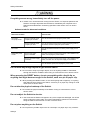
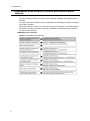
ALAXALA AX3800S/AX3600S/AX2400S Quick Start Guide AX36S-Q001-70X Reading and storing this manual: Before you use the equipment, carefully read the manual and make sure that you understand all safety precautions. After reading the manual, store it in a convenient place for easy reference. Relevant products This guide applies to the following: seven models in the AX2400S series (AX2430S-24T, AX2430S-24T2X, AX2430S-48T, AX2430S-48T2X, AX2430S-24TD, AX2430S-24T2XD, and AX2430S-48TD), 18 models in the AX3600S series (AX3630S-24T, AX3630S-24T2X, AX3630S-24P, AX3630S-24TD, AX3630S-24T2XD, AX3630S-24S2XW, AX3630S-48TW, AX3630S-48T2XW, AX3640S-24T, AX3640S-24TW, AX3640S-24T2XW, AX3640S-24SW, AX3640S-24S2XW, AX3640S-48TW, AX3640S-48T2XW, AX3650S-24T6XW, AX3650S-48T4XW, and AX3650S-20S6XW), and 1 model in the AX3800S series (AX3830S-44XW). Export restrictions Before exporting a switch, confirm all relevant restrictions, such as the Foreign Exchange and Foreign Trade Law of Japan, and the export control laws and regulations of the United States, and carry out all required procedures. If you require more information, please contact your ALAXALA sales representative. Trademarks - Ethernet is a registered trademark of Xerox Corporation. - Windows is a registered trademark of Microsoft Corporation in the United States and other countries. - Other product and company names mentioned in this document are the trademarks of their respective owners. Reading and storing this guide Before using the product, carefully read the manual and make sure that you understand all safety precautions. After reading the guide, keep it in a convenient place for easy reference. Note The information in this guide is subject to change without notice. Radio interference This is a Class A product. In a domestic environment, this product might cause radio interference, in which case the user may be required to take adequate measures. VCCI-A Harmonic regulations Products to which the harmonic current emissions standard JIS C 61000-3-2 applies Applicable products: AX2430S-24T AX2430S-24T2X AX2430S-48T AX2430S-48T2X AX3630S-24T AX3630S-24T2X AX3630S-24P AX3630S-24S2XW AX3630S-48TW AX3630S-48T2XW AX3640S-24T AX3640S-24TW AX3640S-24T2XW AX3640S-24SW AX3640S-24S2XW AX3640S-48TW AX3640S-48T2XW AX3650S-24T6XW AX3650S-48T4XW AX3650S-20S6XW AX3830S-44XW EPU-A EPU-B Edition history December 2005 (Edition 1), AX36S-Q001X (obsolete) December 2005 (Edition 2), AX36S-Q001-10X (obsolete) July 2006 (Edition 3), AX36S-Q001-20X (obsolete) January 2007 (Edition 4), AX36S-Q001-30X (obsolete) April 2007 (Edition 5), AX36S-Q001-40X (obsolete) November 2007 (Edition 6), AX36S-Q001-50X (obsolete) January 2011 (Edition 7), AX36S-Q001-60X (obsolete) August 2011 (Edition 8), AX36S-Q001-70X Copyright Copyright (C) 2005, 2011, ALAXALA Networks Corporation. All rights reserved. Preface Thank you for choosing an AX2400S series switch (ALAXALA compact gigabit Layer 2 switch), an AX3600S series switch (ALAXALA compact gigabit Layer 3 switch), or an AX3800S series switch (ALAXALA compact 10-gigabit Layer 3 switch). This guide describes the procedures from unpacking to the basic configuration of an AX3800S, AX3600S or AX2400S series switch. In addition, the guide also explains how to use the manuals for the AX3800S, AX3600S and AX2400S series switches to ensure stable operation of the switch. Guide overview Set up your switch by referring to the following flow of operations. Intended readers This document is intended for the technical personnel responsible for setting up and handling AX3800S, AX3600S and AX2400S series switches. Readers are therefore required to have knowledge of electric circuits, wire connections, and network systems. Conventions: The terms "Switch" and "switch" The term Switch (upper-case "S") is an abbreviation for any or all of the following models: AX2400S series switch AX3600S series switch AX3800S series switch The term switch (lower-case "s") might refer to a Switch, another type of switch from the current vendor, or a switch from another vendor. The context decides the meaning. I Preface II Contents Preface ................................................................................................................................................. I Safety Information .................................................................................................................Safety-1 1. Preparations .................................................................................................................................. 1 1.1 Organization of the AX3800S, AX3600S and AX2400S series manuals ............................ 2 1.2 Viewing the AX3800S, AX3600S and AX2400S series manuals ........................................ 5 1.3 Verifying supplied components ........................................................................................... 6 1.4 Preparing a setup terminal and cables ................................................................................ 7 2. Installing a Switch ......................................................................................................................... 9 2.1 Installing a Switch ..............................................................................................................10 2.1.1 Installing only the Switch ...................................................................................... 10 2.1.2 Using an EPU ...................................................................................................... 32 2.2 Other preparations ............................................................................................................51 3. Operations Required for Initial Installation ..............................................................................53 3.1 Overview of the command input modes ............................................................................54 3.2 Overview of initial setup operations ..................................................................................56 3.3 Login ..................................................................................................................................57 3.4 Setting the administrator mode password .........................................................................58 3.5 Adding a user ID and deleting the operator user ID ..........................................................59 3.6 Setting the time .................................................................................................................60 4. Other Operations ........................................................................................................................61 4.1 Detailed operations of the Switch ......................................................................................62 4.2 Troubleshooting .................................................................................................................64 i Contents ii Safety Information Using AX3800S, AX3600S and AX2400S series switches properly and safely This guide provides important information for ensuring safe use of AX3800S, AX3600S and AX2400S series switches. Please read this guide completely before using the Switches. Keep this manual handy after reading it, so that it is available for later reference. Operate the Switch according to the instructions and procedures provided in this manual. Heed all warnings and cautions regarding the Switch in this guide. Failure to do so could result in injury or damage to the Switch. Before using the Switch Caution indications These indications are intended to ensure safe and correct use of the Switch and to prevent serious injury, and equipment and property damage. Caution information in this manual and on the Switch is preceded by the indications shown below. Make sure you fully understand the meaning of the indications before continuing with the main body of this manual. Ignoring instructions preceded by this indication and using the Switch incorrectly could result in death or serious injury to yourself and others. Ignoring instructions preceded by this indication and using the Switch incorrectly could result in serious injury to yourself and others. CAUTION Ignoring instructions preceded by this indication and using the Switch incorrectly could result in serious damage to the Switch or nearby property. NOTE Information preceded by this indication is supplementary information that, if ignored, will not result in physical injury or serious damage to the Switch. Unauthorized operations Do not attempt to perform any operations that are not described in this guide. In the event of a Switch problem, turn off the power, unplug the power cable, and contact maintenance personnel. Using common sense The warnings and cautions provided on the Switch and in this guide have been selected after careful consideration. Nevertheless, there is always the possibility of the unexpected occurring. Therefore, while using a Switch, stay alert and use common sense in addition to all following instructions. Safety-1 Safety Information If anything seems wrong, immediately turn off the power. If smoke or an unusual smell is coming from the Switch, or if liquid is spilled into the Switch or a foreign object falls into the Switch, immediately turn off power to the Switch as described below. Continuing operation could result in a fire or electric shock. Actions to take for abnormal conditions Abnormal condition AC model AC (PoE) model Action to take When an external power unit (EPU) is not used Turn off the Switch and unplug the power cable. When an external power unit (EPU) is used Turn off the Switch and the power module supplying power to the Switch, and then unplug the power cables. DC model Turn off the Switch and then turn off the power supply circuit breaker. Redundant power model EPU When an AC power supply is installed Turn off the power to all the power supply units installed in the Switch, and unplug the power cables. When a DC power supply is installed Turn off the power to all the power supply units installed in the Switch, and then turn off the power supply circuit breaker. Turn off the EPU power, and unplug the power cable. Do not allow any foreign objects to get into the Switch. Do not insert or drop any foreign objects, such as anything metallic or flammable, through the Switch's ventilation slots. Doing so could result in fire or electric shock. When pressing the RESET button, do not use anything with a fragile tip, or anything that might become caught in the Switch, such as a pin or paper clip. When pressing the RESET button, do not use anything with a fragile tip, or anything that might become caught in the Switch, such as a pin or paper clip. Doing so could result in fire or electric shock. Do not alter the physical makeup of the Switch. Do not alter the physical makeup of the Switch. Doing so could result in a fire or electric shock. Do not subject the Switch to shocks. In the event that the Switch is dropped or any of its components damaged, turn off the power, unplug the power cable, and contact maintenance personnel. Discontinue using the cable to avoid the risk of a fire or electric shock. Do not place anything on the Switch. Do not place any metallic object such as a small pin or a paper clip or any container Safety-2 Safety Information with a liquid, such as a vase or a flower pot, on the Switch. Liquid or metallic objects falling into the Switch could result in a fire or electric shock. Safety-3 Safety Information Use the Switch only with the indicated power supply setting. Do not use the Switch at any voltage other than the indicated voltage. Doing so could result in a fire or electric shock. Ensure that the capacity for incoming current to the distribution board is greater than the operating current of the circuit breaker. Ensure that the capacity for incoming current to the distribution board is greater than the operating current of the circuit breaker. If it is not, the circuit breaker might not operate properly in the event of a failure, which could result in a fire. Ground the Switch. When using an AC (PoE) model, redundant power model (with an AC power supply module installed), and an EPU, use only a grounded power outlet. Failure to do so might not only result in electric shock, but it might also introduce unwanted electrical noise that could cause a Switch failure. When using a DC model and a redundant power model (with a DC power supply module installed), connect a ground cable to ground the Switch. Failure to do so might not only result in electric shock, but it might also introduce unwanted electrical noise that could cause a Switch failure. Mounting and removing the −48 V DC power cable must be done by a trained technician or maintenance personnel. Mounting and removing the −48 V DC power cable must be done by a trained technician or maintenance personnel. Terminal connections are required for connection of the −48 V DC power cable to the power facility. For this reason, incorrect handling of the −48 V DC power cable could result in fire or electric shock. Make sure the power supply circuit breaker is set to OFF before connecting or disconnecting a −48 V DC power cable. Make sure the power supply circuit breaker is set to OFF before connecting or disconnecting a −48 V DC power cable. Connecting or disconnecting the cable with the circuit breaker set to ON could result in a fire or electric shock. Place an insulation cover over the G and −48 V terminals of a −48 V DC power cable Place an insulation cover to the G and −48 V terminals of a −48 V DC power cable (on the side grounded to the power supply). Using the terminals without an insulation cover could result in electric shock. Safety-4 Safety Information Observe the specified stripping length of the sheath for the power cable. When using a DC −48 V power cable for a redundant power model, adjust the stripping length of the sheath for the power cable (the Switch end) to 8 to 10 mm. If the striping length is too short, connection might fail or the cable might become disconnected. Conversely, if the length is too long, the core will be exposed, risking electric shock. Do not use the Switch with the protection cap removed. Do not remove the protection cap except when attaching a cable. Using the Switch with no protection cap could result in a fire or electric shock. Note that the following label is affixed near the standby power connector due to the high output power of EPU-B. Handle power cables carefully. Do not place anything heavy on a power cable. Do not pull, bend, or modify a cable. Doing so could damage the cable, resulting in a fire or electric shock. If the power cable is covered by a carpet, it is easy to forget that the cable is there and to place something heavy on it. Use the supplied or a designated power cable. Using another power cable could result in a fire or electric shock. Do not use a power cable supplied with a product other than this product. Doing so could result in a fire or electric shock. If the power cable is damaged so that the wires underneath the covering are visible or cut, stop using it, and ask maintenance personnel to replace it. Discontinue using the cable to avoid the risk of a fire or electric shock. Make sure the power plug is free of dust, and insert the plug completely up to the base of the prongs, so that it is not loose. Using a power plug with dust on it or one that is imperfectly connected could result in a fire or electric shock. Do not overload the power outlet. Do not overload the power outlet by connecting multiple power plugs to the same outlet. Overloading the outlet could result in fire or the circuit breaker tripping due to excessive power used, which can then affect other equipment. Remove the power cable when installing or removing a power supply unit. When installing or removing a power supply unit, remove the power cable from the power supply unit. If the power cable is connected and the power switch is turned off, power is still supplied to some circuits. Because of this, if you install or remove a power supply unit with the power cable connected, a fire or electric shock could result. Safety-5 Safety Information Do not use an air duster near a flame. When cleaning the optical connectors, do not use an air duster that contains flammable gas near a flame. Doing so could result in a fire. Safety-6 Safety Information Do not place the Switch in a place where it is unstable. If placing the Switch on a desk, lay it on its side on a workbench capable of withstanding the weight of the Switch. If, for example, you place the Switch on a shaky table or a tilted surface, the Switch might fall and possibly injure someone. When installing the Switch in a rack, make sure the Switch in the rack is stably positioned. If the Switch is not positioned correctly, injury could result from falling equipment or stumbling over the equipment. Do not remove the Switch cover. Do not remove the Switch cover. Doing so could result in electric shock. The following label is affixed to a Switch. Do not block the ventilation slots. Do not cover the ventilation slots of the Switch. Doing so causes heat to accumulate inside the Switch and could result in a fire. Leave at least 50 mm of space in front of ventilation slots. Do not allow hair or objects near the ventilation slots. Because cooling fan units are mounted in the Switch, do not allow anything near the ventilation slot. Doing so causes heat to accumulate inside the Switch and could cause a failure. Do not allow hair or other objects near the ventilation slots because they might be sucked into the Switch, resulting in injury. When moving the Switch, do not hold the handle of the power supply unit, fan unit, or power supply module. When moving a redundant power model, do not hold the handle of the power supply unit or the fan unit. The handle might come off, resulting in the Switch falling and possibly causing injury. In addition, the module might become damaged, resulting in a fire or electric shock. When moving an EPU, do not hold the handle of the power supply module. The handle might come off, resulting in the Switch falling and possibly causing injury. In addition, the module might become damaged, resulting in a fire or electric shock. Safety-7 Safety Information When moving the Switch Before moving the Switch, you must turn it off and unplug all cables. Failure to do so might cause the Switch or cable to become damaged, resulting in a fire or electric shock. If you must stack multiple switches during transport, use appropriate packaging. Failure to do so might cause the Switch to become deformed or damaged, resulting in a fire or electric shock. Handle the power cable carefully. Do not place the power cable near a heat-generating apparatus. The heat could melt the cable coating, resulting in fire or electric shock. When connecting or disconnecting the AC power cable from the outlet, always hold the plug, not the cable itself. Pulling the cable might cause the wires to break. When connecting or disconnecting the DC power cable, always hold the connector of the cable. Pulling the cable itself might cause the wires to break. Safety-8 Safety Information When turning off the power, stop the supply of all power to the Switch. If power is supplied to an AC model and an AC (PoE) model from an EPU, switch power cannot be turned off by setting just the power switch of the Switch to OFF. To turn off the Switch, set the power switch of both the switch and the power module to OFF. If the power supply for a redundant power model has been made redundant, the Switch cannot be turned off by setting just the power switch of either power supply unit to OFF. To turn off the Switch, set the power switch of all power supply units installed for the Switch to OFF. Do not touch the Switch directly if you have a metal allergy. The Switch is coated with zinc, nickel, gold, and other elements. Do not touch the Switch directly if you have an allergic reaction to these metals. Doing so might cause eczema or skin irritation. Avoid looking directly at laser beams. The Switch uses laser beams that are colorless and transparent, and invisible to the eye. Never look directly into the optical transceiver. Do not touch SFP-T and SFP-T (T) during operation and just after operation stops. During operation (when a link is established), the temperature of SFP-T and SFP-T(T) can rise to 65C. Do not touch an SFP-T or SFP-T (T) while they are running or right after they are stopped. Doing so could result in a burn. Use the procedure below to remove an SFP-T or SFP-T (T). Failure to do so could result in burns. To remove the SFP-T(T) when the Switch is turned on, block the SFP slot, and then wait 5 minutes before removing the SFP-T(T). To remove the SFP-T(T), turn off the Switch and then wait five minutes. The following label is affixed to SFP-T and SFP-T (T). Safety-9 Safety Information Do not install the Switch in a dusty or humid location. Do not install the Switch in a dusty or humid location. Doing so could result in fire or electric shock. Condensation might form on the surfaces and the inside of the Switch if it is moved from a cold location to a warm location. Using the Switch in this condition could result in fire or electric shock. After moving the Switch between two locations with a large temperature variation, let the Switch stand a few hours before using it. Do not step on the Switch, lean against it, or place anything on it. Do not step on the Switch, lean against it, or place anything on it. Doing so might damage the Switch. Furthermore, the Switch might fall or lose its balance, resulting in injury. Do not place anything that weighs more than 5 kg on the Switch. Doing so might damage the Switch. Furthermore, the Switch might fall or lose its balance, resulting in injury. Do not touch the inside of the Switch with your hands. Do not carelessly put your hands inside the Switch. The frame and components might cause injury. Install fan units into slots of a redundant power model that do not contain power supply units (AX3630S and AX3640S series models). Install a fan unit for the slot of a redundant power model without power supply units (AX3630S and AX3640S). If you use the Switch without installing a fan unit, one of the following errors might occur: - The temperature inside the Switch will rise and can cause a failure. - You might be injured by a moving part. - A foreign object might fall into the Switch, causing a failure. - The electronic interference generated by the Switch affects other devices and vice versa, which can cause a failure. Install fan units into slots of a redundant power model that do not contain power supply units (AX3830S and AX3650S series models). Install a fan unit for the slot of a redundant power model without power supply units (AX3830S and AX3650S). If you use the Switch without installing a blank panel, one of the following errors might occur: - The temperature inside the Switch will rise and can cause a failure. - You might be injured by a moving part. - A foreign object might fall into the Switch, causing a failure. - The electronic interference generated by the Switch affects other devices and vice versa, which can cause a failure. Safety-10 Safety Information Attach a blank panel to a slot in which a power supply module of an EPU is not installed. Be sure to attach a blank panel to any slots for which a power supply module for an EPU is not installed. If you use the Switch without attaching the blank panel, you might be injured by a moving part. In addition, if foreign objects fall into the Switch, the Switch might no longer work properly. Cleaning Remove dust on and around the Switch regularly. In addition to possibly causing the Switch to stop, accumulated dust might result in fire or electric shock. Safety-11 Safety Information Do not place the Switch in a high-temperature location. Do not place the Switch in direct sunlight or near a heater or other heat-generating apparatus. Doing so could adversely affect parts of the Switch. Do not use a TV or a radio near the Switch. Placing the Switch near a TV or a radio could affect both devices. If you hear noise on the TV or radio, do the following: - Place the Switch as far away as possible from the TV or radio. - Adjust the orientation of the TV or radio antenna. - Use separate outlets. Do not place the Switch in an undesirable environment. Using the switch in the following locations might shorten the life of the switch or result in a switch malfunction. - An area with salty air, such as the coast - An area where corrosive gases are present, such as a hot-springs area - An area where oily smoke is present - An area where continuous vibrations are present Ensure that voltage drop does not occur in the power facility due to an inrush current. Turning on the Switch causes an inrush current. Ensure that voltage drop does not occur in the power facility due to the inrush current. Voltage drops affect not only the Switch, but also the devices connected to the same electrical power equipment. Turn off the power before connecting or disconnecting the power cable. Turn off the power of the Switch before connecting or disconnecting the power cable of an AC model, equipment for an AC (PoE) model, and an EPU model. Turn off the power of a power supply unit before connection or disconnection of the power cable or the connector of the cable for a redundant power model. For a standby power cable, turn off the power of the power supply module first. Safety-12 Safety Information When replacing a power supply unit or a fan unit with the Switch turned on, observe the time limit. When performing a replacement as shown below with the Switch turned on, you must remove and replace a unit within three minutes. If the operation takes longer than three minutes, the temperature inside the Switch will rise and can cause a failure. When replacing a power supply unit or a fan unit on redundant power models (AX3630S and AX3640S series models) When replacing a fan unit on a redundant power model (AX3650S series models) When performing a replacement as shown below with the Switch turned on, you must remove and replace a unit within one minute. If the operation takes longer than one minute, the temperature inside the Switch will rise and can cause a failure. When replacing a fan unit on a redundant power model (AX3830S series models) Turn off the power before installing or removing a power supply module. Before installing or removing a power supply module, turn off its power. Installing or removing the module with the power supply module turned on causes a (Switch) failure. The following label is attached to the EPU. Turn off the power of the power supply modules before turning on the main power switch of an EPU. Before setting the main power switch of the EPU to ON, you must set the power switches of the installed power supply modules to OFF. Do not turn off the main power switch of an EPU if the standby power supply unit is used for the Switch. Turning off the main power switch of an EPU stops the supply of all standby power to the Switch. Do not turn off the main power switch if a standby power supply unit is being used for the Switch. Safety-13 Safety Information Handle memory cards and dummy memory cards carefully. When installing a memory card and a dummy memory card, do not force the card. When removing a memory card, do not forcibly pull out the card if it is locked. Doing so might damage the connector of the memory card slot. When moving the Switch, remove memory cards and dummy memory cards. If a card is subjected to excessive force when the switch is moved, the connector of the memory card slot might be damaged. When the ACC LED is lit, do not remove the memory card or turn off the power. When the ACC LED on the front panel of the Switch is lit, the memory card is being accessed. When a memory card is being accessed, do not remove the memory card or turn off the power. Doing so might damage the memory card. In addition, some commands require a certain amount of time after being entered to finish accessing the card. Make sure that the memory card is no longer being accessed before removing the card or turning off the power. Do not attach any labels to a transceiver or a direct attach cable connector. A label attached to the transceiver or direct attach cable connector indicates that the transceiver or direct attach cable connector is a standard product from ALAXALA or another manufacturer. However, such labels are attached where they do not interfere with heat dissipation from the transceiver or from the direct attach cable connector or interfere with the mechanism that prevents the transceiver or the direct attach cable connector from coming loose from the cage. Attaching a label to a location that interferes with these functions could cause a malfunction in the transceiver or a direct attach cable connector, or cause damage to the Switch. Make sure that you use the correct direct attach cables for the Switch. The switches below support SFPP-CU1M/3M/5M. Do not use them on other switches. Doing so could result in a Switch failure. - AX3650S-24T6XW (ports 25 to 30) - AX3650S-20S6XW (ports 25 to 30) - AX3650S-48T4XW (ports 49 to 52) - AX3830S-44XW (ports 1 to 44) Safety-14 Safety Information Make sure that you use a valid combination for the transceiver and the Switch. The switches below support SFP-FX and SFP-FX (T). Use the transceiver only with the indicated switches. Not doing so could result in a Switch malfunction. - AX3640S-24SW (ports 5 to 24) - AX3640S-24S2XW (ports 5 to 24) - AX3650S-20S6XW (ports 1 to 20) The switches below support SFP-SX2 and SFP-SX2 (T). Use the transceiver only with the indicated switches. Not doing so could result in a Switch malfunction. - AX2430S series switches - AX3630S series switches - AX3640S series switches - AX3650S-20S6XW (ports 1 to 20) Do not turn off the Switch while the ST1 LED is blinking in green (on: 0.5 seconds, off: 0.5 seconds). For the period below, do not turn off the Switch until the ST1 LED on the front panel of the Switch changes from blinking green (on: 0.5 seconds, off: 0.5 seconds) to a constant green. Failure to do so could result in a switch failure. While software is being updated When carrying or packing a Switch and an optional module, wear a wrist strap to protect against static electricity. Be sure to wear an antistatic wrist strap. If you handle the Switch without wearing an antistatic wrist strap, the Switch might be damaged by static electricity. When carrying and packing optional modules, handle them carefully. Do not touch a connector when carrying or packing a transceiver, direct attach cable, memory card, power supply unit, fan unit, or power module. Also, when storing a module, use an antistatic bag. Use care when handling an air duster. Use an air duster specially designed for cleaning optical connectors. Using another type of air duster could cause the ferrule tip to become dirty. Keep the nozzle or container of the air duster from coming into contact with the ferrule tip. Contact could result in a malfunction. Safety-15 Safety Information Use care when handling an optical connector cleaner. Always use a dedicated optical connector cleaner. If you use another type of cleaner, the ferrule tip might become dirty. Before cleaning, make sure that the tip of the optical connector cleaner is clean and free of defects, such as lint, dirt, or other foreign substances. Using a cleaner with a defective tip might damage the ferrule tip. Do not apply excessive pressure when cleaning. Doing so might damage the ferrule tip. Rotate the optical connector cleaner (stick) clockwise only. Rotating the cleaner alternately clockwise and counterclockwise might damage the ferrule tip. Maintenance Clean any dirty areas on the exterior of the switch with a clean, dry cloth, or a cloth damp with (but not soaked with) water or a neutral detergent. Do not use volatile organic solutions (such as benzene or paint thinner), chemicals, chemically treated cloths, or pesticides because these substances might deform, discolor, or damage the switch. If the Switch will not be used for a long time For safety reasons, unplug the power cable from the outlet if the Switch will not be used for a long time. If you are using a DC power supply, turn off the circuit breaker at the supply of power. Disposing of a Switch When disposing of a switch, you should either follow local ordinances or regulations or contact your local waste disposal and treatment facility. Safety-16 1. Preparations This chapter describes the preparations necessary for using the Switch. It also describes the manual organization for AX2400S and AX3600S series switches, where this guide is in that manual organization, and where the manuals can be viewed from. 1.1 Organization of the AX3800S, AX3600S and AX2400S series manuals 1.2 Organization of the AX3800S, AX3600S and AX2400S series manuals 1.3 Verifying supplied components 1.4 Preparing a setup terminal and cables 1 1. Preparations 1.1 Organization of the AX3800S, AX3600S and AX2400S series manuals The figures below provide an overview of the AX3800S, AX3600S and AX2400S series manuals. This Quick Start Guide explains only the operations from unpacking the Switch to setting it up for basic operation. Note that this guide provides only a minimum amount of information. To take advantage of the wealth of functions provided by AX3800S, AX3600S, and AX2400S series switches, see the following manuals. AX2400S series manuals Figure 1-1 AX2400S series manuals 2 1. Preparations AX3640S and AX3630S series manuals Figure 1-2 AX3640S and AX3630S series manuals 3 1. Preparations AX3800S and AX3650S series manuals Figure 1-3 AX3800S and AX3650S series manuals 4 1. Preparations 1.2 Viewing the AX3800S, AX3600S and AX2400S series manuals The AX3800S, AX3600S, and AX2400S series manuals are available on the ALAXALA website at the following address: http://www.alaxala.com/en/index.html 5 1. Preparations 1.3 Verifying supplied components Use the packing list to verify that all components and accessories are present. NOTE 6 A packing list is also provided for optional components, such as power supplies, fan units, EPUs, power supply modules, and transceivers. If you purchased an optional component, check that packing list as well. 1. Preparations 1.4 Preparing a setup terminal and cables To set up the Switch, prepare the following in addition to the Switch, components, and accessories. Setup terminal Prepare a personal computer or a workstation that supports the specifications in the following table. Table 1-1 Setup terminal specifications Item Specification Communication port RS-232C port Communication software Tera Term Pro (Version 2.3) or communication software that supports the following communication settings. Communication settings Transfer protocol ZMODEM procedure Communication parameters 8 bits, 1 stop bit, no parity Communication #1 speed 19,200 bit/s, 9,600 bit/s, 4,800 bit/s, 2,400 bit/s, 1,200 bit/s Other CD-ROM drive #2 #1: The CONSOLE port of the Switch is set to 9,600 bit/s when shipped from the factory. #2: Used for installing option licenses. RS-232C cross cable To connect the setup terminal to the Switch, use an RS-232C cross cable with a 9-pin (female) D-SUB connector and with inch screws (#4-4) on both ends. You can purchase this cable at any electronics store. The following figure shows the pin arrangement of an RS-232C cross cable. Figure 1-4 Pin arrangement of an RS-232C cross cable Interface cable An interface cable is necessary to connect to other devices. For details about interface cables, see the AX3800S/AX3600S/AX2400S Hardware Instruction Manual. 200 V AC power cable When an AC model and a redundant power model are used at 200 V AC, a 200 V AC power 7 1. Preparations cable is required. For details about preparing a 200 V AC power cable, see the AX3800S/AX3600S/AX2400S Hardware Instruction Manual. DC power cable If a redundant power model (an AX3630S or AX3640S series model) is used at −48 V DC, a DC power cable is required. For details about preparing a DC power cable, see the AX3800S/AX3600S/AX2400S Hardware Instruction Manual. 8 2. Installing a Switch This chapter describes the procedure for installing the Switch into a 19-inch cabinet rack and turning on the power. 2.1 Installing a Switch 2.2 Other preparations 9 2. Installing a Switch 2.1 Installing a Switch This section describes the procedure for installing the Switch into a 19-inch cabinet rack and turning on the power. 2.1.1 Installing only the Switch [Step 1] Installing the Switch Use the following procedure to install a Switch into a 19-inch cabinet rack. When moving a redundant power model, do not hold the handle of the power supply unit or the fan unit. The handle might come off, resulting in the switch falling and possibly causing injury. In addition, the module might become damaged, resulting in a fire or electric shock. NOTE NOTE NOTE 10 When placing the EPU on a desk, see the AX3800S/AX3600S/AX2400S Hardware Instruction Manual. The supplied rack mounting brackets are designed for M5 screws. Prepare a rack that accommodates M5 screws. For AX3830S and AX3650 series switches, some space around the memory card slot is required for installation and removal. If the Switch is installed under another device, leave adequate space, keeping in mind that objects will protrude from the front of the device, such as optional parts and cables. 2. Installing a Switch 1. Attach the rack mounting brackets to the Switch. Figure 2-1 Attaching rack mounting brackets (AX2400S and AX3600S series switches) (1) Rack mounting bracket (L) (2) Rack mounting bracket (R) (3) Screws (M3 x 6 for each bracket, 12 screws in all) NOTE Rack mounting brackets are provided on the left and right sides. The left rack mounting bracket is marked with an " L", and the right with an " R". 11 2. Installing a Switch Figure 2-2 Attaching rack mounting brackets (AX3800S) (1) Front rack mounting bracket (L) (2) Front rack mounting bracket (R) (3) Rear rack mounting bracket (L) (4) Rear rack mounting bracket (R) (5) Rack mounting bracket for the rear mount (L) (6) Rack mounting bracket for the rear mount (R) (7) Screws (M4 x 6 for each bracket, 16 screws in all) (8) Screws (M3 x 8 for each bracket, 4 screws in all) NOTE Front rack mounting brackets, rear rack mounting brackets, and rack mounting brackets for the rear mount are provided on the left and right sides. The left-front rack mounting bracket is marked with an " FL", and the right-front mounting bracket with an " FR". The left-rear rack mounting bracket is marked with an " RL", and the right-rear mounting bracket with an " RR". The rack mounting brackets for the rear mounts are not marked, because they are same on both sides. NOTE For AX3800S series switches, the attachment position of the front and rear rack mounting brackets can be adjusted according to the distance between the front and rear posts (620 mm to 655 mm, 720 mm to 755 mm, 770 mm to 805 mm, and 820 mm to 855 mm). NOTE When installing the switch in a rack, if you cannot maintain a 100-mm space (for cables), slide the brackets 50 mm toward you and attach them as shown in the following figure. 12 2. Installing a Switch Figure 2-3 Attaching the rack mounting brackets by sliding them 50 mm forward (AX2400S and AX3600S) (1) Rack mounting bracket (L) (2) Rack mounting bracket (R) (3) Screws (M3 x 6 for each bracket, 12 screws in all) NOTE NOTE Use the supplied screws when attaching the rack mounting brackets to the EPU. Four types of rack mounting brackets are available: For the AC model and DC model: 12 screw holes For the AC model (PoE), redundant power models (AX3630S and AX3640S) and the EPU: 12 screw holes (with a label " 24P/EPU") For a redundant power model (AX3650S): 10 screw holes For a redundant power model (AX3830S): 20 screw holes Use the correct brackets when attaching brackets to a switch. 13 2. Installing a Switch 2. Install the Switch in the rack. Figure 2-4 Installing a Switch in the rack (AX2400S and AX3600S) (1) Screws (M5 x 4) (2) 19-inch cabinet rack 14 2. Installing a Switch Figure 2-5 Installing a Switch in the rack (AX3800S) (1) Screws (M5 x 8) (2) 19-inch cabinet rack Before installing an EPU in a rack, make sure the device is stable. If the switch is not positioned correctly, injury could result from falling equipment or stumbling over the equipment. NOTE NOTE When installing an EPU in a rack, use the supplied M5 screws. For AX3800S series switches, the attachment position of the front and rear rack mounting brackets can be adjusted according to the distance between the front and rear posts (620 mm to 655 mm, 720 mm to 755 mm, 770 mm to 805 mm, and 820 mm to 855 mm). 15 2. Installing a Switch [Step 2] Connecting a power cable to a Switch Connect a power cable to the Switch. Use an AC power cable for AC models, an AC (PoE) models, and redundant power models (when an AC power supply is installed). Use a DC power cable for DC models and redundant power models (when a DC power supply is installed). NOTE 16 When a switch is installed in a rack, use the cable holder supplied with the rack to fix the power cable in order to prevent stress on the cable base. 2. Installing a Switch AC power cable (AC model and AC (PoE) model) Connect the supplied power cable to the AC power connector on the rear of the Switch. Figure 2-6 Connecting the AC power cable (for an AC model and an AC (PoE) model) (1) Standby power connector (with a protection cap) (2) Cable clamp (3) AC power cable (4) AC power connector When using this switch at 100 V AC, use the supplied power cable. Using another cable could result in a fire or electric shock. In addition, do not use the supplied power cable with another switch. Doing so could result in a fire or electric shock. When using the switch at 200 V AC, use a power cable that satisfies the specified specifications. Using another power cable could result in a fire or electric shock. Always use a grounded outlet. Failure to do so might not only result in electric shock, but it might also introduce unwanted electrical noise that could cause a switch failure. Do not remove the protection cap except to connect a cable. Using a switch with no protection cap could result in a fire or electric shock. CAUTION Before connecting or disconnecting a power cable, use the power switch to turn the Switch off. 17 2. Installing a Switch NOTE For details about the specifications for the specified power cable, see the AX3800S/AX3600S/AX2400S Hardware Instruction Manual. AC power cable (redundant power models (AX3630S and AX3640S)) Connect power cables to all power supplies. (Connect the supplied power cable to the AC power connector on the rear of the Switch.) Figure 2-7 Connecting the AC power cable (redundant power models (AX3630S and AX3640S)) (1) Cable clamp (2) AC power cable (3) AC power connector When using this switch at 100 V AC, use the supplied power cable. Using another cable could result in a fire or electric shock. In addition, do not use the supplied power cable with another switch. Doing so could result in a fire or electric shock. When using the switch at 200 V AC, use a power cable that satisfies the specified specifications. Using another power cable could result in a fire or electric shock. Always use a grounded outlet. Failure to do so might not only result in electric shock, but it might also introduce unwanted electrical noise that could cause a switch failure. CAUTION 18 Before connecting or disconnecting a power cable, turn off the power to the device to be installed or removed. 2. Installing a Switch NOTE For details about the specifications for the specified power cable, see the AX3800S/AX3600S/AX2400S Hardware Instruction Manual. AC power cable (redundant power models (AX3650S and AX3830S)) Connect power cables to all power supplies. (Connect the supplied power cable to the AC power connector on the rear of the Switch.) Figure 2-8 Connecting the AC power cable (redundant power models (AX3650S and AX3830S)) (1) Cable clamp (2) AC power cable (3) AC power connector When using this switch at 100 V AC, use the supplied power cable. Using another cable could result in a fire or electric shock. In addition, do not use the supplied power cable with another switch. Doing so could result in a fire or electric shock. When using the switch at 200 V AC, use a power cable that satisfies the specified specifications. Using another power cable could result in a fire or electric shock. Always use a grounded outlet. Failure to do so might not only result in electric shock, but it might also introduce unwanted electrical noise that could cause a switch failure. CAUTION NOTE Before connecting or disconnecting a power cable, turn off the power to the device to be installed or removed. For details about the specifications for the specified power cable, see the AX3800S/AX3600S/AX2400S Hardware Instruction Manual. 19 2. Installing a Switch DC power cable (DC model) Use the supplied power cable. Using another cable could result in a fire or electric shock. Do not use a power cable supplied with a product other than this product. Doing so could result in a fire or electric shock. Connecting or disconnecting the DC power cable to the power supply unit must be performed by a trained technician or maintenance personnel. Terminal connections are required for connection of the DC power cable to the power facility. For this reason, incorrect handling of the DC power cable could result in fire or electric shock. Before connecting or disconnecting a DC power cable, turn off the power. Failure to do so could result in a fire or electric shock. The DC power cable is supplied with no cable end treatment on the power supply unit side. Apply appropriate terminal treatment such as connecting terminals appropriate for the power supply unit. For details about DC power cables, see the AX3800S/AX3600S/AX2400S Hardware Instruction Manual. NOTE 1. Connect the ground cable to the Switch. Figure 2-9 Connecting the ground cable (1) Screws (M4 x 8) (2) Ground cable (3) Ground terminal Always connect the ground terminal for proper grounding. Failure to do so might not only result in electric shock, but it might also introduce unwanted electrical noise that could cause a switch failure. 2. 20 Connect the supplied power cable to DC power connector 1 on the rear of the Switch (push the connector until you hear a click). 2. Installing a Switch Figure 2-10 Connecting the DC power cable (1) DC power connector 2 (with the protection cap) (2) DC power cable (3) DC power connector 1 Do not remove the protection cap except to connect a cable. Using a switch with no protection cap could result in a fire or electric shock. NOTE An optional DC power cable is required to have redundant power supply units. For this operation, remove the protection cap on DC power connector 2, and connect a DC power cable. Make sure you keep the removed protection cap in a safe place. 21 2. Installing a Switch DC power cable (redundant power models (AX3630S and AX3640S series models)) Use the specified DC power cable. Using another power cable could result in a fire or electric shock. Connecting and disconnecting a DC power cable must be performed by a trained technician or maintenance personnel. Before connecting or disconnecting a DC power cable, turn off the power. Failure to do so could result in a fire or electric shock. NOTE For details about the specifications for the specified power cable, see the AX3800S/AX3600S/AX2400S Hardware Instruction Manual. 1. Connect the ground cable to the Switch. Figure 2-11 Connecting the ground cable (1) Screws (M4 x 8) (2) Ground cable (3) Ground terminal Always connect the ground terminal for proper grounding. Failure to do so might not only result in electric shock, but it might also introduce unwanted electrical noise that could cause a switch failure. NOTE 22 Ground cables are supplied with no cable end treatment on the power supply unit side. Apply appropriate terminal treatment such as connecting terminals appropriate for the power supply unit. For details about ground cables, see the AX3800S/AX3600S/AX2400S Hardware Instruction Manual. 2. Installing a Switch 2. *Remove the connector cable from the power supply unit (pull the connector while holding the right and left levers). Figure 2-12 Removing the cable connector (1) Cable connector (2) Power supply unit 3. *Connect the DC power cable to the cable connector. Press the button with the tip of a screwdriver (pushing the button all the way in causes it to stay like that). Figure 2-13 Connecting the DC power cable - 1 (1) Button (white) (2) −48V (3) 0 V (4) Button (red) 23 2. Installing a Switch 4. *Insert the power cable, and return the buttons to their original positions (the power cable is clamped). Figure 2-14 Connecting the DC power cable - 2 (1) DC power cable (2) −48V (3) 0V Adjust the stripping length of the sheath for the DC power cable (on the switch end) to 8 to 10 mm. If the stripping length is too short, connections might fail or the cable might become disconnected. Conversely, if the length is too long, the core will be exposed, risking electric shock. 24 2. Installing a Switch 5. *Attach the cable connector to the power supply unit (push the connector until you hear a click). Figure 2-15 Attaching the cable connector (1) Cable connector (2) DC power connector (3) Power supply unit CAUTION NOTE Before attaching or removing the cable connector, turn off the power supply unit. To make the power supply units redundant, perform steps 2* to 5* to connect a power cable to the other power supply unit. 25 2. Installing a Switch [Step 3] Installing a dummy memory card Insert a dummy memory card (hereafter, dummy card) until you hear a click, and then gently remove your fingers. (Insert the dummy card with the notch facing left.) Figure 2-16 Installing a dummy card (1) Dummy card (2) Memory card slot CAUTION NOTE 26 When installing a dummy card, do not force the card or pinch it with your fingers. Doing so could break the memory card slot connector. Before installing a memory card, remove any dust in and around the memory card slot with a dry cloth. 2. Installing a Switch [Step 4] Installing a transceiver If you purchased a transceiver, install it. Insert the transceiver with the lever raised as shown in the following figure until you hear a click. Figure 2-17 Installing a transceiver (upper port) (1) SFP (2) SFP slot NOTE NOTE The above figure is an example of when an SFP transceiver is installed into the upper SFP slot of a model with two SFP slots. For models with one SFP slot, install a transceiver in the direction shown in the figure. Note, however, that when installing a transceiver in the lower SFP slot of models with two SFP slots, turn the transceiver upside down and install it as shown in the figure below. Use the same procedure to install an SFP+ transceiver into an SFP+ slot and to install an XFP transceiver into an XFP slot. Figure 2-18 Installing a transceiver (lower port) (1) SFP (2) SFP slot [Step 5] Connecting the setup terminal Connect the setup terminal to the Switch. 27 2. Installing a Switch 1. Connect the setup terminal to the CONSOLE port of the Switch. Use an RS-232C cross cable for the connection. Figure 2-19 Connecting a setup terminal (1) Setup terminal (2) RS-232C cross cable (3) CONSOLE port NOTE After the setup terminal is connected to the port, tighten the screws. Also make sure the terminal is firmly connected. NOTE NOTE 28 For details about RS-232C cross cables, see 1.4 Preparing a setup terminal and cables. 2. Start the setup terminal. 3. Start the communication software. 4. Configure the communication software. For details about the communication parameters, see 1.4 Preparing a setup terminal and cables. For details about how to configure the communication software, see the documentation for the communication software. 2. Installing a Switch [Step 6] Connecting an interface cable Connect the interface cable to the interface port. NOTE For a PoE connection, if you disconnect and then re-connect a UTP cable within two seconds of connecting the cable, the power class of the equipment on the power-receiving side might not be recognized correctly. When removing and re-connecting the cable, be sure to wait for at least two seconds. [Step 7] Turning on the power Set the power switch of the Switch to ON. Figure 2-20 Turning on the power (AC model and AC (PoE) model) (1) Power switch Figure 2-21 Turning on the power (DC model) (1) Power switch 29 2. Installing a Switch Figure 2-22 Turning on the power (redundant power models (AX3630S and AX3640S series models)) (1) Power switch NOTE When redundant power supplies are installed for a redundant power model, if only one of the power switches is set to ON, a power supply error might be detected (and the ST1 LED will blink red). Setting both power switches to ON removes the error state. Figure 2-23 Turning on the power (redundant power models (AX3650S and AX3830S series models)) (1) Power switch NOTE 30 When redundant power supplies are installed for a redundant power model, if only one of the power switches is set to ON, a power supply error might be detected (and the ST1 LED will blink red). Setting both power switches to ON removes the error state. 2. Installing a Switch [Step 8] Checking the LEDs If the ST1 LED on the front panel of the Switch turns green, the Switch is running. For details about the process for starting a Switch, see 2.2 Other preparations. Figure 2-24 Checking the LEDs NOTE NOTE For details about the process until the switch is started, see 2.2 Other preparations. If the red ST1 LED is blinking or on, a switch failure has occurred. If a switch failure occurs, see the AX6700S/AX6600S/AX6300S/AX3800S/AX3600S/AX2400S Troubleshooting Guide and take appropriate action. 31 2. Installing a Switch 2.1.2 Using an EPU [Step 1] Installing the Switch Install the Switch in a 19-inch cabinet rack. NOTE When placing the EPU on a desk, see the AX3800S/AX3600S/AX2400S Hardware Instruction Manual. NOTE The supplied rack mounting brackets are designed for M5 screws. Prepare a rack that accommodates M5 screws. 1. Attach the rack mounting brackets to the Switch. Figure 2-25 Attaching rack mounting brackets to the Switch (1) Rack mounting bracket (L) (2) Rack mounting bracket (R) (3) Screws (M3 x 6 for each bracket, 12 screws in all) NOTE 32 When installing the switch in a rack, if you cannot maintain a 100-mm space (for cables), slide the brackets 50 mm toward you and attach them as shown in the following figure. 2. Installing a Switch Figure 2-26 Attaching rack mounting brackets to the Switch (brackets moved 50 mm forward) (1) Rack mounting bracket (L) (2) Rack mounting bracket (R) (3) Screws (M3 x 6 for each bracket, 12 screws in all) NOTE NOTE NOTE Use the supplied screws when attaching the rack mounting brackets to the EPU. Four types of rack mounting brackets are available: For the AC model and DC model: 12 screw holes For the AC model (PoE), redundant power models (AX3630S and AX3640S series models) and the EPU: 12 screw holes (with a label " 24P/EPU") For a redundant power model (AX3650S): 10 screw holes For a redundant power model (AX3830S): 20 screw holes Use the correct brackets when attaching brackets to a switch. Rack mounting brackets are provided on the left and right sides. The left rack mounting bracket is marked with an " L", and the right with an " R". 33 2. Installing a Switch 2. Install the Switch in the rack. Figure 2-27 Installing the Switch in a rack (1) Screws (M5 x 4) (2) 19-inch cabinet rack Before installing an EPU in a rack, make sure the device is stable. If the switch is not positioned correctly, injury could result from falling equipment or stumbling over the equipment. NOTE 34 When installing an EPU in a rack, use the supplied M5 screws. 2. Installing a Switch [Step 2] Installing the EPU and power supply module Install the EPU in the 19 inch cabinet rack. If you plan to supply standby power to multiple switches from a single EPU, install the power supply module in the EPU. When moving an EPU, do not hold the handle of the power supply module. The handle might come off, resulting in the switch falling and possibly causing injury. In addition, the module might become damaged, resulting in a fire or electric shock. NOTE When placing the EPU on a desk, see the AX3800S/AX3600S/AX2400S Hardware Instruction Manual. NOTE The supplied rack mounting brackets are designed for M5 screws. Prepare a rack that accommodates M5 screws. 1. Attach the rack mounting brackets to the EPU. Figure 2-28 Attaching rack mounting brackets to the EPU (1) Rack mounting bracket (L) (2) Rack mounting bracket (R) (3) Screws (M3 x 6 for each bracket, 12 screws in all) NOTE When installing the EPU in a rack, if you cannot maintain a 100-mm space (for cables) in front of the EPU, slide the rack mounting brackets 50 mm toward you and attach them as shown in the following figure. 35 2. Installing a Switch Figure 2-29 Attaching the rack mounting brackets to the EPU (brackets moved 50 mm forward) (1) Rack mounting bracket (L) (2) Rack mounting bracket (R) (3) Screws (M3 x 6 for each bracket, 12 screws in all) NOTE NOTE NOTE 36 Use the supplied screws when attaching the rack mounting brackets to the EPU. Two types of rack mounting brackets are available: Those for AC models and DC models Those for AC (PoE) models, redundant power models, and EPU models A 24P/EPU label is affixed to AC (PoE) models, redundant power models, and EPU models. Use the correct brackets when attaching brackets to a switch. Rack mounting brackets are provided on the left and right sides. The left rack mounting bracket is marked with an " L", and the right with an " R". 2. Installing a Switch 2. Install the EPU in the rack. Figure 2-30 Installing the EPU in the rack (1) Screws (M5 x 4) (2) 19-inch cabinet rack Before installing an EPU in a rack, make sure the device is stable. If the switch is not positioned correctly, injury could result from falling equipment or stumbling over the equipment. NOTE When installing an EPU in a rack, use the supplied M5 screws. 37 2. Installing a Switch 3. CAUTION NOTE Install the power supply module in the EPU (Push the power supply module until you hear a click). Before installing or removing the power supply module, set the power switch of the module to OFF. The following figure shows an example of installing the power supply module in and removing it from slot 2 of EPU-A. Perform the same procedure for other EPU-A and EPU-B slots. Figure 2-31 Installing the power supply module (1) Power supply module (2) Slot for the power supply module 38 2. Installing a Switch [Step 3] Connecting a power cable to a Switch Connect the supplied power cable to the AC power connector on the rear of the Switch. Figure 2-32 Connecting the AC power cable (1) Standby power connector (with a protection cap) (2) Cable clamp (3) AC power cable (4) AC power connector When using this switch at 100 V AC, use the supplied power cable. Using another cable could result in a fire or electric shock. In addition, do not use the supplied power cable with another switch. Doing so could result in a fire or electric shock. When using the switch at 200 V AC, use a power cable that satisfies the specified specifications. Using another power cable could result in a fire or electric shock. Always use a grounded outlet. Failure to do so might not only result in electric shock, but it might also introduce unwanted electrical noise that could cause a switch failure. Do not remove the protection cap except to connect a cable. Using a switch with no protection cap could result in a fire or electric shock. 39 2. Installing a Switch CAUTION NOTE NOTE Before connecting or disconnecting a power cable, use the power switch to turn the Switch off. When a switch is installed in a rack, use the cable holder supplied with the rack to fix the power cable in order to prevent stress on the cable base. For details about the specifications for the specified power cable, see the AX3800S/AX3600S/AX2400S Hardware Instruction Manual. [Step 4] Connecting a power cable to the EPU This section describes how to connect the power cable to the EPU. Connect the AC power cable and the standby power cable, which supplies standby power to the Switch. Always use a grounded outlet. Failure to do so might not only result in electric shock, but it might also introduce unwanted electrical noise that could cause a switch failure. NOTE NOTE 40 When a switch is installed in a rack, use the cable holder supplied with the rack to fix the power cable in order to prevent stress on the cable base. The figure below shows an example for EPU-A. Use the same procedure to connect a cable to EPU-B. 2. Installing a Switch 1. Connect the AC power cable to an EPU. Figure 2-33 Connecting the AC power cable (1) Cable clamp (2) AC power cable (3) AC power connector (4) Main power switch Use the supplied power cable. Using another cable could result in a fire or electric shock. In addition, do not use the supplied power cable with another switch. Doing so could result in a fire or electric shock. NOTE Before connecting or disconnecting a power cable, set the main power switch of the EPU to OFF. 41 2. Installing a Switch 2. Connect the standby power cable to the EPU (press the cable until you hear a click). Figure 2-34 Connecting the standby power cable (on the EPU side) (1) Standby power connector (with a protection cap) (2) Connector for supplying standby power (3) Standby power cable Do not remove the protection cap except to connect a cable. Using a switch with no protection cap could result in a fire or electric shock. CAUTION NOTE 42 Before connecting or disconnecting a standby power cable, set the power switch of the power supply module in the applicable slot to OFF. When supplying standby power to multiple switches from a single EPU, connect the standby power cable to standby power connector 2 and subsequent connectors. When doing so, remove the protection cap before connecting the standby power cable. Make sure you keep the removed protection cap in a safe place. 2. Installing a Switch 3. Connect the standby power cable to the Switch (press the cable until you hear a click). Figure 2-35 Connecting the standby power cable (on the Switch) (1) Standby power cable (2) Standby power connector (with a protection cap) NOTE Connect the standby power cable after removing the protection cap. Make sure you keep the removed protection cap in a safe place. 43 2. Installing a Switch [Step 5] Installing a dummy memory card Insert a dummy memory card (dummy card hereafter) until you hear a click, and then gently remove your fingers. (Install the dummy card with the notch facing left.) Figure 2-36 Installing a dummy card (1) Dummy card (2) Memory card slot CAUTION NOTE 44 When installing a dummy card, do not force the card or pinch it with your fingers. Doing so could break the memory card slot connector. Before installing a memory card, remove any dust in and around the memory card slot with a dry cloth. 2. Installing a Switch [Step 6] Installing a transceiver If you purchased a transceiver, install it. Insert the SFP transceiver with the lever raised as shown in the following figure until you hear a click. Figure 2-37 Installing a transceiver (upper port) (1) SFP (2) SFP slot NOTE Use the same procedure to install an SFP+ transceiver into an SFP+ slot and to install an XFP transceiver into an XFP slot. 45 2. Installing a Switch [Step 7] Connecting the setup terminal Connect the setup terminal to the Switch. 1. Connect the setup terminal to the CONSOLE port of the Switch. Use an RS-232C cross cable for the connection. Figure 2-38 Connecting a setup terminal (1) Setup terminal (2) RS-232C cross cable (3) CONSOLE port NOTE After the setup terminal is connected to the port, tighten the screws. Also make sure the terminal is firmly connected. NOTE NOTE 46 For details about RS-232C cross cables, see 1.4 Preparing a setup terminal and cables. 2. Start the setup terminal. 3. Start the communication software. 4. Configure the communication software. For details about the communication parameters, see 1.4 Preparing a setup terminal and cables. For details about how to configure the communication software, see the documentation for the communication software. 2. Installing a Switch [Step 8] Connecting an interface cable Connect the interface cable to the interface port. For a PoE connection, if you disconnect and then re-connect a UTP cable within two seconds of connecting the cable, the power class of the equipment on the power-receiving side might not be recognized correctly. When removing and re-connecting the cable, be sure to wait for at least two seconds. NOTE [Step 9] Turning on the power Set the power switch of the Switch to ON. Figure 2-39 Turning on the power (1) Power switch [Step 10] Turning on the EPU Set the power switch of the EPU and the power supply module to ON to supply standby power to the Switch. 1. Set the main power switch of the EPU to ON. Figure 2-40 Turning on the power (EPU) (1) Main power switch NOTE Before turning on the main power switch of an EPU, turn off the installed power supply modules. 47 2. Installing a Switch 2. Set the power switch of the power supply module to ON. Figure 2-41 Turning on the power (power supply module; for EPU-A) (1) Power switch Figure 2-42 Turning on the power (power supply module; for EPU-B) (1) Power switch 48 2. Installing a Switch [Step 11] Checking the LEDs Check the LEDs of the Switch, EPU, and power supply module. 1. Check the ST1 LED on the front panel of the Switch. When the ST1 LED turns green, the Switch has started. Figure 2-43 Checking the LEDs NOTE For details about the process until the switch is started, see 2.2 Other preparations. NOTE If the red ST1 LED is blinking or on, a switch failure has occurred. If a switch failure occurs, see the AX6700S/AX6600S/AX6300S/AX3800S/AX3600S/AX2400S Troubleshooting Guide and take appropriate action. 2. Make sure that the POWER LED on the front panel turns green. Figure 2-44 Checking the LEDs NOTE If the POWER LED does not turn green, no power is being supplied to the EPU or an EPU failure has occurred. Make sure that the AC power cable is connected correctly, and that the power supply unit is turned on. If the problem persists, see the AX6700S/AX6600S/AX6300S/AX3800S/AX3600S/AX2400S Troubleshooting Guide. 49 2. Installing a Switch 3. Make sure the LED of the power supply module turns green (check the DC-OK LED for EPU-AM, and check the AC-OK and DC-OK LEDs for EPU-BM). Figure 2-45 Checking the LEDs (for EPU-AM) Figure 2-46 Checking the LEDs (for EPU-BM) NOTE If the LEDs (the DC-OK LED for EPU-AM, and the AC-OK and DC-OK LEDs for EPU-BM) do not turn green, there might not be any power being supplied to the power supply module. Make sure that the power switch of the power supply module is set to ON and that the power supply module is installed correctly. If the problem persists, see the AX6700S/AX6600S/AX6300S/AX3800S/AX3600S/AX2400S Troubleshooting Guide. NOTE If the LEDs (the DC-ALM LED for EPU-AM, and the DC-FAIL LED for EPU-BM) turn red, a power supply module failure has occurred. If a failure has occurred, see the AX6700S/AX6600S/AX6300S/AX3800S/AX3600S/AX2400S Troubleshooting Guide and take corrective action. 50 2. Installing a Switch 2.2 Other preparations Checking the progress of Switch startup The following describes the process from turning on the power until the Switch starts. 1. After the power is turned on, the ST1 LED on the front panel of the Switch turns green, and the startup process starts. 2. When the Switch starts, the ST1 LED turns green. About memory cards Use a memory card in the following cases: Backing up operating information Saving failure information when a failure occurs Updating the software For details about installing and removing memory cards, see the AX3800S/AX3600S/AX2400S Hardware Instruction Manual. Detailed information about the Switch and options For details about the Switch and optional equipment, and how to handle everything, see the AX3800S/AX3600S/AX2400S Hardware Instruction Manual. 51 2. Installing a Switch 52 3. Operations Required for Initial Installation This chapter describes the procedures required for initial system startup, such as setting the time and the administrator mode password, and adding and deleting user IDs. 3.1 Overview of the command input modes 3.2 Overview of initial setup operations 3.3 Login 3.4 Setting the administrator mode password 3.5 Adding a user ID and deleting the operator user ID 3.6 Setting the time 53 3. Operations Required for Initial Installation 3.1 Overview of the command input modes The command line interface (CLI) for this Switch has three command input modes: user mode, administrator mode, and configuration command mode. To set up or change a Switch configuration, or view the Switch status, you must switch to the appropriate command input mode and enter a configuration or operation command. The following table describes the features of each command input mode. For details about how to access and exit the command input modes, see Table 3-1 Command input modes. Table 3-1 Command input modes Command input mode Transition command for mode Prompt Exit command Description User mode Login: <user ID> > > logout Operation commands except commands such as configure and adduser can be used. Administrator mode > enable # # disable All operation commands can be used. Configuration command mode # configure (config)# (config)# exit All configuration commands can be used. User mode When you log in to the Switch, the mode is user mode. In user mode, most operation commands can be executed. The configure command, which is used to register a new user account, delete a user account, and switch to configuration command mode, cannot be executed in user mode. The command must be executed in administrator mode. Administrator mode When you enter the enable command while in user mode, the mode changes to administrator mode. In administrator mode, you can use all operation commands. When the Switch is initially installed, no password is specified for the enable command. To ensure security, set a password for the enable command and limit the users who can use administrator mode. 54 3. Operations Required for Initial Installation Configuration command mode In administrator mode, entering the configure command puts you in configuration command mode. In this mode, you can use the configuration command to set and change the configuration of the Switch. NOTE Configuration command mode has a hierarchical structure. (config)# in the above table is called global configuration mode. Below this prompt, input modes are categorized according to the type of commands available. For details about configuration command mode, see the applicable Software Manual Configuration Guide. NOTE For details about the command input modes in which operation commands can be executed, see the manual Software Manual Operation Command Reference. For details about the command input modes in which configuration commands can be executed, see the manual Software Manual Configuration Command Reference. 55 3. Operations Required for Initial Installation 3.2 Overview of initial setup operations This section provides an overview of the operations required when a Switch is initially installed. For detailed operations, see the subsequent sections. The operations below are the minimum requirements when a switch is installed. For operations after the initial operations, see the manuals listed in 4.1 Detailed operations of the Switch. NOTE (1) Login Log in to the Switch. Use the initial user ID, which is operator (Because a password is not set for the operator user, you can log in without authentication). (2) Setting the administrator mode password Use the enable command to specify a password for entering administrator mode. In the initial installation, this password has not been set. To ensure security, set a password for administrator mode. (3) Adding a user ID and deleting the operator user ID Create a new user ID. If you will no longer use the operator login user ID, which is set in the initial installation as the login user name, ALAXALA Networks Corporation recommends that you delete it after creating a new login user with the rmuser command. Doing so strengthens security. (4) Setting the time Set the time zone and the time. When a Switch is initially installed, the time has not been set. Because the time is important information for collecting failure information, set the exact time. NOTE 56 After the time has been set for the switch, the correct time is maintained for 10 days after the switch has been turned off. After 10 days, you must set the time again the next time you turn on the switch. 3. Operations Required for Initial Installation 3.3 Login When the Switch is started, the login prompt appears. Enter the user ID at the prompt to log in to the Switch. NOTE Although the screen shots provided in the following explanations might differ depending on the software version, the basic operations are the same. 57 3. Operations Required for Initial Installation 3.4 Setting the administrator mode password Specify the password for administrator mode. NOTE 58 ALAXALA Networks Corporation recommends that you use six or more characters for the password. If a password consisting of fewer than six characters is entered, an error is displayed. A password of fewer than six characters can still be used by entering it again. Passwords cannot exceed 128 characters. If you enter 129 or more characters, only the first 128 characters are registered for the password. Note that a password should include both alphabetic and numeric characters as well as symbols. Note that if you enter only lower-case characters, an error is displayed. A password with only lower-case characters can still be used by entering it again. 3. Operations Required for Initial Installation 3.5 Adding a user ID and deleting the operator user ID [Step 1] Creating a user ID and setting the login password Create a new user ID and set the login password. The following example shows how to create the user ID newuser and set a password for it. NOTE ALAXALA Networks Corporation recommends that you use six or more characters for the password. If a password consisting of fewer than six characters is entered, an error is displayed. A password of fewer than six characters can still be used by entering it again. Passwords cannot exceed 128 characters. If you enter 129 or more characters, only the first 128 characters are registered for the password. Note that a password should include both alphabetic and numeric characters as well as symbols. Note that if you enter only lower-case characters, an error is displayed. A password with only lower-case characters can still be used by entering it again. [Step 2] Deleting the operator user ID Delete the default user ID (operator). 59 3. Operations Required for Initial Installation 3.6 Setting the time Set the time zone and the time. The following example shows the procedure for setting the time zone as Japan and the time to December 1st, 2005, at 15:30. NOTE NOTE NOTE If the configuration is changed, the ! symbol appears before the prompt. This symbol disappears when the configuration is saved. After the time has been set for the switch, the correct time is maintained for 10 days after the switch has been turned off. After 10 days, you must set the time again the next time you turn on the switch. The time zone setting is retained in the configuration when the power is turned off. Even after 10 days have elapsed, there is no need to reset the time zone. This completes the procedures necessary for the initial installation, including setting the time, setting the password for administrator mode, adding a new user ID, and deleting the default user ID. NOTE 60 For details about operations management and configuration settings that are performed after initial installation, see the manuals listed in 4. Other Operations. 4. Other Operations This chapter describes the manuals you need to reference to specify advanced settings for the Switch, check the operating status, and troubleshoot any problem that might occur. 4.1 Detailed operations of the Switch 4.2 Troubleshooting 61 4. Other Operations 4.1 Detailed operations of the Switch This guide describes only the minimum operations required to initially install a Switch. You can use a wealth of functions provided by your Switch by specifying operations management and configuration settings. After reading this guide, specify the operations management and configuration settings appropriate for your system. For details about the operations management and configuration settings, see the manuals listed in Table 4-1 Operations management and configuration settings. Also, for details about the operation commands, see the manuals listed in Table 4-2 Operation command details. For details about the configuration commands, see the manuals listed in Table 4-3 Configuration command details. Table 4-1 Operations management and configuration settings Series name Reference manual AX2400S series AX2400S Software Manual Configuration Guide Vol. 1 AX2400S Software Manual Configuration Guide Vol. 2 AX3640S and AX3630S series AX3640S/AX3630S Software Manual Configuration Guide Vol. 1 AX3640S/AX3630S Software Manual Configuration Guide Vol. 2 AX3640S/AX3630S Software Manual Configuration Guide Vol. 3 AX3800S and AX3650S series AX3800S/AX3650S Software Manual Configuration Guide Vol. 1 AX3800S/AX3650S Software Manual Configuration Guide Vol. 2 AX3800S/AX3650S Software Manual Configuration Guide Vol. 3 Table 4-2 Operation command details Series name Reference manual AX2400S series AX2400S Software Manual Operation Command Reference AX3640S and AX3630S series AX3640S/AX3630S Software Manual Operation Command Reference Vol. 1 AX3640S/AX3630S Software Manual Operation Command Reference Vol. 2 AX3800S and AX3650S series AX3800S/AX3650S Software Manual Operation Command Reference Vol. 1 AX3800S/AX3650S Software Manual Operation Command Reference Vol. 2 Table 4-3 Configuration command details 62 Series name Reference manual AX2400S series AX2400S Software Manual Configuration Command Reference AX3640S and AX3630S series AX3640S/AX3630S Software Manual Configuration Command Reference Vol. 1 AX3640S/AX3630S Software Manual Configuration Command Reference Vol. 2 AX3800S and AX3650S series AX3800S/AX3650S Software Manual Configuration Command Reference Vol. 1 AX3800S/AX3650S Software Manual Configuration Command Reference Vol. 2 4. Other Operations NOTE After setting up a configuration, be sure to back up the operation information. This enables the information to be restored easily in the event of a switch failure or switch replacement. For details about the backup procedure, see the Software Manual Configuration Guide. 63 4. Other Operations 4.2 Troubleshooting See the relevant manual in the table if a problem with the Switch occurs. Table 4-4 Troubleshooting problems Series name Reference manual AX2400S series AX3640S and AX3630S series AX3800S and AX3650S series 64 AX6700S/AX6600S/AX6300S/AX3800S/AX3600S/AX2400S Troubleshooting Guide