1
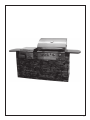
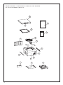
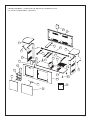
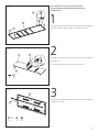
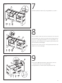
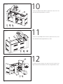
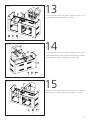
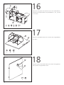
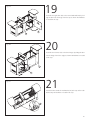
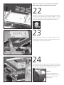
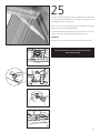
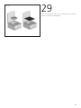
SERIAL #:
Before assembling please note:
Natural gas conversion kit is available
at Canadian Tire #85-1621-4
Entertainment Island 6000 SI Barbecue
S A F E U S E , C A R E A N D A S S E M B LY M A N U A L
DANGER
If You Smell Gas
1. Shut off gas to the appliance.
2. Extinguish any open flame.
3. Open lid.
4. If odor continues, keep away from the
appliance and immediately call your
gas supplier or your fire department.
WARNING
1. Do not store or use gasoline or other
flammable liquids or vapors in the
vicinity of this or any other appliance.
2. An LP cylinder not connected for use
shall not be stored in the vicinity of
this or any other appliance.
WARNING
Failure to follow all of the manufacturer’s
instructions could result in hazardous
fires, explosions, property damage,
or serious personal injury or even death.
HEAVY ARTICLE NEEDS 2 TO LIFT
5 YEAR LIMITED WARRANTY
8 5 - 1 6 2 0 - 6 P R O PA N E ( G 6 1 5 0 1 )
Read and save this manual for future reference.
If pre-assembled, leave this manual with
WARNING
Follow all leak check procedures carefully
prior to operation of barbecue,
even if barbecue was store assembled.
Do not try to light this barbecue
without reading the Lighting Instructions
section of this manual.
unit for consumer’s future reference.
Centro Customer Care Hotline
1-877-707-5463
THIS BARBECUE IS FOR
O U T D O O R U S E O N LY
TA B L E O F C O N T E N T S
WARRANTY
Warranty . . . . . . . . . . . . . . . . . ii
5 Year Limited Warranty
Installation Information . . . . . . 1
Additional Warnings . . . . . . . . 1
This Centro BBQ carries a five year limited warranty against defects in manufacturing workmanship. This Limited Warranty is nontransferable and becomes void if used for commercial
or rental purposes. This warranty applies only when grill is used in Canada. The bill of sale
or a copy will be required together with the serial number and model number when making
Use of LP Gas Cylinder, . . . . .1-2
any warranty claims from Trileaf Distribution. Trileaf Distribution reserves the right to have
Transportation and
its representatives inspect any product or part prior to honouring any warranty claim. Trileaf
Storage of the LP Cylinder,
Distribution shall not be liable for any transportation charges, shipping and handling charg-
Filling the LP Cylinder
es, or labour cost. This warranty is for replacement of defective parts only. The Manufacturer
Prior to Using the Grill . . . . . . . 3
will not be responsible for incidental or consequential damages or any labor cost. Inability to
provide proof of purchase, or if warranty coverage has expired, any request for parts will be
Safety Hose and Regulator . . . . 4
subject to parts, shipping and handling fees. This limited warranty does not cover damage
Safety Leak Testing . . . . . . . . . 5
nor does it cover corrosion or discolouration due to misuse, lack of maintenance, grease
due to chipping and scratching of porcelain or painted surfaces including Cooking grates,
Lighting the Grill . . . . . . . . . .6-8
Sear Zone . . . . . . . . . . . . . . . . 9
Operating Instruction
fires, hostile environments, accidents, alterations, abuse or neglect, improper installation
and failure to read and/or abide by any product warnings. This limited warranty does not
cover any damage sustained during removal or storage of this BBQ. Part failure due to lack of
cleaning and maintenance, or use of improper cleaning products such as Oven Cleaner will
not be covered under this manufacturers warranty. This limited warranty does not cover any
Rotisserie Burner . . . . . . . . . . 10
scratches or dents, corrosion or discolouring caused by heat, abrasive or chemical cleaners.
Operating Instructions
Parts installed from other manufactures will nullify this warranty.
Tips On Using . . . . . . . . . . . . 10
5 Year Limited Warranty
Your Rotisserie
The following functional parts are included under this warranty: Burners, manifold assembly and carryover assembly.
Parts List, Parts Diagram, . .12-15
and Hardware Pack for
3 Year Limited Warranty
Centro 6000SI Barbecue and
Multi-purpose Side Burner
The following functional parts are included under this warranty: Burners, manifold assembly and carryover assembly.
Parts List, Parts Diagram, . .16-17
1 Year Limited Warranty
and Hardware Pack
For one year from the date of original retail purchase Trileaf Distributions will replace any
for Entertainment Island
grill part that fails or is found to be defective to the degree of non-performance under
normal household use, during the limited warranty period. Trileaf Distributions ltd. are not
Assembly Instructions . . . . . . 18
responsible for any grill damage sustained during moving, storage, assembling or cleaning.
Unless otherwise noted, as in above limitations, all components are covered for a period of
one year.
IMPORTANT: Should you have difficulty operating this product, or have a part
that has become defective within the stated warranty period, DO NOT RETURN
TO STORE. STORES DO NOT STOCK replacement PARTS AND ARE UNABLE TO HELP
WITH TROUBLESHOOTING ADVICE. PLEASE CALL 1-877-707-5463. Have your Proof of
purchase, serial number and model number available so that the customer support
agent can be of assistance.
Purchaser: By accepting delivery of this Barbecue the purchaser, hereby accepts the foregoing
and expressly waives any other remedy and damages, direct, indirect, and consequential.
Online warranty registration now available. Visit www.centroliving.ca
ii
I N S TA L L AT I O N
I N F O R M AT I O N
The installation of this appliance must be in accordance with all local codes, or in the
absence of local codes:
•
Canadian installation must conform to the current national standards, which at this time
are CAN / CGA-B149.1/2-Natural Gas / Propane installation code.
ADDITIONAL
Minimum clearance to adjacent combustible materials:
WARNINGS
•
76 cm (30˝ ) from furthest protruding edge on side of barbecue.
•
76 cm (30˝ ) from furthest protruding edge on back of barbecue.
See Drawing A
•
Always keep the area around this barbecue clean and clear of any and all combustible
materials such as gasoline or other inflammable liquids, paper or oily rags.
•
Do not operate this barbecue under any overhanging or unprotected construction.
•
Remember this barbecue is for outdoor use only and is not for use on any boat or rec-
•
Use this barbecue outdoors in a well-ventilated area and at least
•
Do not use in garages, or any other enclosed area.
•
Do not leave your barbecue unattended while in operation.
•
Do not obstruct the flow of combustion and ventilation air to the barbecue.
•
Do not use while under the influence of drugs or alcohol.
•
Do not store any spare L.P. (propane) cylinders, full or empty,
Drawing A
•
Do not allow children or pets to play anywhere near the barbecue.
USE OF LP GAS CYLINDER
The self-contained (propane) gas system barbecue is designed to be used with only a 9.1 kg
reational vehicle.
3 m (10’) from any dwelling or other building.
Minimum clearance of 76 cm (30”)
on both sides and back of the barbeque.
under or near your barbecue.
Self-contained
Propane Gas System
(20 lb) propane cylinder equipped with a type-1 cylinder valve. This barbecue cannot be
connected to an existing #510 P.O.L. type valve cylinder (which has left-handed threads).
Do not connect to a propane gas cylinder exceeding 9.1kg capacity or use a cylinder
with any other type of cylinder valve connection device.
The Type-1 valve can easily be recognized by the large external thread on the outside of the
valve. Older existing valves do not have this outer external thread. Any attempt to connect
a regulator to any connector other than the mating Type-1 connector (which comes with a
large, black coupling nut such as the #510 P.O.L.) could result in fires, injuries or property
damage, and could reduce the effectiveness of the important safety features built into
the Type-1 system. Also connecting the #510 P.O.L. fitting to the cylinder will negate the
flow control and the temperature shut-off features built into the new Type-1 connection
system.
•
The cylinder should not exceed 472 mm (18 1/2˝ ) in height and
317 mm (12 1/2˝ ) in diameter.
When purchasing a cylinder for your barbecue, it must be constructed and marked
as meeting the specifications of:
•
Canada: Transport Canada.
1
DANGER
•
NEVER store a spare LP tank under
or near grill or in enclosed areas.
The Cylinder must also be equipped with:
•
A shut-off valve with a correct cylinder valve outlet as specified in current standards.
•
Canada: CAN / CGA 1.6g-M97 Outdoor Gas Grilles.
a) A safety relief valve with direct connection to the vapour space of the cylinder.
b) A collar to protect the tank shut-off valve.
c) A device for vapour withdrawal.
d) A ring on the bottom to secure the tank to its support assembly.
Cylinder Clamp
•
•
Always turn off the cylinder valve completely when the barbecue is not in use.
•
Always handle the tank valve with utmost care.
•
Never connect an unregulated L.P. gas cylinder to the barbecue.
•
Always keep the cylinder, in use, securely fastened in an upright position.
Never fill the cylinder beyond
80% full.
•
An overfilled or improperly stored
WARNING
tank is a hazard due to possible gas
Never store a spare cylinder, empty or full, near or under
release from the safety relief valve.
•
the barbecue when in operation.
If you see, smell or hear escaping
gas, immediately get away
from the LP tank/grill and call your
fire department.
•
If the above is not followed exactly,
a fire causing death or serious injury
•
Never store a spare cylinder, empty or full, near or under the barbecue when in operation.
•
Never expose the cylinders to direct sunlight or excessive heat.
•
Never insert any kind of object into the valve outlet as this may damage the backcheck;
a backcheck that is damaged can leak, and a leaking propane cylinder can result in fires
may occur.
or explosions, property damage, severe injuries or death.
T R A N S P O R TAT I O N
The propane cylinder is totally safe when handled properly, but if misused, the result could
AND STORAGE
be an explosion or fire resulting in serious personal injury and / or property damage.
OF THE LP CYLINDER
To Avoid Unnecessary Risks
•
Always recap the cylinder with the cap provided when not connected to the barbecue.
•
Do not store the cylinder in any enclosed area such as a garage, and make sure the
storage area has lots of ventilation.
•
Do not store the cylinder near any appliances, or in any areas that may become hot,
•
Make sure the cylinder is out of reach of children.
•
When transporting or storing the cylinder, make sure it is in an upright position and
such as the trunk of a vehicle.
not on its side.
•
FILLING THE
LP CYLINDER
Do not smoke around the cylinder, especially when transporting it in a vehicle.
The cylinder must be filled prior to use and must have the air purged. For safety, follow
these instructions when having your cylinder filled:
•
Have only your local qualified LP gas dealer fill or repair a cylinder.
•
Do not overfill the cylinder beyond the safe 80% fill level.
•
Make sure the dealer tests and checks the cylinder for leaks after filling.
WARNING
If the above instructions are not completely adhered to, it could cause
a fire / explosion, resulting in death or serious Injury, or property damage.
2
PRIOR TO USING
Do not use your barbecue until you have carefully read and fully understand all the
information in this manual. Please ensure the following:
•
Your barbecue is properly assembled.
•
There are no leaks in the system (see “Leak Test”).
•
The burner is properly assembled, with the Venturi tubes seated over the valve outlets
(Drawing E) and that there is nothing blocking the Venturi tubes (Drawing F).
•
Ensure that all power cords and / or gas supply hoses will not touch or be
near surfaces that will get hot.
•
Insert valve outlets into Venturi tubes
approximately 6 mm (1/4”)
Drawing E
WARNING
Natural Hazards
Insects and Spiders
The barbecue is in a safe location (see Installation).
Ensure that the valve outlets (orifices) are assembled into the Venturi tubes approximately
6 mm (1/4˝ ) and that the valve outlets and Venturi tubes are approximately parallel to the
bottom of the lower body.
During shipment or storage, it’s possible that small insects like spiders could
find their way into the Venturi tubes and nest or make webs. This could block
the flow of gas through the Venturi tube causing a smoky yellowish flame, or
prevent a burner from lighting. It could even cause the gas to burn outside the
Venturi tube, which could seriously damage your barbecue. If these occur, turn
off the gas flow and wait for the barbecue to cool down. When the barbecue
has cooled, remove the burner and clean out the Venturi tubes with a brush or
pipe cleaner. Replace the burner and ensure that the Venturi tubes are seated
over the orifice located on the gas valves. Cleaning the Venturi tubes should be
conducted periodically, especially at the start of the season.
Note: Damage resulting from blocked Venturi tubes is not covered under
Drawing F
the warranty.
Orifice Size: The orifice, in conjunction with the control valve, acts to regulate and restrict
the amount of gas delivered to the burner. The hole size in the orifice varies by the gas
supply pressure and by the BTU rating of the burner. Grills equipped for LP gas operate at
a much higher gas pressure and therefore have a smaller size orifice.
Hose and Regulator Inspection
Adjustment: The regulator is factory set at a specified outlet pressure of 11” of water column
and is generally factory sealed and not adjustable. Do not try to adjust. The regulator can be
checked by measuring the pressure with a manometer.
Vent Hole: There is a vent hole on top of the regulator. Check that it is clear of dirt and
debris. If the hole is plugged, erratic and dangerous burning may result.
O-ring Seal: Before attaching the regulator to the cylinder, inspect the rubber O-ring on
the P.O.L. fitting. Do not operate the grill if the O-ring is damaged or missing. Seal damage
is common and we recommend replacement of the seal when the burner is replaced or
when the seal is damaged. Cracks, splits or distortion will allow gas to escape. Additionally,
the seal should be soft, pliable, and protrude slightly from the brass P.O.L. valve.
Chew Marks: The hose should be kept clean of grease and food drippings which attract
squirrels and other animals. The animals will often eat the drippings on the hose and chew
into the hose lining trying to get the last taste. Try cleaning the hose with an ammonia
cleaner solution to minimize the attraction.
3
SAFETY HOSE
Propane Gas Models: Your barbecue is designed to operate on L.P. (Propane) gas at a
A N D R E G U L AT O R
pressure of 2.74 Kpa (11˝ water column). A regulator preset to this pressure is supplied with
the barbecue and must be used.
This regulator is equipped with the Type-1 quick-closing connecting system, which incorporates these safety features:
•
Will not allow gas to flow until a positive seal has been made.
•
Has a thermal component that will automatically shut off
•
Has a flow limiting feature, which will restrict the flow of gas
the flow of gas between 115-150ºC (240-300ºF).
to 10 cubic feet / hour.
Should the large, black thermal-sensitive coupling nut be exposed to any extreme temperatures above 115ºC it will soften and allow the regulator probe to disengage from the
valve, and will shut off the gas. Should this occur, do not try to reconnect the nut; instead
replace the whole regulator assembly with a new one (see the attached parts listing for
details). The regulator probe also contains a flow-sensitive feature, which limits the flow of
gas to 10 cubic feet / hour, in the event of a regulator malfunction or hose leak. If the flow
control feature is activated, the cause of this excessive gas flow should be investigated and
corrected before using the barbecue again.
Note: Improperly lighting the barbecue can activate the flow control feature,
resulting in lower heat output. If this occurs, the re-flow feature must be reset by
turning all the burner controls and the cylinder valve off. Wait at least 30 seconds
before slowly turning on the cylinder valve, and then after another 5 seconds turn
the burner valve on and light the barbecue.
•
Never connect this barbecue to an unregulated propane gas supply, or to another kind
•
Visually inspect the whole hose assembly before each use for evidence of wear or
of gas. Do not alter or change the hose or regulator in any way.
damage such as cracks, burns, or cuts. If any damage is found, replace the
assembly before using the barbecue. Use only the recommended replacement hose.
•
To avoid possible damage to the hose, do not allow any grease or other hot materials
to fall on the hose, and make sure the hose does not contact any hot surfaces of
the barbecue.
•
The connection fitting must be protected when it’s disconnected from the cylinder.
Do not allow the fitting to bump or drag on the ground as nicks and scratches could
help create a leak when connecting back to the cylinder.
•
It is important to do the “Leak Test” procedure every time a cylinder is refilled
or any of the components are changed, and especially at the beginning of a
new season.
Natural Gas Conversion Kit is available at Canadian Tire (Part# 85-1621-4)
4
To Reset The Gas Regulator Safety Device
1. Close the LP (propane) tank valve.
2. Turn all burner control knobs to the OFF position.
3. Disconnect the regulator from the LP tank.
4. Open the grill lid.
5. Open all of the control knobs to the high position.
6. Wait 2 minutes.
7. Close all of the control knobs.
8. Re-connect the regulator to the LP tank. Test for leaks.
9. With lid open, push in and turn the CENTER burner control knob to the HIGH
position and then ignite the grill by pressing the Electronic Ignition button.
10. Once lit, close the grill lid.
11. Wait for 10 to 15 minutes for the Barbecue to preheat.
ATTENTION: Proper start up and shut down procedures should be Followed to
avoid regulator safety device activation.
WARNING
If the heat output is too low, the flow control feature may have been
activated by a gas leak. If so, turn off the burner valve and cylinder valve,
and perform the “Leak Test”. If there aren’t any leaks, re-light the burner.
SAFETY
Perform a “Leak Test”
LEAK TESTING
•
Before lighting your barbecue for the first time.
•
Every time the cylinder is refilled, or any component is replaced.
•
At least once every year, preferably at the start of the season.
The “Leak Test” must be done outdoors, away from heat, open flames and flammable liquids.
Do not smoke while performing the test. Use only a mixture of 50/50 liquid soap and water
for leak testing. Never use a match or open flame.
The Following Must Be Checked
•
The tank valve including the threads into the tank (Drawing C).
•
All tank welds (Drawing B).
•
Regulator fittings and tank connections (Drawing C).
•
All hose connections (Drawing D).
•
With a newly filled and tested propane tank attached to the
barbecue and all the barbecue controls turned “OFF”, slowly open
Drawing B
the cylinder valve one full turn.
Drawing C
•
Using a brush and soap, soak all the connections and components
listed above and shown in drawings B, C, D.
•
Look carefully for bubbles forming, which is an indication of leaking gas.
•
Tighten the connections at the bubbled areas until re-testing shows no
•
Shut off the cylinder valve and ensure all control valves are off.
•
Do not use the barbecue if any leaks cannot be stopped. Turn off the
indication of any leaks (shut off cylinder while correcting any leaks).
gas cylinder valve, remove the gas cylinder and seek assistance from
Drawing D
a qualified gas appliance service mechanic or gas dealer.
5
LIGHTING
Make Sure you have followed all the safety checks, procedures and instructions
THE GRILL
indicated in the previous section, before attempting to light the grill.
Lighting The Main Burners
1. Always open the hood completely and always inspect the grill and burners to confirm
that all components are properly positioned before lighting the main burners.
WARNING
Never stand with your head directly over the Barbecue when preparing
to light the main burners, to prevent possible bodily injury.
2. Always confirm that all of the burner control knobs are in the OFF position before
opening the gas supply.
3. Slowly turn on the propane gas supply valve at the tank 1-2 turns.
4. Wait approximately 5 seconds before turning the CENTER burner Control knob to the
HIGH position by pushing down on the knob and turning it counter-clockwise.
This procedure allows pressure to stabilize, and prevents the flow limiting feature
from being activated.
5. Immediately press the Electronic Igniter. You will hear a continuous clicking sound as
the module generates a spark to the burner. The selected burner should light within
5 seconds. Light all remaining burners by pushing in and turning the corresponding
control knob, to the HIGH position. Each burner will automatically ignite.
WARNING
IF THE SELECTED BURNER DOES NOT LIGHT,
immediately turn the burner control knob and cylinder valve to the OFF
position, to prevent gas buildup. Wait five minutes for the gas to
clear and then repeat the preceding starting procedure. IF the burner will
not light when using the Ignitor, follow the match lighting instructions.
6
6. Confirm that the burner is properly lit. If the flame pattern is other than normal,
consult the Troubleshooting Guide for corrective action.
7. Always preheat the Barbecue before starting to cook. Light all burners and adjust
them to the HIGH position for 5-10 minutes. Before placing any food on the Barbecue,
clean the cooking grids with a Porcelain cleaning brush.
8. Adjust the controls to a medium setting for most cooking requirements. A light
coating of cooking oil on the cooking grids, before heating the grill, will prevent
foods from sticking to the grill.
Turning The Burners Off
1. Always turn the burner control knobs to the off position when
cooking has been completed.
2. Promptly turn OFF the gas supply valve at the propane cylinder.
3. Close the hood of the grill.
Match Lighting The Main Burners
1. Open the BBQ lid before manual lighting your BBQ.
2. Confirm that all burner control knobs are in the off position before
opening the Gas supply.
3. Remove cooking grates and remove the flame tamer from the far right
burner (closest to the Sear Zone)
4. Always slowly open the propane tank gas valve approximately 1-2 turns
5. Place an ignited butane lighter or lit match near the burner port holes,
approximately 1.25 cm (1/2”) from the burner.
6. Push in and turn the corresponding main burner control knob to ‘HIGH’. The burner
should light immediately (within four seconds). If it does not turn off the control knob,
extinguish the lighter or match, and wait 5 minutes for gas to clear.
Drawing G
7. Repeat steps. If burner still fails to light, refer to the
Troubleshooting Guide to determine the cause and solution.
8. Once burner is lit, push in and turn all remaining main burner control knobs to HIGH.
The unlit burners will light automatically.
WARNING
Never stand with your head directly over the Barbecue when preparing
to light the main burners, to prevent possible bodily injury.
WARNING
If the heat output is too low, the flow control feature may have
been activated by a gas leak. If so, turn off the burner valve
and cylinder valve, and perform the “Leak Test”. If there aren’t
any leaks, re-light the burner.
7
Lighting the Side Burner
Use the Electronic Igniter on the main control panel and the Side Burner control knob, on
the far left panel, to light the side burner.
•
Push in and turn the side burner control knob to the HIGH position.
•
Push the igniter button.
•
If the burner does not light, turn the control knob to the
•
Repeat the above instructions. If the side burner still does not light,
OFF position and wait 5 minutes for the gas to clear.
refer to the troubleshooting section for help or light the burner manually.
Note: The side burner is designed to accept a maximum weight of 20 lb. Do not overload
the side burner.
Lighting the Side Burner with a Match
•
Place match in front ring of provided match holder.
•
Place a lighted match through the hole to within 16 cm (1/2˝ ) of the side burner.
•
Push in and turn the burner knob to the “HIGH” position. At this point,
the burner should light, if it doesn’t after 5 seconds, turn the
control knob back to the “OFF” position and wait for the gas to clear.
•
Wait 5 minutes, and then repeat the manual lighting procedure. If after three
tries the burner still does not light, review the troubleshooting guide for help.
Visually Check Burner Flame
HIGH
Take off the grates and flame tamers. Light burners. Adjust the flame by turning the knobs
LOW
from “HIGH” to “LOW”. The flames will be smaller when the knobs are in the “LOW” position. Always check flame prior to each use. Perform flame check for side burner.
8
SEAR ZONE
1. Follow all safety check and lighting procedures for lighting main burners.
O P E R AT I N G
2. Turn the infrared burner knob to HIGH position.
INSTRUCTIONS
3. Push the igniter button until a clicking sound is heard to light the infrared burner.
4. There is no low flame adjustment on this burner.
Match Lighting
Follow the match lighting procedure used for the main burners on Page 7 of this manual
to light the Sear Zone.
When the BBQ is not in use, always cover the infrared burner with the Storage
cover provided, to avoid burner damage caused by moisture or harsh weather.
Purchase a Centro BBQ Cover to help protect your grill.
Operating the infrared burner
1. Always keep the BBQ lid OPEN when the infrared burner is in use.
2. Do not use the infrared burner and the rotisserie burner simultaneously.
3. This burner is FOR SEARING ONLY!! Not for cooking!!
4. DO NOT use this burner to cook FATTY MEAT.
Serious grease fire might take place.
5. For steak or pork, sear each side for max 3 minutes to avoid from overcooking.
See the Centro Grilling Guide for further maintenance, operating, troubleshooting, and cooking tips.
Natural Gas Conversion Kit is available at Canadian Tire (Part# 85-1621-4).
9
ROTISSERIE BURNER
•
Turn all knobs to “OFF”
O P E R AT I N G I N S T R U C T I O N S
•
Open lid during lighting. Turn gas on at LP tank.
•
Push in and turn the Rotisserie Burner Knob to the “ON” position.
•
Push the Igniter. Be sure burner lights and stays lit.
•
No temperature adjustment. Only ON and OFF.
•
If the Igniter does not work, follow the match lighting
instructions for the main burner on Page 7 of this manual.
Match Lighting Procedure
•
Open lid prior to lighting.
•
Place an ignited lighter or lit match near the ports,
•
Push in and turn the Rotisserie burner control knob to ‘HIGH’. The burner
approximately 1.25 cm (1/2”) from burner.
should light immediately (within four seconds). If it does not turn off the control
knob, extinguish the lighter or match, and wait 5 minutes for gas to clear.
•
Repeat steps 1 to 4. If burner still fails to light, refer to the
Troubleshooting Guide to determine the cause and solution.
TIPS ON USING
Guide to Rotisserie Cooking
YOUR ROTISSERIE
Rotisserie cooking produces foods that are moist and flavourful. Most commonly used for
cooking meat or poultry, the rotisserie is designed to cook food slowly. You can place a cooking pan beneath the food to collect juices for basting and gravy. To flavour the contents of
the cooking pan you may add herbs, onions, or other spices of your choice.
Balancing the Food
In rotisserie cooking, balancing the food is of utmost importance. The rotisserie must turn
evenly or the stopping and starting action will cause the food to cook unevenly and possibly
burn the heavier side.
The easiest foods to balance are those of uniform shape and texture. To test if the food is
balanced correctly when secured, place the ends of the rotisserie spit loosely in the palms
of your hands. If there is no tendency to roll, give the spit a quarter turn. If it is still stable,
give it a final quarter turn. It should rest without turning in each of these positions. It can
then be attached to your grill.
Food Preparation
When preparing poultry, truss the birds tightly so that wings and drumsticks are close to
the body of the bird. The cavity of bird may be stuffed prior to this. Pull the neck skin down
and, using a small skewer, fix it to the back of the bird. Push the rotisserie spit through
lengthwise, catching bird in the fork of the wishbone. Centre the bird and tighten with the
holding forks. Test the balance as described before.
A rolled piece of meat requires the rotisserie skewer to be inserted through the centre of
the length of meat, then secured and balanced.
For meats that contain bones, it is best to secure the rotisserie skewer diagonally through the
meaty section. If protruding bones or wings brown too quickly, cover with pieces of foil.
10
11
PA R T S L I S T I N G F O R C E N T R O 6 0 0 0 S I B B Q A N D M U LT I - P U R P O S E S I D E B U R N E R
8 5 - 1 6 2 0 - 6 P R O PA N E ( G 6 1 5 0 1 )
Item No.
Quantity
Specification
A
1
Top Lid Assembly
Part No.
Item No.
Quantity
Specification
CA
1
Manifold Assembly (w/ main & rotisserie valve) G615-4800-01
Part No.
AA
1
Top Lid Weldment
G615-0100-01
CB
1
Regulator
AB
1
Top Lid Handle
G607-0001-01
CC
1
PVC Hose A, Sideburner
G615-0005-01
AC
1
Thermometer
G413-0029-01
CD
1
PVC Hose B, Sideburner
G615-0007-01
AD
2
Screw for Top Lid
G607-0002-01
G615-0006-01
B
1
Burner Box Assembly
G602-0050-01
CE
1
Sideburner Valve
CF
1
Rotisserie Flexible Hose w/ Nozzle
G615-0021-01
CG
1
Electronic Ignition Kit
G502-0066-02
BA
1
Burner Box Weldment
G610-0200-01
CH
1
Electrode w/ Wire f/ Main Burner
G607-0008-01
BB
1
Heat Shield A
G615-0020-01
CI
1
Control Panel
G610-0054-01
BC
1
Left Side Upper Panel
G615-0200-01
CJ
6
Control Knob Bezel
G419-0006-01
BD
1
Right Side Upper Panel
G615-0300-01
CK
5
Control Knob
G610-0015-01
BE
1
Rotisserie Burner
G610-6000-01
CL
1
Control Knob, Sear Zone
G610-8300-01
BF
1
Backburner Brace B
G610-0017-01
CM
1
Left Rail, Grease Tray
G615-0009-01
BG
1
Wind Shield, Rotisserie
G502-0095-01
CN
1
Right Rail, Grease Tray
G615-0010-01
BH
1
Burner Brace
G607-0006-02
CO
1
Upper Rear Panel
G615-0008-01
BI
2
Main Burner - A
G502-1700-01
CP
1
Grease Tray
G610-6400-01
BJ
1
Main Burner - B
G502-1900-01
CQ
1
Heat Shield, Tank
G615-0011-01
BK
1
Sear Zone Burner
G610-5000-01
CR
1
Front Brace
G615-5000-01
BL
3
Flame Tamer
G607-0005-01
CS
1
Electronic Ignition Button
G409-0030-01
BM
1
Infrared Burner Rain Shield
G610-0013-01
Side Burner Shelf Assembly
BN
2
Cooking Grate - A, Burnerbox
G610-0002-01
D
1
BO
1
Cooking Grate - B, Burnerbox
G610-0003-01
DA
1
Sideburner Lid
BP
1
Warming Rack
G610-0001-01
DB
2
Sideburner Lid Handle
G607-0040-01
DC
1
Sideburner Griddle
G615-0018-01
G615-0500-01
BQ
4
Upper Brace
G615-0013-01
BR
1
Match Holder
G608-0019-01
DD
1
Sideburner Grate
G615-0017-01
BS
1
Rotary Ignition Kit
G105-0018-01
DE
1
Sideburner Rear Panel
G615-0014-01
DF
1
Sideburner Kit
G615-0600-01
DG
1
Electrode w/ Wire f/ Sideburner
G105-0012-01
DH
1
Sideburner Hosing
G615-6100-01
12
DI
1
Condiment Basket
G615-0016-01
DJ
1
Sideburner Bracket
G615-0015-01
DK
1
Pull Out Tank Tray
G615-8000-01
DL
1
Instruction Manual
G615-M001-01
DM
1
Hardware Pack
G615-B001-01
E N T E R TA I N M E N T I S L A N D C E N T R O 6 0 0 0 S I B A R B E C U E
8 5 - 1 6 2 0 - 6 P R O PA N E ( G 6 1 5 0 1 )
AC
BO
BN
AA
AD
AD
BL
BP
BM
AB
BG
BK
BI
BQ
BQ
BJ
BF
BH
BD
BE
BC
BA
CI
CF
BB
CJ
BR
CD
CC
CA
CE
CK
CB
CL
CH
CS
CG
CR
CQ
CN
CM
CO
CP
13
E N T E R TA I N M E N T I S L A N D M U LT I P U R P O S E S I D E B U R N E R
8 5 - 1 6 2 0 - 6 P R O PA N E ( G 6 1 5 0 1 )
DA
Manual
DL
DB
DC
Hardware
Pack
DD
DE
DF
DG
BQ
CK
BQ
DH
DI
14
DJ
BS
DK
DM
C E N T O 6 0 0 0 S I B B Q A N D M U LT I - P U R P O S E S I D E B U R N E R
A S S E M B LY I N S T R U C T I O N S
No.
Description
Quantity
1
1/4-20UNC x 13 Screw
6
2
ø7 Lock Washer
6
Pliers
3
ø7 Washer
6
Rubber mallet
4
1/4-20UNC x 35 Wing Screw
4
5
AA Battery
1
Tools Needed for Assembly
•
1/4” and 5/16”
crossed screwdriver
•
•
•
Hardware Pack List
Adjustable wrench
Before assembling the barbecue, read these instructions carefully.
Assemble the barbecue on a flat, clean surface. Grill is heavy. You
should have two people assemble the barbecue together.
Notes: Do not fully tighten all the nuts during this initial stage.
Caution: Sheet metal can cause injury. Wear gloves when
installing the grill. Use care when assembling.
Before assembling please note:
Natural Gas Conversion Kit is available at Canadian
Tire (Part# 85-1621-4).
15
PA R T S L I S T I N G F O R
E N T E R TA I N M E N T
Item No.
Quantity
Specification
Part No.
EA
1
Top Rear Granite Support Brace
G615-0061-01
G615-0055-01
EB
1
Rear Island Wall
ISLAND AND GRANITE
EC
1
Center Granite Countertop
G615-0064-01
COUNTER TOP
ED
1
Top Support Bar
G615-0056-01
8 5 - 1 6 2 0 - 6 ( P R O PA N E )
(G61501)
16
EE
2
Granite Side Shelf
G615-0065-01
EF
4
BBQ & Sideburner Support Bars
G615-0059-01
EG
1
Wire Brace
G615-0052-01
EH
1
Tank Exclusion, Wire Frame
G615-0060-01
EI
1
Right Island Wall
G615-0054-01
EJ
2
Shelf Support Bracket
G615-0066-01
G615-0051-01
EK
4
Bottom Support Feet
EL
1
Bottom Panel
G615-0050-01
EM
1
Front Island Wall
G615-9100-01
EN
1
Right Door
G615-0070-01
EO
1
Paper Towel Holder
G615-0071-01
EP
1
Left Door
G615-0067-01
EQ
1
Trash Basket
G615-0068-01
G615-0069-01
ER
1
Wire Handle for Trash Basket
ES
1
Top Front Granite Support Brace
G615-0062-01
ET
1
Left Island Wall
G615-0053-01
EU
1
Support Bracket
G615-0063-01
EV
1
Hardware Pack - Entertainment Island
G615-B001-02
E N T E R TA I N M E N T I S L A N D W I T H G R A N I T E C O U N T E R T O P
8 5 - 1 6 2 0 - 6 ( P R O PA N E ) ( G 6 1 5 0 1 )
EA
EB
EE
EC
ED
EJ
EE
EF
EF
ET
ES
EU
EK
EG
EH
EK
ER
EI
EJ
EQ
EL
EP
EK
EM
EO
Hardware
Pack
EV
EN
17
E N T E R TA I N M E N T I S L A N D A N D G R A N I T E C O U N T E R T O P
A S S E M B LY I N S T R U C T I O N S
Hardware Pack List
No.
Description
Quantity
A
5/16-18UNC x 38 Screw
2
B
5/16-18UNC x 20 Screw
10
Pliers
C
5/16-18UNC Nut
26
Rubber mallet
D
ø8 Washer
38
E
ø8 Lock Washer
38
F
1/4-20UNC x 15 Screw
13
G
ø6 Washer
13
H
ø6 Lock Washer
13
Assemble the barbecue on a flat, clean surface. Grill is heavy. You
I
No. 8-32UNC x 10 Screw
10
should have two people assemble the barbecue together.
J
ø4 Washer
10
Tools Needed for Assembly
•
1/4” and 5/16”
•
crossed screwdriver
•
•
Adjustable wrench
Before assembling the barbecue, read these instructions carefully.
Notes: Do not fully tighten all the nuts during this initial stage.
Caution: Sheet metal can cause injury. Wear gloves when
installing the grill. Use care when assembling.
Before assembling please note:
Natural Gas Conversion Kit is available at Canadian
Tire (Part# 85-1621-4).
18
Key A: 5/16-18UNC x 38 Screw (2)
Key B: 5/16-18UNC x 20 Screw (10)
Key C: 5/16-18UNC Nut (26)
Key D: ø8 Washer (38)
Key E: ø8 Lock Washer (38)
Key F: 1/4-20UNC x 15 Screw (13)
Key G: ø6 Washer (13)
Key H: ø6 Lock Washer (13)
Key I: No. 8-32UNC x 10 Screw (10)
Key J: ø4 Washer (10)
Note: Hardware for Steps #1-21 are provided in
Fig. 1
the Entertainment Island with Granite Countertop
EK
EL
hardware pack.
1
Assemble the Bottom Support feet (EK) (x4) and Nut (x4) to the Bottom
EK
Panel (EL) as shown. Tighten all bolts. Turn Bottom Panel over.
Fig. 2
EL
EG
2
Assemble the Wire Brace (EG) to the Bottom Panel (EL) using hard-
ware parts I & J.
Put the Bottom Panel assembly (EL) aside until Step 6.
EK
Fig. 3
EB
3
Assemble the Top Support Bar (ED) to the Rear Island Wall (EB) using
ED
hardware A, D, and E.
19
Fig. 4
ED
ET
ED
4
Align and connect the Left (ET) and Right (EI) Island Walls to the Top
Support Bar (Ed) using Hardware C, D, and E as shown.
EI
Fig. 5
5
ET
Align and connect the Front Island Wall (EM) to the Left and Right
Island Walls (ET + EI) using Hardware B, C, D, E as shown.
EI
EM
Fig. 6
EL
Insert
EI
EB
6
Invert the entire Entertainment Island Cart in this step to assemble
the Bottom Panel (EL). At least two people are recommended
for this and all assembly steps. Align the Bottom Panel (EL) to
the bottom of the Entertainment Island Cart.
Note: Bottom Panel air vents should be on the right side of the
Island Cart.
ET
EM
20
7
Fig. 7
EL
Assemble the Bottom Panel (EL) by using Hardware F, G, and H.
EM
8
Fig. 8
EI
EB
Once the Bottom Panel (EL) has been attached to the Front and
EL
Rear Island Walls (EM + EB), you can now attach the Bottom Panel
(EL) to the Left and Right Island Wall (ET + EI) using Hardware C, D,
and E. Once all assembly has been completed, you can now turn
the Entertainment Island upright.
ET
Attention: Please ensure the unit is well supported from both sides
and the centre to avoid damage.
EM
9
Fig. 9
EF
A. Position the BBQ and Side Burner support bar (EF) into the
EF
Island as shown. (rear-view assembly image).
B. Using hardware F, G and H attach the bottom panel (EL).
B
EL
EB
21
10
Fig. 10
EF
Connect the BBQ and Side Burner support bars (EF) to the rear
EB
island wall (EB) using hardware D, E and B.
11
Fig. 11
EF
Connect the front BBQ and side burner support bars (EF) to the
EM
front Island wall (EM) using hardware D, E and C.
Fig. 12
EI
12
Assemble the Tank Exclusion wire frame (EH) to the inside of the
Right Island Wall (EI) and Bottom panel (EL) using hardware I and J.
EL
22
EH
Fig. 13
EA
EB
EA
EB
13
Insert and Attach the Top rear granite support brace (EA) to the
Rear Island Wall (EB) using hardware C, D and E.
14
Fig. 14
ES
ES
Insert and attach the Top Front Granite Support brace (ES) to the
Front Island Wall (EM), together with the Support Bracket, as shown
EM
using hardware F, G and H. (Image shown is a rear view).
EA
15
Fig. 15
EC
EA
Mount the Center Granite counter top (EC) to the Top Front and Rear
Support braces (ES + EA), as shown using hardware H, G, and F.
ES
23
Fig. 16
16
EE
Mount the Left granite Side Shelf (EE) to the Left Island Wall (ET)
using the Shelf Support Bracket (EJ) and hardware C, D, E, F, G and
H, as shown.
EJ
EM
Fig. 17
EQ
EP
17
Attach the Trash Basket (EQ) to the Left Door (EP) using hardware
D, E and C.
Fig. 18
EO
18
Attach the paper Towel Holder (EO) to the inside of the Right Door
EN
24
(EN) as shown, using hardware I and J.
19
Fig. 19
Assemble the right door (EN) to the Front Island Wall (EM) by slid-
ing the door into the hinges from the top as shown. No hardware
is needed in this step.
Turn
EN
EM
20
Fig. 20
Assemble the Left Door (EP) to the lower hinges by sliding the door
into the hinges from left to right, as shown. No hardware is needed
in this step.
Turn
EM
EP
Insert
21
Fig. 21
Attach the Wire Handle for Trash Basket (ER) to the top of the Trash
Basket (EQ). No hardware is needed in this step.
ER
EQ
25
Fig. 22
Hardware for Steps 22-24 are provided in Centro 6000 SI
BBQ and Multi-purpose Side Burner hardware pack.
22
Assemble the 2 tracks of Pull-out Tank Tray (DK) to the bottom panel
(located inside the right door) by using 1/4”-20UNC x 13 screw
(x6), 7mm flat washer (x6), and 7mm lock washer (x6), as shown.
Then insert the body of the Pull-out Tank Tray into the tracks.
Fig. 23
23
Place the main grill head onto the 2 BBQ Support bars of the
Entertainment Island on the right. Secure the grill head to the 2
supporting bars by 2 wing screws as shown.
Fig. 24
24
Place the Multi-purpose Side Burner onto the 2 Side Burner Supporting
bars at the left side of the Entertainment Island. Secure the side
burner to the 2 supporting bars by 2 wing screws as shown.
Important
Insert the Side Burner from
back. Be careful the interference
between the PVC hose (CD)
and stone base.
26
25
Fig. 25
Connect the female and male ends of the QDD device found under
the main grill head and Side Burner. Follow by connecting the Hose
and Regulator to the Propane tank.
Make sure the hose and regulator will pass through the front gap
between the front panels and grill body.
Secure 20lb propane tank onto the bottom shelf base of the cart as
shown. Attach the regulator valve to 20lb propane tank.
WARNING
Do not store an extra tank inside the Entertainment Island Cart.
Natural Gas Conversion Kit is available at Canadian
Tire (Part# 85-1621-4).
Tank Holder
Cylinder Clamp
27
Fig. 26
26
Open lid and position the 3 Flame Tamers (BL) above the 3 Main
Burners (BI&BJ). Place the 2 cooking grate (BN) into the burner box
to the left as shown. Place the “SEARZONE” cooking grate (BO)
above the Sear Zone (BK).
Remember to cover the Sear Zone Burner with cover (BM)
when not in use to avoid burner damage caused by damp
conditions, rain or snow.
Fig. 27
27
Attach the Warming Rack (BP) to the Back Burner Brace (BF) as
shown. Make sure to insert the front 3 bars into the 3 holes of the
Back Burner Brace (BF). Place the two legs of the Warming Rack clip
onto the edge of Burner Box Weldment (BA).
Fig. 28
28
Unscrew the Igniter Cap and place AA battery which is provided
into Igniter (CG) with positive end (+) facing outward. Screw Igniter
Cap onto igniter as shown.
28
Fig. 29
29
Place the Side Burner Grate (DD) or Griddle (DC) onto the Side
Burner for different cooking purpose.
29
DISTRIBUTOR
Trileaf Distribution Trifeuil
Toronto, Canada
M4S 2B8


![[CEN 067] Conversion Kit E.indd](http://vs1.manualzilla.com/store/data/007377917_1-c772fcf018dd9c891b42f5e0f5f673fc-150x150.png)


![[WPE 039] E20101 BBQ Manual E 12/22/04 2:05 AM](http://vs1.manualzilla.com/store/data/007299302_1-29c468208e73d97f1377c17012db49e6-150x150.png)