1
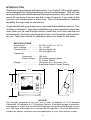
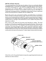
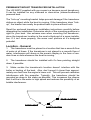
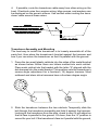
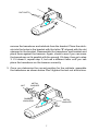
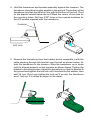
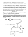
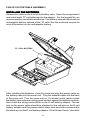
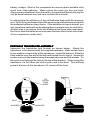
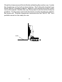
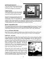
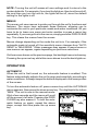
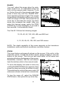
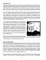
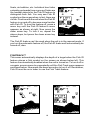
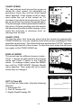
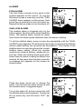
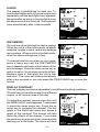
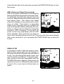
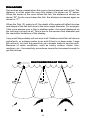
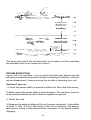
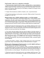
Fish ID 128
Fish ID 128
INST
ALLA
TION AND OPERA
TION
INSTALLA
ALLATION
OPERATION
INSTR
UCTIONS
INSTRUCTIONS
®
1
TABLE OF CONTENTS
INTRODUCTION .............................................................................................. 3
SPECIFICATIONS ........................................................................................... 3
INSTALLATION ............................................................................................... 4
PERMANENT MOUNT TRANSDUCER .......................................................... 5
POWER CONNECTIONS ............................................................................... 10
FISH ID 128 PORTABLE ................................................................................ 11
KEYBOARD BASICS ...................................................................................... 14
DISPLAY ......................................................................................................... 14
OPERATION ................................................................................................... 15
MENUS ........................................................................................................... 15
AUTOMATIC ................................................................................................... 15
RANGE ........................................................................................................... 15
ZOOM ............................................................................................................. 16
SENSITIVITY .................................................................................................. 17
FISH ID ........................................................................................................... 17
FISH TRACK™ ............................................................................................... 18
CHART SPEED .............................................................................................. 19
DISPLAY MODE ............................................................................................. 19
ALARMS ......................................................................................................... 20
BACK LIGHT ................................................................................................... 21
FEET/METER ................................................................................................. 21
DISPLAY CONTRAST .................................................................................... 21
ASP (Advanced Signal Processing) ............................................................... 22
SIMULATOR ................................................................................................... 22
FISH ARCHES ................................................................................................ 23
WATER TEMPERATURE AND THERMOCLINES ......................................... 24
TROUBLESHOOTING .................................................................................... 25
WARRANTY ................................................................................................... 29
Copyright © 1998, Eagle Electronics
All features and specifications in this manual are subject to change
without notice.
All screens in this manual are simulated.
Eagle Electronics
PO Box 669
Catoosa, OK 74015
2
INTRODUCTION
Thank you for purchasing an Eagle sonar. Your Fish ID 128 is a high quality
sonar designed for both professional and novice fishermen. This unit has
an automatic feature that finds and displays the bottom, fish, structure, and
more! All you have to do is press the on key. However, if you wish to fine
tune the unit, simply press a menu key. This unit has powerful features
available through easy-to-use menus.
To get started with your Eagle sonar, first read the installation section. This
is where it all begins. Improper installation can cause problems down the
road. After you’ve read the instructions, install the unit, then read the rest
of the manual. The more you know about your unit, the better it will perform
for you. Take this manual for reference when you head for the water.
SPECIFICATIONS
Dimensions ......................
Input Voltage ....................
Current Drain ...................
...........................
Transmitter
Frequency ..........
Output Power .....
...........................
Display ...........................
...........................
5.9" W x 5.35" H x 3.4" D
10 - 15 vDC
150 ma (lights off)
250 ma (lights on)
192 kHz
275 watts (peak-to-peak)
37.5 watts (RMS)
128 pixels (H) x 64 pixels (W)
Supertwist Liquid Crystal Display
3.4"
5.35"
5.9"
NOTICE!
The storage temperature for your unit is from -4 degrees to +167 degrees
Fahrenheit (-20 degrees to +75 degrees Celcius). Extended storage in temperatures higher or lower than specified will damage the liquid crystal display in your
unit. This type of damage is not covered by the warranty. For more information,
contact the factory customer service department or your local service center.
3
INSTALLATION - Bracket
You can install the unit on the top of a dash or from an overhead with the
supplied bracket. It can also be installed in the dash with an optional IDA3 or IDA-4 mounting kit. If you use the supplied bracket, you may be
interested in the optional GBSA-1 swivel bracket kit. This converts the
gimbal bracket to a swivel mount which can be used on the dash or
overhead mounting positions. Installation instructions for the in-dash and
swivel mounting kits are supplied with the adapter kits.
Mount the unit in any convenient location, provided there is clearance
when it’s tilted for the best viewing angle. Holes in the bracket’s base allow
wood screw or through bolt mounting. It may be necessary to place a piece
of plywood on the back side of thin panels to reinforce the panel. Make
certain there is enough room behind the unit to attach the power and
transducer cables.
Drill a hole in the dash for the power and transducer cables. The best
location for this hole is immediately under the gimbal bracket. This way, the
bracket covers the hole. The smallest hole the power/transducer cable
connector can pass through is 5/8". Note: Install the transducer before
wiring the power cable!.After installing the transducer and power cables,
slide the bracket over the hole, then route the transducer and power cables
out the slot in the back of the bracket. Finally, fasten the bracket to the dash.
FISH ID 128
GIMBAL BRACKET
RUBBER WASHER
PLASTIC WASHER
(PORTABLE UNITS ONLY)
GIMBAL KNOB
Attach the unit to the gimbal bracket using the supplied gimbal knobs and
washers as shown above.
4
PERMANENT MOUNT TRANSDUCER INSTALLATION
The HS-WSPC supplied with your sonar is a transom mount transducer.
It can be installed on any outboard or stern-drive (inboard\outboard)
powered boat.
The “kick-up” mounting bracket helps prevent damage if the transducer
strikes an object while the boat is moving. If the transducer does “kickup”, the bracket can easily be pushed back in place without tools.
Read the enclosed transducer installation instructions carefully before
attempting the installation. Determine which of the mounting positions is
right for your boat. Use extreme care when mounting the transducer,
since the transducer location is the most critical part of a sonar installation. If it isn’t done properly, the sonar can’t perform at it’s designed
potential.
Location - General
1. The transducer must be placed in a location that has a smooth flow
of water at all times. If the transducer is not placed in a smooth flow of
water, interference will show on the sonar’s display in the form of random lines or dots whenever the boat is moving.
2. The transducer should be installed with it’s face pointing straight
down, if possible.
3. Make certain the transducer's location doesn’t interfere with the
trailer or hauling of the boat. Also, don’t mount it closer than approximately one foot from the engine’s lower unit. This will prevent cavitation
interference with the propeller. Typically, the transducer should be
mounted as deep in the water as possible. This increases the chance
that it will be in the water in high speed and reduces the possiblity of air
bubble interference.
POOR LOCATION
POOR ANGLE
GOOD LOCATION
5
4. If possible, route the transducer cable away from other wiring on the
boat. Electrical noise from engine wiring, bilge pumps, and areators can
be displayed on the sonar’s screen. Use caution when routing the transducer cable around these wires.
CAUTION!
CLAMP THE TRANSDUCER CABLE TO
TRANSOM NEAR THE TRANSDUCER. THIS
WILL HELP PREVENT THE TRANSDUCER
FROM ENTERING THE BOAT IF IT IS
KNOCKED OFF AT HIGH SPEED.
GOOD LOCATION
Transducer Assembly and Mounting
The best way to install this transducer is to loosely assemble all of the
parts first, then place the transducer’s bracket against the transom and
see if you can move the transducer so that it’s parallel with the ground.
1. Press the two small plastic ratchets into the sides of the metal bracket
as shown below. Notice there are letters molded into each ratchet.
Place each ratchet into the bracket with the letter “A” aligned with the
dot stamped into the metal bracket. This position sets the transducer’s
coarse angle adjustment for a fourteen (14) degree transom. Most
outboard and stern-drive transoms have a fourteen degree angle.
DOT
2. Slide the transducer between the two ratchets. Temporally slide the
bolt though the transducer assembly and hold it against the transom.
Looking at the transducer from the side, check to see if it will adjust so
that its face is parallel to the ground. If it does, then the “A” position is
correct for your hull. If the transducer’s face isn’t parallel with the ground,
6
RATCHETS
remove the transducer and ratchets from the bracket. Place the ratchets into the holes in the bracket with the letter “B” aligned with the dot
stamped in the bracket. Reassemble the transducer and bracket and
place them against the transom. Again, check to see if you can move
the transducer so it’s parallel with the ground. If it does, then go to step
3. If it doesn’t, repeat step 2, but use a different letter until you can
place the transducer on the transom correctly.
3. Once you determine the correct position for the ratchets, assemble
the transducer as shown below. Don't tighten the lock nut at this time.
NUT
METAL
WASHER
RUBBER
WASHERS
METAL
WASHER
BOLT
7
4. Hold the transducer and bracket assembly against the transom. The
transducer should be roughly parallel to the ground. The bottom of the
transducer bracket should be in line with the bottom of the hull. Don't
let the bracket extend below the hull! Mark the center of the slots for
the mounting holes. Drill two 5/32" holes in the marked locations for
the #10 screws supplied with the transducer.
TRANSOM
SIDE VIEW
5. Remove the transducer from the bracket and re-assemble it with the
cable passing through the bracket over the bolt as shown below. Attach the transducer to the transom. Slide the transducer up or down
until it’s aligned properly on the transom as shown below. Tighten the
bracket’s mounting screws. Adjust the transducer so that it’s parallel to
the ground and tighten the lock nut until it touches the flat washer, then
add 1/4 turn. Don’t over tighten the lock nut! If you do, the transducer
won’t “kick-up” if it strikes an object in the water.
8
6. Route the transducer cable to the sonar unit. Make certain to leave
some slack in the cable at the transducer as shown at the bottom of
the previous page. If possible, route the transducer cable away from
other wiring on the boat. Electrical noise from the engine’s wiring, bilge
pumps, VHF radio wires and cables can be picked up by the sonar.
IMPORTANT!
Clamp the transducer cable to the transom close to the transducer. This
can prevent the transducer from entering the boat if it is knocked off at
high speed.
7. Make a test run to determine the results. If the bottom is lost at high
speed, or if noise appears on the display, try sliding the transducer
bracket down. This puts the transducer deeper into the water, hopefully below the turbulence causing the noise. Don't allow the transducer bracket to go below the bottom of the hull!
Fish Arches
If you do not get good fish arches on your display, it could be the
transducer is not parallel with the ground when the boat is at rest in the
water, or at slow trolling speeds. If the arch slopes up, but not back
down, then the front of the transducer is too high and needs to be
lowered. If only the back half the the arch is printed, then the nose of the
transducer is angled too far down and needs to be raised.
TRANSDUCER AIMED TOO FAR
BACK
TRANSDUCER AIMED TOO
FAR FORWARD
PROPER TRANSDUCER ANGLE
9
POWER CONNECTIONS -PERMANENT MOUNT UNITS ONLY
IMPORTANT! INSTALL THE TRANSDUCER BEFORE WIRING THE POWER CABLE!
The Fish ID 128 works from a 12 volt DC system only. For the best results,
run the power cable directly to the boat’s battery. Keep the power cable
away from other boat wiring, especially the engine’s wires. This will give the
best isolation from electrical noise. If the supplied cable is not long enough
to reach the battery, splice #18 gauge insulated wire to it. If you do extend
the power cable, make certain to attach the in-line fuse holder supplied with
the unit to the battery or power source. This will protect both the unit and
the power cable in the event of a short. Use only a 3-amp fuse.
IMPORTANT!
Do not use this product without a 3-amp fuse wired into the power cable!
Failure to use a 3-amp fuse will void your warranty!
You can also attach the power cable to an accessory or power buss,
however, you may have problems with electrical interference. This unit has
reverse polarity protection. No damage will occur if the power wires are
reversed. However, the unit will not work until the wires are attached
correctly.
TO
SONAR
UNIT
TO
TRANSDUCER
BLACK
WIRE
RED
WIRE
3 amp
FUSE
12 VOLT
BATTERY
10
FISH ID 128 PORTABLE ASSEMBLY
INSTALLING THE BATTERIES
Release the latch on the front of the battery case. Open the compartment
and install eight "D" cell batteries into the adapter. For the longest life, we
recommend you use alkaline batteries. This battery case will also hold one
rechargable battery instead of the "D" cells. See the enclosed coupon for
more information on the rechargable battery.
"D" CELL BATTERY
After installing the batteries, close the case and plug the power cable on
the battery case into the sonar unit. Plug the adapter cable into the back
of the sonar unit. Turn the sonar unit on. If it doesn't work, make certain
the battery terminals are making good contact against the battery contacts.
Also check the wiring connections on the D-cell battery adapter. The red
wire on the power cable should be attached to the red wire on the D-cell
battery adapter and the power cable's black wire should be connected to
the black wire on the D-cell battery adapter. If it still doesn't work, check the
11
battery voltage. Most of the complaints we receive about portable units
result from stale batteries. Make certain the ones you buy are fresh.
Always remove batteries from the battery compartment before storing the
unit as dead batteries can leak and corrode the contacts.
In cold weather the efficiency of dry cell batteries drops with the temperature. We find it a good idea to have the sonar unit good and warm along with
the batteries before we leave home. If the batteries do lose a charge, you
can sometimes restore them by placing them in a warm room or car interior.
A better way is to replace them with batteries that have been kept warm.
Don't ever heat the batteries over an open flame or direct hot air onto them.
A fire or explosion could result.
PORTABLE TRANSDUCER ASSEMBLY
Assemble the transducer and bracket as shown below. Attach the
transducer to the bracket with the supplied hardware. Make certain there
is one washer on each side of the transducer, inside the bracket. Slide the
other washer over the end of the bolt and thread the nut onto it. Screw the
suction cup onto the bracket using the supplied screw and flat washer. Tie
the nylon cord through the hole in the top of the bracket. When using this
transducer, tie the other end of the nylon cord to the boat. This will help
prevent the loss of the transducer if it comes off the boat.
TIE
NYLON
CORD
HERE
SCREW
BOLT
WASHER
NUT
WASHER
12
Clean the chosen area of the hull before attaching the suction cup. Locate
the transducer on the hull as shown below. Don't allow the bracket to go
below the hull, as water pressure against it can cause the suction cup to
come off at speed. Moisten the cup, then press it onto the hull as firmly as
possible. Tie the nylon cord to the boat and route the transducer cable to
the sonar unit. Plug the transducer connector into the Fish ID 128. Your
portable sonar is now ready for use.
HULL
13
KEYBOARD BASICS
The unit sounds a tone when you
press any key. This tells you the
unit has accepted a command.
PWR/CLEAR
Use this key to turn the unit on and
off. It also clears menu selections
and the menus from the screen.
Fish ID 128
Note! To turn the unit off, press and
HOLD the PWR/CLEAR down. A
countdown from 3 seconds appears on the screen when you hold the PWR key down for more than a
couple of seconds. When the countdown reaches zero, the unit shuts off.
This prevents you from accidentally turning the unit off.
MENU FWD/MENU REV
This sonar has many features that are accessed with these keys. To scroll
forward through the menus, press the MENU FWD key repeatedly. To go
backwards through the menus, press the MENU REV key repeatedly.
UP and DOWN ARROWS
Use these keys to adjust virtually every feature and function on the unit.
The up arrow key also stops the chart when no menus are displayed.
DISPLAY - General
The lights flash for about ten seconds when the unit is turned on. Two
menus appear, one after the other. The menus are the lights (BACK
LIGHT) and feet-meter selection (FEET/METER). To turn the lights on,
press the up arrow key while the backlight menu is showing. To switch from
feet to meters, press the down arrow key
when the proper menu appears. The menus
disappear after a few seconds. If you don’t
want to wait, press the PWR/CLEAR key to
clear the menus from the screen.
When the unit is first turned on, the display
appears similar to the one at right. The unit is
in the automatic mode. The depth range
displays on the upper left side of the screen.
In the example at right, the range is from 0 to
60 feet and the bottom depth is 48.6 feet.
14
NOTE: Turning the unit off erases all user settings and it returns to the
system defaults. For example, if you turn the lights on, then turn the unit off,
the next time you turn the unit on, the lights will be off, since the default
setting for the lights is off.
MENUS
This sonar unit uses menus to guide you through the unit’s functions and
features. The menu keys accesses these features, allowing you to
customize the unit to your particular needs and water conditions. All you
have to do to leave one menu and enter another is press a menu key
repeatedly. If you ever get lost in the menus, simply press the PWR/CLEAR
key. This clears the menus from the screen.
Menus change depending on the mode the unit is in. For example, if the
automatic mode is turned off, the sensitivity menu changes from “AUTO
SENS” to “MAN SENS.” Other messages may appear in menu boxes or
new menus can appear, again depending on previous selections.
On the screen shown on the previous page, the backlight menu is showing.
Pressing the up arrow key while this menu shows turns the back lights on.
OPERATION
AUTOMATIC
When the unit is first turned on, the automatic feature is enabled. This
feature automatically adjusts the unit’s range and sensitivity according to
water conditions. It always keeps the bottom displayed in the lower portion
of the screen.
To turn the automatic feature off, press a menu key until the AUTO/MAN
menu appears. Now press the down arrow key. This highlights the letters
“MAN.” The unit is now in the manual mode.
Wait a few seconds and the menu will scroll
off the screen’s left side. Pressing the PWR/
CLEAR key also erases it. To turn the automatic feature on again, repeat the above
steps, except this time press the up arrow
key.
15
RANGE
You can’t adjust the range when the automatic mode is on. It is adjustable when the
unit is in the manual mode, however. To do
so, first put the unit in the manual mode. Now
press a menu key until the “RANGE SEL”
menu appears as shown at right. The current
range shows at the bottom of the menu. In this
case, the range is 60 feet. Now press the up
arrow key to decrease the range, the down
arrow key increases the range. After you
select the desired range, press the PWR/
CLEAR key to clear the display. If you wait a
few seconds, it automatically clears.
The Fish ID 128 has the following ranges:
10, 20, 40, 60, 120, 240, 480, and 900 feet.
and
5, 10, 20, 40, 60, 100, 200, and 300 meters.
NOTE: The depth capability of this sonar depends on the transducer
installation, water and bottom conditions, and other factors.
ZOOM
The zoom feature enlarges all echoes on the screen. If the unit is in the
automatic mode, it tracks the bottom signal, always keeping it near the
bottom of the screen. This lets you see small detail, at the same time
enlarging all echoes that appear on the screen.
Remember, however, that the unit doesn’t
track the bottom while in the manual mode.
To zoom the display, first press a menu key
until the RANGE/ZOOM menu appears. Now
press the down arrow key as shown at right.
This switches the unit into the zoom mode. All
echoes are shown at twice their normal size.
To turn the zoom off, select the RANGE/
ZOOM menu, then press the up arrow key.
16
SENSITIVITY
The sensitivity menu lets you control the unit’s ability to pick up echoes. A
low sensitivity level excludes much of the bottom information, fish signals,
and other detail. High sensitivity settings lets you see features, but it can
also clutter the screen with noise and other unwanted signals. Typically,
the best sensitivity level shows a good, solid bottom signal with grayline.
This unit adjusts the sensitivity level to keep a solid bottom signal on the
screen. It adds a little extra when it’s in the automatic mode. This gives it
the capability to show fish and other detail. However, situations occur
where it becomes necessary to increase or decrease the sensitivity level.
Typically, this occurs when you wish to see more detail, so you need to
increase the sensitivity. The procedure to adjust it is the same whether the
unit is in the automatic or manual mode.
To change the sensitivity level, first press a
menu key until the sensitivity menu appears.
If the unit is in automatic, the menu shows
“AUTO SENS.” Otherwise, the menu shows
“MAN SENS.” Now press the up arrow key to
increase the sensitivity, the down arrow to
decrease it. Echoes scrolling onto the screen
will also show the effects of the sensitivity
change. If you reach the maximum or minimum sensitivity level, a tone sounds alerting
you to the limits.
After you’ve adjusted the unit to the desired
sensitivity level, press the PWR/CLEAR key to clear the display. If you wait
a few seconds, it will automatically clear.
FISH ID FEATURE
The Fish ID feature identifies targets that meet certain conditions as fish.
The microcomputer analyses all echoes and eliminates surface clutter,
thermoclines, and other undesirable signals. In most instances, remaining
targets are fish. The Fish ID feature displays symbols on the screen in
place of the actual fish echoes. There are three symbol sizes: small,
medium, and large. These show the relative size between targets. In other
words, it displays a small fish symbol when it thinks a target is a small fish,
a medium fish symbol on a larger target, etc.
The microcomputer is sophisticated, but it can be fooled. It can't distinguish
between fish and other suspended objects such as turtles, submerged
17
floats, air bubbles, etc. Individual tree limbs
extending outwards from a group of limbs are
the hardest objects for the Fish ID feature to
distinguish from fish. You may see Fish ID
symbols on the screen when, in fact, there are
no fish. Practice with the unit when the Fish ID
feature is on and off to become more familiar
with Fish ID. To turn this feature off, press a
menu key until the Fish ID feature’s menu
appears as shown at right. Now press the
down arrow key. To turn it on, repeat the
above steps, but press the down arrow key
instead.
The Fish ID feature can’t be used when the unit is in the manual mode. If
you turn the automatic feature off, the Fish ID feature will automatically be
turned off, also.
FISHTRACK™
This sonar automatically displays the depth of a target when the Fish ID
feature places a fish symbol on the screen as shown below left. This
feature is automatically enabled when the unit is turned on. To turn it off or
on again, press a menu key repeatedly until the Fish Track menu appears
as shown below. Now press the down arrow key to turn it off. Remember,
Fish ID must be on in order to use the Fish Track feature.
18
CHART SPEED
The rate echoes scroll across the screen is
called the chart speed. It’s adjustable by
pressing a menu key until the chart speed
menu appears. Chart speed is set to maximum when the unit is first turned on. To
decrease it, press the down arrow key. Press
the up arrow key to increase the speed again.
The percentage of chart speed also shows on
this menu. Echoes scrolling onto the screen
will also show the effects of the change. If you
reach the maximum or minimum level, an
warning tone sounds.
CHART STOP
To stop the chart, first clear any menu from the screen by pressing the
PWR/CLEAR key. You can’t stop the chart while a menu is displayed. Now
press the up arrow key. The chart will freeze and the word “STOP” appears
at the top right portion of the screen. To start the chart, press the up arrow
key again or the PWR/CLEAR key.
DISPLAY MODE
This sonar has two different screen modes Chart 1, (shown at right) which is the normal
mode and Chart 2 which is the FasTrak
mode. To change modes, press the MENU
key until the “DISP MODE” (Display Mode)
menu appears. Then press the up or down
arrow keys to change it.
CHT 2 (Chart #2)
This is the FasTrak mode. It has the following
features:
1. Automatic Off
2. Fish ID Feature Off
3. Digital Depth Display Off
19
ALARMS
FISH ALARM
The Fish Alarm sounds a tone when a fish
symbol appears on the screen. To use the
fish alarm, press a menu key until the “FISH
ALARM” menu appears on the screen. Now
press the up arrow key to turn the alarm on.
Repeat the above steps to turn the alarm off.
SHALLOW ALARM
The shallow alarm is triggered only by the
bottom signal. No other echo will activate this
alarm. The shallow alarm sounds an alarm
tone when the bottom goes shallower than the alarm’s setting.
To set the shallow alarm, press a menu key repeatedly until the “SHAL
ALARM” menu appears. Press the down arrow key to increase the shallow
alarm's depth setting, the up arrow key decreases it. The number in the
shallow alarm’s menu box shows the current
shallow alarm setting. When the number
reaches the desired setting, release the arrow key. When the bottom depth goes shallower than the alarm’s setting an alarm tone
sounds. At the same time the alarm sounds,
a message box appears on the screen as
shown below.
Press the down arrow key to silence the
alarm. This will turn the alarm sound off until
the shallow alarm is triggered again.
To turn the alarm off, press a menu key until
the shallow alarm menu appears. Then press
the up arrow key until the word “OFF” appears.
20
LIGHTS
The display is backlighted for night use. To
turn the backlights on or off, press a menu key
repeatedly until the back light menu appears.
Now press the up arrow to turn the lights on or
the down arrow to turn them off. The menu will
clear automatically after a few seconds.
FEET/METER
This unit can show the depth in feet or meters
When the unit is in the metric mode, all depth
readings, ranges, zooms, and alarm settings
are in meters. When a unit is in the feet mode,
all of the above settings are in feet.
To change from feet to meters or vice-versa,
press a menu key until the FEET/METER
menu appears as shown at the bottom of the
previous page. Press the down arrow key to
switch to metric, the up arrow to switch to feet.
Displays show in feet when the unit is first
turned on. The menu will clear automatically
after a few seconds or you can press the PWR/CLEAR key to clear the
screen.
DISPLAY CONTRAST
The unit’s display contrast is adjustable to suit different lighting conditions.
This will help you see the screen from different
angles, or at various times of the day.
To adjust the contrast, press a menu key until
the DARK/LIGHT menu appears. To decrease
it, press the down arrow key. Press the up
arrow key to increase the contrast. The bar
graph in the Dark/Light menu box shows a
graph of the contrast. The screen will also
show the effects of the change. If you reach
the maximum or minimum level, a tone sounds
alerting you to the limits. The menu will clear
21
automatically after a few seconds or press the PWR/CLEAR key to clear
the screen.
ASP (Advanced Signal Processing)
ASP is a program embedded in the computer
that is specifically designed to eliminate noise.
It continually monitors the signals from the
receiver, determines which echoes are noise
and rejects them. This allows true target
echoes to display on the screen with a minimum of clutter. This feature is especially
useful since it typically lets you operate the
boat at all speeds without adjusting the sensitivity or other controls. When the unit is first
turned on, ASP is enabled. To turn ASP off,
press a menu key repeatedly until the ASP
menu appears. Now press the up arrow to
turn it on or the down arrow to turn it off. The menu will clear automatically
after a few seconds or you can press the PWR/CLEAR key to clear the
screen.
SIMULATOR
A simulator is built in that can show a simulated bottom signal with fish. All features of
the sonar work normally when the simulator is
in use. You can change the range, zoom, and
use the alarms as desired. To use the simulator, press a menu key repeatedly until the
SONAR SIM menu appears. Now press the
up arrow to turn it on. Repeat the above steps
to turn it off, or turn the unit off and back on
again.
22
FISH ARCHES
Fish arches are created when the cone of sound passes over a fish. The
distance to a fish when the cone first strikes it is shown as "A" below.
When the center of the cone strikes the fish, the distance is shorter as
shown "B". As the cone leaves the fish, the distance increases again as
shown in "C".
When the Fish I.D. mode is off, the depth of the water will affect the size
and shape of the fish arch due to the cone angle diameter. For example,
if the cone passes over a fish in shallow water, the signal displayed on
the unit may not arch at all. This is due to the narrow cone diameter and
the resolution limitations of the display.
Very small fish probably will not arch at all. Medium sized fish will show a
partial arch, or a shape similar to an arch if they’re in deep water. Large
fish will arch, but turn the sensitivity up in deeper water to see the arch.
Because of water conditions, such as heavy surface clutter, thermoclines, etc., the sensitivity sometimes cannot be increased enough to
get fish arches.
BOAT'S DIRECTION OF TRAVEL
A
C
B
A
B
23
C
One of the best ways to get fish arches is to expand or “zoom” a
segment of the water. For example, from 45 to 60 feet. The smaller the
segment, the better the screen resolution will be. The easiest way to do
this is with the Zoom feature. This feature expands the echoes, making it
easier to see detail. For the best results, turn the sensitivity up as high as
possible without getting too much noise on the screen. In medium to
deep water, this method should work to display fish arches.
If you see fish signals when the unit is in the manual mode, but don't get
fish symbols when Fish I.D. is on, try increasing the sensitivity.
WATER TEMPERATURE AND THERMOCLINES
Water temperature has an important-if not controlling-influence upon the
activities of all fish. Fish are cold blooded and their bodies are always the
temperature of the surrounding water. During the winter, colder water
slows down their metabolism. At this time, they need about a fourth as
much food as they consume in the summer.
Most fish don’t spawn unless the water temperature is within rather
narrow limits. A surface temperature meter can help you identify the
desired surface water spawning temperatures for various species. Trout
can’t survive in streams that get too warm. Bass and other fish eventually die out when stocked in lakes that remain too cold during the
summer. While some fish have a wider temperature tolerance than
others, each has a certain range within which it tries to stay. Schooling
fish suspended over deep water lie at the level that provides this temperature. We assume they are the most comfortable here.
The temperature of water in the lake is seldom constant from top to
bottom. Layers of different temperatures form, and the junction of a
warm and cool layer of water is called a thermocline. The depth and
thickness of the thermocline can vary with the season or time of day. In
deep lakes there may be two or more at different depths. Thermoclines
are important to fishermen because they are areas where fish are active.
Many times bait fish will be above the thermocline while larger game fish
will suspend in or just below it.
24
SURFACE LAYER
ABSORBS HEAT
FROM THE SUN
EPILIMNION
THERMOCLINE
MOST PRODUCTIVE
ZONE FOR FISHING
HYPOLIMNION
The sonar can detect this invisible layer in the water, but the sensitivity
will probably have to be turned up to see it.
TROUBLESHOOTING
If your unit is not working, or if you need technical help, please use the
following troubleshooting section before contacting the factory customer
service department. It may save you the trouble of returning your unit.
Unit won’t turn on:
1. Check the power cable’s connection at the unit. Also check the wiring.
2. Make certain the power cable is wired properly. The red wire connects
to the positive battery terminal, black to negative or ground.
3. Check the fuse.
4. Measure the battery voltage at the unit’s power connector. It should be
at least 11 volts. If it isn’t, the wiring to the unit is defective, the battery
terminals or wiring on the terminals are corroded, or the battery needs
charging.
25
Unit freezes, locks up, or operates erratically:
1. Electrical noise from the boat’s motor, trolling motor, or an accessory
may be interfering with the sonar unit. Rerouting the power and transducer
cables away from other electrical wiring on the boat may help. Route the
sonar unit’s power cable directly to the battery instead of through a fuse
block or ignition switch
2. Inspect the transducer cable for breaks, cuts, or pinched wires.
3. Check the transducer and power connector. Make certain it's securely
plugged in to the unit.
Weak bottom echo, digital readings erratic, or no fish signals:
1. Make certain transducer is pointing straight down. Clean the face of the
transducer. Oil, dirt, and fuel can cause a film to form on the transducer,
reducing its effectiveness. If the transducer is mounted inside the hull, be
sure it is shooting through only one layer of fiberglass and that it is securely
bonded to the hull. Do NOT use RTV silicone rubber adhesive or MarinetexTM.
2. Electrical noise from the boat’s motor can interfere with the sonar. This
causes the sonar to automatically increase its Discrimination or noise
rejection feature. This can cause the unit to eliminate weaker signals such
as fish or even structure from the display.
3. The water may be deeper than the sonar’s ability to find the bottom. If
the sonar can’t find the bottom signal while it’s in the automatic mode, the
digital will flash continuously. It may change the range to limits far greater
than the water you are in. If this happens, place the unit in the manual mode,
then change the range to a realistic one, (for example, 0-120 feet) and
increase the sensitivity. As you move into shallower water, a bottom signal
should appear.
4. Check the battery voltage. If the voltage drops, the unit’s transmitter
power also drops, reducing its ability to find the bottom or targets.
Bottom echo disappears at high speeds or erratic digital reading or
weak bottom echo while boat is moving
1. The transducer may be in turbulent water. It must be mounted in a
smooth flow of water in order for the sonar to work at all boat speeds. Air
bubbles in the water disrupt the sonar signals, interfering with its ability to
find the bottom or other targets. The technical term for this is ‘Cavitation’.
2. Electrical noise from the boat’s motor can interfere with the sonar. This
causes the sonar to automatically increase its Discrimination or noise
26
rejection feature. This can cause the unit to eliminate weaker signals such
as fish or even structure from the display. Try using resistor spark plugs or
routing the sonar unit’s power and transducer cables away from other
electrical wiring on the boat.
No fish arches when the Fish ID feature is off:
1. Make certain transducer is pointing straight down. This is the most
common problem if a partial arch is displayed. See the Fish Arch section
in your owner's manual for more information.
2. The sensitivity may not be high enough. In order for the unit to display
a fish arch, it has to be able to receive the fish’s echo from the time it enters
the cone until it leaves. If the sensitivity is not high enough, the unit displays
the fish only when it is in the center of the cone.
3. Use the Zoom feature. It is much easier to display fish arches when
zoomed in on a small range of water than a large one. For example, you
will have much better luck seeing fish arches with a 30 to 60 foot range than
a 0 to 60 foot range. This enlarges the targets, allowing the display to show
much more detail.
4. The boat must be moving at a slow trolling speed to see fish arches. If
the boat is motionless, fish stay in the cone, showing on the display as
straight horizontal lines.
ELECTRICAL NOISE
A major cause of sonar problems is electrical noise. This usually appears
on the sonar’s display as random patterns of dots or lines. In severe cases,
it can completely cover the screen with black dots, or cause the unit
operate erratically, or not at all.
To eliminate or minimize the effects of electrical noise, first try to determine
the cause. With the boat at rest in the water, the first thing you should do
is turn all electrical equipment on the boat off. Make certain the engine is
off, also. Turn the unit on, then turn off ASP (Advanced Signal Processing).
There should be a steady bottom signal on the display. Now turn on each
piece of electrical equipment on the boat and view the effect on the sonar’s
display. For example, turn on the bilge pump and view the sonar display
for noise. If no noise is present, turn the pump off, then turn on the VHF
radio and transmit. Keep doing this until all electrical equipment has been
turned on, their effect on the sonar display noted, then turned off.
If you find noise interference from an electrical instrument, trolling motor,
pump, or radio, try to isolate the problem. You can usually reroute the sonar
27
unit’s power cable and transducer cable away from the wiring that is
causing the interference. VHF radio antenna cables radiate noise when
transmitting, so be certain to keep the sonar’s wires away from it. You may
need to route the sonar unit’s power cable directly to the battery to isolate
it from other wiring on the boat.
If no noise displays on the sonar unit from electrical equipment, then make
certain everything except the sonar unit is turned off, then start the engine.
Increase the RPM with the gearshift in neutral. If noise appears on the
display, the problem could be one of three things; spark plugs, alternator,
or tachometer wiring. Try using resistor spark plugs, alternator filters, or
routing the sonar unit’s power cable away from engine wiring. Again,
routing the power cable directly to the battery helps eliminate noise
problems. Make certain to use the in-line fuse supplied with the unit
when wiring the power cable to the battery!
When no noise appears on the sonar unit after all of the above tests, then
the noise source is probably cavitation. Many novices or persons with
limited experience make hasty sonar installations which function perfectly
in shallow water, or when the boat is at rest. In nearly all cases, the cause
of the malfunction will be the location and/or angle of the transducer. The
face of the transducer must be placed in a location that has a smooth flow
of water at all boat speeds. Read the transducer installation instructions in
this manual for the best mounting position.
28
EAGLE ELECTRONICS
FULL ONE-YEAR WARRANTY
“We", “our”, or “us” refers to EAGLE ELECTRONICS, a division of LEI, the manufacturer of
this product. “You” or “your” refers to the first person who purchases this product as a
consumer item for personal, family, or household use.
We warrant this product against defects or malfunctions in materials and workmanship, and
against failure to conform to this product’s written specifications, all for one year (1) from the
date of original purchase by you. WE MAKE NO OTHER EXPRESS WARRANTY OR
REPRESENTATION OF ANY KIND WHATSOEVER CONCERNING THIS PRODUCT.
Your remedies under this warranty will be available so long as you can show in a reasonable
manner that any defect or malfunction in materials or workmanship, or any non-conformity
with the product’s written specifications, occurred within one year from the date of your
original purchase, which must be substantiated by a dated sales receipt or sales slip. Any
such defect, malfunction, or non-conformity which occurs within one year from your original
purchase date will either be repaired without charge or be replaced with a new product
identical or reasonably equivalent to this product, at our option, within a reasonable time after
our receipt of the product. If such defect, malfunction, or non-conformity remains after a
reasonable number of attempts to repair by us, you may elect to obtain without charge a
replacement of the product or a refund for the product. THIS REPAIR, REPLACEMENT, OR
REFUND (AS JUST DESCRIBED) IS THE EXCLUSIVE REMEDY AVAILABLE TO YOU
AGAINST US FOR ANY DEFECT, MALFUNCTION, OR NON-CONFORMITY CONCERNING THE PRODUCT OR FOR ANY LOSS OR DAMAGE RESULTING FROM ANY OTHER
CAUSE WHATSOEVER. WE WILL NOT UNDER ANY CIRCUMSTANCES BE LIABLE
TO ANYONE FOR ANY SPECIAL, CONSEQUENTIAL, INCIDENTAL, OR OTHER INDIRECT DAMAGE OF ANY KIND.
Some states do not allow the exclusion or limitation of incidental or consequential damages,
so the above limitations or exclusions may not apply to you.
This warranty does NOT apply in the following circumstances: (1) when the product has
been serviced or repaired by anyone other than us, (2) when the product has been
connected, installed, combined, altered, adjusted, or handled in a manner other than
according to the instructions furnished with the product, (3) when any serial number has
been effaced, altered, or removed, or (4) when any defect, problem, loss, or damage has
resulted from any accident, misuse, negligence, or carelessness, or from any failure to
provide reasonable and necessary maintenance in accordance with the instructions of the
owner’s manual for the product.
We reserve the right to make changes or improvements in our products from time to time
without incurring the obligation to install such improvements or changes on equipment or
items previously manufactured.
This warranty gives you specific legal rights and you may also have other rights which may
vary from state to state.
REMINDER: You must retain the sales slip or sales receipt proving the date of your original
purchase in case warranty service is ever required.
29
30
How to Obtain Service
(Canadian Customers Only)
We back your investment in quality products with quick, expert service and genuine Eagle
replacement parts. If you need service or repairs, contact the Eagle Factory Customer
Service Department at the toll-free number listed below. A technician may be able to solve
the problem and save you the inconvenience of returning your unit. You will be asked for your
unit's serial number.
800-324-1354
Canada Only. Monday through Friday 8:00 A.M. - 8:00 P.M. Central Time.
How to Obtain Service
(International Customers Only)
If you need service or repairs, contact the dealer in the country you purchased your unit.
WARRANTY REPAIR WILL BE HONORED ONLY IN THE COUNTRY
UNIT WAS PURCHASED.
Please follow the shipping instructions shown below on this page if you have to mail your
unit to the dealer. For proper testing, repair, and service, send a brief note with the product
describing the problem. Be sure to include your name, return shipping address, and a
daytime telephone number.
Shipping Information
When sending a product for repair, we recommend you do the following:
1. Always use the original shipping container and filler material the product was packed
in when shipping your product.
2 Always insure the parcel against damage or loss during shipment. Eagle does not
assume responsiblity for goods lost or damaged in transit.
3. For proper testing, repair, and service, send a brief note with the product describing the
problem. Be sure to include your name, return shipping address, and a daytime
telephone number.
Accessory Ordering Information
To order accessories such as power cables or transducers, please contact:
1. Your local marine dealer. Most quality dealers that handle marine electronic equipment
should be able to assist you with these items. Consult your local telephone directory for
listings.
2. Canadian customers only can write:
Lowrance/Eagle Canada, 919 Matheson Blvd., E. Mississauga, Ontario L4W2R7
or fax 416-629-3118
31
How to Obtain Service
(U.S.A. Only)
We back your investment in quality products with quick, expert service and
genuine Eagle™ replacement parts. If you're in the United States and you
have questions, please contact the Factory Customer Service Department
using our toll-free number listed below. You must send the unit to the
factory for warranty service or repair. Please call the factory before sending
the unit. You will be asked for your unit's serial number. Use the following tollfree number:
800-324-1354
U.S.A.only. Monday through Friday 8:00 A.M. - 8:00 P.M. Central time, except holidays.
Your unit is covered by a full one-year warranty. (See inside for complete
warranty details.) If your unit fails and the failure is not covered by the
original warranty, Eagle has a flat-rate repair policy that covers your unit
and accessories packed with the unit at the factory. There is a 180-day
warranty on all non-warranty repairs from the factory, which is similar to the
original warranty, but is for 180 days rather than one year. For further
details, please call us at the above number.
Eagle Electronics may find it necessary to change or end our shipping policies, regulations,
and special offers at any time. We reserve the right to do so without notice.
Accessory Ordering Information
To order accessories such as power cables or transducers, please contact:
1) Your local marine dealer. Most quality dealers that handle marine
electronic equipment should be able to assist you with these items.
Consult your local telephone directory for listings.
2) LEI Extras, Inc. P.O. Box 129 Catoosa, OK 74015-0129
or call
800-324-0045
(USA orders only.)
EAGLE ELECTRONICS PO BOX 669 CATOOSA OK 74015
LITHO IN U.S.A.
988-0143-23
32