1
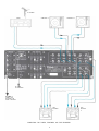
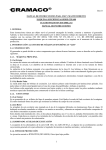
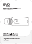
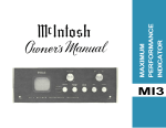
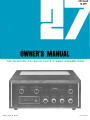
THE McINTOSH C27 SOLID STATE STEREO PREAMPLIFIER
Reading Time: 28 Minutes
Price: $2-00
WARNING: TO PREVENT FIRE OR SHOCK
HAZARD, DO NOT EXPOSE THIS UNIT TO
RAIN OR MOISTURE.
The Mclntosh you have purchased has a serial number located on
the rear panel of the chassis.
Record that serial number here
for future references. The model and serial number are important
to you for any future service.
Your C 27 Stereo Preamplifier will give you
many years of pleasant and satisfactory
performance. If you have any questions,
please contact:
Contents
SERVICE CONTRACT . . . . 1
CUSTOMER SERVICE
INTRODUCTION . . . . 2
Mclntosh Laboratory Inc.
2 Chambers Street
Binghamton, New York 13903
Phone: 607-723-3512
HOW TO INSTALL . . . .
HOW TO CONNECT . . . .
2
4
WHAT THE FRONT PANEL CONTROLS
AND HOW TO USE THEM . . . .
8
BALANCING YOUR STEREO . . . . 11
P E R F O R M A N C E LIMITS AND RATINGS . . . . 12
P E R F O R M A N C E CHARTS . . . . 13
Take Advantage of 3 years
of FREE Service . . .
Fill in the Application NOW.
TECHNICAL DESCRIPTION . . . . 14
BLOCK DIAGRAM . . . . 15
THREE YEAR SERVICE CONTRACT
An application for a FREE THREE YEAR SERVICE CONTRACT is included with this manual.
The terms of the contract are:
1. Mclntosh will provide ail parts, materials and
labor needed to return the measured performance of the instrument to the original performance limits free of any charge. The
SERVICE CONTRACT does not cover any
shipping costs to and from the authorized
service agency or the factory.
2. Any Mclntosh authorized service agency will
repair all Mclntosh instruments at normal
service rates. To receive the free service
under the terms of the SERVICE CONTRACT,
the SERVICE CONTRACT CERTIFICATE must
accompany the instrument when taken to
the service agency.
3. Always have service done by a Mclntosh
authorized service agency. If the instrument
is modified or damaged, as a result of unauthorized repair the SERVICE CONTRACT
will be cancelled. Damage by improper use or
Copyright © 1977 by Mclntosh Laboratory Inc.
mishandling is not covered by the SERVICE
CONTRACT.
4. The SERVICE CONTRACT is issued to you as
the original purchaser. To protect you from
misrepresentation this contract cannot be
transferred to a second owner.
5. For your protection Mclntosh selects only
dealers who have technical competence to
guide purchasers fairly, and provide service
when necessary. To receive the SERVICE
CONTRACT your purchase must be made
from a Mclntosh franchised dealer.
6. Your completely filled in application for a
SERVICE CONTRACT must be postmarked
within 30 days of the date of purchase of the
instrument.
7. To receive the SERVICE CONTRACT all information on the application must be filled
in. The SERVICE CONTRACT will be issued
when the completely filled in application is
received at Mclntosh Laboratory Incorporated
in Binghamton, New York.
How to Connect
CONNECTING A TURNTABLE TO PHONO 1
Connect the cable from the "left" channel of the turntable into the L PHONO 1 INPUT jack.
CONNECTING A STEREO TUNER
Connect the cable from the "left" channel tuner output
to the L TUNER INPUT jack.
Connect the cable from the "right" channel of the turntable into the R PHONO 1 INPUT jack.
Connect the cable from the "right" channel tuner output
to the R TUNER INPUT jack.
PHONO 2 is provided for the use of a second turntable.
AUX—Any high level program source such as a tuner,
a TV set or a tape recorder can be connected to the AUX 1
and 2 INPUT jacks. The connecting procedure is the same
as for the tuner input.
Connect the cable from the "left" channel of the turntable into the L PHONO 2 INPUT jack.
Connect the cable from the "right" channel of the turntable into the R PHONO 2 INPUT jack.
CONNECTING TAPE RECORDERS
To Record:
Connect a cable from the L TAPE 1 OUTPUT jack to the
left high level input of the tape recorder.
Plug the AC power cable from the turntable into the red
unswitched POWER outlet on the rear panel. The red
receptacle is on at all times. It is necessary to turn off the
turntable with its own AC power switch. This arrangement
protects the turntable.
Connect a cable from the R TAPE 1 OUTPUT jack to the
right high level input of the tape recorder.
Connect a second recorder in the same manner to the
TAPE 2 OUTPUT jacks.
The four black AC power outlets are controlled by the
front panel POWER switch. Use these outlets for a tuner,
tape recorder, etc.
To Playback/Monitor:
Connect a cable from the left channel output of a tape
recorder to the L TAPE 1 INPUT jack.
GROUND CONNECTION
A single ground post is provided. Grounds for turntables,
record changers, tape decks, etc. are to be connected to
this post. The left and right program cables and the ground
wire from that source should be wound or twisted together.
To avoid hum make sure the ground wire does not make
any connections to the shields of the left and right program
cables between the program source and the C 27.
Connect a cable from the right channel output of a tape
recorder to the R TAPE 1 INPUT jack.
Connect a second recorder in the same manner to the
TAPE 2 INPUT jacks.
4
FM ANTENNA
TUNER
TURNTABLE #1
TURNTABLE #2
AC POWER
TO TURNTABLES
AC POWER TO
TUNERS, TAPE
RECORDERS AND
POWER AMPLIFIERS
TAPE
RECORDER
1
CONNECTIONS FOR TUNERS, TURNTABLES, AND TAPE RECORDERS
5
TAPE
RECORDER
2
POWER AMPLIFIER
LOUDSPEAKER
ENVIRONMENTAL
EQUALIZER
SPEAKER SYSTEM #1
S P E A K E R SYSTEM #2
CONNECTIONS FOR POWER AMPLIFIER AND LOUDSPEAKERS
6
Connect a wire from the proper impedance output
connection on the power amplifier to the FROM AMPLIFIER
push connectors on the C 27 rear panel. Connect the first
pair of speakers to the rear panel SPEAKER 1 push connectors and a second pair of speakers to the SPEAKER 2
push connectors. When connecting the speakers and power
amplifier it is important to connect the power amplifier
output impedance tap for the parallel impedance combination of the two speaker systems used. The front panel
SPEAKER switch permits routing program to either
SPEAKER 1, SPEAKER 2, both 1 and 2, or OFF. In the
SPEAKER OFF position, the program is fed only to the
HEADPHONE jack for private listening.
CONNECTING THE C 27 TO POWER AMPLIFIERS
Connect the MAIN OUTPUT jacks to the input of a
stereo power amplifier. The Left MAIN jack is connected
to the left amplifier input jack. The Right MAIN jack is
connected to the right amplifier input jack.
A second pair of MAIN OUTPUT jacks have been supplied
to feed a second power amplifier. In the event it is desired
to tape record after the tone filter and volume controls
the second set of MAIN OUTPUT jacks can be connected
to the tape recorder input. The controls are then all available to alter the signal before recording. Remember, any
change in the setting of the controls will change the program to the tape recorder. Since the recording signal
available at the MAIN OUTPUT is much higher than the
output available from the TAPE 1 or TAPE 2 OUTPUT
jacks, be sure not to overload the tape recorder input. It
will not be possible to monitor from the tape recorder via
the TAPE MONITOR pushbuttons while feeding the recorder
from the MAIN OUTPUT jacks. Depressing the TAPE
MONITOR pushbutton will disconnect the program source
and may cause feedback oscillation.
AC OUTLETS
There are 4 black AC outlets and one red AC outlet. The
power to the black AC outlets is controlled by the front
panel AC power switch. Use these outlets for a tuner, tape
recorder, etc. The total capacity of all AC power outlets is
600 watts. The red receptacle is on at all times to feed
AC power to a turntable so that it can be turned on or off
with its own AC switch.
Cables are supplied with the C 27 to interconnect to
the power amplifier. Longer cables can be used if needed.
The length of the cable is limited by the capacity of the
cable. The total capacity must not exceed 1,000 pF. For
instance: cables with a capacity of 25 pF per foot may be
40 feet long. 13.5 pF per foot cable may be 75 feet long.
The input impedance of the amplifiers should be 22k
ohms or greater.
FUSE
A 0.5 AMP fuse protects the preamplifier circuits. The
fuse does not protect additional equipment connected to
the back panel AC outlets.
CTR CHAN
Use the CenTeR CHANnel output to feed left plus right
signal to a separate power amplifier for monophonic background music or for a center channel.
CONNECTING FOR SPEAKER SWITCHING AND
HEADPHONE
When the power amplifier output is properly connected
to the rear panel FROM AMPLIFIER push connectors,
speakers in two separate areas can be turned on or off
and the C 27 front panel HEADPHONE jack will receive
the program signal.
7
What the Front Panel controls Do
and How to use Them
INPUT SELECTOR
speakers. Stereo Rev: Connects the left input to the right
loudspeaker and the right input to the left loudspeaker.
The INPUT SELECTOR is a five position switch that
connects the chosen input program to the proper circuits
in the C 27.
Stereo: Connects the left input to the left loudspeaker
and the right input to the right loudspeaker.
AUX 1: Connects to the high level input, any output
from a high level program source requiring flat amplification. Such a source could be a television set, playback from
another tape recorder, an additional tuner, etc. In the
AUX 1 position the gain is 20 dB to the MAIN outputs,
0 dB to the TAPE outputs. The input impedance is 100 k
ohms.
Mono (L + R): Adds the left input and the right input
and then connects the L + R program to both loudspeakers.
L + R to L: Adds the left and right program together
and connects the combined program to the left loudspeaker only.
AUX 2: Same as AUX 1 but for a second high level
program source.
L + R to R: Adds the left and right program together
and connects the combined program to the right loudspeaker only.
TUNER: Connects the output from any AM, FM or MPX
FM tuner to the high level input stage. In the TUNER position the C 27 has flat amplification. There is 20 dB of
gain to the MAIN outputs, 0 dB to the TAPE outputs. The
input impedance is 100k ohms.
PRECISE TRACKING VOLUME CONTROL
The VOLUME control is a precision step attenuator
which has left to right tracking accuracy within 1 dB
throughout its entire range. Such extremely accurate matching is achieved through electronically controlled trimming
of the resistance material deposited on pairs of printed
circuits. Since the switch commutator touches only contact
pads and not the actual resistance element, tracking acc u r a c y is not degraded with use as in ordinary volume
controls. Clockwise rotation increases volume. The VOLUME
control in the C 27 has been designed and manufactured
for Mclntosh Laboratory.
PHONO 1: Connects the output of any magnetic phono
cartridge to the low level input stage. The response has
been shaped according to the RIAA standard to compensate
for the characteristics of a magnetic phono cartridge. The
gain at 1K Hz is 62 dB to the MAIN outputs, 42 dB to the
TAPE outputs. The input impedance is 47k ohms and
100 pF.
PHONO 2: Same as PHONO 1 but for a second phono
system.
FILTERS/SPEAKERS
The small center knob of the concentric FILTER/
SPEAKERS control shapes the C 27 frequency response to
reduce or filter objectionable low frequency noise and/or
objectionable high frequency noise. The large outer knob
MODE SELECTOR
L to L & R: Connects the left input to both loudspeakers. R to L & R: Connects the right input to both loud-
8
will turn main or remote loudspeakers on or off when a
power amplifier has been properly connected to the C 27
rear panel.
Right: Has the same effect on the sound from the right
loudspeaker.
TREBLE
Concentric, 11 position, tone control switches adjust
the treble. The outer knob adjusts the right channel response. The center knob adjusts the left channel treble
response.
FILTER OPERATION
OUT: Filter disconnected, program not modified by
either high or low frequency filters.
LF (LOW FREQUENCY FILTER)
Use the LF position to reduce objectionable lowfrequency noise created by a turntable or record changer
or acoustically coupled feedback. Response is rolled off
below 50 Hz.
Left: Adjusts the treble loudness from the left loudspeaker. Clockwise rotation increases the treble loudness
while counterclockwise rotation decreases the treble loudness. Each step of the tone control adjusts the treble
loudness about 4 dB.
HF (HIGH FREQUENCY FILTER)
Use the HF position to reduce objectionable highfrequency noise such as record scratch. Response is
rolled off above 5,000 Hz.
Right: Has the same effect on the sound from the right
loudspeaker.
LOUD/BALANCE
LOUDNESS:
Use the loudness control for full frequency range listening at even the softest listening levels. The LOUDness
control (the small center knob of the concentric control)
provides low-frequency boost to compensate for a hearing
characteristic of the human ear at low listening levels.
The ear becomes less sensitive to low frequencies as volume
is reduced. Increased loudness compensation is therefore
desirable at lower listening levels. The loudness control
boosts the low frequencies so that the ear hears approximately the same musical balance as it would at higher
listening levels.
LF-HF
Both high and low frequency filters are activated.
SPEAKERS
OPERATION
OUT: All speakers are disconnected. Program is fed only
to the HEADPHONE jack for private listening.
1: Program is fed only to the rear panel SPEAKER 1 connectors and the HEADPHONE jack. SPEAKER 2 is
disconnected.
1 & 2: Program is fed to the rear panel SPEAKER 1 and
2 connectors and the HEADPHONE jack.
2: Program material is fed only to the rear panel
SPEAKER 2 connectors and the HEADPHONE JACK.
SPEAKER 1 is disconnected.
FLAT: (Maximum counterclockwise rotation) Full volume
with flat frequency response. The loudness compensation
is inoperative in this position.
Turning the control clockwise toward MAX reduces the
listening volume, and automatically increases the compensation by boosting bass.
BASS
Concentric, 11 position, tone control switches adjust
the bass. The outer knob adjusts the right channel bass
response. The center knob adjusts the left channel bass
response.
BALANCE
The BALANCE control adjusts for unequal volume in
either the left or right channels. The volume of the channels can be varied relative to each other without affecting
their combined volume.
Left: Adjusts the bass loudness from the left loudspeaker.
Clockwise rotation increases the bass loudness while counterclockwise rotation decreases the bass loudness. Each
step of the tone control adjusts the bass loudness about 4
dB.
Turning the control to the left accents the left channel
9
by reducing the right channel output and turning the control to the right accents the right channel by reducing the
left channel output.
TAPE 2 MONITOR
A second tape recorder can be operated in the same
manner using pushbutton TAPE 2 MONITOR.
PANLOC
Depressing the two PANLOC buttons on the front panel
permits the C 27 to be either locked firmly in place or
unlocked so that the chassis can be slid forward, until it
is stopped by the mid-position latches. Press the latches
on the side of the C 27 inward to permit the instrument to
slide in or out of the cabinet. With the C 27 front panel
flush with the cabinet panel, pressing the PANLOC buttons
will lock the unit firmly in the cabinet.
Use the front panel pushbutton TAPE 2 to playback from
a tape recorder plugged into the rear panel TAPE 2 INPUT
jacks.
HOW TO COPY TAPE, TAPE COPY 1 -> 2
Put the tape to be copied on the recorder connected to
TAPE 1 INPUT. Press in the TAPE COPY 1 -> 2 pushbutton.
The signal available at the TAPE 2 OUTPUT jacks is the
playback of TAPE 1. Record on the recorder connected to
TAPE 2 OUTPUT. The source tape on tape recorder 1 can
be heard by pressing in the TAPE 1 MONITOR pushbutton.
The recording can be monitored by pressing in the TAPE 2
MONITOR pushbutton. Instantaneous comparison on the
recorded program with the original can be heard.
THE PUSHBUTTONS
The C 27 is designed to be used with one or two tape
recorders. The front panel pushbuttons permit normal
playback of either recorder, monitor as recordings are
being made on either recorder, or copying tapes from one
recorder to another while listening to a separate program.
TAPE COPY 2 -> 1
When pushed IN the TAPE 2 OUTPUT jacks are connected to the TAPE 1 INPUT jacks without affecting the
program heard from the speakers. In this position a copy
of the program on tape recorder 2 can be made on tape
recorder 1.
TAPE MONITOR
To monitor while recording from any source chosen on
the INPUT SELECTOR, your tape recorder must have separate record and playback heads and separate electronics.
The MONITOR switches let you monitor the quality of tape
recordings made during the recording process. When the
chosen TAPE MONITOR pushbutton is in the IN position
the sound from the tape as it passes the playback head is
heard a moment after it is recorded. The recording process
continues as usual. When the switch is in the OUT position,
the program that is being recorded is heard.
To monitor the tape copy procedures use the TAPE
MONITOR pushbuttons.
POWER
The POWER switch energizes the C 27 circuits and connects AC power to the black rear panel AC power outlets.
The black AC power outlets are not fused. A lighted rectangle above the ON POWER switch indicates the AC
power to the system is turned on.
TAPE 1 MONITOR
PUSHBUTTON OUT . . . The program source selection by
the INPUT SELECTOR is fed to the power amplifiers and
heard through the loudspeakers.
HEADPHONES
The front panel HEADPHONE jack has been designed to
feed low impedance dynamic headphones. Electrostatic
headphones generally require higher power than dynamic
headphones. They must be connected to the output connectors on the power amplifier.
PUSHBUTTON IN . . . The program source becomes the
recorded tape on the recorder connected to TAPE 1 INPUT.
The recorded program from tape recorder 1 is fed to the
power amplifiers and heard from the loudspeakers.
Plug headphones into the front panel HEADPHONE
jack. Adjust the VOLUME control for comfortable headphone listening. The output of an external power amplifier
must be properly connected to the C 27 back panel for
program material to be available at the HEADPHONE jack.
In the PUSHBUTTON IN position, a rectangle is lighted
above the pushbutton. When the light is on only the tape
will be heard. To listen to other sources the pushbutton
must be out and the light off.
10
Balancing your Stereo
The performance and enjoyment of a stereo system is
greatly increased when the sound is properly balanced.
The balance of the stereo system is affected by many
things including room acoustics, furniture placement, room
shape, small differences in loudspeakers etc.
speakers. If there is a difference in loudness turn the
BALANCE control to adjust for equal loudness.
Clockwise rotation balances for lack of loudness on the
right—conterclockwise balances for lack of loudness on
the left, Next, set the MODE selector to STEREO. If there
is then a difference in loudness turn the BALANCE control
toward the speaker that is not as loud. Adjust until the
sound is balanced from both speakers.
TO BALANCE LOUDNESS
1. Set the MODE switch to MONO (L + R]
2. Play a familiar recording.
3. Turn the BALANCE control to the 10 o'clock position.
While the program is playing, stand between the two
loudspeakers. Listen for a difference in loudness between
11
Performance Limits and Ratings
MOUNTING: Exclusive Mclntosh developed professional
PANLOC.
PERFORMANCE LIMITS are the maximum deviation from
perfection permitted for a Mclntosh instrument. We promise
you that your C 27 must be capable of performance at or
exceeding these limits or you get your money back. Mclntosh is the only manufacturer that makes this guarantee.
WEIGHT: 20 pounds (9.1 kg) net, 32 pounds (14.5 kg) in
shipping carton.
FACILITIES AND FEATURES
BASS
Separate 11 position rotary switches for each channel.
-17 dB to +16 dB at 20 Hz
TREBLE
Separate 11 position rotary switches for each channel
-20 dB to +20 dB at 20k Hz
FREQUENCY RESPONSE
+0 -0.5 dB 20 Hz to 20k Hz
DISTORTION
Will not exceed 0.05% at rated output level, 20 Hz to 20k
Hz
INPUT SENSITIVITY AND IMPEDANCE
AUXILIARY i and 2, TUNER, TAPE 1 and 2: 250 millivolts
at 100k ohms. PHONO 1 and 2: 2 millivolts at 47k ohms
and 100 pF.
HUM AND NOISE
AUXILIARY 1 and 2, TUNER, TAPE 1 and 2: 85 dB unweighted; 90 dB IHF A weighted.
PHONO 1 and 2: 80 dB below 10 mV input, unweighted;
85 dB IHF A weighted.
OUTPUT LEVEL AND IMPEDANCE
MAIN OUTPUT 2.5 volts with rated input, less than 1k
ohms source impedance, to operate into 22k ohms load
or higher. Maximum output is greater than 10 volts
TAPE OUTPUT 0.25 volts with rated input, less than 1.5k
ohms source impedance, to operate into 22k ohms load
or higher. Maximum output is greater than 10 volts
CENTER CHANNEL OUTPUT (L + R) 2.5 volts with rated
input to both channels, less than 1.2k ohms source impedance, to operate into 22k ohms load or higher.
VOLTAGE AMPLIFICATION IN DECIBELS
AUXILIARY 1 and 2, TUNER, TAPE 1 and 2
to MAIN OUTPUT
20 dB
to TAPE OUTPUT
0 dB
PHONO 1 and 2
to MAIN OUTPUT
62 dB
to TAPE OUTPUT
42 dB
SEMICONDUCTOR COMPLEMENT
18 Silicon—Planar transistors
4 Silicon Diodes
5 Light Emitting diodes
AC POWER OUTLETS
1 unswitched (Red)
4 switched
POWER REQUIREMENT
120 volts, 50/60 Hz, 15 watts
MECHANICAL INFORMATION
SIZE: Front Panel measures 16 inches wide (40.6 cm) by 5
7/16 inches high (13.8 cm). Chassis measures 14 3/4 inches wide (37.5 cm) by 4 13/16 inches high (12.2 cm) by 13
inches deep (30.0 cm), including PANLOC shelf and back
panel connectors. Knob clearance required is 1 1/4 inches
(3.2 cm) in front of the mounting panel.
LOUDNESS
Flat response, or continuously variable loudness equalization.
BALANCE
Natural balance at center position, attenuation of left or
right channel by rotating control
VOLUME
Precision step attenuator with matched elements for proper
tracking at all listening levels. Does not change stereo
balance as volume is changed.
INPUT
Five positions—AUXILIARY 1 and 2, TUNER, PHONO 1
and 2
MODE
Seven positions—Left channel only to both speakers. Right
channel only to both speakers, STEREO REVerse, STEREO,
MONO (L + R), L + R to Left speaker only, and L + R to
Right speaker only
TAPE MONITOR
Two pushbutton switches. Either of two tape recorders can
be monitored. They are mechanically interlocked to accept
only one pushbutton at the IN position at one time
TAPE COPY SWITCH
Two pushbutton switches. Either of two tape recorders can
be connected to copy from one to the other or vice versa.
They are mechanically interlocked to accept only one
pushbutton at the IN position at one time.
LF FILTER (Rumble Filter)
Flat or roll-off 12 dB per octave below 50 Hz, down 12 dB at
20 Hz
HF FILTER (Scratch Filter)
Flat or roll-off 12 dB per octave above 5k Hz. down 12 dB at
20 k Hz
SPEAKER SWITCH
Facilities are provided to connect the power amplifier to
the rear panel of the C 27 to permit switching two pairs
of speakers on and off.
FINISH: Front panel is anodized gold and black with
special Mclntosh gold/teal panel nomenclature illumination. Chassis is black.
HEADPHONE JACK
For low impedance headphones; powered by properly interconnected external power amplifier.
12
13
Technical Description
The accompanying BLOCK DIAGRAM indicates the
various signal paths within the C 27. Circuits represented
by each block are discussed below.
a 32-step control with a 70 dB range, plus volume off.
Left and right channel tracking are within 1 dB. This extreme accuracy is obtained through special electronically
controlled resistance element trimming. Since the switch
commutator touches only contact pads and not the precision resistor elements, tracking accuracy is permanently
maintained and is noise free.
INPUT SELECTOR SWITCH
The INPUT SELECTOR routes the various input signals
within the C 27. The switch is robust in construction and
has large double wiping silver contacts. Isolating networks
at each high level input and shorting switch action ground
all unused inputs preventing undesired program feedthrough. The same isolating networks block any DC that
might be present on a high level input to eliminate pops
or clicks when changing inputs.
VOLTAGE AMPLIFIER
A voltage amplifier with 14 dB gain follows the VOLUME
control. This amplifier plus the following amplifier with
6 dB gam constitute the main amplifier section of the C 27.
The amplifier has high input impedance, low output impedance, very low noise level and wide dynamic range.
PHONO PREAMPLIFIER
Each channel of the phono preamplifier uses three
discrete transistors especially selected, and circuit optimized, to produce low noise and distortion free operation.
Of particular benefit is the use of low impedance components in the RIAA feedback equalization networks. The
network drive is provided by the final stage transistor
which operates at an adequate current level to drive the
low impedance without slew rate limiting.
HIGH FREQUENCY AND LOW FREQUENCY FILTERS
The HF and LF FILTER networks are switch controlled.
The high-frequency filter network reduces treble response
above 5,000 Hz. The low-frequency filter reduces bass
response below 50 Hz. The slope of the filter frequency
response is selected for maximum rejection of objectionable
noises. Careful design has kept the loss of usable program
material to a minimum.
MONITOR AND TAPE COPY SWITCHES
Tape switching uses pushbutton switches. The switches
are mounted directly to a printed circuit board that incorporates the necessary inter-connection wiring. Isolating
networks are included at each tape input and output
which eliminates the possibility of DC leakage from associated tape recorders which prevent pops or clicks when
switching. The pushbutton switches have reliable pushpush action ratchets to prevent switch hangup. Light
emitting diode (LED) lamps are activated by the switches
to indicate the particular switch function being used.
LOUDNESS CONTROL
The LOUDness control is continuously variable. Full
volume and flat frequency response is obtained in the
counterclockwise or FLAT position of this control. As the
control is advanced clockwise the volume level reduces
but loudness compensation is introduced which maintains
the low-frequency output at a higher level than the mid
and high frequency output. This action complements the
human ear response characteristics, the Fletcher Munson
effect. Loudness compensation is provided for a wide range
of listening levels.
MODE SWITCH
A seven-position MODE SELECTOR switch allows routing
of the left and right channel signals in various combinations for system balancing and operation. The MODE SELECTOR functions only in the signal path directed through
the MAIN OUTPUT jacks and does not control the TAPE
OUTPUT.
BALANCE CONTROL
Rotating the BALANCE control to the left or right allows
you to balance the level of the two channels. At the detented center position the gain of the two channels is equal.
BASS AND TREBLE CONTROLS AND ASSOCIATED
AMPLIFIER
A high gain three stage linear amplifier is used in the
bass and treble control circuits. Negative feedback reduces
the gam to 6 dB when the controls are set flat. The feedback path incorporates the control response shaping net-
VOLUME CONTROL
The VOLUME control is a precision step attenuator
designed and manufactured for Mclntosh Laboratory. It is
14
15
works. Separate BASS and TREBLE controls route the
feedback signal to shape the frequency response by varying
the amount of feedback used at different frequencies.
Accurate control is accomplished by using precision capacitors and resistors. The output of this amplifier is fed to
the MAIN OUTPUT jacks.
CENTER CHANNEL AMPLIFIER
The CTR CHAN (center channel) amplifier is an emitter
follower arranged for very high input impedance. Unity
gain is provided at the CTR CHANnel OUTPUT jack when
both the LEFT and RIGHT channels have equal output
signals.
POWER SWITCH AND POWER OUTLETS
The pushbutton POWER switch controls AC power to
the C 27 and the four black switched outlets. Power to
the red unswitched outlet is present all the time and is
not controlled by the power switch. The red outlet is intended to power turntables. The switched outlets are used
to power tuners, power amplifiers, and similar components.
POWER TRANSFORMER AND POWER SUPPLY
The C 27 power transformer uses a grain oriented silicon
steel core plus copper and magnetic steel shield bands to
eliminate any radiated magnetic hum field. The extra care
in shielding assures that the power transformer will not
radiate an external magnetic field that could introduce
hum into the amplifier circuits or an adjacent phono pickup
cartridge or tape recorder playback head.
The power supply uses zener diode reference voltage
regulation and electronic filtering. Normal power line
variations do not affect the performance of the C 27. The
turn on and off time characteristics of the power supply
are controlled to prevent turn on and off transients.
SPEAKER SWITCH AND HEADPHONE JACK
The SPEAKER switch is arranged to control two sets of
loudspeakers powered by an external power amplifier.
When connecting the speakers and power amplifier it is
important to connect the power amplifier output impedance tap to the parallel impedance of the two speaker
systems used. The headphone jack is also fed from the
external power amplifier. The power amplifier is required
to make the HEADPHONE jack operate.
16
MclNTOSH LABORATORY INC.
2 CHAMBERS ST. BINGHAMTON, N. Y. 13903
607-723-3512
The continuous improvement of its products is the policy of
Mclntosh Laboratory Incorporated, who reserve the right to
improve design without notice.
Printed in U.S A.
339091