1
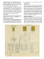
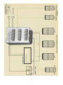
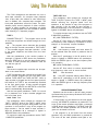
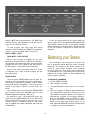
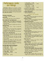
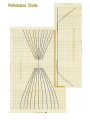
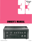
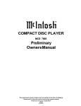
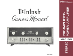
THE MCINTOSH C 28 SOLID STATE STEREO PREAMPLIFIER
Reading Time: 37 Minutes
Price $1.25
Your MC 28 Stereo Preamplifier
will give you many years of pleasant
and satisfactory performance. If you
have any questions, please contact:
CONTENTS
Service Contract.. 1
Installation.. 2, 3
How to Connect.. 4, 5, 6, 7
Adjusting The Top Panel Controls.. 8
CUSTOMER SERVICE
Mclntosh Laboratory Inc.
2 Chambers Street
Binghamton, New York 13903
Phone: 607-723-3512
Using The Front Panel Controls.. 9, 10
Using the Pushbuttons.. 11
WARNING: TO PREVENT FIRE OR SHOCK
HAZARD, DO NOT EXPOSE THIS UNIT TO RAIN
OR MOISTURE.
Balancing Your Stereo .. 12, 13
Listening To Your Stereo.. 13
Performance Limits and Ratings .. 14, 15
Performance Charts.. 16
Take Advantage of 3 years
of FREE Service . . .
Fill in the Application NOW.
Technical Description.. 18
Block Diagram .. 20
THREE YEAR SERVICE CONTRACT
An application for a FREE THREE YEAR SERVICE CONTRACT is included with this manual.
The terms of the contract are:
or mishandling is not covered by the SERVICE CONTRACT.
4. The SERVICE CONTRACT is issued to you as
the original purchaser. To protect you from
misrepresentation this contract cannot be
transferred to a second owner.
1. Mclntosh will provide all parts, materials and
labor needed to return the measured performance of the instrument to the original performance limits free of any charge. The
SERVICE CONTRACT does not cover any shipping costs to and from the authorized service
agency or the factory.
5. For your protection Mclntosh selects only
dealers who have technical competence to
guide purchasers fairly, and provide service
when necessary. To receive the SERVICE
CONTRACT your purchase must be made
from a Mclntosh franchised dealer.
2. Any Mclntosh authorized service agency will
repair all Mclntosh instruments at normal
service rates. To receive the free service under
the terms of the SERVICE CONTRACT, the
SERVICE CONTRACT CERTIFICATE must accompany the instrument when taken to the
service agency.
6. Your completely filled in application for a
SERVICE CONTRACT must be postmarked
within 30 days of the date of purchase of
the instrument.
7. To receive the SERVICE CONTRACT all information on the application must be filled
in. The SERVICE CONTRACT will be issued
when the completely filled in application
is received at Mclntosh Laboratory Incorporated in Binghamton, New York.
3. Always have service done by a Mclntosh
authorized service agency. If the instrument
is modified or damaged, as a result of unauthorized repair the SERVICE CONTRACT
will be cancelled. Damage by improper use
1
Copyright (c) 1970 By Mclntosh Laboratory Inc.
How To Connect
CONNECTING A RECORD PLAYER TO PHONO 1
Connect the cable from the "left" channel of the
record player into the "L" PHONO 1 input jack.
Connect the cable from the "right" channel of the
record player into the "R" PHONO 1 jack.
PHONO 2 is provided for the use of a second record
player.
Connect the cable from the "left" channel of the
record player into the "L" PHONO 2 input jack.
Connect the cable from the "right" channel of the
record player into the "R" PHONO 2 input jack.
CONNECTING A MICROPHONE
Connect the cable from the "left" microphone to
the "L" MIC input jack. Connect the cable from the
"right" microphone to the "R" MIC input jack.
CONNECTING A TAPE DECK FOR PLAYBACK
Connect the cable from the "left" tape recorder head
on the tape deck (one without its own electronics)
to the "L" TAPE HEAD input. Connect the cable
from the "right" tape recorder head to the "R" TAPE
HEAD input.
CONNECTING A STEREO TUNER
Connect the cable from the "left" channel tuner output to the "L" tuner input jack.
Connect the cable from the "right" channel tuner
output to the "R" TUNER jack.
AUX
Any high level program source such as another tuner
or a TV set can be connected to the input jacks
marked "AUX."
CONNECTING A TAPE RECORDER
To Record:
Connect a cable from the "L" TAPE OUTPUT jack
marked TAPE 1 to the "left" high level input tape
recorder.
Connect a cable from the "R" TAPE OUTPUT jack
marked TAPE 1 to the "right" high level input of the
tape recorder.
Connect a second tape recorder in the same fashion
to the TAPE 2 outputs.
To Playback Monitor: Connect the cable from the
"left" channel output of a tape recorder to the high
level inputs . . . "L" TAPE 1.
Connect the cable from the "right" channel output of
a tape recorder to the high level input . . . "R" TAPE.
Connect a second tape recorder in the same fashion
to the TAPE 2 input jacks.
4
5
trol. The AC outlets on the SCR have a total capacity of 2400 watts.
CONNECTING THE C 28 TO POWER AMPLIFIERS
Connect the MAIN output jacks to the input of a
stereo power amplifier. The "L" jack is connected to
the "left" amplifier input jack. The "R" jack is connected to the "right" amplifier input jack.
AC OUTLETS
There are 4 black AC outlets, 2 green AC outlets,
and one red AC outlet. The power to the black AC
outlets is controlled by the front panel switch. Use
these outlets for a tuner, tape recorder, etc. The
green outlets are controlled by the top panel switch
marked "Power Amplifier." The total capacity of all
AC power outlets is 600 watts. To prevent burnout,
use the AC outlets on the CR for power requirements
exceeding 600 watts. The red receptacle is on at all
times. Use the red outlet for a turntable or record
changer. The turntable is protected by this arrangement. It is necessary to turn off the turntable or record changer with its own AC switch.
The output impedance at the MAIN outlet is 100
ohms. Longer cables than are supplied can be connected between the C 28 and the amplifiers. The
length of the cable is limited by the capacity of the
cable. The total capacity must not exceed 1000 pF.
For instance: cables with a capacity of 25 pF per
foot may be 40 feet long. 13.5 pF per foot cable
may be 75 feet long. The input impedance of the
amplifiers should be 47,000 ohms or greater.
CTR OUTPUT
Use the CTR output to feed left plus right signal to a
separate power amplifier for monophonic background music or for a center channel speaker.
GROUND CONNECTION
A single ground post is provided. Grounds for turntables, record changers, tape decks, etc. should be
connected to this post. The left and right program
cables and the ground wire from that source should
be wound or twisted together. To avoid hum, make
sure the ground wire does not make any connections to the shields of the left and right program
cables between the program source and the C 28.
SPEAKER CONTROL RELAY
To control main and remote loudspeakers from the
front panel of the C 28 an accessory Mclntosh SCR
control is needed. Plug the cable from the SCR control in the SPEAKER CONTROL RELAY receptacle.
The speakers are then connected to the SCR con-
6
7
Adjusting The Top Panel Controls
You will enjoy the best in stereo performance more
when the stereo system is properly balanced. For
proper balance each channel must be equal in loudness and similar in frequency response. Use the top
panel LEVEL controls to balance system loudness
and the top panel BASS TRIM controls to balance for
frequency response differences at low frequencies.
sponse at low frequencies or for the room in which
they are used. They are variable controls that provide
up to 6 dB of boost below 100 Hz. With the control
in the counter-clockwise position the response is flat.
Clockwise rotation increases the bass loudness. Adjust one channel at a time.
Do not use the front panel BALANCE control to
correct for system unbalance. The BALANCE control
is used to adjust for any unbalance in the source
material, the record, etc.
A control has been provided in each channel to
adjust the loudness of the program when using headphones. The controls adjust the output in each channel to the HEADPHONE jack only and do not affect
the program loudness from the loudspeakers. To adjust for comfortable headphone listening first adjust
the VOLUME control to the front panel to normal
room loudness. Then, while wearing the headphones,
adjust the HEADPHONE LEVEL control to the desired
loudness level.
Headphone Level
Before attempting to balance the output of the C 28
make certain the front panel controls are set properly.
Turn the VOLUME control to the OFF (totally counter-clockwise) position.
Set the MODE SELECTOR to STEREO and the
BALANCE control at the center or 12 o'clock position.
Turn the tone controls to the center or 12 o'clock
position. The HF and LF pushbuttons should be in
the OUT position and the COMPensation control in
the FLAT position. Turn the INPUT SELECTOR to
TUNER.
Output Level
A control has been provided in each channel that
adjusts the output of the preamplifier. Use these controls to compensate for minor differences in loudspeaker efficiency or amplifier gain. These controls
adjust the level to the MAIN OUTPUTS only.
Depress the PANLOC buttons and pull the preamplifier out to the adjust position. The controls on
the top panel are now easily adjusted.
With the MODE SELECTOR in the MONO (L + R)
position set the BALANCE control to 12 o'clock. Adjust the top panel OUTPUT LEVEL controls until the
loudness from each loudspeaker is equal.
On the top panel turn the BASS TRIM controls
counter-clockwise. Turn all the level controls to the
clockwise position. Turn the POWER AMPLIFIER
switch on.
Center Channel Level
A control has been provided that adjusts the combined left plus right program level to the CTR output
jacks.
With the tuner turned on, turn up the VOLUME
control on the front panel until a comfortable room
loudness is reached.
Power Amplifier On/Off
Then switch the INPUT SELECTOR to PHONO 1,
the MODE SELECTOR to L TO L & R, use a monophonic record and turn down the top panel LEFT
PHONO 1 LEVEL control to match the loudness of the
tuner. Repeat the procedure with the RIGHT PHONO
1 LEVEL control. When the channels are equally loud
the system is balanced for loudness.
A switch has been provided that will control the
AC power to the green POWER AMPLIFIER receptacles independently of the C 28 front panel control.
Use this switch to turn off the amplifier when listening to the headphones, etc.
IMPORTANT: TO HEAR THE PROGRAM FROM THE
LOUDSPEAKERS THIS SWITCH MUST BE IN THE
ON POSITION.
Repeat the same steps for PHONO 2.
Bass Trim
A control has been provided in each channel that
adjusts the bass loudness. These controls are used
to compensate for the differences in loudspeaker re-
8
Using The Front Panel Controls
Tuner: Connects the output from any AM, FM or
MPX FM tuner to the high level input stage. In the
TUNER position the C 28 has flat amplification.
There is 20 dB of gain to the MAIN outputs, 0 dB
to the TAPE outputs and 17.5 dB to the LINE outputs. The input impedance is 250,000 ohms.
Phono 1: Connects the output of any magnetic
phono cartridge to the low level input stage. The
response has been shaped to compensate for the
characteristics of the magnetic phono cartridge.
The gain at 1,000 Hz is 62 dB to the MAIN outputs,
42 dB to the TAPE outputs and 59.5 dB to the LINE
outputs. The input impedance is 47,000 ohms.
In the upper left of the front panel is a concentric
control. The large outer knob is the BALANCE control. The small center knob is the COMPENSATION
control.
BALANCE
The BALANCE control adjusts for unequal loudness in either the left or right channels. The loudness of the channels can be varied relative to each
other without affecting their combined loudness.
Left . . . turning the control to the left accents the
left channel by reducing the right channel output.
Right . . . turning the control to the right accents
the right channel by reducing the left channel output.
Phono 2: Same as PHONO 1.
Mic: Connects the output of any high impedance
microphone to the low level input stage. In the MIC
position the C 28 has flat amplification. The gain
is 60 dB to the MAIN outputs, 40 dB to the TAPE
outputs and 57.5 dB to the LINE outputs. The input
impedance is 500,000 ohms.
Tape Hd: Connects the output of any tape head (a
tape deck without its own electronics) to the low
level input stages. The response has been shaped
to compensate for the characteristics of the tape
head. The gain at 500 Hz is 64 dB to the MAIN outputs, 44 dB to the TAPE outputs and 61.5 dB to the
LINE outputs. The input impedance is 500,000
ohms.
COMPENSATION
The COMPENSATION control is a three position
switch.
Pres: In the left of center position the response of
the C28 is shaped to emphasize the upper midfrequencies.
Flat: In the center position the response of the C 28
is unmodified.
Loud: The LOUDness control automatically provides the correct amount of bass required to compensate for the change in response of the human
ear at low loudness levels.
MODE SELECTOR Connects the program to the
loudspeaker in the following seven ways:
When the volume is reduced, the music will
seem to lose much of its bass and some of its
treble. This effect is due to the sensitivity characteristic of human hearing. The response of the human ear to bass and treble pitch decreases more
rapidly than its response to pitch centered in the
mid-tonal range. The LOUDness switch converts
the volume control to a loudness compensated
control. Use LOUDness to listen at low volume and
still hear full-frequency range.
L to L & R: Connects the "left" input to both loudspeakers.
R to L & R: Connects the "right" input to both loudspeakers.
Stereo Rev: Connects the "left" input to the "right"
loudspeaker and the "right" input to the "left"
loudspeaker.
Stereo: Connects the "left" input to the "left" loudspeaker and the "right" input to the "right" loudspeaker.
INPUT SELECTOR
Mono (L + R): adds the "left" input and the "right"
input and then connects the L + R program to both
amplifiers and loudspeakers.
Aux: Connects the output from any high level program source requiring flat amplification to the high
level input stage. Such a source could be a television set. In the AUX position the gain is 20 dB to
the MAIN outputs, 0 dB to the TAPE outputs, and
17.5 dB to the LINE outputs. The input impedance
is 250,000 ohms.
L + R to L: Connects the "left plus right" program
to the "left" loudspeaker only.
L + R to R: Connects the "left plus right" program
to the "right" loudspeaker only.
9
TREBLE
VOLUME ON/OFF
Turning the VOLUME totally counter-clockwise
turns the C28 OFF. The VOLUME control regulates
the loudness in both channels. The VOLUME control has been precision tracked throughout the listening range (0 to -65 dB) for accurate stereo
balance.
Left: Adjusts the treble loudness from the left loudspeaker. Clockwise rotation increases the treble
loudness while counterclockwise rotation decreases the treble loudness. Each step of the tone
control adjusts the treble loudness about 4 dB.
Right: Has the same effect on the sound from the
right loudspeaker.
BASS
PANLOC
The C 28 has separate 11 position tone control
switches in each channel for bass and treble.
Mclntosh developed PANLOC mounting brings professional installation technique to stereo. Depressing the PANLOC button fas with a ball point pen)
will release the instrument. It can then be pulled
toward you to the "adjustment" position. In this
position the top panel controls can be adjusted.
Left: Adjusts the bass loudness from the left loudspeaker. Clockwise rotation increases the bass
loudness while counter-clockwise rotation decreases the bass loudness. Each step of the tone
control adjusts the bass loudness 4 dB.
Right: Has the same effect on the sound from the
right loudspeaker.
10
Using The Pushbuttons
The C 28 is designed to be used with one, two or
three tape recorders, for example—tape playback
from a tape deck (one without its own electronics)
and, in addition, two complete tape recorders. The
front panel pushbuttons control the latter. The pushbuttons permit normal playback of either recorder,
monitor of either recorder as recordings are being
made, or copying tapes from one recorder to another
while listening to a separate program.
TAPE COPY 2->1
This pushbutton, when pushed IN, connects the
TAPE 2 OUTPUT jacks to the TAPE 1 INPUT jacks
without affecting the program heard from the
speakers. In this position a copy of the program on
tape recorder 2 can be made on tape recorder 1.
With the pushbutton in the IN position a rectangle is
lighted in ORANGE above the pushbutton.
To monitor the tape copy procedures use the TAPE
2 MONITOR pushbutton.
TAPE 1
LF (LOW FREQUENCY FILTER)
PUSHBUTTON OUT ... The program source is fed
to the power amplifiers and heard through the loudspeakers.
Use the LF filter switch to reduce objectionable
low-frequency noise created by a turntable or record
changer or acoustically coupled feedback.
IN . . . The program source becomes the recorded
tape on the tape recorder connected to TAPE INPUT
1. The recorded program from tape recorder 1 is fed
to the power amplifiers and heard from the loudspeakers.
OUT . . . filter disconnected.
IN ... low-frequency rumble and noise below 50
Hz are reduced when the switch is pushed to the IN
position.
With the pushbuttons in the monitor position a
rectangle is lighted in RED above the pushbutton.
When the RED light is on only the tape can be heard.
To listen to other sources the pushbutton must be
out and the light off.
With the LF pushbutton in the IN position a rectangle is lighted in GREEN above the pushbutton.
When the GREEN light is on the low frequency filter
is in operation.
HF (HIGH FREQUENCY FILTER)
TAPE 2
Use the HF filter switch to reduce objectionable
high-frequency noise such as record scratch.
The second complete tape recorder can be operated in the same fashion.
OUT . . . filter disconnect
TAPE 2 pushbutton also controls the program from
a tape recorder plugged into the front panel jacks
marked TAPE INPUT and TAPE OUTPUT. When a
tape recorder is plugged into the front panel jacks all
the facilities for TAPE 2 are automatically switched
to the front panel packs. A tape recorder plugged
into the TAPE 2 INPUTS and OUTPUTS on the back
panel is automatically disconnected.
IN . . . rolls OFF response sharply above 7000 Hz
With the HF pushbutton in the IN position a rectangle is lighted in GREEN above the pushbutton.
When the GREEN light is on the high frequency filter
is in operation.
SPEAKER PUSHBUTTONS
Use the front panel pushbutton TAPE 2 to record
on or playback from a tape recorder plugged into
the front panel jacks.
Speakers can be turned on and off when properly
connected with the accessory Mclntosh SCR control.
(See diagram Pg. 7)
TAPE COPY 1->2
If the program is to be heard from the main speakers only, the REMOTE pushbutton is pushed IN. This
turns off the remote speakers and lights a rectangle
in BLUE above the pushbutton. The BLUE light indicates that the remote speakers are off and no program can be heard from them.
This pushbutton, when pushed IN, connects the
TAPE 1 OUTPUT jacks to the TAPE 2 INPUT jacks
without affecting the program being heard from the
speakers. In this position a copy of the program on
tape recorder 1 can be made on tape recorder 2.
With the pushbutton IN a rectangle is lighted in
ORANGE above the pushbutton.
If the program is to be heard from the remote
speakers only the MAIN pushbutton is pushed IN.
This turns off the main speakers and lights a rec-
To monitor the tape copy procedures use the TAPE
1 MONITOR pushbutton.
11
To turn the power amplifiers off use the switch on
the top panel of the C 28 marked POWER AMPLIFIER.
This switch controls the AC to the green POWER
AMP receptacles on the back panel. With this switch
in the OFF position nothing will be heard from the
speakers.
tangle in BLUE above the pushbutton. The BLUE light
indicates that the main speakers are off and no program can be heard from them.
To hear program from both main and remote
speakers, both the MAIN and REMOTE pushbuttons
must be out and the BLUE lights must be off.
FRONT PANEL JACKS
Balancing your Stereo
TAPE INPUT - TAPE OUTPUT
When a tape recorder is plugged into the front
panel jacks all the facilities for TAPE 2 are automatically switched to the front panel jacks. A tape recorder
plugged into the TAPE 2 INPUTS and OUTPUTS on
the back panel is automatically disconnected.
The performance and enjoyment of a stereo system is greatly increased when the sound is properly
balanced. The balance of the stereo system is affected by many things including room acoustics,
furniture placement, room shape, small differences
in loudspeakers, etc. Factors that affect proper stereo
balance are correct phase for both channels and
equal program loudness.
Use the front panel pushbutton TAPE 2 to record
or playback from a tape recorder plugged into the
front panel jacks.
HEADPHONES
The front panel HEADPHONE jack has been designed to feed low impedance dynamic headphones.
Electrostatic headphones generally require higher
power than dynamic headphones. They must be connected to the output connectors on the power amplifier.
TO BALANCE LOUDNESS
Plug headphones into the front panel HEADPHONE
jack. Adjust the front panel VOLUME control for comfortable headphone listening. (See Pg. 8}
4. While the program is playing, stand between the
two loudspeakers. Listen for a difference in loudness between speakers. Balance the system by
adjusting the controls on the power amplifiers.
Next, set the MODE selector to STEREO. If there
is then a difference in loudness turn the BALANCE control toward the speaker that is not as
loud. Adjust the BALANCE control until the sound
is equally loud from both speakers.
1. Set the MODE to MONO.
2. Play a familiar recording.
3. Turn the BALANCE control to the 12 o'clock position.
An amplifier in the C 28 provides the power that
feeds both the HEADPHONE jack on the front panel
and the LINE OUTPUT jacks on the rear panel. If you
choose to listen to headphones only it is not necessary to operate the power amplifiers that feed the
loudspeakers.
12
Listening to your Stereo
ing in the TAPE 2 pushbutton. Instantaneous comparison on the recorded program with the original
can be heard.
LISTENING TO STEREO RECORDS
Turn the INPUT SELECTOR to PHONO 1, or
PHONO 2, whichever is connected to the record
player you wish to hear.
LISTENING TO TAPE DECKS
To listen to tape from a tape deck, proceed as follows:
Set the MODE SELECTOR to STEREO.
Adjust the VOLUME control to the desired volume.
Turn the INPUT SELECTOR to TAPE HEAD.
LISTENING TO MONOPHONIC RECORDS
Turn the MODE SELECTOR to MONO (L + R) or
STEREO, depending on the program on the tape.
Turn the INPUT SELECTOR to PHONO 1, or
PHONO 2, whichever is connected to the record
player you wish to hear.
Adjust the VOLUME control to the desired volume.
USING MICROPHONES
Turn the MODE SELECTOR to MONO.
Microphones in stereo may be used with the C28.
The two MIC channels amplify microphone signals.
They have a sensitivity of 2.5 millivolts and an input
impedance of 0.5 megohm. For lower output microphones input transformers should be used to raise
the voltage output to the 2.5 millivolt range.
Adjust the VOLUME control to the desired volume.
LISTENING TO A TUNER
Turn the INPUT SELECTOR to TUNER.
Adjust the volume to a comfortable level.
LISTENING TO A TAPE RECORDER
Two tape recorders can be used with the C 28.
Connect a three head tape recorder to TAPE 1 inputs.
Connect a second three head tape recorder to TAPE
2. Recording and monitoring can be done using
either tape recorders.
Press the TAPE 1 or TAPE 2 pushbutton IN, which
ever is connected to the tape recorder you wish to
hear.
Turn the MODE SELECTOR switch to STEREO or
MONO, depending on the program on the tape.
Adjust the VOLUME control to the desired volume.
To monitor while recording your tape recorder
must have separate record and playback heads and
separate electronics. The pushbutton switch lets you
monitor the quality of tape recordings made during
the recording process. When the TAPE pushbutton
is in the IN position it will play the sound from the
tape as it passes the playback head, a moment after
it is recorded. The recording process continues as
usual. When the switch is in the OUT position program that is being recorded is heard.
HOW TO COPY TAPE
Put the tape to be copied on the recorder connected to TAPE 1 input.
Press in the TAPE COPY 1->2 pushbutton.
The signal available at the OUTPUT TAPE 2 jacks
is the playback of TAPE 1.
Record on the recorder connected to OUTPUT
TAPE 2. The recording can be monitored by press13
Performance Limits
and Ratings
to Tape Output
40 dB
to Headphone/Line Output
Tape Head at 500 Hz
to Main Output
64 dB
to Tape Output
44 dB
to Headphone/Line Output
Performance Limits are the maximum deviation
from perfection permitted for a Mclntosh instrument.
We promise you that your C 28 must be capable of
performance at or exceeding these limits or you get
your money back. Mclntosh is the only manufacturer
that makes this guarantee.
70 dB
74 dB
TRANSISTOR COMPLEMENT
26 silicon-planar transistors, 4 silicon diodes, 2
silicon bridge rectifiers
POWER REQUIREMENT
120 volts, 50/60 Hz, 45 watts
FACILITIES AND FEATURES
BASS CONTROLS
Separate 11 position rotary switches for each channel, +20 dB to -20 dB at 20 Hz
FREQUENCY RESPONSE
+0 -0.5 dB 20 Hz to 20,000 Hz
DISTORTION
0.1% at rated output level, 20 Hz to 20,000 Hz
TREBLE CONTROLS
Separate 11 position rotary switches for each channel, + 18 dB to -18 dB at 20,000 Hz
INPUT SENSITIVITY AND IMPEDANCE
Auxiliary, Tuner, Tape 1, Tape 2, 0.25 volts at 250,000 ohms. Phono 1 and Phono 2, 2 millivolts at
47,000 ohms (1,000 Hz). Microphone, 2.5 millivolts
at 500,000 ohms
Tape Head, 2 millivolts at 500,000 ohms (500 Hz)
COMPENSATION SWITCH
Three position switch for Flat, Loudness, or Presence. Loudness position boosts low frequencies for
low level listening. Presence position boosts mid
frequencies 4 dB to increase "presence" effect.
This control operates as a function of volume control position so full compensation is obtained at
lower volume levels and flat response is obtained
at full volume.
HUM AND NOISE
Auxiliary, Tuner, Tape 1, Tape 2, 90 dB below
rated output
Phono 1, Phone 2 and Tape Head, 78 dB below
10 millivolts input, equivalent to less than 1.2
microvolts at the input terminals
Microphone, 1.5 microvolts at the input terminals
BALANCE CONTROL
Natural balance at center position, attenuation of
left or right channel by rotating control
OUTPUT LEVEL AND IMPEDANCE
Main Output 2.5 volts with rated input, less than
100 ohms source impedance, to operate into 47,000
ohms or greater
Tape Output 0.25 volts with rated input, less than
150 ohms source impedance, to operate into 47,000
ohms or greater
Headphone/Line Output 0.75 volts into 8 ohm
load or 2.5 volts into 600 ohm line, 0.2 ohm source
impedance, level controls provided
Center Channel Output 1.25 volts with rated input to both channels, to operate into 47,000 ohms
or greater, level control provided
VOLUME CONTROL
Precision "tracked" at all listening levels. (0 to
-65 dB). Does not change stereo balance as loudness is changed. The power ON/OFF switch is
coupled with this control.
INPUT SELECTOR
Six positions: Auxiliary, Tuner, Phono 1, Phono
2, Microphone, and Tape Head
MODE SELECTOR
Seven positions: Left channel only to both
speakers, Right channel only to both speakers.
Stereo Reverse, Stereo, Mono, L + R to left speaker
only, and L - R to right speaker only
VOLTAGE AMPLIFICATION IN DECIBELS
Auxiliary, Tuner, Tape 1 and Tape 2
to Main Output
20 dB
to Tape Output
0 dB
to Headphone/Line Output
30 dB
Phono 1 and Phono 2 at 1 kHz
to Main Output
62 dB
to Tape Output
42 dB
to Headphone/Line Output
72 dB
Microphone
to Main Output
60 dB
TAPE MONITOR SWITCHES
Two push button switches. Either of two tape recorders can be monitored by selecting the TAPE 1
push button or TAPE 2 push button. They are mechanically interlocked to accept only one pushbutton at the IN position at one time.
TAPE COPY SWITCH
Two push button switches. Either of two tape recorders can be connected to copy from tape ma-
14
fier receptacles. Allows the power amplifiers to be
turned off when not needed for headphone listening, etc.
chine 1 to tape machine 2 or vice versa. They are
mechanically interlocked to accept only one pushbutton at the IN position at one time.
LF FILTER SWITCH (Rumble Filter)
Flat or roll-off 12 dB per octave below 50 Hz, down
to 18 dB at 20 Hz
MECHANICAL INFORMATION
SIZE: Front panel measures 16 inches wide (40.64
cm) by 5-7/16 inches deep (13.81 cm). Chassis
measures 15 inches wide (38.1 cm) by 5 inches
high (12.7 cm) by 13 inches deep (33.02 cm), including PANLOC shelf and back panel connectors.
Knob clearance required is 1½ inches (3.81 cm) in
front of the mounting panel.
FINISH: Front panel is anodized gold and black with
special gold/teal nomenclature illumination. Chassis is black.
MOUNTING: Exclusive Mclntosh developed professional PANLOC
WEIGHT: 25 pounds (11.34 kg) net, 37 pounds (16.78
kg) in shipping carton
HF FILTER SWITCH (Scratch Filter)
Flat or roll-off 12 dB per octave above 7000 Hz,
down to 18 dB at 20,000 Hz
SPEAKER SWITCHES (Operates with accessory
speaker control relay)
Main: Switch the MAIN loudspeaker system ON
or OFF without affecting the performance of REMOTE speakers.
Remote: Switch the REMOTE loudspeaker system ON or OFF without affecting the performance
of MAIN speakers.
FRONT PANEL TAPE JACKS
Allows connection to input and output of a tape
recorder from the front panel of the C 28. Inserting
plugs into their jacks disconnects the TAPE 2 circuits from the rear panel of the C 28 and uses the
TAPE 2 facilities for the front panel jacks.
HEADPHONE JACK
For listening with either low or high impedance
dynamic stereo headphones. Power to this jack is
supplied by an amplifier provided in the C 28.
Headphone listening can be accomplished without
the use of an external power amplifier.
SECONDARY CONTROLS
The following controls are located behind the front
panel on top of the C 28 chassis. These controls
are readily accessible by depressing the PANLOC
buttons and sliding the C 28 forward from the
mounting panel.
LOW FREQUENCY TRIM CONTROLS
Permits the increase in output of frequencies below 100 Hz of up to 6 dB to compensate for unequal
speaker response or the unequal influence of room
acoustics.
PHONO 1 AND PHONO 2 LEVEL CONTROLS
Permits variations in the phono input sensitivity of
up to 10 dB. Provides for optimum signal to noise
ratio and proper balance of the channels of the
phono cartridge.
OUTPUT LEVEL CONTROLS
Permits the balance of the entire system to be
conveniently preset.
HEADPHONE LEVEL CONTROLS
Adjusts the level and balance of the headphone/
line output.
POWER AMPLIFIER ON-OFF SWITCH
Controls power to the green 120 volt Power Ampli15
Performance Charts
16
17
Technical Description
Basically, each channel of your C 28 consists of
four main parts: low level amplifier, high level amplifier, active filters and headphone amplifier. Common
regulated power supplies furnish power to both channels.
LOW LEVEL AMPLIFIER
Each channel of the low level amplifier is a four
transistor differential amplifier input circuit. Precise equalization is maintained by the use of negative
feedback and appropriate components specially designed for low noise. Particular attention has been
exercised in the use of transistors having exceptional
low noise characteristics. The differential amplifier
stage is the basis for the high open-loop gain of this
portion of the circuit. With a higher open-loop gain
there is ample negative feedback available under all
equalization conditions to ensure an extremely low
level of harmonic distortion. Because equalization
has been designed for minimum error the response
from both tape and records is accurate.
One of the important features of this section is the
use of set level potentiometers in the phono circuit.
The gam of the phono preamplifier stages can be
adjusted from 32 dB to 42 dB to correspond to the
sensitivity of your phono cartridge.
The phono set level controls in your C 28 are designed into the negative feedback loop. They are not
potentiometers at the input or output of the low level
amplifier. This important design consideration allows
the gam to be reduced from 42 dB to 32 dB without
adversely affecting the noise level. Because the control is in the feedback loop the level of noise and
distortion is reduced 10 dB but the maximum input
voltage that this section can handle is increased by
10 dB. With 42 dB of gain in the phono section the
maximum input voltage that the low level amplifier
can accept without overloading is 150 mV at 1000 Hz.
When the gam is reduced to 32 dB this section can
accept over 0.5 volt without overloading at 1000 Hz.
18
HIGH LEVEL AMPLIFIER
POWER SUPPLY
The linear high level amplifier has a gain of 20 dB.
The same careful design considerations apply with
respect to noise and the reduction in non-linear distortion. Each channel of the high level amplifier consists of 3 transistors selected for low noise characteristics. In the feedback loop, two 11 position switches
allow up to 20 dB of boost or cut at 20 Hz and up to
18 dB of boost or cut at 20,000 Hz. At the input of the
high level amplifier are the bass trim control and the
switch which selects loudness or presence compensation.
The power supply consists of a low impedance 75
volt power supply and a 14 volt power supply for the
headphone amplifier. The 75 volt supply is stabilized
by a series regulator transistor and a zener diode.
An accessory filter chain and voltage dividing network provides 18 volts to the low level circuits.
The headphone amplifier is powered by a separate
14 volt supply which uses a transistor as an effective
ripple filter.
A principle design consideration was exceptionally
low hum level. First the power transformer of the C 28
uses a magnetic core with very low flux density.
Double shielding has been accomplished by surrounding the transformer f i r s t with strips of copper,
and then with strips of treated soft iron. The shielded
transformer is potted in a heavy gauge soft steel can.
To prevent unbalance of the magnetic flux of the
transformer, the secondary voltage is rectified by
silicon diodes in a bridge configuration.
FILTER AMPLIFIER
The filter amplifier serves three functions: (1) a
high frequency filter, (2) a low freqency filter, and
(3) a 20.000 Hz low pass filter.
Each channel of the filter amplifier has two transistors connected in compound emitter follower configuration. The resistive and capacative elements
form a 12 dB per octave active RC filter. The high
frequency filter is a 7000 Hz active, low pass, filter.
The low frequency filter is a 50 Hz active, high pass,
filter. The filter amplifier also forms a 20,000 Hz active
low pass filter to reduce noise outside the useful
sound spectrum while leaving the preamplifier response flat to 20 000 Hz. A 20,000 Hz active, low pass,
filter is connected at all times to reduce wideband
noise yet maintaining flat frequency response up to
20,000 Hz.
The non-linear distortion of these active filters is
very low even at cut off frequency. This is not the
case in passive f i l t e r s where a very low impedance
at the cut off frequency is presented to the driving
source. This low impedance will cause high nonlinear distortion at and near the cut o f f frequency.
The design of the C 28 eliminates this problem.
HEADPHONE AMPLIFIER
The headphone amplifier is capable of producing
0.75 volts of output into 8 ohm headphones with less
than 0.1% harmonic distortion. This is adequate
power to drive any dynamic type headphone.
The maximum output of the headphone amplifier
is 2.5 volts into 50 ohms or greater at the LINE OUTPUT terminals on the rear panel. The internal impedance of the headphone amplifier is less than 0.2
ohms. Long shielded cables can be used without adversely affecting the frequency response. The headphone level controls adjust the output level and
balance of the headphone amplifier.
19
Block
Diagram
20
MCINTOSH LABORATORY INC.
2 CHAMBERS ST., BINGHAMTON, N. Y. 13903
607-723-3512
Design subject to change without notice.
Printed in U.S.A.
038-343