1
STEREO
MA51OO
PRICE $1.25
PREAMPLIFIERPOWER AMPLIFIER
TECHNICAL DESCRIPTION
The Mclntosh "will to perfection" requires that we probe
constantly into the unknown to bring the performance of our
electronic equipment closer to perfection than ever before.
This requires a constant and relentless search for low noise,
broad band conservative design with an ever lower distortion
factor. This is not required of ordinary equipment of average
designs. It is, for us, a costly but worthwhile scientific and
engineering effort. Our continuing research benefits our customers with the almost complete lack of obsolescence and
the most reliable equipment ever made. It also means the
lowest long-range cost to you. Nearly all of the Mclntosh
equipment ever made is still useable, or in use, though it
may have been made twenty years ago.
2
3-4
BLOCK DIAGRAM
5
PERFORMANCE CHARTS
6
SPECIFICATIONS
INSTALLATION
7
IN A HURRY
9
TYPICAL CONNECTION
CONNECTING
8
10
11-12
BALANCING
12
LISTENING
13
FRONT PANEL CONTROLS
GUARANTEE
14-15
16
MA51OO
Your purchase of a Mclntosh instrument
shows that you are a careful discriminating buyer. One who is interested in quality
performance, quality engineering, quality
manufacturing, and long trouble-free
equipment life. You can protect your investment by spending a few minutes reading this owner's manual.
When you bought a Mclntosh, you bought
countless hours of musical pleasure and
superior performance. Enjoy it!
1
STEREO
GENERAL DESCRIPTION
PREAMPLIFIERPOWER AMPLIFIER
CONTENTS
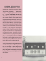
GENERAL DESCRIPTION
Conservative claims and specifications are traditional at Mclntosh.
"Rated with honesty and conservatism . . ." "impressive performance figures . . ." "Highest quality of components and construction . . ." are the words used by independent experts when writing
of Mclntosh. To assure you of highest performance every advertised
claim is individually analyzed and verified by engineers using the
most sophisticated and sensitive test instruments. Every unit is individually tested using internationally recognized test procedures. To
assure you of greatest reliability every component part is carefully
tested and evaluated by engineers before it is designed in a Mclntosh.
The MA5100 you have purchased passed more than 100 tests before
it was ready for you. Each connection, wire, resistor, capacitor is
checked and rechecked. All specifications are checked. Mclntosh
testing takes time. The extra investment in thorough testing assures
you of greater musical enjoyment. The performance of your Mclntosh MA 5100 is backed by a money back guarantee. Only Mclntosh
gives you a money back guarantee of performance. Your MA 5100
must be capable of meeting its published specifications or you get
a refund of your purchase price. Mclntosh promises performance.
We either meet our promise or you get your money back.
Your MA 5100 can be protected by a free three year factory service
contract. Take advantage of this service. Fill in the application card
found in the owner's packet. The free three year factory service
contract covers parts and labor. Under the terms of the contract all
parts and labor necessary to repair the MA5100 will be supplied
free of charge. Fill in the service contract application found in the
owner's packet now.
2
TECHNICAL DESCRIPTION
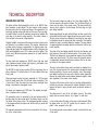
PREAMPLIFIER SECTION
The phono and tape head preamplifier circuits in the MA5100 have
three transistors in each channel. The input selector switch connects
the input jacks to the first voltage gain stage of the preamplifier. The
input stage has high voltage gain and very low noise. The next stage,
an emitter follower, acts as an impedance converter that matches the
input stage to the second voltage amplifier. The emitter follower is
direct coupled to the second voltage amplifier.
Negative feedback is used around the low level section to reduce noise
and distortion to an absolute minimum. The negative feedback also
provides precise frequency compensation for magnetic phono cartridges and tape heads. The feedback remains in effect throughout the
entire audio bandwidth, even at 20 Hz where gain is the highest. This
kind of careful Mclntosh engineering assures you of lowest distortion
performance.
The tape head input impedance is 500,000 ohms. High tape head
input impedance permits uniform high frequency performance from
typical tape transport playback heads.
The MA 5100 is ideal tor tape recording. With an input signal from a
phono cartridge of 10 millivolts, there is 1.4 volts available at the tape
output jacks.
Phono input signal overload is virtually impossible. At 1 KC the phono
input will accept greater than 125 millivolts without overloading. This
is more than 4 times the output from most phono cartridges when
playing a low distortion phonograph record.
The phono input impedance is 47,000 ohms. This matches the impedance of magnetic phono cartridges.
The preamplifier output is connected by the input selector switch to
the tape output, the tape monitor switch, the balance control, and the
first section of the volume control. This arrangement permits recording
of the program without interruption and has the ability to monitor the
recorded tape.
The loudness compensation switch is also connected to the first section of the volume control.
The tone control stages are made up of a three stage amplifier. The
first two transistors are emitter followers. The first emitter follower is
driven from the output of the volume control. The second emitter follower is direct coupled to the third stage. The third stage is a high
gain voltage amplifier.
Signals pass through the input emitter follower and then couple to the
second and third tone control stages through the tone control network.
The tone control contours are obtained by controlling the large negative feedback around the second and third transistors. This negative
feedback is used to accurately shape the response. The large amount
of negative feedback also makes possible low distortion from the tone
control amplifier.
The output of the tone shaping amplifier drives the low frequency and
high frequency filters and the second section of the volume control.
The filters are designed to remove unwanted noises such as turntable
rumble and record scratch. The filters remove the maximum amount
of objectionable material and still have a minimum effect on the musical content of the program material.
The use of a two section volume control performs two important functions. First, the input section of the volume control increases the signal
handling capability of the tone control amplifier. Use of this arrangement makes overdriving the tone control amplifier almost impossible.
Second, the output volume control assures maximum signal to noise
ratio regardless of the volume control position.
The output of the volume control is fed to a two stage voltage amplifier
that has very low noise characteristics. Negative feedback is used to
improve the signal to noise ratio and assure an absolute minimum of
distortion.
The phase switch is part of the left channel circuitry. The switch
selects from two sources that are "out of phase" to each other.
In the normal position the phase is the same in both channels. When
the phase switch is in the 180° position the left channel is "out of
phase " when compared to the right.
Out of phase program source material is easily corrected with the use
of this switch.
3
POWER AMPLIFIER SECTION
There are 9 transistors in each power amplifier. The input stage is
a pair of matched transistors arranged as an emitter coupled amplifier
with two inputs and one output. The program from the preamplifier
connects to one of the inputs, the second input is fed from the feedback loop that is around the power amplifier section. Both AC and DC
feedback are used around the power amplifier section. Noise and distortion are reduced by the use of a large quantity of feedback.
The power transistors are mounted on oversized anodized heat sinks.
The heat sinks assure that under normal operation the transistors will
operate at a low temperature. If temperatures increase due to shorted
speaker, or restricted ventilation, an automatic temperature sensing
device turns off the MA5100. The device operates automatically at a
preset temperature. The MA 5100 will turn on again when the temperature has decreased to normal operation. This additional feature gives
your MA5100 complete reliability under the most extreme operating
conditions.
To further insure reliability a special power output SENTRY MONITORING CIRCUIT prevents failure of the power output transistors due to
abnormal mismatch of the output. When your MA5100 operates normally the SENTRY MONITORING CIRCUIT has no effect on signals
passing through the power amplifier. If the power dissipation should
rise above normal operation, the SENTRY MONITORING CIRCUIT restricts the drive to the output transistors. The action of the SENTRY
MONITORING CIRCUIT is immediate for any input signal or load
combination. This arrangement assures complete circuit reliability.
Only Mclntosh gives you this degree of protection.
POWER SUPPLY SECTION
There are four separate power supply sections. One positive and one
negative high current supply is used for the output stages. One positive
and one negative low current supply is used for the preamplifier and
power amplifier input stages. All supplies are full wave and use silicon
rectifiers. Adequate filtering is used to assure an absolute minimum of
output hum. The power output stage filter capacitors have very high
capacity, which allows full power output below 20 Hz. The power transformer is generous in size and runs cool, even under heavy use.
MA 5100
4
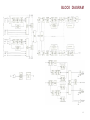
BLOCK DIAGRAM
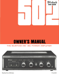
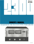
5
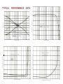
TYPICAL
PERFORMANCE
DATA
60
20
50
15
10
WATTS RMS
40
RESPONSE IN DB
5
POWER OUTPUT
0
-5
-10
-15
30
20
-20
10
20
100
1000
10000
0
20000
10
FREQUENCY IN HERTZ
PERCENT INTERMODULATION DISTORTION
PERCENT HARMONIC DISTORTION
10K
100K
.6
.5
.4
.3
.2
.1
.5
.4
,3
.2
.1
1
0
10
POWER OUTPUT IN WATTS RMS
6
1000
FREQUENCY IN HERTZ
.6
0
100
100
1
10
POWER OUTPUT EQUIVALENT WATTS RMS
100
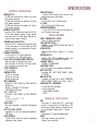
ELECTRICAL SPECIFICATIONS
POWER OUTPUT:
45 RMS watts continuous per channel into 4 ohms
both channels operating.
45 RMS watts continuous per channel into 8 ohms
both channels operating.
30 RMS watts continuous per channel into 16 ohms
both channels operating.
HARMONIC DISTORTION:
Less than 0.25% at rated power output from 20 Hz to
20 kHz, both channels operating. Typical performance is less than 0.1% at rated power. Distortion decreases as output power is reduced.
INTERMODULATION DISTORTION:
Less than 0.25% if instantaneous peak power output
is twice rated power or less per channel with both
channels operating for any combination of frequencies 20 Hz to 20 kHz.
FREQUENCY RESPONSE:
10 Hz to 25 kHz + 0, -0.5 dB at rated power.
8 Hz to 50 kHz + 0, -3.0 dB at rated power.
TOTAL NOISE (INCLUDING POWER AMPLIFER):
High Level Inputs: 75 dB below rated output
Low Level Inputs: 70 dB below 10 mV input; equivalent to less than 3 microvolts at input.
OUTPUT IMPEDANCE:
4. 8, or 16 ohms.
DAMPING FACTOR:
50 with 4 ohms load
100 with 8 ohms load
200 with 16 ohms load
INPUT IMPEDANCE:
AUXILIARY, TAPE. TUNER, and TAPE MONITOR:
250,000 ohms
PHONO 1 and PHONO 2: 47,000 ohms
TAPE HEAD: 500,000 ohms
INPUT SENSITIVITY:
AUXILIARY. TAPE, TUNER, and TAPE MONITOR:
300 mV
PHONO 1 and PHONO 2: 2 mV
TAPE HEAD: 2 mV
TAPE OUTPUT:
300 mV with rated input, 1.4 volts with 10 mV at phono
input.
LEFT PLUS RIGHT OUTPUT:
Adjustable 0 to 6 volts from generator impedance of
5,000 ohms.
BASS CONTROLS:
±18 dB at 20 Hz, with friction clutch for independent
adjustment of each channel.
SPECIFICATIONS
TREBLE CONTROLS:
± 18 dB at 20,000 Hz with f r i c t i o n clutch for independent adjustment of each channel.
HF FILTER:
Flat, or 5,000 Hz cutoff. 12 dB per octave.
LF FILTER:
Flat, or 50 Hz cutoff. 12 dB per octave.
POWER REQUIREMENTS:
117 volts. AC. 50-60 Hz. 70 watts at zero signal output, 200 watts at rated output.
SPECIAL FEATURES
COMP (COMPENSATOR) SWITCH:
RIAA or LP phono equalization.
TAPE MONITOR SWITCH:
NORMAL or Tape MONITOR indicator lamp lights in
MONITOR position.
PHASE SWITCH:
Electronic phase inverter. Normal (0°) or reverse
(180°).
SPEAKER SWITCH:
Speakers ON or OFF for headphone listening, indicator lamp lights in SPEAKER OFF position.
LOUDNESS SWITCH:
NORMAL or COMPENSATED.
HEADPHONE JACKS:
Two. for two pairs of low impedance headphones.
INPUT SELECTOR:
6 positions: AUX. TAPE. TUNER, PHONO 1, PHONO
2, TAPE HD.
MODE SELECTOR:
7 positions: L to L and R, R to L and R. STEREO REVERSE, STEREO, MONO (L + R), L + R to L, L+R to R.
SEMICONDUCTOR COMPLEMENT:
23 Silicon Rectifiers and Diodes
34 Silicon Transistors
2 Silicon Bilateral Switches
2 TRIAC
MECHANICAL SPECIFICATIONS
SIZE:
Front panel. 16 inches wide by 57/16 inches high;
chassis. 15 inches wide by 4½ inches high by 14½
inches deep, including connectors. Clearance in front
of mounting panel including knobs, 1½ inches.
WEIGHT:
25 pounds net, 41 pounds in shipping carton.
FINISH:
Front Panel: Anodized gold and black.
Chassis: Chrome and black.
7
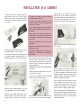
INSTALLATION IN A CABINET
To prepare the MA 5100 for installation remove the
plastic protective covering. Turn the MA 5100 upside
down so that it rests on its top on the shipping pallet.
Remove the four plastic feet fastened to the bottom
of the chassis.
If the cutout is to be located from the rear of the panel,
the following steps will help you.
On the back of the cabinet panel, scribe a vertical
centerline through the exact center of the area in which
the cutout is to be made.
Insert the screws in the center holes of the cabinet
panel ("B" holes on the template) and tighten. The
screw head should pull into the wood slightly. (Use two
¾ inch long screws for panels under ½ inch, or two 1¼
inch long screws for panels ½ inch thick and larger.)
Place the template against the back of the panel and
match the template centerline with the centerline on the
cabinet panel.
Make sure that there is at least ¼ inch clearance between the bottom of the dashed line of the cutout area
on the template and any shelf or brace below the proposed cutout.
Mark the two locating holes ("C" holes on the mounting template).
Drill the two locating holes. Be certain the drill is perpendicular to the panel.
Next place the mounting brackets, the parts bag and
the mounting template for easy accessibility.
The professional mounting design eliminates the need
for any shelf or bracket to support the MA 5100. It is
completely supported by its own mounting brackets.
Now position the template on the front of the panel by
aligning the "C" locating holes on the template with
the drill holes.
With the template in place against the cabinet panel,
mark the "A" and "B" drill holes and the four small
holes that identify corners of the cutout. Join the corner
marks with a pencil. The edge of the template can be
used as a straight edge.
IMPORTANT: DRILL THE 6 HOLES BEFORE MAKING
THE CUTOUT
Accurately drill the three holes on each side of the cutout area with a 3/16 inch drill.
With the saw on the INSIDE OF THE PENCIL LINES
carefully cut out the rectangular opening.
8
Place the template over the mounting screws. The
mounting screws should be centered in the "A" and
'B" holes on the template. The sides of the mounting
brackets should match the vertical dash lines on the
template. If necessary, loosen the screws and push the
brackets into alignment and retighten.
Insert the power cord through the opening. Carefully
slide the MA 5100 into the opening so the rails on
the bottom of the equipment slide in the track of the
mounting brackets. Continue to slide the instrument in
until the front panel is against the cabinet panel.
Position the plastic mounting template over the area
of the cabinet panel to be cut out for installation.
The design of the mounting template allows you to
position or locate the cutout from the front or rear of
the panel to which the instrument is to be mounted.
Attach the mounting brackets to the cabinet panel using four screws.
Secure the mounting strips to the rear of the cabinet
panel using two screws from the hardware package.
Secure the instrument to the mounting brackets by inserting the two knurled headed screws (from the hardware package) into the back of the MA 5100 chassis.
These screws pass through holes in the back flanges
of the mounting brackets.
IF YOU'RE IN A HURRY
INPUT SELECTOR
1 AUX ... for any device connected to the AUX
inputs on back.
TAPE ... for tape recorder with built-in electronics.
TUNER ... for FM stereo or AM/FM tuner.
PHONO 1 . . . for record player.
PHONO 2 . . . for record player.
TAPE HD ... for tape deck without electronics.
2 BASS . . . modifies low frequency sounds. Set
to your taste.
3 TREBLE . . . modifies high frequency sounds.
Set to your taste.
4 VOLUME . . . adjust to desired level.
5 BALANCE . . . make one speaker louder than
the other. Permits the adjustment of unequal
sound caused by room acoustics or program
material.
6 LOUDNESS . . . compensate for low volume
listening and still hear full frequency range.
7 HF ... FILTER in . . . reduces high frequency
noise such as record surface noise.
8 LF ... FILTER in . . . reduces low frequency
noise such as turntable rumble.
9 HEADPHONE ... to connect a set of low impedance stereo headphones.
10 POWER . . . turns system ON and OFF.
11 SPEAKER . . . turns speakers ON and OFF
for headphone listening.
MUST BE ON FOR NORMAL LISTENING.
12 PHASE . . . correct for out of phase program
source.
13 TAPE MON ... in MONITOR position hear the
tape as it is being recorded, in NORMAL hear
the program source.
MUST BE IN NORMAL POSITION TO HEAR
ALL OTHER PROGRAM SOURCES.
14 COMP . . . use RIAA with most stereo records.
15 MODE SELECTOR .... for all stereo programs,
set to STEREO position. Other positions are
for monophonic programs or for balancing
the system.
9
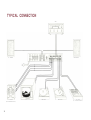
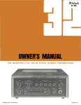
TYPICAL CONNECTION
TUNER
LEFT
TAPE
(WITH
10
RIGHT L O U D S P E A K E R
LOUDSPEAKER
RECORDER
SELF CONTAINED E L E C T R O N I C S )
TV
R E C O R D P L A Y E R 1I
RECORD
PLAYER 2
TAPE
(NO
SELF
PLAYER
CONTAINED
ELECTRONICS)
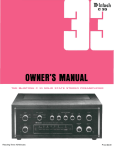
CONNECTING A LOUDSPEAKER:
The MA5100 is designed for stereo operation only. Do not connect the
MA5100 for monophonic operation. Damage to the loudspeaker may
result.
Speakers are connected at the OUTPUT barrier strips on the back
panel of the MA5100.
LEFT
RIGTH LOUDSPEAKER
LOUDSPEAKER
Connect the leads from the left loudspeaker to the LEFT OUTPUT barrier strip. Connect the leads from the right loudspeaker to the RIGHT
OUTPUT barrier strip. Use lamp cord, bell wire, or wire with similar
type of insulation to connect the speakers to the amplifier. For the
normally short distances of under 50 feet between the amplifier and
speaker, #18 wire or larger can be used. For distances over 50 feet
between the amplifier and speaker use larger wire.
LEFT OUTPUT
RIGHT OUTPUT
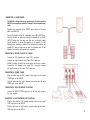
CONNECTING A RECORD PLAYER TO PHONO 1:
Connect the "left" channel to the "upper" PH 1 input jack.
Connect the "right" channel to the "lower" PH 1 input jack.
PHONO 2 position is used if two record players are used in a system.
Connect the "left" channel to the "upper" PH 2 input jack. Connect
the "right" channel to the "lower" PH 2 input jack.
CONNECTING A STEREO TUNER
Plug the cable from the "left" channel tuner output into the upper
TUNER jack on the MA5100.
Plug the cable from the "right" channel tuner output into the lower
TUNER jack on the MA5100.
CONNECTING A TAPE RECORDER TO RECORD:
Connect the MA5100 TAPE output jacks to the high level inputs on
the tape recorder.
CONNECTING A TAPE RECORDER FOR PLAYBACK:
Plug the cable from the "left" channel recorder output into the "upper"
TAPE input jack on the MA5100.
RECORD
PLAYER
1
RECORD
PLAYER
2
TAPE PLAYER
(NO SELF CONTAINED ELECTRONICS)
Plug the cable from the "right" channel recorder output into the "lower"
TAPE input jack on the MA5100.
11
CONNECTING THE TAPE PLAYER: (A tape transport without electronics.)
Plug the cable from the "left" tape head output on the tape transport
into the upper TAPE HD jack on the MA 5100.
Plug the cable from the "right" tape head output on the tape transport
into the lower TAPE HD jack on the MA 5100.
AC OUTLETS:
There are 3 black AC outlets and one red AC outlet. The power to the
black AC outlets is controlled by the front panel switch. Use these
outlets for a tuner, tape recorder, etc.
The red outlet is on at all times. Use the red outlet for a turntable or
record changer.
The turntable is protected by this arrangement. It is necessary to turn
off the turntable or record changer with its own AC switch.
GROUND CONNECTION:
A single ground post is provided. Grounds from turntables, record
changers, tape decks, etc. should be connected to this post. Do not
duplicate this ground circuit. Hum is likely to be heard if a duplicate
ground return is used. The left and right program cables from each
source should be wound or twisted in with the cables. To avoid hum,
make sure the ground wire does not make any connections to the
shields of the left and right channel cables.
BALANCING YOUR STEREO
The performance and enjoyment of a stereo system is
greatly increased when the system is properly balanced.
Three of the factors that effect proper stereo balance
are:
1 Balance of the entire system.
2 Proper phase in both channels.
3 Equal program loudness.
TO ADJUST PHASE
1 Set the MODE SELECTOR to MONO.
2 Stand about 10 feet in front of and midway between
the loudspeakers. The sound should appear to come
from directly in front of you. Have someone switch
the PHASE switch. If the sound is not directly in front
of you with the PHASE switch in the 0 NORMAL
position, reverse the leads on one loudspeaker. When
the sound comes from the mid-point between the
speakers they are in PHASE.
TO BALANCE LOUDNESS
1 Set the MODE SELECTOR to MONO.
2 Play a familiar recording.
3 Turn the BALANCE control to the 12 o'clock position.
4 While the program is playing, stand between the
two loudspeakers. Listen to see if there is a difference in loudness from either speaker. If there is a
difference, turn the control toward the speaker that
is not as loud. Do this until you find that point where
the sound is equally loud from both speakers.
12
LISTENING TO YOUR STEREO
LISTENING TO A STEREO RECORD
1 Turn the INPUT SELECTOR to PHONO 1, or PHONO 2,
whichever is connected to the record player you wish to
hear.
2 Set the MODE SELECTOR to STEREO.
3 Adjust the VOLUME control to desired volume.
LISTENING TO MONOPHONIC RECORDS
1 Turn the INPUT SELECTOR to PHONO 1, or PHONO 2,
whichever is connected to the record player you wish to
hear.
2 Turn the MODE SELECTOR to MONO.
3 Adjust the VOLUME control to the desired volume.
2 Turn the MODE SELECTOR switch to STEREO or MONO,
depending on the program on the tape.
3 Adjust the VOLUME control to the desired volume.
USING A TAPE RECORDER WITH THREE HEADS AND
SEPARATE PLAYBACK PREAMPLIFIERS
To listen to tape connect your tape recorder to the TAPE
MONITOR input on the rear of the MA5100.
1 Switch TAPE SWITCH to MONITOR.
2 Switch the MODE SELECTOR to STEREO or MONO depending on the program on the tape.
3 Adjust the VOLUME control to the desired volume.
TAPE MONITOR
LISTENING TO TAPE DECKS
1 Turn the INPUT SELECTOR to TAPE HD.
2 Turn the MODE SELECTOR to STEREO.
3 Adjust the VOLUME control to the desired volume.
LISTENING TO A STEREO TAPE RECORDER
Use the TAPE input:
1 Turn the INPUT SELECTOR to TAPE.
To monitor while recording, the tape recorder must have
separate record and playback heads. The TAPE MONITOR
permits monitoring the quality of tape recordings made while
in the process of recording. When the TAPE MONITOR switch
is in the MONITOR position it will play the sound from the
tape as it passes the playback head, a moment after it is recorded. The recording process continues as usual. When the
TAPE MONITOR switch is in the NORMAL position the program being recorded is heard.
13
USING THE FRONT PANEL CONTROLS
INPUT SELECTOR: Selects any one of six program sources:
AUX: Any high level program source requiring flat amplification, such as a television set, is connected to the input stage
of the MA5100 in the AUX position.
TAPE: Any self-contained tape machine (tape machine having
its own playback preamplifier) is connected to the high level
input stage of the MA 5100 in the TAPE position.
TUNER: AM and FM or MPX FM outputs from a stereo tuner
are connected to the high level input stage of the MA5100 in
the TUNER position.
PHONO 1: Any magnetic cartridge is connected to the low level
input stages of the MA 5100 in this position.
PHONO 2: Same as PHONO 1.
TAPE HD: A tape deck that does not contain its own playback
preamplifier is connected to the low level input stages of the
MA5100 in the TAPE HD position.
BASS CONTROLS: Use the LEFT and RIGHT BASS controls to
regulate bass loudness to the left and right speakers, respectively.
Clockwise rotation increases bass loudness; counter-clockwise
rotation decreases bass loudness. The large knob adjusts the
bass in the right channel. The small knob adjusts the bass in
the left channel.
14
TREBLE CONTROLS: Use the LEFT and RIGHT TREBLE controls
to regulate treble loudness to the left and right speakers, respectively. Clockwise rotation increases treble loudness; counterclockwise rotation increases treble loudness. The large knob
adjusts the treble in the right channel. The small knob adjusts the
treble in the left channel.
VOLUME: Use the VOLUME control to regulate the volume level
of both channels. Turning the VOLUME control clockwise increases volume level.
MODE SELECTOR: Connects the program to the loudspeaker in
the following seven ways:
L TO L & R: connects the "left" input to both loudspeakers.
R TO L & R: connects the "right" input to both loudspeakers.
STEREO REV: connects the "left" input to the "right" loudspeaker and the "right" input to the "left" loudspeaker.
STEREO: connects the "left" input to the "left" loudspeaker
and the "right" input to the "right" loudspeaker.
MONO (L + R): adds the "left" input and the "right" input and
then connects the L + R program to both amplifiers and loudspeakers.
L & R TO L: connects the "left plus right" programs to the "left"
loudspeaker only.
L + R TO R: connects the "left plus right"
programs to the "right" loudspeaker only.
COMP (COMPENSATION): Use the COMP
switch to correct for phono equalization introduced in the recording process. All current
stereo recordings use RIAA equalization.
Some early stereo and mono recordings use
LP equalization.
TAPE: The TAPE switch makes it possible to
instantaneously compare recorded material
with the signal source. Tape jacks on the
back panel accept a signal from a tape recorder with a monitor head and preamplifier.
NORMAL . . . the program source is fed
through the power amplifiers and the loudspeakers.
MONITOR . . . the signal source becomes
the recorded tape and is fed through the
power preamplifiers and loudspeakers.
When the switch is in the MONITOR position
a triangle is lighted above the switch. When
the light is on only the tape can be heard.
To listen normally the light must be off.
PHASE: Electronically reverses phase in the
left channel to correct "out of phase" program
sources.
SPEAKER: For private listening on headphones the loudspeakers can be turned off.
When the switch is in the OFF position a triangle is lighted above the switch. When the
light is on sound will not be heard from the
speakers. Only the headphones will be heard.
POWER: The POWER switch controls the AC
input power, It turns the MA5100 on and off.
The switch also controls the three black AC
outlets on the back panel.
L.F. (LOW FREQUENCY FILTER): Use the L.F.
filter switch to reduce objectionable low-frequency noise created by a turntable or record
changer and acoustically coupled feedback.
FLAT . . . filter disconnected.
FILTER ... low-frequency rumble and noise
below 50 Hz are reduced when the switch
is pushed to the FILTER position.
H.F. (HIGH-FREQUENCY FILTER): Use the
H.F. filter switch to reduce objectionable highfrequency noise such as record scratch.
FLAT . . . filter disconnected.
FILTER . . . rolls off response sharply at
5 kHz.
LOUD: When the volume is reduced, the music
will seem to lose much of its bass and some
of its treble. This effect is due to the sensitivity characteristic of human hearing. The
response of the human ear to bass and treble
pitch decreases more rapidly than its response to notes centered in the mid-tonal
range. The LOUD control automatically provides the correct amount of bass and treble
boost required to compensate for this change
in response of the human ear at low-loudness
levels. When the "LOUD" switch is moved to
the IN position, it converts the volume control
to a loudness compensated control. Use the
LOUD IN to listen at low volume and still hear
full-frequency range.
BALANCE CONTROL: Use the BALANCE control to adjust both channels to equal loudness. The volume of each speaker system
relative to the other can be varied, at the
same time their combined volume level is
maintained.
LEFT . . . turning the control to the left accents the left channel by reducing the right
channel output.
RIGHT . . , turning the control to the right
accents the right channel by reducing the
left channel output.
MA51OO
15
GUARANTEE
Mclntosh Laboratory Incorporated guarantees this instrument to be capable
of performance as advertised. We also guarantee the mechanical and electrical workmanship and components to be free of defects for a period of 90
days from date of purchase. If such defects occur, Mclntosh Laboratory or
one of its authorized agencies will repair the defect at no cost to the purchaser. This guarantee does not extend to components damaged by improper
use nor does it extend to transportation to and from the factory or service
agency.
THREE YEAR FACTORY SERVICE CONTRACT
An application for a FREE THREE YEAR FACTORY SERVICE CONTRACT is
included with this manual. The terms of the contract are:
For Three Years from date of purchase
1. Mclntosh will provide all parts, materials and labor needed to return
the measured performance of the instrument to the original factory
specifications free of any charge. The SERVICE CONTRACT does not
cover any shipping costs to and from the authorized service agency
or the factory.
2. Any Mclntosh authorized service agency will repair all Mclntosh Instruments at normal service rates. To receive the free service under the
terms of the SERVICE CONTRACT, the SERVICE CONTRACT CERTIFICATE must accompany the instrument when taken to the service
agency.
3. Always have service done by a Mclntosh authorized service agency.
If the instrument is modified or damaged as a result of unauthorized
repair the SERVICE CONTRACT will be cancelled.
4. The SERVICE CONTRACT is issued to you as the original purchaser.
To protect you from misrepresentation this contract cannot be transferred to a second owner.
5. The SERVICE CONTRACT is given to the purchasers who live in the
50 United States or Canada only.
6. For your protection Mclntosh selects its dealers carefully. The requirements are very strict. Only one dealer in seven applicants qualifies for
a Mclntosh franchise. To receive the SERVICE CONTRACT your purchase must be made from a Mclntosh franchised dealer.
7. Your completely filled in application for a SERVICE CONTRACT must
be postmarked within 30 days of the date of purchase of the instrument.
8. To receive the SERVICE CONTRACT all information on the application must be filled in. The SERVICE CONTRACT will be issued when
the completely filled in application is received at Mclntosh Laboratory
Incorporated in Binghamton, New York. If the application is not received at Mclntosh Laboratory, only the service offered under the 90day guarantee will apply.
TAKE ADVANTAGE
3
OF
YEARS OF FREE FACTORY SERVICE
FILL IN THE APPLICATION NOW
Your MA5100 stereo preamplifier/power
amplifier will give you many years of
pleasant and satisfactory performance. If
you have any questions concerning operation
or maintenance please contact the dealer
from whom you purchased this instrument
or: —
CUSTOMER SERVICE
Mclntosh Laboratory Inc.
2 Chambers Street
Binghamton, New York 13903
Our telephone number is 607-723-3512
16
MclNTOSH LABORATORY INC.
2 CHAMBERS ST., BINGHAMTON, N. Y. 13903
607-723-3512
Design subject to change without notice.
Printed in U.S.A.
038-329
BE032003