1
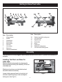
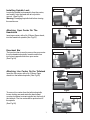
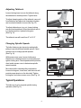
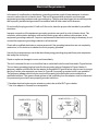
Mini Lathe
Owner’s Manual
Model: 70-100
Record the serial number and date of purchase
in your manual for future reference.
Serial number:
Date of purchase:
For more information:
www.rikontools.com
Part # 70-100M2
or
[email protected]
For Parts or Questions:
[email protected] or 877-884-5167
Safety Warning
IMPORTANT! Safety is the single most important consideration in the operation of this equipment. The following
instructions must be followed at all times.
There are certain applications for which this tool was designed. We strongly recommend that this tool not be modified
and/or used for any other application other than that for which it was designed. If you have any questions about its
application, do not use the tool until you have contacted us and we have advised you.
General Safety Warnings
KNOW YOUR POWER TOOL. Read the owner’s manual carefully. Learn the tool’s applications, work
capabilities, and its specific potential hazards.
ALWAYS GROUND ALL TOOLS.
If your tool is equipped with a three-pronged plug, you must plug it into a three-hole electric
receptacle. If you use an adapter to accommodate a two-pronged receptacle, you must attach the
adapter plug to a known ground. Never remove the third prong of the plug.
ALWAYS AVOID DANGEROUS ENVIRONMENTS.
Never use power tools in damp or wet locations. Keep your work area well lighted and clear of clutter.
ALWAYS REMOVE THE ADJUSTING KEYS AND WRENCHES FROM TOOLS AFTER USE.
Form the habit of checking to see that keys and adjusting wrenches are removed from the tool before
turning it on.
ALWAYS KEEP YOUR WORK AREA CLEAN. Cluttered areas and benches invite accidents.
ALWAYS KEEP VISITORS AWAY FROM RUNNING MACHINES.
All visitors should be kept a safe distance from the work area.
ALWAYS MAKE THE WORKSHOP CHILDPROOF.
Childproof with padlocks, master switches, or by removing starter keys.
NEVER OPERATE A TOOL WHILE UNDER THE INFLUENCE OF DRUGS,
MEDICATION, OR ALCOHOL.
ALWAYS WEAR PROPER APPAREL.
Never wear loose clothing or jewelry that might get caught in moving parts. Rubber-soled footwear is
recommended for the best footing.
ALWAYS USE SAFETY GLASSES AND WEAR HEARING PROTECTION.
Also use a face or dust mask if the cutting operation is dusty.
NEVER OVERREACH.
Keep your proper footing and balance at all times.
NEVER STAND ON TOOLS.
Serious injury could occur if the tool is tipped or if the cutting tool is accidentally contacted.
2
ALWAYS DISCONNECT TOOLS.
Disconnect tools before servicing and when changing accessories such as blades, bits, and cutters.
ALWAYS AVOID ACCIDENTAL STARTING.
Make sure switch is in “OFF” position before plugging in cord.
NEVER LEAVE TOOLS RUNNING UNATTENDED.
ALWAYS CHECK FOR DAMAGED PARTS.
Before initial or continual use of the tool, a guard or other part that is damaged should be checked to
assure that it will operate properly and perform its intended function. Check for alignment of moving
parts, binding of moving parts, breakage of parts, mounting, and any other conditions that may affect
its operation. A guard or other damaged parts should immediately be properly repaired or replaced.
Special Safety Rules For Lathes
1. Do not operate this machine until you have read all of the following instructions.
2. Do not attempt to operate this machine until it is completely assembled.
3. Do not turn ON this machine if any pieces are missing.
4. If you are not familiar with the operation of the machine, obtain assistance from a qualified person.
5. It is highly recommended that this machine be firmly mounted to a flat and secure work surface.
6. Always wear protective eyewear prior to operating this machine.
7. Do not operate this machine if you are under the influence of drugs and/or alcohol.
8. Remove all jewelry prior to operating this machine.
9. Do not wear any gloves while operating this machine.
10. Always make sure the power switch is in the OFF position prior to plugging in the machine.
11. Always make sure the power switch is in the OFF position when doing any assembly or setup
operation.
12. Always turn the power switch to the OFF position and let the work piece come to a complete stop
prior to removal.
13. Use only sharp lathe tools.
14. The use of any accessories or attachments not recommended may cause injury to you and
damage your machine.
15. This machine must be properly grounded.
16. When turning between centers, make sure headstock and tailstock are snug against work piece.
17. When face plate turning, rough-cut work piece close to the finished shape before screwing to face
plate.
18. Never jam tools into work piece or take too big a cut.
19. Do not operate this machine without following all these instructions.
20. Keep these instructions for future reference.
SAVE THESE INSTRUCTIONS.
Refer to them often.
3
Table of Contents
Safety Warnings.....................................................................................................................................................2
Lathe Safety Rules................................................................................................................................ ............... 3
Specifications.........................................................................................................................................................4
Unpacking and Contents..................................................................................................................................... .5
Getting to Know Your Lathe...................................................................................................................................6
Assembly................................................................................................................................................................ 6
Installing the Tool Rest and Base........................................................................................................................ .6
Installing Spindle Lock...........................................................................................................................................7
Attaching the Spur Center.....................................................................................................................................7
Attaching the Live Center......................................................................................................................................7
Installing the Faceplate..........................................................................................................................................8
Installing the Tool Holder........................................................................................................................................8
Securing the Lathe to a Work Surface or Stand..................................................................................................8
Adjustments............................................................................................................................................................8
Adjusting the Tool Rest..........................................................................................................................................8
Adjusting the Tailstock...........................................................................................................................................9
Changing Spindle Speeds....................................................................................................................................9
Typical Operations.................................................................................................................................................9
Indexing /Spindle Lock........................................................................................................................................10
Maintenance.........................................................................................................................................................10
Electrical Requirements...............................................................................................................................................11
Wiring Diagram......................................................................................................................................12
Troubleshooting....................................................................................................................................................13
Explosion Diagram..............................................................................................................................................14
Parts List...............................................................................................................................................................15
Warranty.................................................................................................................................................................16
Notes......................................................................................................................................................................17
Specifications
Model Number
Swing Over Bed
Swing Over Tool Rest Base
Working Distance Between Centers
Motor
Speeds
Speed Ranges
Spindle Nose in x TPI
Headstock Taper
Tailstock Taper
Hole Through Spindle
Ram Travel
Overall Dimensions
Net Weight
70-100
12”
9-1/2”
16”
1/2HP, 1Ph, 115V only
6
430,810,1230,1810,2670,3900 RPM
1”x 8
MT2
MT2
3/8”
2-1/2”
31-3/4”(L)x18”(W)x11-1/2”(H)
88.5 lbs
4
Contents of Package
Unpacking and Checking Contents
Unpack your lathe from its carton and check to see that you have all of the following items. Do not turn
your machine ON if any of these items are missing. You may cause injury to yourself or damage to your
machine.
Item
Description
Q’ty
A
Lathe.........................................................1
B
Knokout Bar..............................................1
C
Wrench.....................................................1
D
Tool Rest....................................................1
E
Live Center................................................1
F
Spur Center...............................................1
G
Spindle Lock Assembly..............................1
H
Knokout Bar for Live Center pointer..........1
I
Tool Holder................................................1
J
Pan head screw.......................................2
K
Manual/Warranty Card................................1
Tools Required for Assembly
Item
Description
Phillips Screwdriver
Adjustable Wrench
Unpacking and Clean-up
1. Carefully finish removing all contents from shipping cartons. Compare contents of the shipping
cartons with the list of contents above. Place parts on a protected surface.
2. Report any shipping damage to your local distributor.
3. Clean all rust protected surfaces with kerosene or diesel oil. Do not use; gasoline, paint thinner,
mineral spirits, etc. These may damage painted surfaces.
4. Set packing material and shipping cartons to the side. Do not discard until machine has been
set up and is running properly.
5
Getting to Know Your Lathe
3
2
4
5 6 7 8
10
9
11
12
1
9
17
16
15
14
13
Item
Description
Item
Description
1
2
3
4
5
6
7
8
9
Lifting handle
Switch
Handwheel
Face plate
Spur center
Tool rest
Live center
Tail stock
Tailstock handwheel
10
11
12
13
14
15
16
17
Tailstock spindle locking arm
Tool rest base
Spindle lock
Tool holder
Motor
Lathe bed
Tailstock locking lever
Tool rest seat locking lever
Assembly
The machine must not be plugged in and the power switch must be in the OFF position until assembly is
complete.
Installing Tool Rest and Base On
Lathe Bed
Tool rest
Remove the tailstock assembly by releasing the
locking handle and sliding the assembly off the end
of the lathe bed.
Tool rest base
Locking arm
Slide the tool rest base onto the lathe bed and
reinstall the tailstock assembly.
Loosen locking arm and insert tool rest into tool
rest base, adjust height up or down and tighten
locking arm. (See Fig.01)
Fig.01
6
Spindle lock
Installing Spindle Lock
Locate the spindle lock assembly from the carton,
and install it onto the head with an adjustable
wrench. (See Fig.02)
Warning: Disengage spindle lock before turning
the machine on.
Fig.02
Attaching Spur Center On The
Headstock
Headstock spindle
Insert spur center, with a No. 2 Morse Taper shank,
into the headstock spindle.(See Fig.03)
Spur center
Fig.03
Knockout Bar
The knockout bar is used to remove the spur center
from the headstock spindle. Insert knockout bar
into hole at opposite side from spur center.
(See Fig.04)
Knockout bar
Fig.04
Attaching Live Center On the Tailstock
Tailstock spindle
Insert the live center, with a No. 2 Morse Taper
shank into the tailstock spindle. (See Fig.05)
Live center
Fig.05
To remove live center from the tailstock spindle,
loosen locking arm and rotate the hand wheel
counter clockwise to retract spindle into the body of
the tailstock. The live center will be pushed out of
the spindle.
(See Fig.06)
Knockout bar
7
Fig.06
Installing The Faceplate to the
Headstock
Thread the faceplate clockwise on to the
headstock spindle. Next, engage the spindle lock
and stop the spindle from turning, and tighten
faceplate with supplied wrench. (See Fig.07)
Spindle lock
Faceplate
Warning: Disengage spindle lock before turning
the machine on.
Fig.07
Installing Tool Holder On the Lathe
Bed
Tool holder
Located the tool holder from the carton, and install
it onto the lathe bed with two pan head screws.
(See Fig.08)
Pan head screw
Fig.08
Secure Lathe to a Solid Work Surface
The lathe must be attached to a solid work surface
or stand. Four mounting holes are easily
accessible at the base of the lathe. (See Fig.09)
Mounting holes
Fig.09
Adjustments and Operations
Adjusting the Tool Rest
The tool rest base can be easily moved along the
lathe bed. Loosen locking lever counter clockwise,
slide tool rest base to new position, and tighten
locking lever clockwise.
To adjust the height of the tool rest, loosen locking
arm, raise or lower tool rest, tighten locking arm.
(See Fig.10)
Note: Position the tool rest as close to the work
piece as possible. It should be 1/8” above the
centerline of the workpiece.
To adjust clamping action of the tool rest base,
remove base and adjust nut clockwise to tighten
and counterclockwise to loosen.(See Fig.11)
8
Tool rest
Tool rest base
Locking arm
Locking lever
Fig.10
Tool rest base
Locking lever
Locking arm
Fig.11
Adjusting Tailstock
Loosen locking lever to move the tailstock along
the lathe bed to desired position. Tighten lever.
To adjust clamping action of the tailstock, remove it
from lathe bed and adjust nut clockwise to tighten
and counterclockwise to loosen.(See Fig.12)
Nut
To adjust tailstock arm in or out, loosen locking
arm and turn handwheel. When the tailstock arm is
in a desired position, tighten locking arm.
(See Fig.13)
Fig.12
Handwheel
Tailstock arm
The tailstock arm will travel from 0” to 2-1/2”
Locking arm
Changing Spindle Speeds
Locking lever
The lathe features a six step motor and spindle
pulleys to provide different spindle speeds. Open
access cover to change spindle speeds.
(See Fig.14)
Fig.13
With access cover open, loosen locking arm.
Raise lever to release tension on motor pulley and
tighten locking arm. Check speed and belt position
chart inside access cover to determine spindle
speed required.
Access cover
Locking arm
Move drive belt to desired pulley combination.
Loosen locking arm, lower lever, and the motor will
provide proper tension on the drive belt. Tighten
locking arm and close access cover. (See Fig.14)
Belt position Chart
Tension lever
Fig.14
Typical Operations
The lathe is set up for a typical spindle turning
operation.(See Fig.15)
Fig.15
9
The lathe can be set up for a faceplate turning
operation. The work piece should be “rough
cut” as close as possible to finished shape
before mounting. (See Fig.16)
Indexing/Spindle Lock
The dual purpose indexing/spindle lock is
positioned on the top of the headstock for ease of
use. The headstock indexing feature has 12 equally
spaced positions. The spring loaded locking pin
assembly is engaged by turning the knob a half turn
allowing it to drop into the desired position. To
disengage, lift the lock knob up and turn a half turn
either direction. (See Fig.17 & Fig.18)
Fig.16
The 12 position indexing feature allows accurate
pattern work on projects such as straight fluting,
grooving, drilling, lay out and more. This feature
also allows the user to lock the spindle for
removing face plates, chucks and other
accessories without needing two tools.
Fig.17
To use the spindle lock, disengage the locking pin
by lifting up and rotating a half turn. The pin will
engage in the closest pin available. Once locked
an accessory such as a face plate can be removed
with the wrench supplied.
Fig.18
Maintenance
CAUTION! BEFORE CLEANING OR CARRYING OUT MAINTENANCE WORK, DISCONNECT
THE MACHINE FROM THE POWER SOURCE (WALL SOCKET). NEVER USE WATER OR
OTHER LIQUIDS TO CLEAN THE MACHINE. USE A BRUSH. REGULAR MAINTENANCE OF THE
MACHINE WILL PREVENT UNNECESSARY PROBLEMS.
Keep the lathe bed casting clean and lubricated.
Keep the outside of the machine clean to ensure accurate operation of all moving parts and prevent
excessive wear.
Keep the ventilation slots of the motor clean to prevent it from overheating.
Remove all saw dust and chips from the lathe after each use.
10
Electrical Requirements
In the event of a malfunction or breakdown, grounding provides a path of least resistance for electric
current to reduce the risk of electric shock. This tool is equipped with an electric cord having an
equipment-grounding conductor and a grounding plug. The plug must be plugged into a matching outlet
that is properly installed and grounded in accordance with all local codes and ordinances.
Do not modify the plug provided. If it will not fit the outlet, have the proper outlet installed by a qualified
electrician.
Improper connection of the equipment-grounding conductor can result in a risk of electric shock. The
conductor, with insulation having an outer surface that is green with or without yellow stripes, is the
equipment-grounding conductor. If repair or replacement of the electric cord or plug is necessary, do not
connect the equipment-grounding conductor to a live terminal.
Check with a qualified electrician or service personnel if the grounding instructions are not completely
understood, or if in doubt as to whether the tool is properly grounded.
Use only three wire extension cords that have three-prong grounding plugs and three-pole receptacles
that accept the tool’s plug.*
Repair or replace a damaged or worn cord immediately.
This tool is intended for use on a circuit that has an outlet that looks the one illustrated in Figure A below.
The tool has a grounding plug that looks like the grounding plug as illustrated in Figure A below. A
temporary adapter, which locks like the adapter as illustrated in Figure B below, may be used to connect
this plug to a two-pole receptacle, as shown in Figure B if a properly grounded outlet is not available.**
The temporary adapter should only be used until a properly grounded outlet can be installed by a
qualified electrician. The green colored rigid ear or tab, extending from the adapter, must be connected
to a permanent ground such as a properly grounded outlet box.
* Canadian electrical codes require extension cords to be certified SJT type or better.
** Use of an adapter in Canada is not acceptable.
11
Wiring Diagram
WARNING:This machine must be grounded.
Replacement of the power supply cable should only be done by a qualified electrician.
Switch
Plug
Motor
12
13
Troubleshooting
Explosion Diagram
14
Parts List
KEY No. Description
70-100 1
70-100 2
70-100 3
70-100 4
70-100 5
70-100 6
70-100 7
70-100 8
Part No.
Center point
1-JL93010001
Spur center
1-JL93010002
Faceplate
1-JL93010003-001Y
Spindle shaft
1-JL93010004
Bearing 6005-2Z
1-BRG6005-2RSV2
Ring retaining 47mm
1-CLP47GB893D1B
Indexing gear
1-JL93010006
Hex socket set screw
1-M6X8GB80B
M6x8
70-100 9 Spindle head
1-JL93010007-050W
70-100 9A Warning label
1-RK93081006
70-100 10 Wave washer 47mm
1-JL93010008
70-100 11 Ring retaining 25mm
1-CLP25GB894D1B
70-100 12 Poly-v-belt
1-JL93010009
70-100 13 Hex socket set screw
1-M6X12GB80B
M6x12
70-100 14 Spindle pulley
1-JL93010010
70-100 15 Ring retaining 19mm
1-CLP19GB894D1B
70-100 16 Handwheel
1-JL93010011
70-100 17 Spindle lock knob
1-0804011-01001S
70-100 18 Spindle lock tube
1-JL93010013
70-100 19 Spindle lock shaft
1-JL93010015
70-100 19A Spindle lock spring
1-JL93010014
70-100 19BPin roll 3x16
1-PIN3X16GB879D1B
70-100 21 Rounded insert
1-JL93010016
70-100 22 Power cable plate
1-JL93040001
70-100 23 Strain relief
1-403106
70-100 24 Pan head screw
1-M5X12GB818B
M5x12
70-100 24A Locking washer M5
1-WSH5GB862D2B
70-100 25 Box switch
1-JL93040002-001S
70-100 26 Switch plate
1-JL93040003
70-100 27 Lock switch
1-J-9301B
70-100 28 Pan head screw
1-M6X10GB818B
M6x10
70-100 30 Pan head tapping screw 1-ST4D2X25GB845B
ST4.2x22
70-100 31 Pan head screw
1-M4X10GB818B
M4x10
70-100 32 Locking washer M4
1-WSH4GB862D1B
70-100 33 Hex. Nut M4
1-M4GB6170Z
70-100 34 Close-end connector
1-JL93040008
70-100 35 Hex. Socket head screw 1-M6X35GB70B
M6x35
70-100 36 Spring washer 6mm
1-WSH6GB93B
70-100 37 Washer 6mm
1-WSH6GB97D1Z
70-100 40 Bed
1-JL93010021-049W
70-100 40A Tool holder
1-JL93010017-001S
70-100 40BWasher 6mm
1-WSH6 GB97D1B
70-100 40CPan head screw
1-M6X16GB818B
M6x16
70-100 40DName label
1-RK93081002
70-100 40EWarning label
1-RK93081005
70-100 41 Cable tube
1-JL93040004-001S
70-100 42 Fence
1-JL93010019-001Z
70-100 44 Pan head screw
1-M5X10GB818B
M5x10
70-100 45 8" tool holder
1-JL93020001-001G
70-100 46 Tool holder seat
1-JL93020002-105L
70-100 47 Lock arm
1-JL930210000A
70-100 48 Lock lever
1-JL93020003
70-100 50 Collar
1-JL93020004
KEY No. Description
70-100 51
70-100 52
70-100 53
70-100 54
70-100 55
70-100 56
70-100 58
70-100 59
70-100 61
70-100 62
70-100 63
Part No.
Ring retaining 12mm
1-CLP12GB894D1B
Clamp bolt cover
1-JL93020005
Position plate
1-JL93030012
Lock nut M10
1-M10GB889Z
Live center
1-JL93031000
Axle sleeve
1-JL93030001
Bolt
1-JL93030003
Ring retaining
1-CLP12GB896B
Tail stock
1-JL93030005-050W
Handwheel
1-JL90030006
Hex. Socket set screw 1-M6X12GB80B
M6x12
70-100 64 Handwheel handle
1-JL93030007
70-100 65 Screw
1-JL93030009
70-100 66 Lock arm
1-JL93021000
70-100 67 Lock lever
1-JL93030009
70-100 68 Hex. Socket set screw 1-M5X8GB77B
M5x8
70-100 69 Scr shaft
1-JL93030010
70-100 70 Spring
1-JL93030011
70-100 71 Clamp plate
1-JL93030012
70-100 72 Lock nut M10
1-M10GB889Z
70-100 73 Ring retaining 10mm
1-CLP10GB894D1B
70-100 74 Lifting handle
1-JL93050001
70-100 75 Lifting handle clamping 1-JL93050002
70-100 75A Pan head screw
1-M5X10GB818B
M5x10
70-100 76 Hinge
1-JL93050003
70-100 77 Lock washer M4
1-WSH4GB862D1B
70-100 78 Pan head screw
1-M4X10GB818B
M4x10
70-100 79 Motor pulley cover
1-JL93050004-001Z
70-100 80 Hex. Nut M4
1-M4GB6170B
70-100 81 Access cover
1-JL93050005-001S
70-100 82 Warning label
1-RK93081004
70-100 83 Lock housing bracket
1-JL93050006
70-100 84 Lock housing
1-JL93050007
70-100 85 Belt position chart
1-RK93081003
70-100 90 Motor
1-H3612624
70-100 91 Motor label
1-RK93081009
70-100 92 Belt tension handle
1-JL93041000
70-100 93 Belt tension handle cover1-JL93040005
70-100 94 Locking arm
1-JL93021000B
70-100 95 Special washer 8mm
1-JL93040007
70-100 97 Spring washer 6mm
1-WSH6GB93B
70-100 98 Hex. Socket head screw 1-M6X15GB70B
M6x15
70-100 99 Motor pulley
1-JL93040006
70-100 100 Hex. Socket set screw 1-M6X12GB78B
M6x12
70-100 101 Brand label
1-RK93081001
70-100 102 Rivet M2.5x5
1-RVT2D5X5GB827C
70-100 103 Power cable
1-U23182300-472
70-100 104 Knokout bar
1-JL93070002
70-100 104A Knokout bar
1-JL93070001
70-100 105 Wrench
1-JL93070003
70-100 M2 Manual
1-RK93082006
15
Warranty
5-Year Limited Warranty
RIKON Power Tools, Inc. (“Seller”) warrants to only the original retail consumer/purchaser of our
products that each product be free from defects in materials and workmanship for a period of five
(5) years from the date the product was purchased at retail. This warranty may not be transferred.
This warranty does not apply to defects due directly or indirectly to misuse, abuse, negligence,
accidents, repairs, alterations, lack of maintenance or normal wear and tear. Under no
circumstances will Seller be liable for incidental or consequential damages resulting from
defective products. All other warranties, expressed or implied, whether of merchantability,
. This warranty does not cover
products used for commercial, industrial or educational purposes.
This limited warranty does not apply to accessory items such as blades, drill bits, sanding discs or
belts and other related items.
Seller shall in no event be liable for death, injuries to persons or property, or for incidental,
contingent, special, or consequential damages arising from the use of our products.
To take advantage of this warranty proof of purchase documentation, which includes date of
purchase and an explanation of the complaint, must be provided.
The Seller reserves the right to effect at any time, without prior notice, those alterations to parts,
.
To take advantage of this warranty, please fill out the enclosed warranty card and send it to:
RIKON Warranty
16 Progress Rd.
Billerica, MA. 01821
The card must be entirely completed in order for it to be valid. If you have any questions
please contact us at 877-884-5167 or [email protected].
16
Notes:
17
For more information:
16 Progress Rd.
Billerica, MA. 01821
877-884-5167 / 978-528-5380
[email protected]
www.rikontools.com
Copyright RIKON Power Tools, Inc. 2006
Printed in China 5/06