1
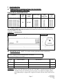
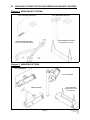
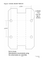
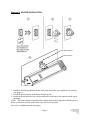
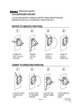
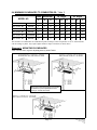
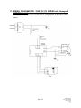
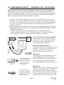
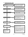
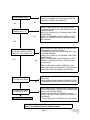
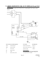
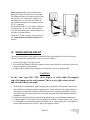
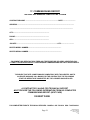
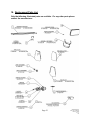
INSTALLATION /OWNER’S MANUAL
2300
&
IO-210
SERIES
HIGH EFFICIENCY
INFRA-RED PATIO HEATER
FOR OUTDOOR AND NON RESIDENTIAL
INDOOR SPACES
FOR YOUR SAFETY:
FIELD CONVERTIBILITY:
Do not store or use gasoline or other flammable
vapours and liquids in the vicinity of this or any
other appliance.
If you smell Gas:
>Shut off gas to the appliance
>Extinguish any open flames
>Don’t touch electrical switches
>Call your Gas supplier immediately
“The conversion shall be carried out in accordance
with the requirements of the authorities having
jurisdiction and in accordance with the
requirements of the B149.1 ( latest edition)
INSTALLATION CODE” in Canada, and the
ANSI Z223.1 (latest edition) in the U.S.A.
MEMBER OF
GP-M230-BX-06A
2300 / IO 210 Manual
RD: Sept, 2005
R.L. 6
KH
NOTICE:
The manufacturer reserves the right to make changes to equipment and specifications without
obligation or notification.
This publication, or parts thereof, may not be reproduced in any form, without prior written consent
from the manufacturer
Unauthorized use or distribution of this publication is strictly prohibited.
Schwank Inc.
5285 Bradco Boulevard
Mississauga, Ontario
L4W 2A6
Phone: 905 -712-4766
Fax: 905- 712-8336
e-mail: [email protected]
1-866-361-0417
Infrasave Inc.
5285 Bradco Boulevard
Mississauga, Ontario
L4W 2A6
Phone: 1- 866-INFRASV (463-7278)
Fax: 905- 712-8336
e-mail: [email protected]
PO Box 988, 2 Schwank Way
Waynesboro, Georgia,
USA 30830
Phone: (706) 554-6191
Fax: (706) 554 9390
Infrasave Inc.
Waynesboro, Georgia,
USA 30830
Customer Service:
Phone: (706) 554-6191
Fax: (706) 554 9390
e-mail: [email protected]
1-877-446-3727
http://www.schwankheaters.com
Technical support:
1-877-446-3727
e-mail: [email protected]
GP-M230-BX-06A
2300 / IO 210 Manual
RD: Sept, 2005
R.L. 6
KH
2300 /IO-210
SERIES
INFRA-RED PORTABLE PATIO HEATER
FOR OUTDOOR AND NON RESIDENTIAL
INDOOR SPACES
TABLE OF CONTENTS
TOPIC
PAGE NUMBER
1. GENERAL.............................................. 1
2. INSTALLATION REQUIREMENTS ... 1
2.1 MOUNTING CLEARANCES ......... 1
2.2 HEATER MOUNTING.................... 1
2.3 GAS SUPPLY INSTALLATION .... 1
2.4 GAS PRESSURE ............................. 2
3. INSTALLATION PROCEDURES ........ 2
4. LIGHTING INSTRUCTIONS .............. 3
5. SHUT DOWN INSTRUCTIONS .......... 3
6. STAINLESS STEEL PARTS................. 3
7. SERVICING GUIDE ............................. 3
8. CONFIGURATION ............................... 5
8.1 DIMENSIONS.................................. 5
8.2 DELUXE HANGING KIT ............... 5
8.3 MOUNTING OPTIONS................... 6
8.4 MINIMUM CLEARANCES TO
COMBUSTABLES ........................ 11
8.5 SUGGESTED MOUNTING
DISTANCES .................................. 12
TOPIC
PAGE NUMBER
9. ELECTRICAL REQUIREMENTS ...... 13
9.1 REMOTE CONTROL .................... 13
10. SEQUENCE OF OPERATIONHONEYWELL S87C DSI .................... 13
11. WIRING DIAGRAM– HONEYWELL
S87C DSI .............................................. 14
12. FLAME SENSING CIRCUIT HONEYWELL S87C DSI .................... 15
13. TROUBLESHOOTING GUIDE .......... 16
14. WIRING DIAGRAM- FENWAL 35-60
DSI ........................................................ 18
15. SEQUENCE OF OPERATIONFENWAL 35-60 DSI ............................ 19
16. SPARK IGNITION CIRCUIT ............. 20
17. COMMISSIONING REPORT ............. 21
18. REPLACEMENT PARTS LIST...........23
19. LIMITED WARRANTY...................... 24
GP-M230-BX-06A
2300 / IO 210 Manual
RD: Sept, 2005
R.L. 6
KH
IMPORTANT NOTICES AND WARNINGS:
Important notice To Installer:
Installation and repairs should be done by a qualified service person.
This Operation & Instruction manual is not to be removed from the site. It
MUST be given in its entirety to the consumer and retained for future reference.
Warning
•
Improper Installation, adjustment, alteration, service or maintenance can
cause injury or property damage. READ the installation, operating and
maintenance instructions thoroughly before installing or servicing this
equipment. It is imperative that control compartment, burners and
circulating air passageways be kept clean and unobstructed.
Warning
•
Due to the effects of radiant heat upon certain materials it is not recommended to store or place items that could be damaged or distorted, directly
under this heater....i.e. Non combustible patio furniture etc.
•
Children and Adults should be alerted to the hazards of high surface temperatures and should be careful to avoid burns or clothing ignition.
Young children should be carefully supervised when in the area of a heater.
Clothing or other flammable materials should not be hung from, or placed
near to the heater.
•
•
Warning
Keep this appliance area free from combustible materials, gasoline and other
flammable vapours and liquids.
GP-M230-BX-06A
2300 / IO 210 Manual
RD: Sept, 2005
R.L. 6
KH
1. GENERAL
The gas fired infra-red combined intensity heaters are suitable to be installed for heating of outdoor and non residential indoor spaces. These installation instructions are intended for the Series 2300 / IO 210 Heaters.
All installations must conform to the following:, all local and national code requirements including the current CAN/CGA-B149.1 installation code for gas burning appliances and equipment as well as the Canadian Electrical Code PART 1 CSAC22.1 (latest edition) must be observed. All installations in the U.S.A. must conform to local and national code requirements
including, National Fuel Gas code ANSI Z223.1, and the National Electrical Code ANSI/NFPA
No 70 (latest edition). Due to ever changing standards and requirements, revision to equipment
and installation procedures may be necessary. In case of discrepancies, the latest installation
manual will take priority.
2. INSTALLATION REQUIREMENTS
2.1 MOUNTING CLEARANCES
Series 2300 / IO 210 Heaters must be mounted with minimum clearances as shown in Section
8.4. It should also be located with respect to building construction and equipment so as to provide sufficient clearance and accessibility for servicing and cleaning of burners and ignition
control. Minimum mounting height is to be no less than 96”. Do not store or place anything directly underneath heater
2.2 HEATER MOUNTING
Series 2300 / IO 210 Heaters are approved for both horizontal and angle mounting. When angle
mounting, the short axis may be rotated to a maximum of 45°; however this may direct a large
portion of infrared heat above the heads of seated occupants in many applications.
Schwank recommends a 30° mounting angle in most applications. Refer to Diagram 8. Improper angle mounting can result in damage to the heater or unsafe operation, and will void
warranty.
IMPORTANT: For either horizontal or angle mounting, the long axis of the heater must be
level. Use only non-combustible mounting hardware. Diagram 2 on Page 5 illustrates typical
suspension hardware that may be used., and provided by Schwank as an optional component.
2.3 GAS SUPPLY LINE INSTALLATION
•
•
•
•
•
•
All piping must be installed according to local codes.
An approved flexible connector between the heater and gas piping must be installed. The
same is available as an option from Schwank.
A drip-pocket at the inlet connection must be provided.
On propane-fired units, a main line filter is recommended.
Piping joint compounds must be resistant to the action of liquefied petroleum gases.
All piping joints should be tested for leaks with a soap and water solution.
Page 1
GP-M230-BX-06A
2300 / IO 210 Manual
RD: Sept, 2005
R.L. 6
KH
2.4 GAS PRESSURE
The maximum supply pressure must be limited to 14" w.c. (0.5 psi). If the line pressure is
above 14" w.c., then a separate pressure reducing regulator must be installed. The minimum
pressure at the inlet to the heater regulator must be equal to or greater than 6.0" w.c. for natural
gas and 11.0" w.c. for propane gas.
CAUTION:
DO NOT INSTALL ANY GAS PIPING IN HEAT ZONES.
Proper manifold pressure will be maintained when the main burner is operating under the following supply pressure:
LINE PRESSURE w.c.”
MANIFOLD PRESSURE w.c.”
MINIMUM
MAXIMUM
AT GAS VALVE TEST POINT
NATURAL GAS
6.0
14.0
5.0
PROPANE GAS
11.0
14.0
10.0
Natural Gas: models are orificed for 1000 BTU/CU.FT.
Propane Gas: models are orificed for 2500 BTU/CU.FT.
3. INSTALLATION PROCEDURES
a) Properly install gas line as outlined in Section 2.3.
b) Mount heaters by using non-combustible mounting hardware as illustrated in Diagram 2.
Observe the minimum clearances as outlined in Sections 8.4 and suggested mounting distances in section 8.5
WARNING: When using Wall Mounting Bracket JP-2300-MB, or Arm Mounting Bracket JP2300-MA, ensure the anchoring to the structure is of sufficient strength, quality
and workmanship, to support the weight of the heater and any other loads such as
snow.
c) Connect heater to the main gas line. An approved 1/2" flexible connector (available as an
option from the manufacturer) must be used to absorb gas line expansion and any vibration check local code requirements.
(d) Check gas line for leakage by using soap test or gas meter test. Ensure gas pressure meets
the requirements out lined in Section 2.4 (above).
WARNING: When testing the main gas line pressure up to 0.5 psig, ensure that the isolation
valve and combination gas valve are "OFF", otherwise damage to the combination gas valve will result. When testing gas line in excess of 0.5 psig the appliance and shut off valve must be disconnected from the gas supply piping system
during any such pressure testing.
Page 2
GP-M230-BX-06A
2300 / IO 210 Manual
RD: Sept, 2005
R.L. 6
KH
e) Ensure proper electrical rating in the system by checking voltage at ignition module
terminals. To avoid system malfunction, the voltage range must be within 21.6 Volts to 26.4
Volts, and correct polarity must be maintained throughout the system.
f) Test-fire the heating system by following the lighting instructions as shown below and on
heater.
4. LIGHTING INSTRUCTIONS
1.
2.
3.
4.
Ensure the correct voltage is supplied and gas valve is in the ON position.
Turn on power to heater, set thermostat (if applicable) to desired setting, the heater will light.
If heater does not light: Turn off power to heater, turn gas valve to OFF position.
Wait for five minutes and repeat steps above. If heater does not light after three attempts, call
a qualified service technician.
5. SHUT DOWN INSTRUCTIONS
a) For temporary shutdown, turn off the electrical circuit.
b) For complete shutdown, turn off the electrical circuit and turn gas control knob to the
"OFF" position.
6. STAINLESS STEEL PARTS
Under certain conditions, heater may discolour due to ambient air borne particle deposits on the
surface. These deposits are normal and in no way affect the operation of the heater or the manufacturer's warranties. The stainless steel does not rust but will darken at flue outlet of perforated
screen over time/with extended use.
7. SERVICING GUIDE (See Heater servicing on next page)
Servicing of heater is essential for continued efficient operation. Servicing should be carried
out annually by qualified and licensed service personnel as follows:
•
Clean the ceramic tile with compressed air. Avoid directing air stream at gasket material
between tile and heater body. The air pressure must be lower than 20 psig.
•
Clean the venturi tube with compressed air. The air pressure must be lower than 20 psig.
Indication of back firing:
•
Loud ignition noise, followed by distinct hissing sound.
•
Little or no visible burning on the ceramic tile surface.
•
Combustion is taking place inside the burner body.
Page 3
GP-M230-BX-06A
2300 / IO 210 Manual
RD: Sept, 2005
R.L. 6
KH
Cause & remedy of back firing:
•
Improper gas pressure entering the venturi tube: check pressure.
•
Breakage of a ceramic tile and or gasketing: - replace damaged part.
•
Faulty sealing of the ceramic tile to the burner body, caused by breakdown of gasket material: contact Schwank or contact your Schwank distributor.
WARNING:
If heater backfires during operation, it must be turned off immediately.
HEATER SERVICING INSTRUCTIONS:
WHEN USING WALL MOUNT BRACKET JP-2300-MB:
1. Slacken the upper bolt to allow the rotation of the mounting bracket and the heater.
2. Remove the lower bolt securing the bracket and rotate the bracket up to the service position.
3. Insert the bolt in the upper hole to hold the heater for servicing, and apply locking nut to bolt
for extra safety. Heater panel can now be accessed and serviced safely.
4. NOTE: Do not start up the heater when in this Service position as the gas valve is in a
compromising position. Before starting the heater, ALWAYS restore the heater
bracket back to its original plane and correct support position.
5. To restore bracket, lift and support the weight of the heater and remove nut and bolt from upper hole.
6. Slowly rotate the heater back down to the correct lower position.
7. Insert and fasten the bolt in the bottom hole, and secure with the nut.
8. At completion of service, ensure that both support bolts are tightened securely.
Page 4
GP-M230-BX-06A
2300 / IO 210 Manual
RD: Sept, 2005
R.L. 6
KH
8. CONFIGURATION
8.1 DIMENSIONS & CONFIGURATIONS FOR THE SERIES
2300 HIGH INTENSITY HEATERS
CAPACITIES & CONFIGURATIONS
MODEL
Voltage
VAC
2312 / IO 212 -NG
2312 / IO 212 -LP
2313 / IO 213 -NG
2313 / IO 213 -LP
2315 / IO 215 -LP
2315 / IO 215 -NG
24
Current
amps
Btu/hr input
Total
Weight (lbs).
Length
<A>
23,000
23,000
35,000
35,000
50,000
50,000
32
32
44
44
48
48
30 1/2”
30 1/2”
43 1/2”
43 1/2”
43 1/2”
43 1/2”
40 VA*
* For a multiple installation, the first heater is sized at 40 VA and each consecutive heater will be sized at 20
VA. The sum total will be the required Transformer size. If total VA exceeds one size (in between sizes) select the next highest VA rating.
Diagram 1: DIMENSIONS
Front View
End View
8.2. MOUNTING KITS (NOTE: For unusual mounting application contact manufacturer.)
The heater is supplied with chain mounting bracket; JP-2300-HS
Other optional mounting kits are available:
ITEM
NO
PART NUMBER
DESCRIPTION
QTY
1
JP-2300-MB
WALL MOUNTING BRACKET
1
2
JP-2300-MA
ARM MOUNTING BRACKET
1
3
JP-2300-PC
POST BRACKET
1
WARNING: When using Wall Mounting Bracket JP-2300-MB, or Arm Mounting Bracket JP2300-MA, ensure the anchoring to the structure is of sufficient strength, quality
and workmanship, to support the weight of the heater and any other loads such as
snow.
Page 5
GP-M230-BX-06A
2300 / IO 210 Manual
RD: Sept, 2005
R.L. 6
KH
8.3
MOUNTING OPTIONS FOR THE 2300 SERIES HIGH INTENSITY HEATERS
Diagram 2: MOUNTING KIT OPTIONS
WALL MOUNTING BRACKET
POST MOUNTING BRACKET
CHAIN HANGING SUPPORT
ARM MOUNTING BRACKET
(SUPPLIED WITH HEATER)
(WITH GAS HOSE AND WIRING)
Diagram 3: MOUNTING OPTIONS
WALL MOUNTING
POST MOUNTING
CHAIN HANGING
ARM MOUNTING
(BRACKET SUPPLIED
WITH HEATER)
Page 6
GP-M230-BX-06A
2300 / IO 210 Manual
RD: Sept, 2005
R.L. 6
KH
Diagram 4: 2300 MOUNTING ARM TEMPLATE
Page 7
GP-M230-BX-06A
2300 / IO 210 Manual
RD: Sept, 2005
R.L. 6
KH
Diagram 5: 2300 WALL BRACKET TEMPLATE
Page 8
GP-M230-BX-06A
2300 / IO 210 Manual
RD: Sept, 2005
R.L. 6
KH
Diagram 6: HEATER INSTALLATION
Wall Mount Bracket
Heater Bracket
1. Install the Wall Mount Bracket on the wall, using four bolts...(not supplied). See warning
note (page 5)
2. Install the heater bracket on the heater using four nuts.
4. Install the heater bracket to the wall mount bracket, and remove the chains from the top of
the heater.
NOTE: The heater should be installed with enough slack on the wiring and a flexible gas connector to allow the rotation of the heater up to the service position.
(See service installation on the next page).
Page 9
GP-M230-BX-06A
2300 / IO 210 Manual
RD: Sept, 2005
R.L. 6
KH
Diagram 7: SERVICING HEATER
Page 10
GP-M230-BX-06A
2300 / IO 210 Manual
RD: Sept, 2005
R.L. 6
KH
8.4 MINIMUM CLEARANCES TO COMBUSTIBLES: Table 2
Ends
MODEL NO
Horizontal
30° Angle
45° Angle
C
D
E
F
G
H
J
K
L
2312 / IO 212 -N\L
OUTDOOR
3”
5.5”
7”
9.5”
1”
9.5”
12.5”
1”
11.5”
2312 / IO 212 -N\L
INDOOR
4”
8”
10”
12.5”
2.5”
14”
16”
2”
15.5”
2313 / IO 213 -N\L
OUTDOOR
5”
7.5”
9”
9.5”
1.5”
21”
10.5”
1.5”
23”
2313 / IO 213 -N\L
INDOOR
6”
10.5”
14.5”
14.5”
2.5”
26”
17”
2.5”
28”
2315 / IO 215 -N\L
OUTDOOR
16”
8”
13.5”
10”
2”
21”
12.5”
2”
24.5”
2315 / IO 215 -N\L
INDOOR
17”
11”
19”
16.5”
3”
28.5”
18.5”
3”
30”
The clearances to combustibles are established at points reaching a surface temperature of 1600 F. Some materials
such as awnings or plastic may require higher distances. Respect clearances as shown above.
Diagram 8: MOUNTING CLEARANCES
Note: Do not store or place anything directly under heater
Note: Ensure mounting height in any location
is sufficient to prevent patio patrons from
coming in contact with heater
Page 11
GP-M230-BX-06A
2300 / IO 210 Manual
RD: Sept, 2005
R.L. 6
KH
8.5 SUGGESTED MOUNTING DISTANCES FOR COMFORT
Mounting
Parameters ***
MODELS
MODELS
2312 / IO 212
MODELS
2313 / IO 213
2315 / IO 215
Horizontal
30
Horizontal
30
Horizontal
300
H—Minimum mounting
height to patio floor
6’ 6”
6’ 6”
7’ 0”
7’ 0”
8’0”
8’ 0”
C—Side distance to
patio edge
3’ 6”
3’ 6”
4’ 0”
4’ 0”
5’ 0”
5’ 0”
Y—Side distance between heaters
6’ 0”
6’ 0”
8’ 0”
8’ 0”
10’ 0”
10’ 0”
W—Distance to wall in
front
6’ 0”
7’ 0”
7’ 0”
8’ 0”
8’ 0”
9’ 0”
Z—Distance to heater in
front
12’ 0”
14’ 0”
14’ 0”
16’ 0”
16’ 0”
18’ 0”
V—Mounting angle
0
0
*** Note: These mounting angles and distances are suggested, and are subject to on site conditions.
If in doubt, please contact your Schwank distributor.
Diagram 9: Distances/ Mounting Parameters
Page 12
GP-M230-BX-06A
2300 / IO 210 Manual
RD: Sept, 2005
R.L. 6
KH
9. ELECTRICAL REQUIREMENTS AND THERMOSTAT CONTROL
All electrical installations must meet local and the latest edition Electrical Code PART 1 CSA
C22.1 in Canada and ANSI/NFPA N0 70 in the U.S.A.. Single heater requires 24 Volt, 60 Hz
electrical transformer sized at 40 VA. If multiple heaters are connected to a single transformer,
the proper transformer is 24 Volt, 60 Hz, sized at 40 VA for the first heater, and 20 VA each for
all subsequent additions. For example, four heaters wired together (parallel), require a transformer of 100 VA. It is not recommended to install more than 12 heaters per zone. PROPER
WIRING POLARITY MUST BE MAINTAINED, particularly when grouping the heaters in a
zone.
Total wiring distances of up to 200' must use minimum 16 gauge electrical wire, and wiring distances of over 200' must use minimum 14 gauge electrical wire. The heater must be electrically
grounded in accordance with the local
electrical code. Malfunction of the heating system will result if the voltage varies by more than
+10% or -10%.
The heater can be controlled by a line moisture proof thermostat “off-on” switch, or Remote
Control. Total load of all heaters must be considered in determining the required contact rating
of the controlling thermostat or switch.
9.1. REMOTE CONTROL
Patio Heaters can be operated with Remote Control Option; JP-1234-RK and handset JP-1234HS. Refer to the manual accompanying the remote control for installation.
10. SEQUENCE OF OPERATION: HONEYWELL S87C DSI CONTROL
(See page 19 for FENWAL Control)
1. On A call for heat the S87C DSI Control will check for a false flame condition or short to
ground. The module will lock out if a false flame condition is present. (Reset is usually done
manually from the Thermostat).
2. Spark (30,000volts) is generated at the Spark Ignition Stud, for direct ignition of the main
Burner by the single Spark Igniter.
3. Main Gas Control Valve is powered and OPENS lighting off the Main Burner.
4. Seperate Flame Sensor, relays the presence of Main Burner flame back to the DSI Control by
a rectified dc voltage signal. (TFI period)
5. If this dc signal is a minimum of 1.5ua (microamps) the flame remains established and the
DSI Control discontinues the ignition spark.
6. This is the 21 second T.F.I (Trial For Ignition) period where flame has to be established
first, and confirmed with a minimum signal strength of 1.5 uAmps(microamps) back to the
DSI Control. Failing this the DSI will go into a Safety Lockout Mode and shut down the
Burner. (Reset is manually done from the Thermostat).
7. On a loss of power the S87 allows the system to shut down safely. Start up is initiated when
power is restored
8. On a loss of Main Burner flame, the timed T.F.I. is repeated. Safety Lock-out occurs if the
flame is not re-established within the T.F.I period. After a 5 minute complete shut off period
has expired, the heater may be reset manually from the Thermostat.
Page 13
GP-M230-BX-06A
2300 / IO 210 Manual
RD: Sept, 2005
R.L. 6
KH
11. WIRING DIAGRAM FOR 2300 / IO 210 SERIES with Honeywell
S87C DSI Control (See page 18 for FENWAL control wiring)
If installing remote control; JP-1234-RK, refer to wiring diagram in the remote control
manual
Page 14
GP-M230-BX-06A
2300 / IO 210 Manual
RD: Sept, 2005
R.L. 6
KH
12. FLAME SENSING CIRCUIT - HONEYWELL S87C DSI CONTROL
Flame current is the current which passes through the flame from the sensor to ground. The
minimum flame current necessary to keep the Honeywell S87C system from lockout is 1.5
uAmps (microamps). The output of the flame sensing circuit cannot be checked directly on
the S87C Control body. The flame sensing circuit current can be checked by bridging the
flame sensing current from the sensor to the S87C as follows.
1. Connect a meter (dc microammeter scale) in series with the flame sensor wire as
shown below. Using the Honeywell W136A Test Meter or equivalent. Disconnect
the sensor wire from the S87C, Connect the red (positive) meter lead to the free end of
the sensor wire. Connect the black (negative) meter lead to the quick-connect sensor
terminal on the S87C.
2. Restart the system and read the meter. The flame sensor current must be at least 1.5 uA and
steady. If the reading is less than 1.5uA or unsteady, see LOW OR UNSTEADY FLAME
CURRENT section, below.
If a flame is present at sensor and a reading of zero uA is obtained, check for a
secondary ground connection to the 25V (GND) terminal. If secondary connection
exists, temporarily remove connection and measure flame current again.
Sensor spade
on S87C
connect to
wire from
sensor
LOW/ UNSTEADY FLAME CURRENT
If the current to the S87C flame circuit is
less than 1.5 uA or is unsteady, check the
burner flame, flame sensor location and
electrical connections as follows.
Electrical Connections and Shorts
Connections at the flame sensor must be clean
and tight. If wiring needs replacement, use
moisture resistant #18 wire rated for
continuous duty up to 1050 C [2210 F].
1”
1/4” to 1/2”
A good rectifying flame is
achieved with approx 1”
of sensor in a strong blue
flame, positioned 1/4” to
1/2” away from flame
source surface.
A lazy or weak flame is
not a good rectifying flame.
Check gas pressure and gas
line/orifice etc for insects.
and spider cocoons.
Flame Sensor
The flame signal is best when about 1 in. [25
mm] of flame rod is immersed in the burner
flame. A bent flame rod, or mounting bracket
or a cracked ceramic insulator can affect
flame signal. Replace flame sensor if necessary.
Burner Flame
The flame sensor must be constantly immersed
in flame. Check burner flame conditions as
shown opposite. Observe Burner rating
plate for the correct gas pressure, and check
it with a manometer. If gas pressure is OK
check gas line and orifice for obstructions .
Page 15
GP-M230-BX-06A
2300 / IO 210 Manual
RD: Sept, 2005
R.L. 6
KH
13. TROUBLESHOOTING GUIDE
*CHECK 120 V AT PRIMARY TRANSFORMER
*CHECK VOLTAGE OUT AT SECONDARY.
*IF THERE IS NOT 24V TO SECONDARY....
.......REPLACE THE TRANSFORMER
TURN HEATER ON :
(AT PATIO CONTROL PANEL IF INSTALLED)
YES
NO
24 VOLTS INTO DSI CONTROL
NO
*CHECK 24V WIRING FROM TRANSFORMER
TO IGNITION CONTROL / AND CHECK IF
CORRECT GAUGE OF WIRE FOR DISTANCE.
*REPLACE WIRES IF NECESSARY.
YES
*CHECK FOR 24 VAC ACROSS GAS VALVE
TERMINALS ON CONTROL. IF NO VOLTAGE,
.........REPLACE CONTROL.
24 VOLTS OUT FROM CONTROL
NO
YES
24 VOLTS AT GAS CONTROL
NO
YES
GAS VALVE OPENS.
*ENSURE GAS IS TURNED ON AT VALVE.
*CHECK ELECTRICAL CONNECTIONS AT
CONTROL & GAS VALVE.
*CHECK 24V WIRING CONTINUITY FROM DSI
IGNITION CONTROL TO GAS VALVE, RE
PLACE WIRES IF NECESSARY.
IF 24V IS PRESENT AND VALVE DOES NOT
OPEN.......REPLACE VALVE
NO
YES
SPARK ACROSS IGNITER.
IS HIGH VOLTAGE SPARK
OK ?
YES
MAKE SURE THE MANUAL
LEVER ON THE VALVES
ARE OPEN AND THAT
THERE IS GAS GOING TO
THE VALVES.
NO
*PERFORM IGNITION LEAD TEST DESCRIBED
IN “SPARK IGNITION CIRCUIT”.
*CHECK DSI MODULE IGNITION POST FOR
DEFECTS.
*SPARK IGNITER MAY BE OUT OF POSITION.
*CHECK BOOT OF THE IGNITION CABLE FOR
SIGNS OF MELTING OR BUCKLING. TAKE
PROTECTIVE ACTION TO SHIELD CABLE &
BOOT FROM EXCESSIVE TEMPERATURES.
*CHECK CERAMIC INSULATOR FOR CRACKS *
*CHECK SPARK GAP, 1/8”-3/16” .
*CHECK IGNITION CABLE, AND GROUND
WIRE,
Page 16
GP-M230-BX-06A
2300 / IO 210 Manual
RD: Sept, 2005
R.L. 6
KH
*CHECK FOR CORRECT MANIFOLD GAS PRESSURE
*CHECK FOR OBSTRUCTION IN GAS OR ORIFICE
(INSECTS, SPIDERS COCOONS ETC.)
MAIN BURNERS LIGHT
NO
YES
SPARK STOPS WHEN
BURNERS ARE LIT.
NO
CHECK FLAME SIGNAL WITH METER FOR 1.5uA.
IF READING IS LOW CHECK GAS PRESSURE, IF OK
CHANGE SENSOR.
CHECK FOR CONTINUITY OR SENSOR CABLE AND
GROUND WIRE.
CHECK THAT BURNER FLAME COVERS ALL ELECTRODES. IF CHECKS ARE OKAY, REPLACE CONTROL MODULE.
YES
DOES FLAME REMAIN STABLE
AFTER THE SPARK CYCLE IS
COMPLETE. (NO FLAME FAIL)
YES
NO
CHECK SENSOR FLAME SIGNAL WITH METER FOR
1.5uA MINIMUM STEADY READING.
IF READING IS LOW CHECK GAS PRESSURE, IF OK
.....CHANGE SENSOR.
CHECK FOR CONTINUITY OR SENSOR CABLE AND
GROUND WIRE.
CHECK THAT BURNER FLAME COVERS ALL ELECTRODES. IF CHECKS ARE OKAY, REPLACE CONTROL MODULE.
NOTE: IF GROUND IS POOR OR ERRATIC, SHUTDOWN MAY OCCUR OCCASIONALLY EVEN THOUGH
OPERATION IAPPEARS NORMAL AT THE TIME.
SYSTEM RUNS UNTIL
CALL FOR HEAT ENDS
NO
CALL FOR HEAT ENDS;
SYSTEM SHUTS OFF
TROUBLE SHOOTING ENDS
CHECK FOR PROPER TEMPERATURE CONTROLLER
OPERATION.
CHECK SENSOR FLAME SIGNAL WITH METER FOR
1.5uA MINIMUM STEADY READING.(REPEAT ABOVE)
CHECK AND ADJUST TEMPERATURE CONTROLLER
SETTING AND CHECK CONTROLLER CONNECTIONS
CHECK FOR PINCHED WIRING.
REMOVE VALVE LEAD AT CONTROL IF VALVE
CLOSES, RECHECK TEMPERATURE CONTROLLER
AND WIRING;
IF VALVE DOES NOT CLOSE REPLACE GAS VALVE..
NOTE: IF CONTROL GOES INTO LOCKOUT, THE SYSTEM CAN BE
RESET BY INTERRUPTING THE POWER SOURCE:
Page 17
GP-M230-BX-06A
2300 / IO 210 Manual
RD: Sept, 2005
R.L. 6
KH
14. WIRING DIAGRAM FOR 2300 / IO 210 SERIES with Fenwal 35-60
DSI Control (See page 14 for HONEYWELL control wiring)
If installing remote control; JP-1234-RK, refer to wiring diagram in the remote control
manual
Fenwal Control Terminal Designation
Error Mode
LED Indication
TH/W
Thermostat Input
Internal Control Failure
Steady on
GND
System Ground
Flame with No Call for heat
2 flashes
V1
Valve Power
Ignition Lockout
3 flashes
V2
Valve Ground
NC
Alarm
S1
Remote Flame Sensor
Fault Conditions:
The LED will flash on for 1/4 second, then off for
1/4 second during a fault condition. The pause between fault codes is 3 seconds.
Page 18
GP-M230-BX-06A
2300 / IO 210 Manual
RD: Sept, 2005
R.L. 6
KH
15. SEQUENCE OF OPERATION FOR FENWAL 35-60 DSI CONTROL
(See page 13 for HONEYWELL control)
Start up - Heat Mode:
On a call for heat the Fenwal 35-60 control
will reset, perform a self check routine,
flash the diagnostic LED for up to four seconds. The gas valve and spark are energized
commencing the trial for ignition period.
When flame is detected during the trial for
ignition, spark is shutoff immediately and
the gas valve remains energized. The thermostat and main burner flame are constantly monitored to assure the system continues to operate properly. When the thermostat is satisfied and the demand for heat
ends, the gas valve is de-energized.
Flame Failure - Multi Trial Model:
Should the main burner fail to light, or the
flame is not detected during the first trial for
ignition period, the gas valve is deenergized
and the control goes through an interpurge
delay before another ignition attempt. The
control will attempt two additional ignition
trials before going into lockout and the
valve relay is de-energized.
Recovery from lockout requires a manual reset by either resetting the thermostat or removing 24 volts for a period of 5 seconds. If
the thermostat is still calling for heat after
one hour the control will automatically reset
and attempt to ignite the burner again.
Flame Failure - Re-Ignition:
If the established flame signal is lost while the
burner is operating, the control will respond
within 0.8 seconds. The HV spark will be energized for a trial ignition period in an attempt to
relight the burner.
If the burner does not light the control will
make two more attempts to relight the burner
before de-energizing the gas valve. If the
burner does not relight, the control will go into
lockout as noted above in “Failure to light”. If
flame is re-established, normal operation resumes. Multi-try models will allow three tries
for ignition including interpurges.
Cautions:
1. Ceramic insulators should not be in or close to the flame.
2. Electrode assemblies should not be adjusted or disassembled. Electrodes should
have a gap spacing of 1/8”- 3/16” (3.12± 0.81 mm). If this spacing is not correct,
the assembly must be replaced. Electrodes are preset and NOT field adjustable.
3. Exceeding the temperature limits can cause nuisance lockouts and premature electrode
failure.
The control must be secured in an area that will experience a minimum of vibration and remain below the maximum operating temperature of 160°F.
Page 19
GP-M230-BX-06A
2300 / IO 210 Manual
RD: Sept, 2005
R.L. 6
KH
Flame current is the current which passes
through the flame from the sensor to ground.
The minimum flame current necessary to keep
the Fenwal 35-60 system from lockout is 0.7
microamps (uA). To measure the flame current, connect analog DC microammeter to the
FC-FC+ terminals.
Meter should read 0.7 uA or higher. If the meter reads below “0” on scale, meter leads are
reversed. Disconnect power and reconnect meter leads for proper polarity.
Check S87C Flame sensing Circuit on page 11
for Flame Sensor and Burner Flame characteristics.
16. SPARK IGNITION CIRCUIT
The step-up transformer in the ignition control provides spark ignition at 30,000 volts (open
circuit). To check the spark ignition circuit, proceed as follows.
1
2
3
Shut off gas supply to the gas control
Disconnect the ignition cable at the ignition control stud terminal to isolate the circuit from
the spark igniter or igniter/sensor
Prepare a short jumper lead, using heavily insulated wire such as ignition cable
CAUTION
In the next step, DO NOT allow fingers to touch either the stripped
end of the jumper or the stud terminal. This is a very high voltage circuit
and electrical shock can result.
1
2
3
Perform this test immediately upon energizing the system before the ignition control goes
into safety lockout and interrupts the spark circuit. Touch one end of the jumper firmly to
the ignition control GND terminal. (DO NOT remove the existing ground lead.) Slowly
move the other end of the jumper wire toward the stud terminal on the ignition control to
establish a spark.
Pull the wire away from the stud and note the length of gap at which spark discontinues.
A spark length of 1/8 in. (3mm) or more indicates satisfactory voltage output. If no arc can
be established, or the maximum spark is less than 1/8 in. (3mm), and power to the ignition
control input terminals was proved, replace the ignition control.
Page 20
GP-M230-BX-06A
2300 / IO 210 Manual
RD: Sept, 2005
R.L. 6
KH
17.COMMISSIONING
COMMISSIONINGREPORT
REPORT
AS PER I&O MANUAL AND LOCAL CODES
CONTRACTOR NAME: ................................................................................DATE................................
ADDRESS:............................................................................................................................................
............................................................................................................................................................
CITY:........................................................................................
PHONE:...................................................................................
CELL: .....................................................................................
JOB SITE......................................................................................................CITY................................
HEATER MODEL NUMBER:................................................................................
HEATER SERIAL NUMBER: ................................................................................
EQUIPMENT HAS BEEN FACTORY FIRED AND TESTED BEFORE DELIVERY, NEVERTHELESS
IT IS NOT A PLUG IN APPLIANCE..IT DOES REQUIRE COMMISSIONING AND FIELD ADJUSTMENTS
TO ENSURE THAT SITE CONDITIONS ARE COMPATIBLE WITH THIS HEATER, AND TO
ALLEVIATE NUISANCE CALL BACKS FOR THE CONTRACTOR, THE FOLLOWING
START-UP NEEDS TO BE COMPLETED BY THE LICENSED GAS INSTALLER.
A CONTRACTOR
CALLING
FOR
TECHNICAL SUPPORT,
SUPPORT
A CONTRACTOR
CALLING
FOR
TECHNICAL
MUST
PROVIDE
THE FOLLOWING
INFORMATION
FROM HIS
COMPLETED
MUST
PROVIDE
FOLLOWING
INFORMATION
FROM
COMMISSIONING REPORT (NEXT PAGE)
HIS COMPLETED COMMISSIONING REPORT
ON NEXT PAGE
FAX COMPLETED FORM TO TECHNICAL SERVICES: CANADA - 905-712-8336 USA - 706-554-9390
Page 21
GP-M230-BX-06A
2300 / IO 210 Manual
RD: Sept, 2005
R.L. 6
KH
TO BE COMPLETED BY THE LICENSED INSTALLER:
PATIO HEATER COMMISSIONING REPORT
TYPE OF GAS:
NG
LP
IS HEATER EXPOSED TO CHEMICAL OR CORROSIVE ATMOSPHERE:
YES
NO
IS AN OPEN FLAME COMPATIBLE WITH THE INSTALLED LOCATION:
YES
NO
MINIMUM CLEARANCES CONFORM AS PER I&O MANUAL:
YES
NO
IF THIS IS A HIGH ALTITUDE AREA WHAT IS THE ALTITUDE ABOVE SEA LEVEL
Feet
IS HEATER SHORT AXIS HORIZONTAL WITH THE VENTURI ON TOP:
YES
NO
IS GAS SUPPLY LINE ADEQUATELY SIZED FOR SYSTEM VOLUME:
YES
NO
HAVE GAS LINES AND BRANCHES BEEN PURGED OF AIR:
YES
NO
THIS HEATER WAS FIELD TEST FIRED WITHOUT ANY MALFUNCTION:
YES
NO
INLET GAS SUPPLY PRESSURE WITH HEATER OPERATING:
WC"
GAS VALVE OUTLET (Manifold) PRESSURE WITH HEATER OPERATING:
WC"
HAS THE WIRING POLARITY BEEN MAINTAINED THROUGHOUT:
YES
WHAT IS THE VOLTAGE READING AT THE IGNITION MODULE:
NO
VOLTS
WHAT IS THE FLAME SIGNAL STRENGTH IN uA FROM SENSOR:
uA (microamps)
IS THE HEATER CONTROLLED BY A THERMOSTAT:
YES
NO
IS THE THERMOSTAT STRATEGICALY LOCATED:
YES
NO
TOTAL HEATERS SUPPLIED FROM ONE SINGLE TRANSFORMER:
TOTAL
WHAT IS THE RATING OF THE TRANSFORMER IN VA:
V.A.
WHAT IS THE TOTAL LENGTH OF THE LOW VOLTAGE WIRING:
FEET
WHAT IS THE GAUGE OF THE LOW VOLTAGE WIRING:
DOES THE HEATER HAVE GOOD ELECTRICAL GROUNDING:
GAUGE
YES
NO
* FAX COMPLETED FORM TO TECHNICAL SERVICES: CANADA - 905-712-8336 USA - 706-554-9390
Page 22
GP-M230-BX-06A
2300 / IO 210 Manual
RD: Sept, 2005
R.L. 6
KH
18. Replacement Parts List
Only the following illustrated parts are available. For any other parts please
contact the manufacturer.
Page 23
GP-M230-BX-06A
2300 / IO 210 Manual
RD: Sept, 2005
R.L. 6
KH
LIMITED WARRANTY CERTIFICATE
GAS-FIRED INFRA-RED PATIO HEATERS : 2300 / IO 210 SERIES
The Manufacturer warrants that this product is free from defects in material or workmanship under normal use and service subject to
the terms of this document.
ONE YEAR WARRANTY
Subject to the conditions and limitations stated herein, during the term of this limited warranty, we will supply any component part
(at our option a new or repaired component part) of the heater, as defined below, excluding any labor, which the Manufacturer’s examination determines to be defective in workmanship or material for a period of one year (1 year) from the date of installation,
unless otherwise specified below. This warranty applies to the heater’s original owner, and subsequent transferees and only if the
unit is installed and operated in accordance with the printed instructions accompanying the unit and in compliance with all applicable installation, building codes and good trade practices.
BURNER AND CERAMIC TILE - THREE YEAR WARRANTY
The manufacturer warrants the burner and ceramic tile for a period of three years. (3 years)
WHAT IS NOT COVERED
The Manufacturer shall not be responsible for any expenses, including service, labor, diagnosis, analysis, material or transportation
charges incurred during removal or reinstallation of this product, or any of its components or parts. All labor or service charges shall
be paid by the owner. This warranty does not cover heating products improperly installed, misused, exposed to or damaged by negligence, accident, corrosive or contaminating atmosphere, water, excessive thermal shock, impact, abrasion, normal wear due to use,
alteration or operation contrary to the owner’s manual or if the serial number has been altered, defaced or removed. This warranty
shall not apply if the input to the heating product exceeds by more than 2% of the rated input on the rating plate. The Manufacturer
shall not be liable for any default or delay in performance by its warranty caused by any contingency beyond its control, including
war, government restrictions, or restraints, strikes, fire, flood, acts of God, or short or reduced supply of raw materials or products.
WARRANTY PROCEDURE
To establish the installation date for any purpose under this Limited Warranty, you must retain the original records that can establish
the installation date of your unit. If you do not provide such documents, the start date of the term of this Limited Warranty will be
based upon the date of unit manufacture, plus thirty (30) days. Failure to maintain the equipment through regular annual service
maintenance by a qualified service technician shall void the warranty.
LIMITATIONS AND EXCLUSIONS
This document contains all warranties made by the Manufacturer and may not be varied, altered or extended by any person. There
are no promises, or agreements extending from the Manufacture other than the statements contained herein. THIS WARRANTY IS
IN LIEU OF ALL WARRANTIES EXPRESSED OR IMPLIED, TO THE EXTENT AUTHORIZED BY THE LAWS OF THE
JURISDICTION, INCLUDING SPECIFICALLY THE WARRANTIES OR MERCHANTIBILITY OF FITNESS FOR A PARTICULAR PURPOSE.
It is understood and agreed that the Manufacturer’s obligation hereunder is limited to repairing or replacing parts determined to be
defective as stated above. In no event shall the Manufacturer be responsible for any alleged personal injuries or other special, incidental or consequential damages. As to property damages, contract, tort or other claim the Manufacturer’s responsibility shall not
exceed the purchase priced paid for the product.
All replacement parts will be warranted for the unused portion of the warranty coverage period remaining on the applicable unit.
Some Authorities do not allow certain warranty exclusions or limitations on how long a warranty lasts or the exclusions or limitations of incidental or consequential damages. In such cases, the above limitations or exclusions may not apply to you and are not
intended to do so where prohibited by law. This warranty gives you specific legal rights. You may also have other rights which
vary by each jurisdiction.
5285 BRADCO BLVD. MISSISSAUGA, ON, L4W 2A6
2 SCHWANK WAY, WAYNESBORO, GEORGIA. 30830-8336
SCHWANK INC.
INFRASAVE INC.
Ph: 905-712-4766 Fax: 905-712-8336
Ph: 1-866– INFRASV (463 7278) Fax: 1-866-724 –9265
GP-D230-BX-03A
2300 / IO 210 WARRANTY
AUGUST 2005
RL: 3
KH
GP-M230-BX-06A
2300 / IO 210 Manual
RD: Sept, 2005
R.L. 6
KH