1
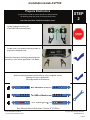
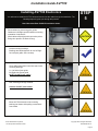
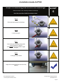
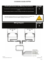
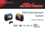
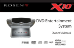
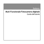
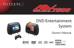
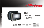
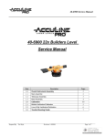
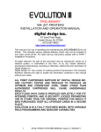
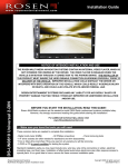
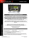
AV7700 Mercedes-Benz Seat Back Headrest Solution
AV7700 Installation Guide
Mercedes-Benz
NOTICE OF INTENDED INSTALLATION AND USE
ROSEN ENTERTAINMENT SYSTEMS VIDEO PRODUCTS ARE NOT INTENDED FOR VIEWING
BY THE DRIVER, AND ARE TO BE INSTALLED ONLY TO BE VIEWED BY REAR-SEAT
OCCUPANTS.
IMPROPER INSTALLATION COULD DISTRACT THE DRIVER OR INTERFERE WITH SAFE
OPERATION OF THE VEHICLE, WHICH COULD RESULT IN SERIOUS INJURY OR DEATH,
AND COULD ALSO VIOLATE STATE LAW.
ROSEN ENTERTAINMENT SYSTEMS DISCLAIMS ANY LIABILITY FOR ANY BODILY INJURY
OR PROPERTY DAMAGE THAT MAY RESULT FROM ANY IMPROPER OR UNINTENDED
INSTALLATION AND/OR USE.
Rosen Entertainment Systems
AV7700 System Installation Guide
STOP
Damage to the vehicle may occur
Do not proceed until process has been completed
CAUTION
CAUTION
Process must be carefully observed in order to reduce
the risk of damage to the accessory or vehicle
CRITICAL
Process must be carefully observed in order to ensure a
quality installation
TOOLS and EQUIPMENT
Specific tools and equipment recommended for this
process
SAFETY RISK
Observe safe practices, this process can be dangerous
and there is a risk of personal injury
TESTING and TROUBLESHOOTING
Content specific testing and troubleshooting points
Copyright 2010 All Rights Reserved
Installation Guide AV7700
PREPARING FOR THE INSTALLATION
Before you start, please read these critical steps below
STEP
1
BEFORE YOU START THE
INSTALLATION,
READ THIS GUIDE!
VISIT
Rosen Dealer Central
For the latest Updates, Corrections and Technical
Tips about this product and installation
www.RosenDealerCentral.com
CHECK THE BATTERY
Test the battery voltage to make sure it’s fully
charged to a minimum of 12.8 VDC
This only takes seconds and can save hours of
troubleshooting later.
TURN THE VEHICLE
OFF
Keep the Vehicle Off during the installation to
avoid setting various Vehicle Fault sensors
Keep the Vehicle OFF during the
installation
Failure to follow this may cause the AIRBAG
FAULT SENSOR to become enabled. Dealer
Service Departments charge a significant fee to
reset the Fault Sensor.
Rosen Entertainment Systems
AV7700 System Installation Guide
Copyright 2010 All Rights Reserved
AP2004-MB Rev A
Page 2
Installation Guide AV7700
Prepare Electronics
You will need to install the vehicle specific mounting brackets.
The following steps will guide you through this process
Note: Mercedes-Benz GL/ML/R installation shown
STEP
2
Locate hardware mounting kit.
(Part# MB100B contents shown)
Locate clean, non-abrasive working surface to
prepare the headrest units.
Determine the proper mounting bracket positions
according to your vehicle application. See Below
Attach mounting brackets to electronics by using 4 supplied screws
Spacing will vary by application.
Use image below as a reference.
Rosen Entertainment Systems
AV7700 System Installation Guide
Copyright 2010 All Rights Reserved
AP2004-MB Rev A
Page 3
Installation Guide AV7700
Routing Cable Through Headrest Bracket
You will need to route the cable through the headrest bracket. The following steps will guide you
through this process
Note: Mercedes-Benz GL/ML/R installation shown
STEP
3
Place the AV7700 electronics system on clean flat
surface.
Route cables through rectangular slots in
mounting brackets. (Shown Right)
Note: Critical process for proper cable routing
during installation
Attach Color-Matched Back Covers
Attach back covers to AV7700 electronics
STEP
4
Each AV7700 kit is supplied with color-matched
back covers
Align back cover with AV7700 mounting holes and snap into place
Rosen Entertainment Systems
AV7700 System Installation Guide
Copyright 2010 All Rights Reserved
AP2004-MB Rev A
Page 4
Installation Guide AV7700
Installing AV7700 Electronics
You will need to install the AV7700 electronics and route the cable through the seat backs. The
following steps will guide you through this process.
STEP
5
Note: Mercedes-Benz GL/ML/R installation shown
Route cables into seat along post guides.
Cables are Left/Right specific based on mounting
orientation of electronics
(Both cables will be black with connection points
being color specific. IE: Black & Grey)
Locate mounting bushings.
Bushings are labeled specific for Left or Right
for each post guide. See next step
CAUTION
Once cables have been routed into seat, insert
mounting bushings.
A = Left side of post guide
B= Right side of post guide
NOTE: Do NOT pinch cables
Both mounting bushings installed.
Caution: Do NOT pinch cables
Mount AV7700 electronics into mounting
bushings as shown while pulling excess slack
from cables
Rosen Entertainment Systems
AV7700 System Installation Guide
Copyright 2010 All Rights Reserved
AP2004-MB Rev A
Page 5
Installation Guide AV7700
Steps For Mounting Electronics Into Bushings
Below are steps to lock mounting brackets into bushings
Note: Mercedes-Benz GL/ML/R installation shown
STEP
6
Step A
Slide mounting brackets into bushings
Step B
Locate locking pin
Step C
Insert locking pin by sliding through both
locking positions on bracket
Note: Moderate force may be needed to engage
locking pin
Step D
Locking pin fully inserted
Image of both locking pins and electronics fully
installed
Rosen Entertainment Systems
AV7700 System Installation Guide
Copyright 2010 All Rights Reserved
AP2004-MB Rev A
Page 6
Installation Guide AV7700
Routing Harnesses and Making Connections
You will need to route the harnesses and make the power connections to the
vehicle.
Proper routing of cables is crucial to making sure cables do not get damaged
STEP
7
This system requires a minimum of 12V (+) ACC Switched and Ground (-) to operate. The
12V (+) ACC Switched source must be capable of supplying a minimum of 7A.
Wiring Diagram
Rosen Entertainment Systems
AV7700 System Installation Guide
STEP
8
Copyright 2010 All Rights Reserved
AP2004-MB Rev A
Page 7
Installation Guide AV7700
Initial Test, Reassembly, and Pre-delivery Re-test
You will need to fully test the system to ensure it is working and connected to the vehicle properly.
The following steps will guide you through this process
STEP
9
Step 1: INITIAL TEST (Do this BEFORE you reassemble any trim panels)
a. Reconnect the vehicle battery if needed
b. Install batteries into the remote control, headphones and game controllers
c. Start the vehicle (ensure that it is safe to do so, there are no tools or people under
the hood)
d. Perform the following steps on each headrest to ensure proper operation:
• Close and re-open the unit several times
• With the display open, insert a DVD (in good condition) and select play
• Check the audio on the IR headphones
• Press the Speaker button and adjust the vehicle radio frequency as needed
to check the audio
• Select and play the internal games
• Eject the disc
• Turn off the vehicle and wait for the unit to turn off
e. If the system does not function properly, reset the system by pressing and holding
the reset
button located near the eject button
Step 2: REINSTALL all trim panels removed during the installation using care not to damage
any harnesses
Step 3: PRE-DELIVERY AND RE-TEST
a. Start the vehicle (ensure that it is safe to do so, there are no tools or people under
the hood)
b. Perform the following steps
• Insert a DVD (in good condition) and select play
• Re-check IR headphones and FMT audio
• Eject the disc
• Remove the protective films and clean the unit as needed
c. Place the Owners Information package in the glove compartment
d. Place the IR headphones, remote control and game controller in a convenient location
Rosen Entertainment Systems
AV7700 System Installation Guide
Copyright 2010 All Rights Reserved
AP2004-MB Rev A
Page 8
Installation Guide AV7700
Installer Settings
The steps below will show you how to access the installer settings menu this process
STEP
10
To access install setup menu: use the remote control, press
“EJECT-ENTER-1-1-2-0”
•
•
•
•
To change AUX 2 input labeling, highlight AUX 2 label and
scroll left/right using arrows.
To select EXT FMM, highlight EXT FMM and select on.
POD ADDR is used to manually set pod address
AutoÆ address is based on which port the pod is plugged
into.
Selecting A or B allows you to manually set the pod’s
address
When manually selecting POD ADDR, an OSD will appear
on opposite pod displaying what pod it will be
Specifications
Supply Voltage
Current Consumption
Video Signal
Audio Signal
IR Audio Signal
Discs Played
:
:
:
:
:
:
12V (+) ACC negative ground system, 11-16VDC operating range
7A max operating
Composite video 1.0Vp-p 75 , NTSC/PAL
Audio Output : 2Vrms, line output
Channel A= 2.3 MHZ / 2.8 MHZ and Channel B= 3.2 MHZ / 3.8 MHZ
(1) 5” (12cm) DVD-VIDEO Disc
(2) Compact Disc (CD-DA/CD-R/CD-RW/MP3)
Operating Temperature : 0C to +60C
Note: Specifications and designs are subject to modification without notice.
Troubleshooting process
No headphone audio
The Headphone audio should be preset at all times, unless the MUTE is set to on
Solution: Press the MUTE Button to enable the audio and turn the MUTE OFF.
Solution: Confirm the headphones have fresh batteries and are turned on, and the ON LED
Indicator is Illuminated.
Missing Channel B Audio
System includes a monitor A and monitor B. Monitor A is channel “A” on headphones and monitor B
is channel “B” on headphones. If audio is not present, check the following.
Solution: Check A/B switch on headphones.
Solution: Reset the system
Solution: Check all cable connections
Rosen Entertainment Systems
AV7700 System Installation Guide
Copyright 2010 All Rights Reserved
AP2004-MB Rev A
Page 9
Installation Guide AV7700
Service and Optional Parts List
Part Number
AP1003
AP1008
AP1010
AP1007
AC3640
AP2003
AP1029
AP2020
AP1021
Description
Interface Module
Harness, Power
Harness, Interface
Control, Game System
Headphones, 2 CH. Fold Flat
Owner’s Manual
Warranty Card
Harness, Interface (Black w/ Gray)
Harness, Interface (Black w/ Black)
Part Number
AP1011
AP1043
AP1015
AP2001
AP2002
AP2004
AP1017
Description
Harness, AUX IN
Remote Control
Mounting Bracket
Monitor/Electronic w/ DVD
Quick Start Guide
Installation Guide
Cable Routing Tool
www.RosenEntertainment.com
Rosen Entertainment Systems
AV7700 System Installation Guide
Copyright 2010 All Rights Reserved
AP2004-MB Rev A
Page 10