1
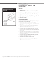
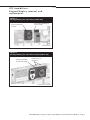
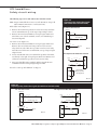
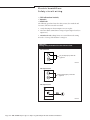
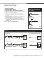
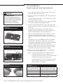
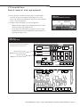
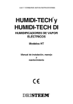
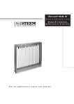
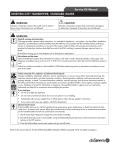
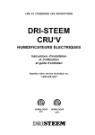
Vapor-logic® 3
to Vapor-logic4
A daptor Boa rd
Installation Manual
Wa r n i n g s a n d c a u t i o n s
Wa r n i n g s a n d c a u t i o n s
WA R N I N G
Indicates a hazardous situation that could result in death or serious
injury if instructions are not followed.
CAUTION
Indicates a hazardous situation that could result in damage to
or destruction of property if instructions are not followed.
mc_051508_1145
WA R N I N G
Read all warnings and instructions
This page provides important safety instructions; it is intended to supplement — not replace — the humidifier's Installation,
Operation, and Maintenance Manual (IOM). Read the IOM that was provided with the humidifier before performing service or
maintenance procedures on any part of the system. Failure to follow all warnings and instructions could produce the hazardous
situations described here and in the IOM, resulting in property damage, personal injury, or death.
If the IOM is missing, go to http://www.dristeem.com/ds_lit.jsp to download a replacement.
mc_071608_0910
Hot surfaces and hot water
Steam humidification systems have extremely hot surfaces, and water in tanks, electrode cylinders, steam pipes, and dispersion
assemblies can be as hot as 212 °F (100 °C). To avoid severe burns, allow the entire humidification system to cool.
Follow the cool-down procedure in the humidifier's IOM before performing service or maintenance procedures on any part of the
system.
mc_071608_0911
Shut down the energy source
Before performing service or maintenance procedures on any part of the humidification system, verify that all energy sources
are off. Energy sources can be electricity, gas, steam, or hot liquid. Failure to shut down the energy source could result in carbon
monoxide poisoning, fire, explosion, electrical shock, and other hazardous conditions. These hazardous conditions could cause
property damage, personal injury, or death.
Contact with energized circuits can cause property damage, severe personal injury or death as a result of electrical shock or fire.
Do not remove the shroud/cover, electrical panel cover/door, access panels, or heater terminal cover until electrical power is
disconnected.
Follow the shutdown procedure in the humidifier's IOM before performing service or maintenance procedures on any part of the
system.
mc_050808_1551
Page ii • DRI-STEEM Vapor-logic3 to Vapor-logic4 Adaptor Board Installation Manual
Ta b l e o f c o n t e n t s
Warnings and cautions . . . . . . . . . . . . . . . . . . . . . . . . . . . . . . . . . ii
Tools required:
Before beginning the upgrade . . . . . . . . . . . . . . . . . . . . . . . . . . . 2
• Needle nose pliers / wire cutter
Parts . . . . . . . . . . . . . . . . . . . . . . . . . . . . . . . . . . . . . . . . . . . . . . . . 2
GTS humidifiers:
Board removal and replacement
Removing Vapor-logic3, installing Vapor-logic4. . . . . . . . . . . . .
Transferring expansion board terminal blocks . . . . . . . . . . . . . . .
Keypad/display removal and replacement
Indoor GTS. . . . . . . . . . . . . . . . . . . . . . . . . . . . . . . . . . . . . . . . . . . . .
GTS with outdoor enclosure. . . . . . . . . . . . . . . . . . . . . . . . . . . . . . .
Safety circuit wiring
Leave safety circuit wired in series with one alarm. . . . . . . . . . . .
Separate safety circuit alarm signals into three alarms. . . . . . . . .
• Wire stripper
• #2 Phillips screwdriver
• 3/16" and 1/8" flat-tip screwdrivers
3
5
• 5/8" nut driver
6
6
8
8
Electric humidifiers:
Board removal and replacement
Removing Vapor-logic3, installing Vapor-logic4. . . . . . . . . . . . 10
Transferring expansion board terminal blocks . . . . . . . . . . . . . . 12
Keypad/display removal and replacement
Vaporstream and CRUV with mounted keypad/display . . . . . . 13
Vaporstream and CRUV with unmounted keypad/display. . . . 13
Vapormist and Humidi-tech. . . . . . . . . . . . . . . . . . . . . . . . . . . . . . 13
Safety circuit wiring. . . . . . . . . . . . . . . . . . . . . . . . . . . . . . . . . . . . . . . . 14
STS humidifiers:
Board removal and replacement. . . . . . . . . . . . . . . . . . . . . . . . . . . . . 16
Keypad/display removal and replacement
STS with mounted keypad/display. . . . . . . . . . . . . . . . . . . . . . . . . 18
STS with unmounted keypad/display . . . . . . . . . . . . . . . . . . . . . . 18
Safety circuit wiring. . . . . . . . . . . . . . . . . . . . . . . . . . . . . . . . . . . . . . . . 18
All Humidifiers:
Start-up and validation
Start-up. . . . . . . . . . . . . . . . . . . . . . . . . . . . . . . . . . . . . . . . . . . . . . . . 19
Test outputs. . . . . . . . . . . . . . . . . . . . . . . . . . . . . . . . . . . . . . . . . . . . 19
Test run. . . . . . . . . . . . . . . . . . . . . . . . . . . . . . . . . . . . . . . . . . . . . . . . 19
Vapor-logic4 adaptor board pin descriptions . . . . . . . . . Back cover
DRI-STEEM Vapor-logic3 to Vapor-logic4 Adaptor Board Installation Manual • Page 1
Before beginning the upgrade
Before beginning the upgrade
Before disconnecting power
• V
erify that the humidifier is operating
correctly; check the Vapor‑logic3 display
for alarms and messages.
• W
rite down the Vapor-logic3 configuration
string. This may help during start-up
and commissioning after upgrading
to Vapor‑logic4. See the Vapor-logic3
Installation and Operation manual for
details on how to obtain the configuration
string.
Pa r t s
Make sure all parts listed below are included in the Vapor-logic3 to
Vapor-logic4 upgrade kit you received.
Table 2-1:
Vapor-logic3 (VL3) to Vapor-logic4 (VL4) adaptor board kits
Part No. 183503-001
CRUV®, GTS®04 indoor, GTS99 indoor, GTS99 outdoor, Humidi-tech®, STS®,
Vapormist®, and Vaporstream®
No.
Description
Qty.
1
VL3 to VL4 adaptor board
1
2
Mounting stand-off* for adaptor board
6
3
VL4 keypad/display
1
4
Molex® plug (installed on adaptor board)
2
Do not disconnect wires
5
Jumper for configuring safety alarms
1
Do not disconnect wires from terminal blocks.
Terminal blocks connect to pin locations with
matching pin numbers (see Figure 2-1). Match
numbers to avoid reversing terminal blocks.
6
Field conversion label**
1
7
Ferrite core (required for Humidi-tech humidifier)
1
• If upgrading an outdoor GTS, verify that
the new enclosure door is the same height
as the old door.
Figure 2-1:
Matching pin numbers on board and
terminal block
Part No. 183503-002
GTS04 outdoor with 46.5" (1180 mm) enclosure door height
(before March 2007)
No.
Description
Qty.
1
VL3 to VL4 adaptor board
1
2
Mounting stand-off* for adaptor board
6
3
VL4 keypad/display, fan, and bracket
1
4
Molex plug (installed on adaptor board)
2
5
Jumper for configuring safety alarms
1
6
Outdoor enclosure replacement door
1
7
Field conversion label**
1
®
Part No. 183503-003
GTS04 outdoor with 51" (1295 mm) enclosure door height
(March 2007 and later)
No.
Description
Qty.
1
VL3 to VL4 adaptor board
1
2
Mounting stand-off* for adaptor board
6
3
VL4 keypad/display, fan, and bracket
1
4
Molex plug (installed on adaptor board)
2
5
Jumper for configuring safety alarms
1
6
Outdoor enclosure replacement door
1
7
Field conversion label**
1
®
* For extra stand-offs, order Part No. 409595.
** For extra labels, order Part No. 800076.
Page 2 • DRI-STEEM Vapor-logic3 to Vapor-logic4 Adaptor Board Installation Manual
GTS humidifiers:
Board removal and replacement
Removing Vapor-logic3, installing Vapor-logic4
1. If upgrading an outdoor GTS®, complete Steps 1 through 3 in “GTS
with outdoor enclosure” on Page 6 before proceeding.
2. Remove GTS control access panel to access the subpanel, shown in
Figure 3-1.
3. Disconnect Vapor-logic3 keypad/display cable and ribbon cables
from Vapor-logic3 main board and expansion board(s). Ribbon
cables will not be re-used.
4. Torque all terminal block screws to 2.5 in-lb (0.28 N·m) to prevent
wires from pulling loose in Step 5.
WARNING
Shut down humidifier
Before performing any maintenance or
service procedures, shut off all electrical
power to humidifier using field-installed
fused disconnect, lock all power
disconnect switches in OFF position, and
close the gas shut-off valve.
5. Mark location of Vapor-logic3 main board on subpanel by making
corner marks on subpanel with felt-tipped marker.
6. Use pliers to pull terminal blocks from Vapor-logic3 main board.
Unscrew stand-offs, and remove board and stand-offs (they will not
be re-used).
7. Leaving adhesive backing paper on the six nylon stand-offs
packaged with Vapor-logic4 adaptor board, push stand-offs into
adaptor board mounting holes, as shown in Figure 3-2.
Figure 3-1:
GTS subpanel
Figure 3-2:
VL4 adaptor board stand-offs
VL3 main board*
VL3 GTS expansion boards*
* Not re-used
Keypad/display
Ribbon cables*
Top wire channel
cable
Stand-off
Bottom of VL4 adaptor board shown
DRI-STEEM Vapor-logic3 to Vapor-logic4 Adaptor Board Installation Manual • Page 3
GTS humidifiers:
Board removal and replacement
8. Plug Vapor-logic4 keypad/display cable into Display connection on
Vapor-logic4 adaptor board (see Figure 4-1). If present, plug laptop
or network cable into Ethernet connection on adaptor board.
Figure 4-2:
Determining LonTalk interoperability
VL3 board LonTalk connections
(if no wires, then no LonTalk)
9. If upgrading to Vapor-logic4 without LonTalk® interoperability
(see Figure 4-2), skip this Step. If upgrading to Vapor-logic4 with
LonTalk interoperability, disconnect wires from Vapor‑logic3
LonTalk pins and land them as instructed in Table 4-1.
Table 4-1
Landing LonTalk wires
Disconnect wire from this
Connect it to this pin on Vapor-logic4
Vapor-logic3 board LonTalk pin adaptor board LON ProtoCessor Module
Corner of VL3 main board shown
Ground
Ground pin P1-2, P2-4, P4-3, P6-3, or P19-3
A
P21A
B
P21B
Figure 4-1:
Vapor-logic boards
VL4 adaptor board (two stacked boards; top board shown)
P8
The Vapor-logic4 adapter board pin descriptions
are listed in Table 20-1 on the back cover.
P7
P6
P5
P4
6 5
T1
T2 T2 T2 T1 T1
P3
4 3 2 1
4
3
P2
P1
33 32 31 30
35 34
1
2
3
4
9 10
8
7
3
2
1
14 15 16
21 22 23 24
17 18 19 20
11 12 13
7 8 9 10
2
3
GTS EXPANSION BOARD 1
GTS
5
P11
VLC
6
1
5
21 22 23 24
VL4 keypad connection
(Display connection on bottom board)
LON ProtoCessor Module
P21B
17 18 19 20
Laptop or network connection
(Ethernet connection on bottom board)
GTS EXPANSION BOARD 2
VLC EXPANSION
P21A
6
7
8
P12
9 10 11 12 13 14 15
P13
P14
18 19 20 21 22 23 24 25 26 27 28 29
P15
P16
P17
P18
P19
VL3 main board
B
VL3
keypad
LonTalk®
network
A
35 34
LonTalk®
33 32 31 30
EXPANSION
T2 T2 T2 T1 T1
1
2
3
4 5
6
7
8
9 10 11 12 13 14 15
16 17
Page 4 • DRI-STEEM Vapor-logic3 to Vapor-logic4 Adaptor Board Installation Manual
18 19 20 21 22 23 24 25 26 27 28 29
GTS humidifiers:
Board removal and replacement
10.Make sure subpanel surface is clean and dry. Remove adhesive
backing paper from new stand-offs, and press adaptor board into
exact location where Vapor-logic3 board was mounted.
Figure 5-1:
Splitting interlocked terminal blocks
11.Land loose Vapor-logic3 terminal blocks on corresponding pin
locations of Vapor-logic4 adaptor board.
Notes: Some 4-pin terminal blocks are two interlocked 2-pin
blocks that will need to be split. See Figure 5-1.
Scrape away any pin hole or screw corrosion before landing
terminal blocks on Vapor-logic4 adapter board.
Not all Vapor-logic3 wire connections will be used for this
upgrade. Cap bare ends of unused wires with wire nuts,
and tuck them into wire channel.
12.Cut an 18-gauge, stranded wire long enough to reach terminals T2
and 33 on Vapor-logic4 adaptor board (Figure 5-2). Strip ends of
wire, land ends at terminals T2 and 33, and torque terminal screws
to 2.5 in-lb (0.28 N·m).
13.Configure either modulating or on-off duct high limit:
Figure 5-2:
Jumpering terminals T2 and 33
T2
Jumper
Top edge of VL4
adaptor board
33
• Modulating: Move Vapor-logic3 terminal block 24/25/26 to Pins
24/25/26 on Vapor-logic4 adapter board.
• On-off: Move wire from Vapor-logic3 Pin 26 to Pin 24 of same
terminal block. Then move terminal block to Pins 24/25/26 on
Vapor-logic4 adapter board.
Transferring expansion board terminal blocks
Leave the wires in the terminals when transferring the terminal blocks
from the Vapor-logic3 expansion board(s) to the Vapor-logic4 adaptor
board.
Note: To facilitate wire re-routing and provide slack, remove top wire
channel cover. Unbundle wires as necessary in channel and in
wiring harness leading to burners.
GTS humidifiers have one or two Vapor-logic3 expansion boards.
If upgrading from Vapor-logic3 with two expansion boards, land
terminal blocks from one expansion board at a time.
Vapor-logic4 adaptor board pin locations for Vapor-logic3 expansion
board terminal blocks are labeled gts expansion board 1 and gts
expansion board 2, as shown in Figure 4-1.
DRI-STEEM Vapor-logic3 to Vapor-logic4 Adaptor Board Installation Manual • Page 5
GTS humidifiers:
Keypad/display removal and
replacement
Figure 6-1:
Keypad/display mounting screws
(indoor GTS)
Indoor GTS
1. Remove GTS end panel (Figure 6-1) to access keypad/display
mounting screws.
2. Remove the four keypad/display mounting screws, and disconnect
cable from Vapor-logic3 keypad/display. Vapor-logic3 keypad/
display will not be re-used.
3. Plug cable into Vapor-logic4 keypad/display, position Vapor-logic4
keypad/display over opening, and tighten mounting screws.
4. Replace GTS end panel.
GTS with outdoor enclosure
Remove end
panel for access
to keypad/
display mounting
screws inside
of side panel.
OM-1222X
Outdoor GTS humidifiers require the following hardware changes to
provide clearance for the ventilation fan:
1. Remove outdoor enclosure door that matches height of
replacement door shipped with upgrade kit. Screws will be re-used,
but not door.
2. Unplug power connection at fan, and remove fan and bracket
(Figure 7-1). Fan and bracket will not be re-used.
3. Unclip Vapor-logic3 keypad/display from bracket, unplug cable,
and remove bracket. Bracket and Vapor‑logic3 keypad/display will
not be re-used.
4. Mount Vapor-logic4 keypad/display, fan, and bracket assembly on
subpanel. Use mounting screws provided and existing mounting
screw holes (see Figure 7-2).
5. Unclip Vapor-logic4 keypad/display from bracket, plug in cable,
and replace keypad/display on bracket.
6. Connect fan power using plug from Step 2, above.
7. Replace outdoor enclosure door with new door shipped with
upgrade kit. Re-use screws from Step 1.
Page 6 • DRI-STEEM Vapor-logic3 to Vapor-logic4 Adaptor Board Installation Manual
GTS humidifiers:
Keypad/display removal and
replacement
Figure 7-1:
VL3 keypad/display, fan, and brackets (outdoor GTS)
Remove fan and bracket
assembly
Remove VL3 keypad/display and
bracket assembly
GTS04PNLASM-50view
Figure 7-2:
VL4 keypad/display, fan, and bracket assembly (outdoor GTS)
Install VL4 keypad/display,
fan, and bracket assembly
Mounting screws (use
existing holes)
GTS04PNLASM-50_testwVL4view
DRI-STEEM Vapor-logic3 to Vapor-logic4 Adaptor Board Installation Manual • Page 7
GTS humidifiers:
Safety circuit wiring
Leave safety circuit wired in series with
one alarm
1. Make sure gray-handled jumper supplied
with upgrade kit is inserted into terminals
P3-3 and P3-4 on Vapor-logic4 adaptor
board (Figure 8-1).
2. Locate wire 801 that runs to expansion
board terminal T1, and land it at terminal
P3-3 on Vapor-logic4 adaptor board. If
wire 801 does not reach P3-3, use a longer
18-gauge, stranded wire. Torque terminal
block screws to 2.5 in-lb (0.28 N·m).
Proceed to “Start-up and validation” on
Page 19.
Figure 8-1:
Leaving safety circuit wired in series
with one alarm
VL3 expansion board
801
T1
h
24 VAC
DM-10097
VL4 adaptor board
P3
LW
801
h 24 VAC
P3-3
FPsw
P3-4
Gray-handled
jumper provided
with upgrade kit
DM-10098
Certain Vapor-logic3 alarm points are wired in series and register as
“Interlock Disable” when any of the following alarms is tripped: door
interlock, blocked flue, or low water.
Whether leaving alarm signals in series or separating them, you must
perform either the procedure at left or the procedure below.
Note: If needed, refer to the Vapor-logic3 wiring diagram and the
Vapor-logic4 Installation and Operation Manual for more
wiring information.
Separate safety circuit alarm signals into three alarms
• If GTS does not have a door interlock switch, perform only Steps
1 through 5 on Page 9.
• If GTS has a door interlock switch, perform only Steps 1 through 8
below.
Note: Torque terminal block screws to 2.5 in-lb (0.28 N·m). Torque all
other terminal connections to 7 in-lb (0.79 N·m).
Door interlock switch (Figure 9-1)
1. Remove wire 414 from terminal 14 on Vapor-logic3 main board.
Remove other end of wire from position 11 on low water relay, and
keep for re-use in Step 8.
2. Remove wire 414A from position 14 on low water relay. Land this
wire at terminal 14 on Vapor-logic4 adaptor board.
3. Locate wire 415A running between door interlock switch and
blocked flue switch. Remove this wire from both termination
points, and keep for re-use in Step 5.
4. Locate wire 415 running between terminal 15 on Vapor-logic3
main board and blocked flue switch. Remove fork connector end
from blocked flue switch, and connect it to door interlock switch
where wire 415A was located.
Blocked flue switch (Figure 9-1)
5. Locate wire 415A that was removed in Step 3: Connect one fork
terminal to NC (normally closed) contact. Run wire to P3-4
connector at top of Vapor-logic4 adaptor board. Cut wire to length,
strip end, and land it at terminal P3-4.
6. Using other end of wire 415A that was removed in Step 3: Land
remaining fork terminal at the C (common) contact on blocked
flue switch. Strip other end, land it at one of the h terminals
(24 Vac) on terminal strip at bottom of subpanel.
Low water circuit (Figure 9-1)
7. Locate wire 801 that runs to T1 terminal on expansion board that
was directly to the right of Vapor-logic3 main board. Remove end
of this wire, land it at position 11 on low water relay.
8. Locate wire 414 that was removed in Step 1. Land one end of this
wire at position 14 on low water relay. Land other end at terminal
P3-3 on Vapor-logic4 adaptor board.
Page 8 • DRI-STEEM Vapor-logic3 to Vapor-logic4 Adaptor Board Installation Manual
GTS humidifiers:
Safety circuit wiring
The following steps are for GTS without door interlock switch:
Figure 9-2:
Separating safety circuit alarm signals
(GTS without door interlock switch)
Note: Torque terminal block screws to 2.5 in-lb (0.28 N·m). Torque all
other terminal connections to 7 in-lb (0.79 N·m).
Blocked flue switch (Figure 9-2)
VL3 without
interlock
VL3door
without
door interlock
1. Remove wire 414A from position 14 on low water relay. Land this
wire at terminal P3-4 at top of the Vapor-logic4 adaptor board.
Main board
2. Remove wire 415 from terminal 15 on Vapor-logic3 main board.
Land wire at one of the h terminals (24 Vac) on terminal strip at
bottom of subpanel.
11 14
414
14
Low water relay
414A
Blocked flue switch
415
15
C
Low water circuit (Figure 9-2)
3. Remove wire 414 from terminal 14 on Vapor-logic3 main board.
Remove other end of this wire from position 11 on low water
relay. Land one end of this wire at position 14 on low water relay.
Land other end of this wire at terminal P3-3 at top of Vapor-logic4
adaptor board.
NC
Expansion board
801
T1
h 24 VAC
DM-10100
VL4VL4
adaptor
board
without
adaptor
board
withoutdoor
doorinterlock
interlock
4. Locate wire 801 that runs to T1 terminal on expansion board that
was directly to the right of Vapor-logic3 main board. Remove end
of this wire, and land it at position 11 on low water relay.
P3
24 VAC
h
11
801
14
5. Insert gray-handled jumper supplied with this upgrade kit into
terminals 14 and 15 on Vapor-logic4 adaptor board.
h
C
415
Proceed to “Start-up and validation” on Page 19.
LW
414
Low water relay
NC
P3-3
414A
Blocked flue switch
FPsw
P3-4
Gray-handled
jumper provided
with upgrade kit
14
15
DM-10102
Figure 9-1:
Separating safety circuit alarm signals (GTS with door interlock switch)
VL3 with doorVL3
interlock
with door interlock
VL4 adaptor
board with
door
VL4 adaptor
board
withinterlock
door interlock
Main board
14
P3
414
11
14
24 VAC
414A
h
Low water relay
15
h
Expansion board
T1
801
11
14
414
Low water relay
Blocked flue switch 415A
NC
C
Door interlock
415
801
14
h 24 VAC
LW
P3-3
Blocked flue switch
415A
415A
NC
C
FPsw
P3-4
414A
Door interlock
DM-10099
15
415
DM-10101
DRI-STEEM Vapor-logic3 to Vapor-logic4 Adaptor Board Installation Manual • Page 9
Electric humidifiers:
Board removal and replacement
Removing Vapor-logic3, installing Vapor-logic4
WARNING
1. Access humidifier subpanel as follows:
Shut down humidifier
Before performing any maintenance or
service procedures, shut off all electrical
power to humidifier using field-installed
fused disconnect, and lock all power
disconnect switches in OFF position.
• Vaporstream and CRUV: Open control cabinet door by
loosening the screws on the two door latches.
• Vapormist and Humidi-tech: Remove plastic shroud by
unscrewing four Phillips screws (Figure 10-1) securing shroud
to frame (save and re-use screws). Remove galvanized subpanel
cover by unscrewing two Phillips screws securing cover to
subpanel (save and re-use screws).
2. Disconnect Vapor-logic3 keypad/display cable and ribbon cables
from Vapor-logic3 main board and expansion boards, if any.
Ribbon cables will not be re-used.
3. Torque all terminal block screws to 2.5 in-lb (0.28 N·m) to prevent
wires from pulling loose in Step 5.
Figure 10-1:
Vapormist / Humidi-tech cover
enclosure screw cap detail
4. Mark location of Vapor-logic3 main board on subpanel by making
corner marks on subpanel with felt-tipped marker.
5. Use pliers to pull terminal blocks from Vapor-logic3 main board.
Unscrew stand-offs, and remove board and stand-offs (they will not
be re-used).
6. Leaving adhesive backing paper on the six nylon stand-offs
packaged with Vapor-logic4 adaptor board, push stand-offs into
adaptor board mounting holes, as shown in Figure 10-2.
7. Plug Vapor-logic4 keypad/display cable into Display connection
on Vapor-logic4 adaptor board (see Figure 11-1). If present,
plug laptop or network cable into Ethernet connection on adaptor
board.
OM-778-3
Figure 10-2:
VL4 adaptor board stand-offs
Stand-off
8. If upgrading to Vapor-logic4 without LonTalk® interoperability
(see Figure 11-2), skip this Step. If upgrading to Vapor-logic4
with LonTalk interoperability, disconnect wires from Vapor‑logic3
LonTalk pins and land them as instructed in Table 10-1.
Table 10-1
Landing LonTalk wires
Disconnect wire from this
Connect it to this pin on Vapor-logic4
Vapor-logic3 board LonTalk pin adaptor board LON ProtoCessor Module
Ground
Ground pin P1-2, P2-4, P4-3, P6-3, or P19-3
A
P21A
B
P21B
Bottom of VL4 adaptor board shown
Page 10 • DRI-STEEM Vapor-logic3 to Vapor-logic4 Adaptor Board Installation Manual
Electric humidifiers:
Board removal and replacement
Figure 11-1:
Vapor-logic boards
VL4 adaptor board (two stacked boards; top board shown)
The Vapor-logic4 adapter board pin descriptions
are listed in Table 20-1 on the back cover.
P8
P7
P6
P5
P4
6 5
T1
T2 T2 T2 T1 T1
P3
4 3 2 1
4
3
P2
P1
33 32 31 30
35 34
1
2
3
4
9 10
8
7
3
2
1
14 15 16
11 12 13
21 22 23 24
17 18 19 20
2
7 8 9 10
GTS EXPANSION BOARD 1
GTS
5
P11
VLC
6
3
5
1
VL4 keypad connection
(Display connection on bottom board)
21 22 23 24
LON ProtoCessor Module
P21B
17 18 19 20
Laptop or network connection
(Ethernet connection on bottom board)
GTS EXPANSION BOARD 2
VLC EXPANSION
P21A
6
7
8
P12
9 10 11 12 13 14 15
P13
P14
18 19 20 21 22 23 24 25 26 27 28 29
P15
P16
P17
P18
P19
VL3 main board
B
VL3
keypad
LonTalk®
network
A
35 34
LonTalk®
33 32 31 30
EXPANSION
T2 T2 T2 T1 T1
1
2
3
4 5
6
7
8
9 10 11 12 13 14 15
16 17
18 19 20 21 22 23 24 25 26 27 28 29
Figure 11-2:
Determining LonTalk interoperability
VL3 board LonTalk connections (if no wires, then no LonTalk)
Corner of VL3 main board shown
DRI-STEEM Vapor-logic3 to Vapor-logic4 Adaptor Board Installation Manual • Page 11
Electric humidifiers:
Board removal and replacement
9. Make sure subpanel surface is clean and dry. Remove adhesive
backing paper from new stand-offs, and press adaptor board into
exact location where Vapor-logic3 board was mounted.
Figure 12-1:
Splitting interlocked terminal blocks
10.Land loose Vapor-logic3 terminal blocks on corresponding pin
locations of Vapor-logic4 adaptor board.
Notes: Some 4-pin terminal blocks are two interlocked 2-pin
blocks that will need to be split. See Figure 12-1.
Scrape away any pin hole or screw corrosion before landing
terminal blocks on Vapor-logic4 adapter board.
Not all Vapor-logic3 wire connections will be used for this
upgrade. Cap bare ends of unused wires with wire nuts,
and tuck them into wire channel.
Figure 12-2:
Jumpering terminals T2 and 33
T2
Jumper
Top edge of VL4
adaptor board
33
11.Cut an 18-gauge, stranded wire long enough to reach terminals T2
and 33 on Vapor-logic4 adaptor board (Figure 12-2). Strip ends of
wire, land ends at terminals T2 and 33, and torque terminal screws
to 2.5 in-lb (0.28 N·m).
12.Configure either modulating or on-off duct high limit:
• Modulating: Move Vapor-logic3 terminal block 24/25/26 to Pins
24/25/26 on Vapor-logic4 adapter board.
• On-off: Move wire from Vapor-logic3 Pin 26 to Pin 24 of same
terminal block. Then move terminal block to Pins 24/25/26 on
Vapor-logic4 adapter board.
Transferring expansion board terminal blocks
(Vaporstream only)
Some Vaporstream humidifiers have a Vapor-logic3 expansion board.
Vapor-logic4 adaptor board pin locations for Vapor-logic3 expansion
board terminal blocks are labeled vlc expansion, as shown in
Figure 11-1.
Leave the wires in the terminals when transferring the terminal blocks
from the Vapor-logic3 expansion board to the Vapor-logic4 adaptor
board.
Note: To facilitate wire re-routing and provide slack, unbundle wires
as necessary.
Page 12 • DRI-STEEM Vapor-logic3 to Vapor-logic4 Adaptor Board Installation Manual
Electric humidifiers:
Keypad/display removal and
replacement
The Vapor-logic3 keypad/display will not be re-used after this upgrade.
Vaporstream and CRUV with mounted keypad/display
1. Push keypad/display straight up to disengage its mounting keyhole
slots, and pull it off of mounting plate.
2. Disconnect cable from the Vapor-logic3 keypad/display.
3. Plug cable into new Vapor-logic4 keypad/display, and mount new
keypad/display.
4. Close and tightly secure control cabinet door.
Vaporstream and CRUV with unmounted keypad/display
1. Disconnect cable from Vapor-logic3 keypad/display.
2. Plug the cable into new Vapor-logic4 keypad/display.
Vapormist and Humidi-tech
1. On backside of subpanel keypad/display mounting location,
disconnect cable from Vapor-logic3 keypad/display.
2. Remove the four Phillips screws securing Vapor-logic3
keypad/display to sub-panel (save screws and re-use), and remove
keypad/display from subpanel.
3. Position new Vapor-logic4 keypad/display on subpanel, and plug
cable through subpanel and into back of keypad/display.
4. Secure keypad/display to subpanel using screws from Step 2.
DRI-STEEM Vapor-logic3 to Vapor-logic4 Adaptor Board Installation Manual • Page 13
Electric humidifiers:
Safety circuit wiring
• CRUV without door interlock,
• Vapormist
• Humidi-tech
The following procedure leaves the safety circuit (door interlock and
low water) wired in series with one alarm:
1. Verify that jumpers shown in Figure 14-1 are in place.
2. Land wire 802 at terminal P3-3 on Vapor-logic4 adaptor board (see
Figure 14-1).
3. Humidi-tech only: Clamp ferrite core around drain valve wiring.
Proceed to “Start-up and validation” on Page 19.
Figure 14-1:
Leaving safety circuit wired in series with one alarm
VL3 main board
Gray-handled jumper provided with
upgrade kit
DM-11260
VL4 adaptor board
Gray-handled jumper provided with
upgrade kit
VL4 adaptor board
DM-11261
Page 14 • DRI-STEEM Vapor-logic3 to Vapor-logic4 Adaptor Board Installation Manual
Electric humidifiers:
Safety circuit wiring
• CRUV with door interlock
• Vaporstream with door interlock
• Vaporstream with door interlock and/or cover interlock
Figure 15-1:
Leaving safety circuit wired in series
with one alarm
The following procedure leaves the safety circuit (door interlock and
low water) wired in series with one alarm:
VL3 expansion board (Vaporstream only)
1. Make sure gray-handled jumper supplied with upgrade kit is
inserted into terminals P3-3 and P3-4 on Vapor-logic4 adaptor
board (Figure 15-1).
2. Vaporstream only: Locate wire 801 that runs to expansion board
terminal T1 (Figure 15-2), and land it at terminal P3-3 on
Vapor-logic4 adaptor board. If wire 801 does not reach P3-3, use
a longer 18-gauge, stranded wire. Torque terminal block screws to
2.5 in-lb (0.28 N·m)
Proceed to “Start-up and validation” on Page 19.
801
T1
h
24 VAC
DM-10097
VL4 adaptor board
P3
LW
801
h 24 VAC
P3-3
FPsw
P3-4
Gray-handled
jumper provided
with upgrade kit
DM-10098
Figure 15-2:
Vaporstream or CRUV with door interlock; Vaporstream with door interlock and/or cover interlock
VL3 main board
VL3 expansion board (Vaporstream only)
DM-11262
VL4 adaptor board
VL4 adaptor board
DM-11259
DRI-STEEM Vapor-logic3 to Vapor-logic4 Adaptor Board Installation Manual • Page 15
STS humidifiers:
Board removal and replacement
1. Access Vapor-logic3 board by loosening screws on the two door
latches removing control cabinet door.
WARNING
Shut down humidifier
Before performing any maintenance or
service procedures, shut off all electrical
power to humidifier using field-installed
fused disconnect, lock all power
disconnect switches in OFF position.
Figure 16-1:
VL4 adaptor board stand-offs
Stand-off
2. Disconnect Vapor-logic3 keypad/display cable from Vapor-logic3
main board.
3. Torque all terminal block screws to 2.5 in-lb (0.28 N·m) to prevent
wires from pulling loose in Step 5.
4. Mark location of Vapor-logic3 main board on subpanel by making
corner marks on subpanel with felt-tipped marker.
5. Use pliers to pull terminal blocks from Vapor-logic3 main board.
Unscrew stand-offs, and remove board and stand-offs (they will not
be re-used).
6. Leaving adhesive backing paper on the six nylon stand-offs
packaged with Vapor-logic4 adaptor board, push stand-offs into
adaptor board mounting holes, as shown in Figure 16-1.
7. Plug Vapor-logic4 keypad/display cable into Display connection
on Vapor-logic4 adaptor board (see Figure 17-1). If present,
plug laptop or network cable into Ethernet connection on adaptor
board.
Bottom of VL4 adaptor board shown
Figure 16-2:
Determining LonTalk interoperability
VL3 board LonTalk connections
(if no wires, then no LonTalk)
8. If upgrading to Vapor-logic4 without LonTalk® interoperability
(see Figure 16-2), skip this Step. If upgrading to Vapor-logic4
with LonTalk interoperability, disconnect wires from Vapor‑logic3
LonTalk pins and land them as instructed in Table 16-1.
9. Make sure subpanel surface is clean and dry. Remove adhesive
backing paper from new stand-offs, and press adaptor board into
exact location where Vapor-logic3 board was mounted.
10.Land loose Vapor-logic3 terminal blocks on corresponding pin
locations of Vapor-logic4 adaptor board.
Notes: Some 4-pin terminal blocks are two interlocked 2-pin
blocks that will need to be split. See Figure 16-3.
Scrape away any pin hole or screw corrosion before landing
terminal blocks on Vapor-logic4 adapter board.
Corner of VL3 main board shown
Figure 16-3:
Splitting interlocked terminal blocks
Not all Vapor-logic3 wire connections will be used for this
upgrade. Cap bare ends of unused wires with wire nuts,
and tuck them into wire channel.
Table 16-1
Landing LonTalk wires
Disconnect wire from this
Connect it to this pin on Vapor-logic4
Vapor-logic3 board LonTalk pin adaptor board LON ProtoCessor Module
Ground
Ground pin P1-2, P2-4, P4-3, P6-3, or P19-3
A
P21A
B
P21B
Page 16 • DRI-STEEM Vapor-logic3 to Vapor-logic4 Adaptor Board Installation Manual
STS humidifiers:
Board removal and replacement
11.Cut an 18-gauge, stranded wire long enough to reach terminals
T2 and 33 on Vapor-logic4 adaptor board (Figure 17-2). Strip
ends of wire, land ends at terminals T2 and 33, and torque terminal
screws to 2.5 in-lb (0.28 N·m).
Figure 17-2:
Jumpering terminals T2 and 33
12.Configure either modulating or on-off duct high limit:
Top edge of VL4
adaptor board
Jumper
T2
33
• Modulating: Move Vapor-logic3 terminal block 24/25/26 to Pins
24/25/26 on Vapor-logic4 adapter board.
• On-off: Move wire from Vapor-logic3 Pin 26 to Pin 24 of same
terminal block. Then move terminal block to Pins 24/25/26 on
Vapor-logic4 adapter board.
Figure 17-1:
Vapor-logic boards
VL4 adaptor board (two stacked boards; top board shown)
The Vapor-logic4 adapter board pin descriptions
are listed in Table 20-1 on the back cover.
P8
P7
P6
P5
P4
6 5
T1
T2 T2 T2 T1 T1
P3
4 3 2 1
4
3
P2
P1
33 32 31 30
35 34
1
2
3
4
9 10
8
7
3
2
1
14 15 16
21 22 23 24
17 18 19 20
11 12 13
7 8 9 10
2
3
GTS EXPANSION BOARD 1
GTS
5
P11
VLC
6
1
5
21 22 23 24
6
7
8
P12
9 10 11 12 13 14 15
P13
P14
18 19 20 21 22 23 24 25 26 27 28 29
P15
P16
P17
P18
P19
VL3 main board
B
VL3
keypad
T2 T2 T2 T1 T1
LonTalk®
network
A
35 34
LonTalk®
33 32 31 30
EXPANSION
VL4 keypad connection
(Display connection on bottom board)
LON ProtoCessor Module
P21B
17 18 19 20
Laptop or network connection
(Ethernet connection on bottom board)
GTS EXPANSION BOARD 2
VLC EXPANSION
P21A
1
2
3
4 5
6
7
8
9 10 11 12 13 14 15
16 17
18 19 20 21 22 23 24 25 26 27 28 29
DRI-STEEM Vapor-logic3 to Vapor-logic4 Adaptor Board Installation Manual • Page 17
STS humidifiers
Keypad/display removal and replacement
The Vapor-logic3 keypad/display will not be re-used after this upgrade.
STS with mounted keypad/display
1. Push keypad/display straight up to disengage its mounting keyhole
slots, and pull it off of mounting plate.
2. Disconnect cable from the Vapor-logic3 keypad/display.
3. Plug cable into new Vapor-logic4 keypad/display, and mount new
keypad/display.
4. Close and tightly secure control cabinet door.
STS with unmounted keypad/display
1. Disconnect cable from Vapor-logic3 keypad/display.
2. Plug the cable into new Vapor-logic4 keypad/display.
Figure 18-1:
Leaving safety circuit wired in series
with one alarm
P4
TT
2. Torque terminal block screws to 2.5 in-lb (0.28 N·m).
lsw
801
4
3
2
The following procedure leaves the safety circuit (door interlock) wired
in series with one alarm See Figure 18-1.
1. Locate wire 801, and land it at terminal P4-1 on Vapor-logic4
adaptor board. If wire 801 does not reach P4-1, use a longer
18-gauge, stranded wire.
VL4 adaptor board
A12
Safety circuit wiring
h 24 VAC
Proceed to “Start-up and validation” on Page 19.
1
P4-1
Page 18 • DRI-STEEM Vapor-logic3 to Vapor-logic4 Adaptor Board Installation Manual
All Humidifiers:
Start-up and validation
Start-up
See the Start-up commissioning checklist in the humidifier’s
Installation, Operation, and Maintenance Manual. Before resuming
operation, verify that the current humidifier configuration matches
the Vapor-logic4 controller configuration. Refer to the Vapor-logic4
Installation and Operation Manual, and validate every parameter in the
Vapor-logic4 Setup menu.
Figure 19-1:
Field conversion label
When the upgrade is complete, fill out the Field
Conversion Label included with the upgrade kit, and
install it on the humidifier subpanel near the unit label.
When resuming operation, do not leave the humidifier unattended;
allow it to cycle through multiple fill cycles to verify that the
humidification system is functioning properly.
Test outputs
When completing an installation or repair, cycle all outputs, such as
fill valve, drain valve, etc., to verify operation. Go to the test outputs
section of the Diagnostics menu and scroll through each connected
output to verify operation. During testing, the humidifier mode
changes to Standby and the tank status changes to Test.
Test run
Vapor-logic4 has a test run capability to confirm system functionality.
This capability allows a technician to simulate a demand for steam
production when there isn’t one (such as when performing routine
maintenance). To confirm functionality, go to the test run section of
the Diagnostics menu. Set system demand percent and set test run time
duration. During testing, the humidifier mode changes to Standby and
the tank status changes to Test.
mc_102108_1350
Humidifier De-scaling Solution
Scale buildup on humidifier heaters and heat
exchangers acts as an insulator, reducing
humidifier performance while increasing
energy costs. To keep humidifiers operating
as efficiently as possible, remove scale with
DRI-STEEM's Humidifier De-scaling Solution,
available for purchase from your DRI-STEEM
representative or distributor.
The De-scaling Solution cleans without risk
of corroding humidifier tanks or welds. The
De-scaling Solution also cleans surfaces
unreachable by hand scraping.
DRI-STEEM's Humidifier De-scaling Solution
is the only approved cleaner/de-scaler for use
with DRI-STEEM humidifiers. Use of other
cleaners/de-scalers may void your DRI-STEEM
warranty.
mc_021908_1410-uni
DRI-STEEM Vapor-logic3 to Vapor-logic4 Adaptor Board Installation Manual • Page 19
Va p o r- l o g i c 4 a d a p t o r b o a r d
pin descriptions
For more information
www.dristeem.com
[email protected]
For the most recent production information
visit our Web site:
www.dristeem.com
Table 20-1
Vapor-logic4 adaptor board pin descriptions
Pin #
1, 2
Fill valve
3, 4
Drain valve
5, 6
Power vent (GTS), contactor (electrics)
7, 8
SDU / Area-type fan terminals
9
Fault Relay, N.C.
10
24 Vac, 1 amp max, COM
11
Connected by others, N.O.
12
Air flow switch input
13
Measure 24 Vac when opened
GTS: Pages 8 & 9
Electrics: Pages 14 & 15
STS: Page 18
16, 17
18
19, 20
DRI-STEEM Corporation
An ISO 9001:2000 certified company
U.S. Headquarters:
14949 Technology Drive
Eden Prairie, MN 55344
800-328-4447 or 952-949-2415
952-229-3200 (fax)
European office:
Marc Briers
Grote Hellekensstraat 54 b
B-3520 Zonhoven
Belgium
+3211823595 (voice)
+3211817948 (fax)
E-mail: [email protected]
Function
Safety circuit
24 Vac input, not used
+21V dc, supply
Tank temp sensor input
21
+21V dc, supply
22
RH / demand input
23
Common
24, 25, 26
On-off or modulating Duct High Limit
(see Step 13 on Page 5).
27
+21V dc, supply
28
Temp comp input
29
Common
30
Top probe
31
Center probe
Continuous product improvement is a policy of
DRI-STEEM Corporation; therefore, product features and
specifications are subject to change without notice.
32
Bottom probe
DRI-STEEM, GTS, Vapor-logic, Vapormist, and Vaporstream,
are registered trademarks of DRI-STEEM Corporation and
are filed for trademark registration in Canada and the
European community.
33
Ground
34
Pos analog output 0-15V dc, SSR, steam
valve
35
Common
Drane-kooler is a trademark of DRI-STEEM Corporation.
Product and corporate names used in this document may
be trademarks or registered trademarks. They are used for
explanation only without intent to infringe.
© 2011 DRI-STEEM Corporation
P21A, P21B
LonTalk (see Table 16-1)
DRI-STEEM products are warranted according to the terms and conditions of the standard
two-year Limited Warranty effective when the humidifier was purchased. See the literature
that was shipped with the humidifier for warranty information.
Form No. VL3-VL4-Convert-0511
mc_081308_1405
Page 20 • DRI-STEEM Vapor-logic3 to Vapor-logic4 Adaptor Board Installation Manual
Part
No. 890000-720 Rev D