1
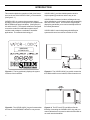
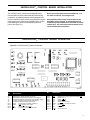
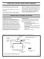
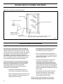
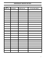
READ AND SAVE THESE INSTRUCTIONS
®
VAPOR-LOGIC2
MICROPROCESSOR HUMIDIFIER
CONTROL SYSTEM
INSTALLATION INSTRUCTIONS
and
OPERATIONS MANUAL
TABLE OF CONTENTS
TO THE PURCHASER AND THE INSTALLER:
Thank you for deciding to purchase the VAPOR-LOGIC®2 microprocessor-based humidifier control system. We have
designed and developed this microcontroller to give you total satisfaction and many years of trouble-free operation.
Observing the installation and operating practices described in this manual will assure you of achieving that objective.
We urge you to become familiar with the contents of this manual.
DRI-STEEM Humidifier Company
VAPOR-LOGIC2 Program Code Nomenclature .......................... 3
Introduction
VAPOR-LOGIC2 Microprocessor .............................................. 4
VAPOR-LOGIC2 Control Board
Installation ................................................................................ 5
Operation .................................................................................. 5
VAPOR-LOGIC2 Key Pad / Digital Display
Operation .................................................................................. 6
Sensing Device Placement and Wiring
Placement ................................................................................ 8
Control Precautions .................................................................. 8
Humidistats and Transmitters ................................................... 9
Proper Wiring Procedures ......................................................... 10
VAPOR-LOGIC2 Auto Scroll Information .................................... 11
VAPOR-LOGIC2 Main Menu Information .................................... 12
VAPOR-LOGIC2 System Status Information .............................. 13
System Fault & Disable Conditions ........................................... 14
Maintenance Service Record ..................................................... 15
Warranty ...................................................................................... 16
2
VAPOR-LOGIC®2 PROGRAM CODE NOMENCLATURE
A six digit VAPOR-LOGIC2 program code appears on the front of the control cabinet and on the wiring diagram inside
of the control cabinet. The program code specifies the parameters necessary for the VAPOR-LOGIC microprocessor
to control your system. An explanation of the program code is detailed below.
VAPOR-LOGIC2 PROGRAM CODE
A. Type of water level control:
VSDI with manual drain = D
Probe with manual drain = M
Probe with auto drain = A
EOS/DI drain = E
B. Operating mode:
Single staged
Externally staged
Zone valve
TP
SCR (DIGITAL)
=1
=2
=3
=4
=5
D. Temp. comp. options:
T = Option
O = Otherwise
E. Aquastat options:
A = Option
O = Otherwise
Steam valve
(ANALOG) = 6
F. Type of humidity sensing device:
N = None, for off-on
C = 0-135 ohms humidistat
D = 6-9 VDC humidistat
E = 4-20 MA humidistat
X = 4-20 MA transmitter
S = Special
C. VAV options:
V = Option
O = Otherwise
Example: Code number: VL2A4OOOX
V
L
2
A
4
O
O
O
X
A. Probe with auto drain
B. TP
C. Otherwise
D. Otherwise
E. Otherwise
F. 4-20 MA transmitter
3
INTRODUCTION
This manual explains the operation of and gives instructions for the use of the VAPOR-LOGIC®2 microcontroller.
(See figure 4-1.)
VAPOR-LOGIC2 is a custom microprocessor-based
humidifier control system developed to be compatible with
DRI-STEEM single stage humidifiers. (See figures 4-2,
4-3 and 4-4 below.) The versatile software is configured
to meet the needs of humidification system control
variations and to adapt to a multitude of humidifier
applications. The advanced technology of
VAPOR-LOGIC2 provides reliable operation while its
simple operating procedures make it easy to use.
VAPOR-LOGIC2 features include a self-diagnostic test
during initialization, end of season drain and compatibility
with most control inputs. A full-function integral digital
display/key pad allows you to monitor and adjust humidifier control parameters.
VAPOR-LOGIC2 controls single stage humidification
systems with control accuracies to within ±2% RH.
VAPOR-LOGIC
ACTUALRH: 35%
Figure 4-1: The key pad clearly displays the system
functions of the humidifier.
Figure 4-2: The VAPOR-LOGIC2 key pad is mounted on
the CRU humidifier control cabinet, located near the unit.
Figure 4-3: The VAPOR-LOGIC2 key pad is mounted on
the front of the VAPORMIST cabinet for easy access.
Figure 4-4: The STS and LTS humidifiers offer the
flexibility of mounting the VAPOR-LOGIC2 key pad on a
control cabinet that is mounted on either the humidifier or
on a wall near the humidifier.
4
VAPOR-LOGIC®2 CONTROL BOARD INSTALLATION
The VAPOR-LOGIC2 control board is shipped factory
mounted within a control cabinet with all internal wiring
completed. All software has been custom programmed
into your VAPOR-LOGIC2 system according to the original
order requirements. Refer to the VAPOR-LOGIC2 control
board drawing for detail of the board and connection
points. (See figure 5-1.)
Never run control system wires bundled with, or in
the same conduit as, line voltage wires.
All humidifier power wiring is represented on the
humidifier wiring diagram. A wiring diagram and
installation guide is attached to the inside of control
cabinet door. All instructions should remain in the
control cabinet after installation.
VAPOR-LOGIC2 CONTROL BOARD OPERATION
Figure 5-1: VAPOR-LOGIC2 printed circuit board
OM-613
No.
Description
No.
Description
J1
J2
J3
J4
J5
QC-1
QC-2
QC-3
QC-4
Alphanumeric Display Module Connector
Removable Terminal Strip to Reline Control Signals
Jumper PIN Selects Temperature Compensation Signal
Jumper PIN Selects High Limit Humidity Signal
Jumper PIN Selects Control Input Signal
Heat
24 Volt Output to Heater Contactor
Drain
Drain Value 24 Vac Output
Fill
Fill Valve 24 Vac Output
+21V
21 Volt DC Output to Freeze Stat
QC-5
QC-6
QC-7
QC-8
QC-9
QC-10
QC-11
QC-12
QC-13
FRZ
BR
OR
V10
YEL
+SSR
24H
24H
COM
Receives 2, 21 VDC Input From Freeze Stat
Water Level, A
Water Level, B
Water Level, C
Water Level Common
Modulating 1-9 VDC, DC Output
24 Vac Hot
24 Vac Hot
24 Vac Common
5
VAPOR-LOGIC®2 OPERATION
Figure 6-1 : Conductivity probe system
page 8.) Probe C provides low water protection for the
heating elements. If the water level falls below probe C,
the heat source is de-energized. (See figure 6-1.)
In addition to controlling the water level, VAPOR-LOGIC2
determines when the heat source is energized. If there is
a call for humidification, even during the fill cycle, the heat
source will stay on to provide continuous output.
Water level - A
Water level - B
Water level - C
OM-211
A conductivity probe system allows VAPOR-LOGIC2 to
control water levels for optimum operating efficiency. The
three-probe system is monitored by the VAPOR-LOGIC2
control, which performs all the necessary logic and timing
functions to provide total water level control and safety
shutdown.
VAPOR-LOGIC2 automatically maintains the water level
between the upper two probes A and B. When the water
level falls below probe B, the fill valve is opened until the
water level reaches the upper probe A. (A two second
minimum delay is incorporated in the skim time software
to ensure that turbulence does not cause an inaccurate
fill reading.) An adjustable skim time allows for an
extended skim period (2-60 seconds) to reduce mineral
concentration within the humidifier. This adjustment can
be accessed through the key pad main menu. (See
Auto Drain Sequence
VAPOR-LOGIC2 is pre-programmed to enter an automatic
drain, flush, and refill cycle based upon the actual time the
humidifier has produced steam. VAPOR-LOGIC2 is
factory-set for a 40 hour (accumulated “ON” time) drain
interval, with 8 minute drain and 8 minute flush durations.
When VAPOR-LOGIC2 initiates the auto drain sequence,
all demand for heat is turned off. The drain valve is then
opened to allow the tank to drain. At the end of the drain
cycle the fill valve is opened, initiating the flush cycle. The
drain valve remains open during the flush sequence for
drainage while the fill valve is open. At the completion of
the flush cycle, the drain valve closes, allowing the fill valve
to refill the evaporating chamber. The VAPOR-LOGIC2
timers are reset and the humidifier returns to normal
“AUTO” operation.
End of Season Drain
If there is no call for humidification for a 72 hour period,
VAPOR-LOGIC2 automatically drains the humidifier. The
drain valve is held open for one hour. The humidifier then
switches into “STDBY” mode until there is a call for
humidification, at which time VAPOR-LOGIC2 automatically refills the evaporating chamber and resumes normal
operation.
VAPOR-LOGIC2 KEY PAD / DIGITAL DISPLAY OPERATION
The system is provided with an LCD display that has two
lines with sixteen characters per line. This display
provides all of the control, monitoring, and setup information.
The key pad has four keys that are used to set and
control the system: MODE, SET, and the UP & DOWN
ARROW keys. (See figure 6-2.)
Figure 6-2:
VAPOR-LOGIC2 key
pad / digital display
6
VAPOR-LOGIC
ACTUAL RH: 35%
MODE
The MODE key is used to place the system into one of
four operating modes. Each time MODE is pressed, the
system will move to the next mode: AUTO, STANDBY,
DRAIN, and TEST.
The other three keys are multifunction keys whose
function depends upon the current system mode.
SET
The SET key, if pressed while the system is in either
AUTOMATIC or STANDBY mode, will place the system
into the Main Menu. (Note: if Access Code Protection
has been selected, an additional step is necessary. See
page 7 for further information.) Once in the Main Menu,
pressing SET will move the digital display through the
various Main Menu parameters.
VAPOR-LOGIC®2 KEY PAD / DIGITAL DISPLAY OPERATION
UP ARROW
The UP ARROW key is used, in the AUTOMATIC mode,
to transfer one of the automatic scrolling items on the
lower line to the upper line for constant monitoring. The
item selected will be updated every few seconds and will
remain isolated on the upper line while the other functions
will continue scrolling on the lower line. Items that can be
selected for constant monitoring are: Actual RH, Actual
High Limit RH, Glass Temperature, Time until Recommended Service, Time until Automatic Drain and Flush
Sequence, and Time until End of Season Drain.
If the system is in the DRAIN mode, pressing the UP
ARROW key will open the drain valve.
If the system is in the TEST mode, pressing the UP
ARROW key will start the test, or continue the test if it
was halted.
DOWN ARROW
The DOWN ARROW key is used, in the AUTOMATIC
mode, to sequence through the auto scrolling items of the
lower line. (To see the list of auto scrolling parameters,
turn to page 11.)
If the system is in the DRAIN mode, pressing the DOWN
ARROW key will close the drain valve.
If the system is in the TEST mode, pressing the DOWN
ARROW key will halt the test, or if already halted, will
cancel the test.
OPERATING MODES
There are four operating modes: AUTO, STANDBY,
DRAIN, and TEST. These different modes allow you to
monitor and control the various operations of
VAPOR-LOGIC2. The digital displays vary considerably
from mode to mode. The tables on pages 10-13 will give
you all of the possible displays, as well as their descriptions, so you are able to understand what
VAPOR-LOGIC2 communicates through the digital
display.
AUTO MODE
The AUTO mode allows for the normal operation of
the humidifier. AUTO mode is the default mode of
VAPOR-LOGIC2 if power is interrupted.
In AUTO mode the upper line contains the review parameter you have selected and the lower line contains the
auto scrolling parameters. (Remember: the UP ARROW
key can be used to move through the possible review
parameters on the upper line, while the DOWN ARROW
key can be used to scroll through the parameters listed
on the lower line.)
STANDBY MODE
When in STANDBY mode, the control outputs are turned
off. Inputs continue to be monitored, and all programming
functions are available. However, no outputs are affected,
and the water level in the evaporating chamber is not
maintained. The drain timers and service timers do not
accumulate time.
DRAIN MODE
Similar to the STANDBY mode, the inputs are monitored
but no outputs are affected while the system is in DRAIN
mode. Programming functions are not accessible while in
the DRAIN mode. The DRAIN mode de-energizes the
heat source. While in the DRAIN mode, the drain valve
can be opened or closed with the UP and DOWN keys.
In DRAIN mode, the upper display will read “DRAIN
MODE” while the lower display reads either “DRAIN OFF”
or “DRAIN ON.”
TEST MODE
The TEST mode can turn on the control outputs one at a
time to verify that each is performing correctly. All other
functions are blocked. The TEST mode begins with a
flashing “TEST MODE” message for five seconds. After
this delay, the outputs are cycled individually. The heat
demand, the drain valve, and the fill valve are tested.
In TEST mode, the upper display will read “TEST MODE”
while the lower display indicates the status of the test, or
the output function being tested. For example, the lower
line display could read: “FILL ON.”
INITIALIZATION
When power is first applied to VAPOR-LOGIC2, a short
self-diagnostic test sequence is performed. During this
test, the microprocessor and the non-volatile EEPROM
memory are verified to be functioning properly. If a
fault is detected, the fault message is displayed and
humidifier operation stops. If no fault is detected,
VAPOR-LOGIC2 begins normal operation in the AUTO
mode.
Accessing and Setting Main Menu Parameters
In either AUTO or STANDBY Mode, press the “SET” key
to enter the Main Menu. (Note: The Access Code has
been factory set to “00,” and will not appear unless you
have reset the Access Code. You may set the Access
Code as you would any other parameter in the Main
Menu.)
7
VAPOR-LOGIC®2 KEY PAD / DIGITAL DISPLAY OPERATION
Once in the Main Menu, use the SET key to scroll
through the items until the item you want is shown.
Use the UP and DOWN ARROW keys to change or set
the parameter.
A service timer is included as a reminder to perform
periodic maintenance and service to the humidifier. The
SERVICE timer display is included in VIEW and SCAN
displays. The SERVICE timer advances when the control
is in the AUTO mode. When the timer reaches zero, the
message SERVICE is added to the SCAN display. Once
the service timer has reached zero, it will continue to
count, but in a negative fashion to indicate how many
operating hours have elapsed since time out.
SENSING DEVICE PLACEMENT AND WIRING
Sensing Device Placement
The location of the humidity sensing devices is very
important to achieve accurate humidity control. A
drawing of a typical small air handling system is shown
below (figure 8-1). For the best control, place the
humidity sensing device in the center of room, or just
inside of the return air duct (location “A”). This will
provide the least amount of variation caused by air flow
patterns and room temperature. Placement of the duct
high limit humidity sensing device (location “D”) must be
downstream from dispersion tubes a sufficient distance to
ensure steam absorption has taken place. Accurate
control of temperatures in rooms and ducts is also very
important to improve control of relative humidity.
Control Precautions
Unsatisfactory humidifier control accuracy may involve
more than just the controller’s capability to control the
system. Other factors that may play a role in overall
system control accuracy are:
•
Size of the humidification system.
•
Overall system dynamics associated with moisture migration time lags.
•
Accuracy of humidistats and humidity transmitters
and their location.
•
Dry bulb temperature accuracy in space or duct.
•
Velocities and air flow patterns in ducts and space
environments.
•
Electrical noise or interference.
Figure 8-1: Humidistat control or humidity and temperature transmitters recommended placement
Point of steam
absorption
High limit humidistat or high limit transmitter
placement for VAV applications
Outside Air
Air flow switch
Relief Air
Return Air
B
D
AHU
Air Handling Unit
Steam absorption
has taken place
B
C
B
A
A
B
North or NorthEast facing
window
LOCATION
A) Best
B) Fair
C) Poor
D) Best for duct high limit
humidistat
Temperature compensation transmitter located on lower
corner of the inside surface of double pane window glass
OM-360
8
SENSING DEVICE PLACEMENT AND WIRING
On/Off Humidistats*
DRI-STEEM may provide three types of on-off controls:
a wall or a return air, duct mounted humidistat, or a
pneumatic/electric relay.
Modulating Humidistats*
Humidistats can be supplied for either wall or duct
mounted applications. These humidistats are powered by
a 21 VDC supply provided by the VAPOR-LOGIC2 control
board. A 0-15 VDC modulated control signal is returned
to the VAPOR-LOGIC2 control board which modulates the
output of the humidifier.
To use a signal from a pneumatic humidistat,
DRI-STEEM can provide a transducer for a 3-20 psi
pneumatic input range. This pneumatic input is converted to a 0-135 ohm signal. This 0-135 ohm signal is
adaptable to the VAPOR-LOGIC2 control board.
*Humidity set-point is made at the humidistat.
Modulating Humidity Sensors with Transmitters
DRI-STEEM can supply sensors with transmitters for
either wall or duct mounted applications. They are
powered by VAPOR-LOGIC2 and have an output of 4-20
mA and a 0-100% RH range. (Humidity set-point is done
at the VAPOR-LOGIC2 keypad.)
OPTION: Variable Air Volume (VAV) Control Kit
When this system is ordered, a second modulating
humidity sensor with transmitter is supplied (for duct
mounting). This transmitter limits humidifier output during
periods of low air flow to prevent saturation of air being
humidified.
NOTE: The wiring diagram (found on the inside of
the humidifier control cabinet) will show proper
wiring for these controls.
Note: DRI-STEEM recommends using #18 gauge
plenum rated shielded cable for transmitter wiring
and grounding shield at a common point in control
cabinet. (See figure 9-1.)
OPTION: Aquastat
This option protects the humidifier from damage due to
freezing. Should the temperature of the water in the
humidifier drop to near freezing the aquastat will energize
the heat source as needed.
OPTION: High Limit Controller
This option is recommended for all duct humidifier
applications. It is usually set for 90 to 95% RH and
protects the duct system from condensation due to a rise
in duct RH or drops in air temperature or air volume.
OPTION: Cold Snap RH Offset
This option prevents condensation from forming on
windows during periods of frigid weather. It consists of a
temperature sensor with transmitter mounted on an
appropriate window to sense glass temperature. When the
glass temperature falls below the dew point, the RH set
point is automatically lowered. When the cold snap ends
and the glass temperature rises, the normal RH setpoint is
automatically restored.
Cold Snap Transmitter Placement (See figure 10-1.)
1.
Position the cold snap transmitter control box
on a wall adjacent to lower window framing and
route the temperature sensor umbilical cord
behind the wall and out through window
framework.
2.
Place the flat surface of the temperature
sensor tip on the lower corner of the glass
surface.
3.
Temporarily hold the sensor tip in place with
strips of masking tape.
4.
Apply a small amount of clear RTV silicone
adhesive over and around the sensor tip
(making sure the sensor tip is in contact with
the window glass).
5.
After adhesive has cured, remove masking
tape.
Figure 9-1: Shielded cable
Temperature
Transmitter
Shielded Cable
VAPOR-LOGIC 2
T+
Sensor
Tip
T-
OM-311
9
SENSING DEVICE PLACEMENT AND WIRING
Figure 10-1: Cold snap transmitter placement
Window framing
Thermostat control wires
Double pane window glass
Surface mounting
thermostat temperature
control box to wall
Typical sensor
umbilical cord routing
Temperature sensor tip, secured to inside surface of window
glass using clear RTV silicone adhesive around tip
OM-337
PROPER WIRING PROCEDURES
Electrical "noise" is generated by electrical equipment,
such as switching loads, electric motors, solenoid coils,
welding machinery, fluorescent light circuits, etc. These
stray electrical currents can produce undesirable effects in
the electronic control circuits that eventually can affect
controllability. The electrical "noise" or interference
generated from these sources (and the effects on controllers) is very difficult to define, but most common symptoms are erratic operation or intermittent problems.
Most noise problems can be prevented by using wiring
practices and techniques which do not allow coupling or
inducing of electrical interference into control circuits.
These simple wiring practices associated with
DRI-STEEM humidifier equipment should minimize
interaction of noise and controls:
• Humidifier and control cabinets must be
connected to a code approved earth ground.
• When routing electrical wiring inside the control
cabinet, separate line voltage wiring from low
voltage control circuit wiring.
• Use separate electrical conduits for line and
low voltage wiring from the humidifier to
humidity sensors, airflow switches, etc.
• Do not mix chassis or safety grounds with
current carrying commons. No safety grounds
should ever be used as a conductor or neutral
to return circuit current.
• The preferred method of external electrical
connections to humidistats, room/duct
humidity and temperature transmitters, and
control signal input connections from building
control systems is minimum #18 gauge plenum
rated wire cable of twisted pair type, BELDEN
#88760, including cable shielding and drain wire
for grounding.
• All grounding of shielded cable connections
should be returned to the control cabinet
and tied to the earth ground point. Do not
ground shield at the device end.
NOTE: Do not use shielded cable for probe wiring.
Individual #18 gauge stranded is recommended.
10
VAPOR-LOGIC®2 AUTO SCROLL INFORMATION
The following pages contain information about the digital read-outs that VAPOR-LOGIC2 displays on the key pad. This
includes a wide variety of present system conditions, faults, and programmable parameters that ultimately control the
humidification system. The charts are organized based upon when or why the information is communicated.
Auto Scroll:
The items that will continuously scroll on the lower line during normal humidifier operation are listed below. The current
conditions are monitored and communicated through VAPOR-LOGIC2. The items available for individual review on the
upper line are noted.
$ 8 72 6 &5 2 / / ' ( 6 &5 ,3 7 ,2 1
$ 8 72 6 & 5 2 / / 5 ( $ ' 2 8 7
/ 2 : ( 5 / ,1 ( ' ,6 3 / $ <
$ 9 $ ,/ $ %/ ( ) 2 5
8 3 3 ( 5 / ,1 (
5 ( 9 ,( :
Relative Humidity Set Point
"DESIRED RH __%"
NO
Actual Relative Humidity
"ACTUAL RH __%"
YES
Maximum High Limit Humidity
"MAX HL RH __%"
NO
Actual High Limit Humidity
"ACT HL RH __%"
YES
Window Glass Temperature
"GLASS TEMP –__ F"
YES
Total Percentage System Output
"SYS DEMAND __%"
NO
Time until Service Message Display *
(in hours)
"SERVICE __H"
YES
Time until Automatic Drain and Flush
(in hours)
"AUTO DRAIN __H"
YES
Time until End of Season Drain
(in hours)
"EOS DRAIN __H"
YES
Setpoint Temperature
Compensation Reduction
"TEMP COMP __%"
NO
* Clearing the Service Timer
1. Energize unit.
2. Once the unit has finished initializing, push the MODE
key until the display says STANDBY MODE.
3. Once in STANDBY MODE, push the SET button. If
the display says ENTER CODE, skip to step 7 now.
4. The display should now say SCAN TIME. Push the
SET button until the display says ACC CODE.
5. Push the 'Up Arrow' once to enter an access code
of 01. Press the MODE key.
6. After the display says SAVE MODE and returns to
the STANDBY MODE, press SET button again. The
display should now say ENTER CODE.
7. To reset the SERVICE Timer to the SERVICE
interval parameter value, a special Access Code
must be entered. Press the SET key to display the
ENTER CODE message. Use the UP and DOWN
keys to set the Access Code to '2345'. Press the
SET key a second time to enter the code. The
display will return to the AUTO MODE, but the
SERVICE Timer will be reset. The Access Code
parameter ACC CODE may be set to any non-zero
value and does not need to be set to the special
Reset Code.
11
VAPOR-LOGIC®2 MAIN MENU INFORMATION
Main Menu Descriptions:
The Main Menu items are available by pressing the SET key while in either AUTO or STNDBY mode. The SET key
also allows you to scroll through the items in the Main Menu. While in the Main Menu, you may view or change the
system parameters by following the instructions on page 8.
Note: If any of the options were not selected by the original customer humidifier order, that specific parameter would
be removed from the Main Menu.
If parameter values are changed, they take effect immediately without waiting for the EEPROM SAVE to effect the
system operation. (EEPROM is short for Electronically Erasable Programmable Read Only Memory chip.)
The following is a list of the parameters, their setting ranges, and their default settings.
IMPORTANT: Do not set "Cycle Rate" less than 15 seconds when time proportioning contactors.
* These parameters, if set to zero, will eliminate the function from the humidification system. You may re-select the
function at any time by changing the parameter in the Main Menu to a value other than zero.
12
VAPOR-LOGIC®2 SYSTEM STATUS INFORMATION
' ,* ,7$ / ' ,6 3 / $ < 6 < 6 7 ( 0 6 7$ 7 8 6
5( $' 287
6 < 6 7 ( 0 6 7$ 7 8 6 ' ( 6 &5 ,3 7 ,2 1
"AUTO MODE"
The system is in AUTO MODE, which allows for the normal operation of the humidifier. (Default mode at star tup.)
"STANDBY MODE"
The system is in STANDBY MODE, which turns off all
control outputs during periods of servicing. Programming
functions are available. Electrical power must be shut off
at the disconnect before servicing electrically heated
humidifiers.
"DRAIN MODE"
The system is in DRAIN MODE, which turns off all
control outputs during periods of servicing. Programming
functions are not available.
"TEST MODE"
The system is in TEST MODE, which is used to verify
the performance of the individual control outputs.
"DRAIN ON"
The Automatic or Manual Drain has been activated,
during normal operating procedures.
"FLUSHING"
The system is in the Flush Interval of the Auto Drain
se q u e n ce .
"EOS DRAIN ACTIVE"
"FILL ON"
"AQUASTAT ENABLE"
"BEGINNING TEST"
The humidifier has not been active for 72 hours and has
activated the End of Season Drain.
The Fill Valve has been activated.
The heater has been enabled or activated by the
aquastat.
When the test cycle has been initially activated, this pretest message appears.
"HEAT OFF"
This designates par t of the Heater Output test: heater
contactor/valve has been turned off.
"HEAT ON"
This designates par t of the Heater Output test: heater
contactor/valve has been turned on.
"DRAIN OFF"
This designates par t of the Drain Output test: drain valve
h a s b e e n cl o se d .
"DRAIN ON"
This designates par t of the Drain Output test: drain valve
has been opened.
"FILL OFF"
This designates par t of the Fill Output test: fill valve has
b e e n cl o se d .
"FILL ON"
This desiginates par t of the Fill Output test: the fill valve
has been opened.
"SERVICE"
DRI-STEEM recommends inspecting and, if neccessary,
cleaning your humidifier system at this time.
13
SYSTEM FAULT & DISABLE CONDITIONS
Fault Conditions
The system continuously monitors for a wide variety of FAULT conditions. When a FAULT occurs, the status of the
system is changed to “FAULT” and the appropriate description appears in the lower line display. A FAULT condition
shuts off all of the humidifier outputs.
All faults deactivate the demand for heat. If the fault is a “FILL” fault, the line voltage must be interrupted to reset the
system. All other faults are AUTOMATIC RESET, and the fault will automatically clear once the condition no longer
exists and the system then proceeds as normal.
6 < 6 7( 0 ) $ 8 / 7
5( $' 287
6 < 6 7 ( 0 ) $ 8 / 7 ' ( 6 &5 ,3 7 ,2 1
A failure condition has been detected
"FAULT
during self-diagnostics test.
SYSTEM ERROR"
(Microprocessor or EEPROM fault.)
"FAULT
LIQUID LEVEL
SEN "
An error has been detected in the
sequencing of the probe.
5 ( &2 0 0 ( 1 ' ( ' $ &7 ,2 1
Consult DRI-STEEM.
Clean probe rod assembly.
The FILL has not been completed
"FAULT
during the set FILL time. (Tank is not
FILL TIMER OVER"
full.)
Check water supply shut off valve.
Check inline strainer.
Check for voltage present at the valve
(when filling).
The DRAIN has not been completed
"FAULT
during the set DRAIN time. (Tank is
DRAIN FAULT ACT"
not empty.)
Check for plugged tank drain outlet, clean.
Check for voltage present at the valve
(when in DRAIN mode).
"FAULT
SENSOR"
The RH Transmitters or Temperature
Transmitter have detected invalid
readings (too low).
Check for open, shor ted, or incorrect wiring.
Disable Conditions
The humidifier may be disabled by three conditions. These disabling conditions are not faults as they are expected to
occur in normal operation of the system. They are temporary interruptions to the normal operation of the humidifier.
They are indicated by a message on the second line of the display. Once the condition has been corrected the
humidifier will resume operation automatically.
6 < 6 7 ( 0 ' ,6 $ %/ (
5( $' 287
5 ( &2 0 0 ( 1 ' ( ' $ &7 ,2 1
"AFPS DISABLE"
The Air Flow Proving Switch has
detected too little air flow.
"HL RH DISABLE"
The actual duct relative humidity has
Check for low duct temperature and proper
exceeded the programmed upper
air flow.
limit.
"LO WATER
DISABLE"
14
6 < 6 7 ( 0 ' ,6 $ %/ ( ' ( 6 &5 ,3 7 ,2 1
Check for proper air flow: blowers, filters,
coils, etc.
A low water level has been detected
Check water supply.
in the tank.
MAINTENANCE SERVICE RECORD
DATE
INSPECTED
PERSONNEL
OBSERVATION
ACTION PERFORMED
15
TWO YEAR LIMITED WARRANTY
DRI-STEEM Humidifier Company (“DRI-STEEM”) warrants to the original user that its products will be free from
defects in materials and workmanship for a period of two (2) years after installation or twenty-seven (27) months
from the date DRI-STEEM ships such product, whichever date is the earlier.
If any DRI-STEEM product is found to be defective in material or workmanship during the applicable warranty
period, DRI-STEEM’s entire liability, and the purchaser’s sole and exclusive remedy, shall be the repair or
replacement of the defective product, or the refund of the purchase price, at DRI-STEEM’s election.
DRI-STEEM shall not be liable for any costs or expenses, whether direct or indirect, associated with the installation, removal or re-installation of any defective product.
DRI-STEEM’s limited warranty shall not be effective or actionable unless there is compliance with all installation
and operating instructions furnished by DRI-STEEM, or if the products have been modified or altered without the
written consent of DRI-STEEM, or if such products have been subject to accident, misuse, mishandling, tampering, negligence or improper maintenance. Any warranty claim must be submitted to DRI-STEEM in writing within
the stated warranty period.
DRI-STEEM’s limited warranty is made in lieu of, and DRI-STEEM disclaims all other warranties, whether
express or implied, including but not limited to any IMPLIED WARRANTY OF MERCHANTABILITY, ANY
IMPLIED WARRANTY OF FITNESS FOR A PARTICULAR PURPOSE, any implied warranty arising out of a
course of dealing or of performance, custom or usage of trade.
DRI-STEEM SHALL NOT, UNDER ANY CIRCUMSTANCES BE LIABLE FOR ANY DIRECT, INDIRECT, INCIDENTAL, SPECIAL OR CONSEQUENTIAL DAMAGES (INCLUDING, BUT NOT LIMITED TO, LOSS OF PROFITS, REVENUE OR BUSINESS) OR DAMAGE OR INJURY TO PERSONS OR PROPERTY IN ANY WAY
RELATED TO THE MANUFACTURE OR THE USE OF ITS PRODUCTS. The exclusion applies regardless of
whether such damages are sought based on breach of warranty, breach of contract, negligence, strict liability in
tort, or any other legal theory, even if DRI-STEEM has notice of the possibility of such damages.
By purchasing DRI-STEEM’s products, the purchaser agrees to the terms and conditions of this limited
warranty.
16
ribased inks
Ag
:
co rn,
soybe
an
a
etable oils.
veg
Form No. VL2OM-0297
%
00
nd
Printed on recycled paper with
Printed on recycled
with agribased
inks
agribased
inks. paper
Minimum
10% Post
Consumer Waste
1
14949 Technology Drive • Eden Prairie, MN 55344
Telephone: 1-800-328-4447• In MN: (612) 949-2415
Fax: (612) 949-2933 • E-Mail: [email protected]
Copyright © 1997 DRI-STEEM Humidifier Company, Inc.
Printed in U.S.A.