1
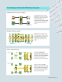
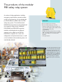
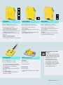
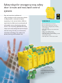
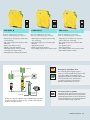
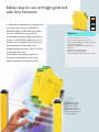
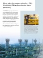
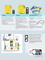
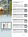
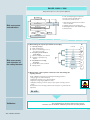
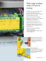
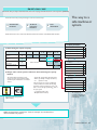
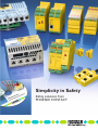
Simplicity in Safety
Safety solutions from
PHOENIX CONTACT
Definitely the right decision!
Progressive technical development leads to
ever faster and more complex production
systems. Often, conventional safety solutions
are no longer sufficient to protect the health
of the operating personnel and to prevent
damage to the production units. With this in
mind, Phoenix Contact has developed futureoriented safety components and systems for
various industrial functions and applications.
Our easy-to-use solutions that have been
developed in cooperation with numerous
users and certifying bodies such as TÜV
(German Technical Inspectorate) and BGIA
(Professional Institute for Safety at Work)
fulfill all relevant safety standards such as
EN 954-1, EN ISO 13849-1, IEC 61508 and
EN IEC 62061.
Effective cabling, safe installation
The PSR-SACB box conveniently
connects up to four safety switches to
one safety circuit and connects them to
the safety relay using a cable. In
addition, there are four alarm outputs
available that can be evaluated in the
controller.
2
PHOENIX CONTACT
Our safety technology is
characterized by the following
features:
• Easy planning, installation,
startup and maintenance
• High flexibility through
modularity
• Top quality and reliability
• Comprehensive service
Raiffeisen Fodder Plant, Kehl
The pet food manufacturer has expanded the existing
fieldbus solution in the grain mixing system with the
Interbus Safety system. The changeover from conventional
safety technology to Interbus Safety took just a weekend.
Additional systems are to be retooled in the light of the fast
conversion and lack of interruptions in the production
process.
Audi AG
Audi AG uses Interbus Safety in the A6 body shop. The
Interbus diagnostics with added safety functionalities
provides high system availability. In addition to the fact that
the response time has been reduced by half compared with
conventional safety technology, this was another reason for
opting for the safe bus system.
R
fe
I am
P
Safe system solution
with Interbus Safety
and Profisafe
OFIsa
The demand for cost-cutting applications and
more flexibility is growing fast and that
includes safety applications. With Interbus
Safety and Profisafe, machine and system
engineers have two systems dedicated
toward these and other requirements. The
main feature of the system is its simplicity:
Easy integration into existing networks, easy
to operate throughout the life cycle of the
system, and easy adaptation to suit your
changing application requirements. Further
features of the systems are short startup
times, high availability and maximum safety.
ThyssenKrupp Drauz Nothelfer GmbH
In a manufacturing cell in automobile
manufacturing, Interbus Safety ensures high
planning safety. A guaranteed switch-off time can
thus be parameterized for each safe output
channel.
Vocational school for metalworking and
electrical engineering in Hanover
As part of a final examination project, Interbus
Safety was added to a manufacturing system.
The students couldn't believe how easy startup
was: Read in the bus configuration – Link the
process data – Connect the input and output
variables with the safe modules – done!
4
PHOENIX CONTACT
Safe
Comprehensive
PLCopen module
libraries
As a manufacturer and product-independent
association, the PLCopen specifies function
modules for functional safety together with
its members and its external certification
centers. The PLCopen specification is an
international software standard that covers
the essential requirements of the user in the
field of functional safety for applications.
Phoenix Contact provides you with the
function modules in the form of various
libraries. Using them enables shorter startup
times as well as a higher availability of the
safety application.
The following basic applications are provided to the user as function
modules certified in accordance with PLCopen:
• Emergency stop
• Safety door monitoring
• Feedback monitoring
• Enable switch
• Reset block
• Electrosensitive protective
equipment
• Safety door extension
• Operating mode selector
switch
• Two-hand control
Program components already created can be combined and declared as a single
module to avoid repeated acceptance procedures for the same safety functions. It
is then merely necessary to check the module wiring again.
components and systems for e
Comprehensive
range of services
Specific know-how is required to implement
safe applications. In addition to adhering to
all the relevant standards, the mechanical and
plant engineer must also take into account
the future application of the machine as well
as the development of safety technology.
This is why we support you right from the
planning and programming stage, through
startup and after-sales service, and
throughout the entire life cycle of your safety
application. Speak to our specialists and
develop the technically and economically
best possible solution with the versatility to
adapt to new operating conditions and
technologies.
In addition to the
standard services in the
individual project
phases, we also provide
you with services in
safety technology over
the entire life cycle of
your machine or system.
Service
Engineering
Training &
professional
workshop
Project
Pla
nn
ing
n
ct g
tio
o je in
lla
a
Pr neer
t
gi
I ns
en
every application
p
rtu
Sta
O
i
rat
pe
on
fi t
tro
Re
The advantages of the modular PSR safety relay system
Multi-functional and easy to configure
The multi-functional master module
PSR-SDC4 is well-suited for emergency
stop functions, safety doors, light grids
and magnetic switches. The
corresponding safety equipment is simply
connected to the module. Programming
or additional switch settings are not
required.
Emergency stop
Light grid
Safety door
Magnetic switch
Modular extension possible
Additional extension modules can be
connected easily for modular expansion
to the PSR-SDC4 master module via the
PSR-TBUS. Cross-wiring for further
output contacts, for example, is not
required.
Master
Inputs
Outputs
Can be easily connected
Sensor box PSR-SACB4/4
Safety limit switches with N/O or N/C
contacts can be directly linked together in
the field by means of the PSR-SACB4/4
sensor box and connected to the
PSR-SDC4 master module for evaluation.
Safety door
PSR-SACB4/4
PSRSDC4
PSRURM4/B
PSRURD3
Safety door
Interface module PSR-SIM4
Safety limit switches can also be directly
linked to the PSR-SIM4 interface module
in the control cabinet. The PSR-SDC4
master module monitors the status of
each connected safety switch.
PSRSDC4
PSR-SIM4
PSRURM4/B
PSRURD3
PHOENIX CONTACT
9
The products of the modular
PSR safety relay system
A number of safety applications, including
emergency stop functions, protective doors
or light grid monitoring, can be realized with
just three different modules from the PSR
safety relay system. The multi-functional
PSR-SDC4 master takes over the evaluation of
the respective safety sensor. Additional
PSR-URM4/B and PSR-URD3 expansion
modules with delayed and non-delayed
contacts can be added via the DIN rail
PSR-TBUS as required. As a result, the
configuration and procurement costs, as well
as the installation and warehousing costs, are
considerably reduced.
PSR-SIM4
Order No. 2981936 (screw connection)
Order No. 2981949 (spring-cage connection)
• Interface module for the simple connection of
up to four safety switches with one N/O or N/C
contact each to a safety relay
(e.g., PSR-SDC4)
• Modular extension possible so that, for example,
eight or 12 safety switches can also be evaluated
• Max. safety category 3 in accordance with
EN 954-1
• Four signal outputs
In the body shop production lines of the
new Audi models A4 and A5, all safety
technology is realized based on the
modular PSR safety relay system. In the
individual applications here, only three
different modules are used: PSR-SDC4,
PSR-URM4/B and PSR-URD3. Due to
their compact design, the required
control cabinet space was reduced by
50%.
6
10 PHOENIX
PHOENIXCONTACT
CONTACT
PSR-SDC4
PSR-URM4/B
PSR-URD3/3
Order No. 2981486 (screw connection)
Order No. 2981677 (screw connection)
Order No. 2981732 (screw connection)
Order No. 2981499 (spring-cage connection)
Order No. 2981680 (spring-cage connection)
Order No. 2981745 (spring-cage connection)
• Safety relay master module for
monitoring light grids, emergency stop,
safety doors and magnetic switches
• Easy function selection without programming
or additional switch setting
• Max. safety category 4 in accordance with
EN 954-1
• Single or two-channel control
• Manual or automatic activation
• Two enabling contacts and one signal output
• Safety relay for contact extension
(slave module)
• Max. safety category 4 in accordance with
EN 954-1
• Four enabling contacts and one alarm and
signal feedback contact each
• Safety relay for contact extension
(slave module) with adjustable delay time of
0.3 - 3 seconds
• Max. safety category 3 in accordance with
EN 954-1
• Four delayed enabling contacts and one alarm
and signal feedback contact each
Magnetically coded safety
switches
PSR-SACB4/4
DIN rail connector
Order No. 2981871 (with 5 m cable)
PSR-TBUS
Order No. 2981884 (with 10 m cable)
Order No. 2890425
• Sensor box for the simple connection of
up to four safety switches with one N/O or
N/C contact each to a safety relay
(e.g., PSR-SDC4)
• Max. safety category 3 in accordance with
EN 954-1
• Four signal outputs
• Terminal plug available for unused slots
(Order No. 1539570)
• DIN rail connector
Magnetic safety switches with N/O
or N/C contacts are evaluated safely
using a special input logic. Use of the
PSR-SACB4/4 sensor box or
PSR-SIM4 interface module is
recommended if you are using
several switches of this type. The
safety switches can thus be easily
interconnected as well as connected
to the PSR-SDC4 safety relay
without additional wiring.
PSR-TBUS-TP
Order No. 2981716
• Terminal plug, incl. bridge for the feedback
circuit
PHOENIX
PHOENIXCONTACT
CONTACT 11
7
Safety relays for emergency stop, safety
door circuits and two-hand control
systems
Easy and error-free installation of
safety-related parts of the automation solution
is indispensable in mechanical and plant
engineering. In the control cabinet, different
signals from the field must be monitored and
evaluated for correct functioning and cross
circuits. Our universally applicable PSR safety
relays can be easily configured with the help of
external wiring and make use of innovative
connection technology. This reduces the
project planning and installation time.
PSR-ESM4_B
Order No. 2963776 (screw connection)
Order No. 2963925 (spring-cage connection)
• Safety relay for emergency stop and safety
door monitoring
• Max. safety category 4 in accordance with
EN 954-1
• Single or two-channel control
• Manual and monitored activation
• Optionally with two or three enabling contacts
and one alarm contact
• Optionally with or without safe isolation
In addition to the
additional labeling option,
the pluggable screw and spring-cage
terminal blocks of the PSR safety relays
are also coded in order to rule out the
possibility of a mix-up of the terminals on
a module.
8
12 PHOENIX
PHOENIXCONTACT
CONTACT
PSR-ESA4_B
PSR-ESA2_B
PSR-THC4
Order No. 2963763 (screw connection)
Order No. 2963802 (screw connection)
Order No. 2963721 (screw connection)
Order No. 2963941 (spring-cage connection)
Order No. 2963954 (spring-cage connection)
Order No. 2963983 (spring-cage connection)
• Safety relay for emergency stop and safety
door monitoring
• Max. safety category 4 in accordance with
EN 954-1
• Single or two-channel control
• Manual or automatic activation
• Optionally with two or three enabling
contacts and one alarm contact
• Optionally with or without safe isolation
• Safety relay for emergency stop and safety
door monitoring
• Max. safety category 2 in accordance with
EN 954-1
• Single-channel control
• Manual or automatic activation
• Four enabling contacts and one alarm contact
• Safety relay for two-hand control systems,
and for safety door monitoring
• Max. safety category 4 in accordance with
EN 954-1
• Two-channel control
• Automatic activation
• Two enabling contacts and one alarm contact
• Safe isolation between contacts
Safety door
PSR safety
relay
Emergency stop/safety door
For monitoring the emergency stop and
safety door circuits the PSR safety relays provide
up to eight enabling current paths and one
signaling current path. The modules with manual,
monitored activation also check that the
connected start button is functioning to
guarantee reliable detection of errors.
Reset button
Drive
Indicator light
Solid-state
contactor
3 ~V400
3 ~ 400
ACV AC
Example of a safety door application with a PSR-ESM4 safety relay that is
activated manually using a switch. The drive is reliably switched off via a
Contactron solid-state contactor.
Two-hand control systems
Two-hand control systems must be monitored for
simultaneity of less than 0.5 seconds in accordance
with the EN 574 standard. The time is checked and
evaluated reliably by the corresponding modules in
accordance with the category type III C.
PHOENIX
PHOENIXCONTACT
CONTACT 13
9
Safety relay for use with light grids and
safe time functions
In addition to monitoring the emergency stop
and safety door circuits, the PSR-ESL4,
PSR-ESAM4/8X1 and PSR-ESD-30 modules
are also suitable for the evaluation of
semiconductor outputs of light grids and laser
scanners. The PSR-ESD modules have time
functions with a dropout delay, and you can
choose between a safety relay with a
predefined delay time and a safety relay with
an adjustable delay time.
The modules are protected against any
subsequent manipulation of the setting
elements by means of an adhesive label.
PSR-ESL4
Order No. 2981059 (screw connection)
Order No. 2981062 (spring-cage connection)
• Safety relay for light grid, emergency stop and
safety door monitoring
• Max. safety category 4 in accordance with
EN 954-1
• Single or two-channel control
• Manual or automatic activation
• Three enabling contacts and one alarm contact
The ESL4 PSR safety relay
provides three enabling
contacts and one alarm
contact for the evaluation of
light grids up to cat. 4 in
accordance with EN 954-1
in a 22.5 mm design.
14
PHOENIX CONTACT
PSR-ESD-30
PSR-ESAM4/8X1
PSR-ESD-T
Order No. 2963912 (screw connection)
Order No. 2981800 (screw connection)
Order No. 2963996 (spring-cage connection)
Order No. 2981813 (spring-cage connection)
For order No., refer to the interface catalog 2007,
page 25
• Safety relay for light grids (types available on
request), emergency stop and safety door
monitoring
• Max. safety category 4 in accordance with
EN 954-1
• Single or two-channel control
• Manual or automatic activation
• Eight enabling contacts and one alarm contact
• Safe isolation between three contacts
• Safety relay for light grids, emergency stop
and safety door monitoring with adjustable
delay time of 0.1 - 30 seconds (0.2 - 300
seconds also available as an option)
• Max. safety category 3/4 in accordance with
EN 954-1
• Single or two-channel control
• Manual or automatic activation
• Two undelayed and two dropout delayed
enabling contacts
• Safety relay for emergency stop and safety
door monitoring; various module variants
available for predefined delay times of
0.5 - 30 seconds
• Max. safety category 3/4 in accordance with
EN 954-1
• Single or two-channel control
• Manual or automatic activation
• Three undelayed and two dropout delayed
enabling contacts and one alarm contact
Safe time function
Emergency
stop button
Drive
Applications such as locked protective covers or
dynamic processes that require delayed
contacts are connected accurately and reliably
with the corresponding PSR safety relays up to
cat. 3 in accordance with EN 954-1.
PSR safety relay
Frequency
converter
Locked safety
door
3 ~ 400 V AC
Example of a safety lock, in which the safety door can be opened only after
the time (for shutting down the drive) set on the PSR-ESD-3 module has
elapsed.
Light grids/laser scanners
OSSD (Output Signal Switching Device)
semiconductor outputs of light grids and laser
scanners ensure safe evaluation by the
corresponding PSR safety relays.
PHOENIX CONTACT
15
Safety relays for process technology (SIL),
shipbuilding (GL) and combustion plants
(EN 50156)
The PSR-ESP4 safety relays that have been
specially developed for safe semiconductor
outputs are characterized by high reliability,
low space requirement, simple wiring and
optimized switch-on behavior. Conventional
safety relays often have a very high inrush
current, which control systems interpret as a
short circuit. Thus, the PSR-ESP4, with its
improved current consumption when
switched on, is an ideal solution wherever
safe electrical isolation of the control system
from the application is required or the voltage
or power is to be adjusted.
16
PHOENIX CONTACT
Pillard Feuerungen GmbH
Pillard Feuerungen GmbH is involved exclusively
in furnaces for the cement, stone and earth
industry, power engineering and environmental
protection. Compact PSR safety relays that fulfill
the requirements of the EN 60204 and
EN 50156-1 standards ensure safe switching of
the check valves in fuel lines. The fuel supply is
thus reliably interrupted in the case of a fault.
Numerous approvals
PSR-ESAM4/3X1
PSR-ESP4
Order No. 2981020 (screw connection)
Order No. 2981114 (screw connection)
Order No. 2981017 (spring-cage connection)
Order No. 2981127 (spring-cage connection)
• Safety relay for emergency stop and safety
door monitoring and for safe electrical
isolation from the control system and the
peripherals
• Max. safety category 4 in accordance with
EN 954-1 and SIL 3 in accordance with
IEC 61508
• Single-channel control
• Manual or automatic activation
• Two enabling contacts and one alarm contact
• Safe isolation between contacts
• Safety relay for emergency stop and safety
door monitoring
• Max. safety category 4 in accordance with
EN 954-1 and SIL 3 in accordance with
IEC 61508
• Single or two-channel control
• Manual or automatic activation
• Three enabling contacts and one alarm
contact
• Safe isolation between contacts
• Wide-range input 24 V … 230 V AC/DC
Apart from the
certification in acc. with
IEC 61508 (SIL 3) that is
important for process
technology, the ESP4 PSR
safety relay has the
following additional
approvals:
• Approval as per the regulations of the
German Lloyd (GL), so that the relay
can also be used in shipbuilding and in
offshore systems
• Approval as per EN 50156-1 (safety
level 3) that allows its use in
combustion plants, steam generators,
waste heat boilers, rotary furnaces
and hot gas generators
IEC 61508 parts
Check valve
A1
Y1
Y2
A2
PSR safety
relay
PSR-ESP4
K1
K2
Failsafe PLC
31
13
14
32
23
24
As one of the first manufacturers, Phoenix Contact has
provided a comprehensive portfolio of safety relays certified in
accordance with IEC 61508 (SIL 3) which is being constantly
expanded. The IEC 61508 standard relevant for process
technology is based on four main pillars that help reduce the
residual risk:
• A complete documentation describing all product life cycle
phases
• The special requirements for the QM system to avoid errors
• Determining and calculating safety-related reliability
specifications, which are used to determine the time of a
functional test
• The requirements regarding diagnostic measures to be
implemented for detecting and rectifying the errors that
could possibly occur.
Example of electrical isolation of a safety PLC output from
the field using the ESP4 PSR safety relay.
PHOENIX CONTACT
17
Safety relays for contact extension
and universal use
The PSR-URM4 relays, which, like all PSR
safety relays, incorporate positively driven
contacts in accordance with EN 50205, are
suitable for the duplication of contacts. Up to
five N/O contacts and two N/C contacts have
been integrated into the housing with a width
of just 22.5 mm. These contacts are
mechanically interconnected and are
therefore always arranged in the same
position due to the fully positively-driven
operation. Welding of an N/O contact, for
instance, can thus be signaled in the case of an
error. The corresponding base module
evaluates the state and reliably prevents a
restart of the safety function when it is
demanded.
PSR-URM4_B
Order No. 2981033 (screw connection)
Order No. 2981046 (spring-cage connection)
• Safety relay for extending the number of
contacts
• Max. safety category 4 in accordance with
EN 954-1
• Single or two-channel control
• Five enabling contacts and one alarm and
readback contact each
• With or without safe isolation
Kirchenwald tunnel, Switzerland
Connecting gates between the two tubes of the Kirchenwald
tunnel serve as a way of escape from the other tube in the
case of an emergency. Special safety strips were used in
order to avoid the danger of being crushed when the gates
are activated. These safety strips comprise PSR safety relays
to extend the number of contacts of the evaluating devices
used.
18
PHOENIX CONTACT
PSR-URM/2X21
PSR-URM
Order No. 2981363 (screw connection)
Order No. 2963747 (screw connection)
Order No. 2963970 (spring-cage connection)
PSR-URM/4X1
Order No. 2981444 (screw connection)
Order No. 2981457 (spring-cage connection)
• Positively driven coupling relay
• Two PDT contacts
• Available for 24 V AC/DC and
120 V AC/DC
• Narrow housing width with only
17.5 mm width
• Permanently soldered-in relay
• Positively driven coupling relay
• With a choice of five N/O and two
N/C contacts, or with three N/O and
three N/C contacts
• Available for 24 V AC/DC and
120 V AC/DC
• Positively driven coupling relay
• Four N/O and two N/C contacts
• Available for 24 V AC/DC and
120 V AC/DC
• Permanently soldered-in relay
Extending the number of contacts
Emergency stop
button
Safety door
11
12
24
71
72
K1/K2
A1
A2
11
12
23
24
71
72
Indicator light
PSR-URM4/5X1_B
A2
23
PSR-URM4/5X1_B
PSR safety relay
A1
Often, more contacts are required than those
that are normally available. The positively driven
contact extension modules can be used in such
applications. Depending on the requirement,
they can be connected as modules.
K1/K2
33
34
43
44
33
34
43
44
53
54
63
64
53
54
63
64
Positively driven coupling relays
I
O
I
O
I
O
I
O
Contactor
Like all PSR switching devices, the coupling relays
for universal use also have positively driven
contacts in accordance with the EN 50205
standard. They can be used in all safety-related
applications due to the fully positively driven
N/C and N/O contacts.
Example of an emergency stop/safety door application with ESA4 PSR safety
relay that is supplemented with URM4_B contact extension modules.
PHOENIX CONTACT
19
Safety relays for downtime and speed
monitoring
If, for instance, the safety door is open when
setting up a machine or when working in
special operation mode, the drive speeds
must be monitored reliably. Unlike other,
often complex solutions, monitored speed
can be easily set in the PSR-RSM4 safety relay
using a software. The relay records the
speeds either using standard sensors or an
incremental encoder that has been
connected to the monitoring module with an
RJ45 cable adapter. If the set speed is
exceeded, the RSM4 module switches off the
machine safely using redundant N/O
contacts.
20
PHOENIX CONTACT
The speed monitoring module is configured via
the serial interface using a Windows-based,
easy-to-operate software.
PSR-SSM
PSR-RSM4
PSR-CONF-WIN1.0
Order No. 2981567 (screw connection)
Order No. 2981538 (screw connection)
Order No. 2981554
Order No. 2981570 (spring-cage connection)
Order No. 2981541 (spring-cage connection)
• Configuration software with connecting cable
for PSR-RSM4
• Safety relay for monitoring up to three
• Safety relay for downtime monitoring
different speeds during operation and
• Max. safety category 4 in accordance with
monitoring of downtime
EN 954-1 and SIL 3 in accordance with
• Max. safety category 4 in accordance with
IEC 61508
EN 954-1 and SIL 3 in accordance with
• Two-channel control
IEC 61508
• Automatic activation
• Two enabling contacts and two alarm contacts • Two-channel control
• Manual or automatic activation
• Two enabling contacts each for overspeed and
downtime and three signal outputs
• Easily configurable using the PSR-CONF-WIN
software
CABLE-:../8/250/RSM/…
For order no., refer to the
Interface catalog 2007,
page 28
• Cable adapter for PSR-RSM4
• Cable length 2.5 m
• For Siemens, Indramat, AMK, Heidenhain and
Aradex control systems (more types available
on request)
Downtime and speed monitoring
Safety door
switch
The PSR-SSM downtime monitor monitors the
downtime of a gearwheel or a gear rack. It is
controlled by two standard initiators and
additionally monitors cable or wire break.
The PSR-RSM4 speed monitor is used for
speed monitoring in automatic, special and setup modes and during downtime. The module is
controlled using two proximity switches or an
incremental encoder.
Operating mode
preselection
Drive
S35 S33 S34
PSR-RSM4
I1
I2
I3
A1
MI
A1
FO
A2
A2
MO1MO2
PSR safety
relay
Power
Output 1
Output 2
+S1 IN1 +S2 IN2
13
14
23
24
33
34
43
44
A1 S34 S33 S11
S12 S21 S22 A2
Emergency
stop button
Power
K1
PSR-ESM4
Frequency
converter
K2
31
13
14
32
23
24
PSR safety
relay
High
Example of speed monitoring of a drive using the engine-side
incremental encoder. An emergency stop is triggered if the speed is
exceeded when the safety door is open.
A
Low
High
B
Low
PHOENIX CONTACT
21
Interbus Safety – Maximum
safety based on a simple
functional principle
The safe control unit functions as an accept
unit in the Interbus Safety system, i.e. it
accepts the application output of the
standard control system. Thus, you can
create the standard application in the usual
manner, program the safety technology
separately and get it accepted. We provide
function modules that have been certified in
accordance with PLCopen for standard
applications such as emergency stop or safety
door monitoring. Not only do the modules
minimize programming, but they also
increase the clarity of the solution.
Safety protocol
Safety
data
The Interbus Safety
protocol
Safety
code
Data
Data
Communication between
the safe control system and
the safe devices takes place
via the Interbus Safety protocol.
The safe protocol data is integrated into the
data flow of the standard Interbus system just
like normal device data. The integrated safety
protocol can be evaluated only by the safe
components.
Industrial PC
Control system
Grille
Profinet
Profinet Proxy
and Interbus
Master with
integrated safe
control system
Safe I/O component
with IP20 protection
I/O
component
with IP20
protection
Emergency
stop button
Operator panel
Inline control system
Interbus Safety
Motor
Safe I/O component with
IP67 protection
Safe I/O component
with IP20 protection
Scanner
I/O component with
IP20 protection
Motor
ESPE
18
22
PHOENIX CONTACT
Enable
switch
Emergency stop
button
Data
Interbus Safety convinces with its
outstanding features:
Convenient integration
Interbus Safety can be retrofitted easily in existing automation
solutions. Here, the standard control system is replaced by a
Profinet Proxy and Interbus master with an integrated safe control
system. Depending on the requirement, the user can now operate
safe and standard devices on one bus line or separate them using a twocable solution.
Easy operation
Besides retaining the usual method of operation of the standard
Interbus system, the one-bit principle also contributes to easy
handling of Interbus Safety. The safe module electronics generate
a safe bit from the safe peripheral signals. The programmer
processes the safe bit in the safe programming software SafetyProg by
linking it to modules.
Precise diagnostics
The diagnostics functions of the standard Interbus system have
been transferred to Interbus Safety so that the user on site
knows which safety function has been triggered and why. While
the LEDs on the components display I/O or bus errors,
comprehensive diagnostics information is automatically shown in plain
text on the controller and via the diagnostics software Diag+.
Short response times
Since the Interbus system permits very short cycle times of 2 to
5 ms due to the transfer procedure, the process can be switched
off safely within a very short time. The response times can be
calculated in detail, since the Interbus protocol is deterministic in
structure. Usually, there are no fluctuations in the cycle time.
Emergency
stop
Standard
application
Safe
application
Actuator
If the emergency stop button is pressed, the safe control system
switches off the output using the safe output module. The safe
control system accepts the setting of the output through the
standard control system only when all input conditions have been
fulfilled again.
Guaranteed switch-off time
Interbus Safety is the only safe bus system that is currently able to
monitor the response time over the entire safety chain channel by
channel and to switch off the corresponding output in the case of
limit overshoot. The switch-off time to be monitored is simply
parameterized and guaranteed over the entire safety chain.
Maximum safety
Internal time switches, failsafe comparators, pulsed outputs, cyclesensitive inputs and the safety protocol ensure that the probability
of errors is minimal and lies within the limits defined for
SIL 3/IEC 61508 and cat. 4/EN 954-1. Current standards such as
EN ISO 13849-1 and EN IEC 62061 are also taken into account.
PHOENIX CONTACT
19
23
Interbus Safety – High-performance
control technology
Because it is integrated into the PC Worx
automation software, the Interbus Safety
system can be operated using the
corresponding control systems of our
comprehensive portfolio. The Profinet Proxy
and Interbus Master with an integrated safe
control system, for instance, acts as a link
between the safe and the standard
applications. The safe and the standard
components are integrated uniformly into the
turn-key solution by universal engineering.
Easy project planning of the system, uniform
diagnostics and intuitive programming using
PC Worx and SafetyProg simplify the handling
and the time required for setup.
Profinet
ETH
LNK
ACT
100
PLC
RUN
FAIL
MRESET
STP
13
15
14
19
16
17
18
Q1
I10
I11
I12
E
Q4
Profinet Proxy
and Interbus
Master with
integrated safe
control system
US
UM
Q2
Q3
UL
INLINE CONTROL
ILC 370 ETH
Ord.No.: 2737203
ACT
100
BA
RC
RD
TR
11
12
RUN/PROG
10/100 BASE-T
IB
REMOTE REMOTE
IN RES OUT
PRG
IL
RDY/RUN
BSA
FAIL
PF
Inline control system
Interbus Safety
Scanner
I/O component with
IP20 protection
Easy integration into Profinet networks
The Profinet proxy and Interbus master with an
integrated safe control system has an Interbus master
and a Profinet slave. The safe control system accesses
the Interbus Safety system via the module in order to
read in the safe inputs, to process the safe output
program and to control the safe outputs. The safe
application is programmed with the SafetyProg
software.
The SLC 400 PND-4TX-IB can be
integrated as a client into any Profinet
network as a control-systemindependent safety control system.
24
20
PHOENIX CONTACT
Integrated safety control system
Safety SLC 400 PND-4TX-IB
IBS S7 400 ETH SDSC
Order No. 2985563
Order No. 2819558
• Profinet Proxy and Interbus Master with
integrated safe control system
• Max. 126 safe input and output modules
• Pluggable CF-Flash parameterization
memory
• 10/100BASE-T Ethernet connection, RJ45,
4 port switch
• Max. safety category 4 in accordance with
EN 954-1, PL e in accordance with
EN ISO 13849-1 and SIL 3 in accordance
with IEC 61508 (EN IEC 62061)
• Interbus Safety controller board with
integrated safe control system
• Max. 126 safe input and output modules
• Pluggable CF-Flash parameterization
memory
• 10/100BASE-T Ethernet connection, RJ45,
single port
• Max. safety category 4 in accordance with
EN 954-1, PL e in accordance with
EN ISO 13849-1 and SIL 3 in accordance
with IEC 61508 (EN IEC 62061)
System packets
System packets
ILC 350 PN IB-SAFETY KIT
IBS S7 400 ETH SDSC SYSKIT
Order No. 2916451
Order No. 2737575 (German)
ILC 370 PN IB-SAFETY KIT
IBS S7 400 ETH SDSC SYSKIT E
Order No. 2916561
Order No. 2737407 (English)
ILC 390 PN IB SAFETY KIT
Consists of the IBS S7 400 ETH SDSC module,
the SAFETYPROG 2 PRO software packet, a
programming cable, a parameterization
memory and the safety system documentation
in German or English
Order No. 2916671
Consists of the Safety SLC 400 PND4TX-IB module, the ILC 350, 370 or
390 PN control system and an
Ethernet cable
The high performance of the safety
control system and its synchronization
with reference to Interbus cycles
contribute a great deal to the fast
response time of the entire system and
allow it to be monitored at all. The
following features affect the
performance positively:
• Runtime of the safe function modules
within milliseconds
• Clear separation of the safe control
system from the standard control
system to rule out mutual interference
• Two-channel parallel execution of the
safety program
• Synchronization with the Interbus
cycles in order to avoid loss of time
through scanning
• No additional load due to device or
channel drivers, since signal diagnostics
takes place on the components
PHOENIX CONTACT
21
25
Interbus Safety – Safe I/O
modules for the control cabinet
and the field
The inputs and the outputs of the safe I/O
modules with IP20 and IP67 protection,
which have been integrated in the application
are parameterized according to the
application. Here, you can opt for single or
two-channel signals, two test cycles,
diagnostics for short and cross circuit, an
equivalent or antivalent signal image and
currents up to 2 A for the outputs. In this
manner, all the single or two-channel
standard sensors and actuators can be
integrated into the safe fieldbus system. The
safe segment disabling is used to switch off
the following output components safely. In
combination with the safe Inline module
IB IL 400 SAFE 2, 400 V circuits can also be
switched off safely.
Our safe I/O modules can be used in all
standard safety applications such as the
emergency stop equipment, light curtains
and scanner applications as well as in
safety circuits for the safe switching of
contactors, motors, valves and ohmic and
inductive loads.
26
PHOENIX CONTACT
IBS RL 24 SDIO 4/4/8-LK
Order No. 2737520
• Rugged Line safety module with IP67
protection
• Four safety-oriented two-channel inputs and
outputs each or eight safety-oriented singlechannel inputs and outputs each
• Two pulsed outputs for supply to the UT1 and
UT2 inputs
• Max. 2 A per output (observe the derating)
• Max. safety category 4 in accordance with
EN 954-1, PL e in accordance with
EN ISO 13849-1 and SIL 3 in accordance with
IEC 61508 (EN IEC 62061)
IB IL 24 SDI 8-PAC
IB IL 24 SDO 8-PAC
IB IL 24 SDOR 4-PAC
Order No. 2985657
Order No. 2985754
Order No. 2985851
• Inline safety terminal with IP20 protection
• Four safety-oriented two-channel inputs each,
or eight safety-oriented single-channel inputs
each
• Two pulsed outputs for supply to the UT1 and
UT2 inputs
• Max. safety category 4 in accordance with
EN 954-1, PL e in accordance with
EN ISO 13849-1 and SIL 3 in accordance with
IEC 61508 (EN IEC 62061)
• Inline safety terminal with IP20 protection
• Four safety-oriented two-channel outputs
each or eight safety-oriented single-channel
outputs each
• Max. 2 A (observe the derating)
• Max. safety category 4 in accordance with
EN 954-1, PL e in accordance with
EN ISO 13849-1 and SIL 3 in accordance with
IEC 61508 (EN IEC 62061)
• Inline safety terminal with IP20 protection
• Two safety-oriented two-channel relays or
four safety-oriented single-channel relays (two
floating contacts each)
• Two readback inputs for recording external
circuit breakers and two pulsed outputs to the
readback inputs
• Max. safety category 4 in accordance with
EN 954-1, PL e in accordance with
EN ISO 13849-1 and SIL 3 in accordance with
IEC 61508 (EN IEC 62061)
IB IL 24 SDIO 4/4/1
IB IL 24 SAFE1-PAC
IB IL 400 SAFE 2
Order No. 2863740
Order No. 2861564
Order No. 2740795
• Inline safety terminal with IP20 protection
• Four safety-oriented two-channel inputs and
outputs each or eight safety-oriented singlechannel inputs and outputs each
• Two pulsed outputs for supply to the UT1 and
UT2 inputs
• Max. 2 A per output (observe the derating)
• One safety-oriented segment circuit output,
max. 6 A
• Max. safety category 4 in accordance with
EN 954-1, PL e in accordance with
EN ISO 13849-1 and SIL 3 in accordance with
IEC 61508 (EN IEC 62061)
• Inline safety terminal with IP20 protection
• Two safety-oriented inputs for direct
connection of emergency stop, safety door
and switching mat
• One safety-oriented segment circuit output,
max. 4 A
• Max. safety category 4 in accordance with
EN 954-1
• Inline safety terminal with IP20 protection
• Three N/O outputs,
max. 12 A/600 V AC, 5500 VA
• Three N/O relay outputs,
max. 12 A/600 V AC, max. 5500 VA
• Max. safety category 4 in accordance with
EN 954-1
PHOENIX CONTACT
27
Profisafe –
Safe I/O modules for the
control cabinet
• Up to category 4 according to EN 954-1
• Up to SIL 3 in accordance with EN 61508
and EN IEC 62061
fe
R
P
Depending on the bus coupler used, the
Profisafe modules of the Inline installation
system can be operated on Profibus-DP and
Profinet solutions so that these networks,
too, profit from the advantages of the safe
Inline modules. Within the Profisafe system,
safety functions with the following
requirements can be realized this way:
I am
OFIsa
Safety
application
Safety
application
Standard
application
Standard
application
PROFIsafe
layer
PROFIsafe
layer
Communication
protocol
Communication
protocol
PROFIsafe
layer with
V1 mode or
V2 mode
"Black
Channel"
1:1 communication relationship
PROFINET IO, PROFIBUS DP, backplane buses
• Up to PL e in accordance with
EN ISO 13849-1.
An Inline station can be made up of safe and
standard modules here, whereby a variety of
function terminals are available to the user.
The station is configured with fine granularity
with digital and analog inputs or outputs.
28
PHOENIX CONTACT
Black channel mechanism
In order to be able to transmit safe and standard data via a
bus cable, the Profisafe protocol is exchanged between the
safe control system and the safe I/O components via a "black
channel". Here, the safety telegrams with their independent
safety mechanisms are embedded in a standard telegram of
the Profinet system and are only unpacked in the respective
safety terminal.
IB IL 24 PSDI 8-PAC
IB IL 24 PSDO 8-PAC
IB IL PSDOR 4-PAC
Order No. 2985688
Order No. 2985631
Order No. 2985864
• Inline safety terminal with IP20 protection
• Four safety-oriented two-channel inputs
each, or eight safety-oriented single-channel
inputs each
• Two pulsed outputs for supply to the UT1
and UT2 inputs
• Max. safety category 4 in accordance with
EN 954-1, PL e in accordance with
EN ISO 13849-1 and SIL 3 in accordance
with IEC 61508 (EN IEC 62061)
• Inline safety terminal with IP20 protection
• Four safety-oriented two-channel outputs
each or eight safety-oriented single-channel
outputs each
• Max. 2 A per output (observe the derating)
• Max. safety category 4 in accordance with
EN 954-1, PL e in accordance with
EN ISO 13849-1 and SIL 3 in accordance
with IEC 61508 (EN IEC 62061)
• Inline safety terminal with IP20 protection
• Two safety-oriented two-channel relays or
four safety-oriented single-channel relays
(two floating contacts each)
• Two readback inputs for recording external
circuit breakers and two pulsed outputs to
the readback inputs
• Max. safety category 4 in accordance with
EN 954-1, PL e in accordance with
EN ISO 13849-1 and SIL 3 in accordance
with IEC 61508 (EN IEC 62061)
Inline bus coupler
Inline input/output terminals
or
or
IB IL 24 PS...
Easy integration
The safe Profisafe modules can be
integrated anywhere on the Inline
station, whereby mixed operation of
standard and safety terminals is possible.
The safe control system in the Profinet
or Profibus network is connected with
an appropriate bus coupler. In addition
to the Profisafe functions, the modules
can also be used in the Interbus safety
systems via the address switches.
Sensors and actuators are conveniently
integrated in the respective safe bus
system via the inputs and outputs of the
Profisafe modules. The settings can be
parameterized flexibly for single or twochannel I/O wiring as well as for
diagnostics.
PHOENIX CONTACT
29
Interbus Safety – Easy
programming of safety
networks
The faster the project planning, programming
and startup and the more detailed the display
of the diagnostics information, the higher the
machine or system availability. For this reason,
we have developed a software solution with
SafetyProg that will support you with a large
number of user-friendly functions, easy
handling and clear structuring when installing
your safe application. The safe interface is
supplemented with the software tools of
AUTOMATIONWORX Software Suite.
SAFETYPROG 2 PROG
Order No. 2985835
• Programming software for Interbus Safety systems
• Graphical interface in accordance with IEC 61131-3 in the
languages ladder diagram (LD) and function block
diagram(FBD)
• Including the configuration software Config+ and diagnostics
software Diag+
• Including the software libraries SafetyProg 2.x Basic (basic
functions of the Interbus Safety system) and SafetyProg2.x
system (diagnostics and handling of the Interbus Safety
system)
Easy handling of SafetyProg thanks to the fact that:
• The safe program is created independently of the external
wiring
• Certified modules are available for many safety functions
• Safety categories can be changed later by re-configuring
the peripheral components
• Complete processes can be pre-tested by means of
simulation of devices
• Programming errors are displayed in plain text
30
PHOENIX CONTACT
AUTOMATIONWORX Software Suite
CD AX SOFTWARE LIB
Order No. 2985660
(contains demo versions for registration)
Order No. 2819749
The Suite comprises the following software tools:
• PC Worx for project planning, programming and
diagnostics of Interbus, Ethernet, and Profinet-IO
networks
• Config+ for project planning and diagnostics of Interbus,
Ethernet, and Profinet-IO networks
• Diag+ for diagnostics of Interbus, Ethernet and ProfinetIO networks
• Diag+ NetScan for network diagnostics and monitoring of
several control systems
• Visu+ as a visualization system including OPC server
• WebVisit for visualization via the web server
• AX+ Basic for device parameterization through FDT
• Other tools and function block libraries
The CD-ROM comprises the following software products:
• Certified function modules (see below) to make
programming and the prevention of errors easier
• Example programs
• Driver
• Software tools
Clear structure
All necessary information is displayed structured and
separately using the multiple window principle. In
addition, the relevant documentation can be called
up for every peripheral component.
The function modules required for the basic operation of
AUTOMATIONWORX are available as freeware. Software
functions as universal part applications or the engineering
tools must be purchased. In order to preview their scope of
functionality, the functions can be loaded without a license
key. The appropriate key must be obtained for installation.
Easy device connection
The numerous parameterization settings make it
possible to connect all common sensors and
actuators to the Interbus Safety components.
The settings can also be imported if you want to
simplify the process. They are displayed in gray on
the interface and cannot be modified.
PHOENIX CONTACT
31
Interbus Safety –
Safe PLCopen function modules
for SafetyProg
Using the PLCopen function block
library facilitates the
implementation of your safety
functions in the Interbus Safety
system considerably. Safety functions can be
planned and programmed quickly and safely
with the help of the standardized and
certified modules. Validation of your
application becomes faster as separate
modules do not need to be created. The
Optimum support
for the user
All function modules implement the
required startup inhibits as an option. You
only need to parameterize and connect the
function modules in order to program the
startup inhibits required in your
application. It couldn't be simpler or faster!
function blocks provide diagnostics
information such as the condition of the
connected protective equipment, error
messages, acknowledgement signals or active
startup inhibits in plain text automatically via
the Diag+ diagnostic tool. The condition of
the safe application is thus presented clearly.
OSSD
Order No. 2916859
The library provides modules for safety
functions with electrosensitive safety
equipment right from the signal evaluation to
the test of the protective equipment including
all the required startup inhibits.
• SF_Espe (evaluation of electrosensitive safety
equipment)
• SF_TestableSafetySensor (test module for
electrosensitive safety equipment of type II)
32 PHOENIX CONTACT
I
O
Basic_SF
Order No. 2876067
The library supports you with basic safety functions including all the required startup inhibits.
Apart from the emergency stop button and the safety door monitoring with and without guard
locking, the control of safe actuators and their feedback circuit monitoring is also covered.
Furthermore, you can also carry out equivalence and antivalence evaluations of various signal
sources.
• SF_EmergencyStop (emergency stop
monitoring)
• SF_GuardMonitoring (protective door
monitoring without guard locking)
• SF_GuardLocking (protective door
monitoring with guard locking)
• SF_EDM (external device monitoring/
feedback monitoring)
TwoHand
• SF_OutControl (control of a safe output in
connection with an standard input including
all required startup inhibits)
• SF_Equivalent (checking the equivalence of
two signals)
• SF_Antivalent (checking the antivalence of
two signals)
Muting
Presentation of the Basic_SF library in
the safe programming software
SafetyProg
SafeMode
Order No. 2916846
Order No. 2916862
Order No. 2916875
The library contains safety functions for twohand circuits of type II and type III including all
necessary startup inhibits. The function
modules evaluate the signals of the connected
two-hand operating devices as per the
specified typification. The output signals are
formed on the basis of the signal evaluation.
• SF_TwoHandControlTypII (two-hand
circuit of type II)
• SF_TwoHandControlTypIII
(two-hand circuit of type III)
The library supports you in muting applications
with up to two to four muting sensors for
parallel and sequential muting including all
necessary startup inhibits. The function
modules evaluate the signals of the muting
sensors and the electrosensitive protective
equipment. The output signals are formed on
the basis of the defined muting sequences in
connection with the signal evaluation.
• SF_MutingPar_2Sensor (muting module for
parallel muting of two sensors)
• SF_MutingSeq (muting module for serial
muting of four sensors)
• SF_MutingPar (muting module for parallel
muting of four sensors)
The library supports you during the
implementation of safe functions such as the
selection of safe operating modes, the feedback
of the safe operating mode of safe drive
regulators by means of I/O coupling or the
enable switch monitoring for execution of the
selected safe operating mode (e.g. safe reduced
speed).
• SF_ModeSelector (execution of an operating
mode selection switch)
• SF-SafetyRequest (request for a safe operating
mode for a safe drive regulator)
• SF_EnableSwitch (evaluation of signals of an
enable switch)
PHOENIX CONTACT
33
Services in safety engineering
Following the motto "Simplicity in safety",
we have – in addition to our safety product
portfolio – developed a perfect service
concept that covers the entire life cycle of
your machine or system. We support you
right from the first consultancy appointment
on through concept planning, installation,
commissioning and operation, and system
modernization. You can decide whether you
want to make use of the know-how of a
In addition to the components used, safety also
depends on the employees involved. Our free safety
evening seminars are a good opportunity for you to
get acquainted with the subject. The standard
training program is structured such that it perfectly
qualifies everybody involved with the safety
engineering. Company-specific requirements are
covered through individual training programs and
workshops.
Phoenix Contact engineering or service
expert or whether you want to qualify your
employees accordingly.
Our safety expert team develops and supports
a concept individually adapted to your
requirements on the basis of the machinery
directive and other specifications. Benefit from
our comprehensive competence and years of
experience.
34
PHOENIX CONTACT
Safety Engineering
Safety Service
Order No. 2692089
Order No. 2851202
Statutory regulations must be adhered to even
before putting a machine on the market. Contact
us now for more information! Our engineering
experts are with you right from initial planning up
to startup and will support you during system
modernization. We work in close cooperation
with your employees to implement the safety
concept best suited to your application.
We are at your side with our extensive range of
services during the operation of your application.
We answer general questions about the
functionalities of individual components or assist
you during the operating process. Furthermore, you
can also consult our safety experts regarding
extending machines and systems.
•
•
•
•
In addition to the standard services in the
individual project phases, we also provide
you with services in safety engineering
over the entire life cycle of your machine
and system.
Development of the safety concept
Planning & project planning
Support for risk analysis
Support in the case of specific programming
requirements
• Generation of function modules
• Retrofit
•
•
•
•
•
Consultation
Startup support
Safety telephone support
Specialist hotline
Local servicing
24h-Safety-Hotline
+49/5281-946-2777
[email protected]
Service
Engineering
Training &
professional
workshop
Project
in
nn
Pla
g
n
ct g
tio
oje erin
a
l
r
l
P ne
ta
gi
Ins
en
rtu
S ta
p
o
ati
er
p
O
n
fi
tro
Re
t
PHOENIX CONTACT
35
Our training offer at a glance
Safety Technology Basics
New Safety Standards
Follow-up Safety Standards
Order No. 2850821
Order No. 2692335
Order No. 2792364
The training program informs you about the meaning
of safety engineering in mechanical and plant
engineering. The principles, components, and
solutions of safety-related control system technology
will be covered. Apart from the structure of
standards and the safety categories, the machinery
directive and other relevant concepts will be
explained.
The workshop explains the legal and normative
basics for the required machine safety. You are
provided with an overview of the standards, their
context as well as the differences in the
requirements regarding the functional safety of the
machine. The new standards EN ISO 13849-1 and
EN IEC 62061 are explained in detail using a
practical example.
You will apply the knowledge you have acquired about
the new standards in the New Safety Standards
workshop in practical applications. Using the example
of a production machine, you will be guided through
the process of designing safety-related parts of
machines and system controllers. This process
includes identifying and determining the protective
measures, determining the required capacity, as well
as the structure and the measures for validation and
verification.
Target group
Planners, project planners, service and maintenance
personnel, startup engineers, electricians, decisionmakers
Target group
Designers, system integrators and applications
engineers in mechanical engineering
Target group
Designers, system integrators and applications
engineers in mechanical engineering
Requirements
Basic knowledge of electrical and industrial
automation engineering
Requirements
Basic knowledge of electrical and industrial
automation engineering
Requirements
Basic knowledge of safety engineering and
participation in the New Safety Standards training
workshop
Program
• Examples of safety engineering in mechanical and
plant engineering
• Terms and definitions (cat., SIL, PL)
• Standard situation and guidelines
• Safety functions
• New machinery directive 2006/42/EU
• Basic requirements according to EN 60204-1,
IEC 61508, EN 954-1, EN ISO 13849-1 and
EN IEC 62061
• Responsibilities and law-abiding actions
Program
• Risk analysis for the safety on the machine
• Safety categories and deterministic error
determination as per EN 954-1 (ISO 13849-1:1999)
• Area of application, requirements and proof of
safety as per EN IEC 62061:2005
• Area of application, requirements and proof of
safety as per EN ISO 13849-1:2006
• Which standards must or can be used?
• What do the new standards mean for the
manufacturers of safety components as well the
user/mechanical engineer?
• Required specifications for safety-related reliability
Program
• Analysis of danger areas in a machine
• Definition of the requirements for safety functions
• Determining the required performance (PLr or SIL)
• Designing the control system architecture taking
into account the relevant parameters
(e.g. MTTFd, DC, PFHD, SFF)
• Determining the performance achieved (PL or SIL)
• Verification and validation
Duration: 1 day
Duration: 1 day
Duration: 1 day
36
PHOENIX CONTACT
Interbus Safety System Course
SafetyProg User Course
Training & Profi Workshop
Order No. 2884651
Order No. 2884680
Order No. 2710194
You will become familiar with the function and
structure of the Interbus Safety system and will get
to know the installation and connection
technologies of the safe signal generators. The
required safety category will be implemented during
the project planning of the system with one or two
channels accordingly. In addition, a startup will be
carried out using the Config+ and PC Worx
software tools.
The training program teaches you how to handle the
safe SafetyProg programming software. How to
adopt and configure safe modules is dealt with, as is
the communication between the safe and the
standard control system. You will parameterize the
safe bus devices in accordance with the safety
requirements. You will get acquainted with the
software programming options and the functioning of
the safe function modules.
Your employees will be qualified directly on the
application within the scope on the job training or a
professional workshop. Our service engineers will
explain the programming, bus and system diagnostics
functions, and the integration of bus and control
system technology.
Target group
Planners, project planners, startup engineers, service
and maintenance personnel
Target group
Planners, project planners, programmers
Target group
Programmers, startup engineers
Requirements
Basic PC knowledge as well as general knowledge of
electrical, automation and safety engineering
Requirements
Basic PC knowledge as well as general knowledge of
electrical, automation and safety engineering
Duration: 1 to 3 days
Program
• Interbus Safety basics
• Calculation of response and switch-off times
• Topologies, function, option for one or twocable solution
• Components, connection technology, basic
specifications, documentation
• SIL directive in accordance with EN IEC 62061
• Generation of an Interbus configuration
• Installation and connection technology
• Addressing options, data exchange between
standard and safe control systems
• Diagnostics using the Diag+ software
Program
• User management, rights, documentation, project
information
• Safety-relevant parameters
• Acceptance of bus configuration, addressing,
communication
• Parameterization of safe modules
• Integration of safe PLCopen function modules
• Program structure, programming guidelines, global
and local variables
• Generation of a safe program
• Diagnostics and history evaluation
Duration: 2 days
Duration: 2 days
The current prices and schedules of the
training programs can be found in our
Online catalog
www.eshop.phoenixcontact.com
under
AUTOMATION
AUTOMATIONWORX
Services
Safety engineering
PHOENIX CONTACT
37
Standards for functional
safety
The EU machinery directive 98/37/EU is
binding as a regulation for machine
manufacturers. In particular, the directive
specifies the prerequisites that must be met
before a new machine can be placed on the EU
market. The directive contains important
essential health and safety requirements for
the protection of the users. These must be
taken into account during the development
and design of a machine.
CE marking
Ready-to-use machines and systems must
have CE marking before they can be
placed on the market and operated. Based on
article 95 of the EU agreement, the manufacturer
uses the CE marking to declare that all the relevant
guidelines and specifications of the European Union
(EU) regarding free goods traffic have been adhered
to.
An excerpt from the 98/37/EU machinery directive
Type A standards
Basic safety
standards
Type B standards
Safety group
standards
EN 12100 – Safety of machines - Basic
concepts, general principles for design
EN 1050 – Safety of machines - Risk
assessment, part 1 Principles
EN ISO 13849-1 – Safety parts of control
systems, part 1 General principles for design
Harmonized since May 2007
EN IEC 62061 – Functional safety of safe
electrical, electronic and programmable
electronic control systems
Supplements EN 954-1: 1996 with quality
management and reliability aspects
Performance Level PL a to e
Harmonized since January 2006
Sector standard for the field of application of
mechanical engineering using the life cycle model
Safety integrity level SIL 1, 2 and 3
EN 60204-1 – Electrical equipment of machines
Type C standards
Product safety
standards
Machine safety standards giving detailed safety requirements on all significant dangers for a particular machine
or group of machines, e.g. injection molding machines.
The basic health and safety requirements specified in the machinery directive 98/37/EU and other internal market
guidelines are enforced using European standards, wherein a differentiation is made between basic standards (type A),
group standards (type B) and product standards (type C).
38
PHOENIX CONTACT
Area of application of the new safety standards
So far, the EN 954-1 had to be used as a proof for the
fulfillment of the essential health and safety requirements
specified in the machinery directive. Since today not only
electronics, but in particular programmable electronics have
established themselves in safety engineering, safety can no
longer be measured using the simple category system of
EN 954-1.
Due to the deterministic concept of the standard in which all
variables are clearly laid down, no more statements about the
probability of a failure can be made. As the successor
standards of EN 954-1, the new EN ISO 13849-1 and the
harmonized EN IEC 62061 standards provide a probalistic
approach that works with statistical probabilities.
Why does a supposedly identical field of application have two different standards?
EN ISO 13849-1
EN IEC 62061
Comes from EN 954-1:1996 and is supplemented
with quality management and reliability aspects
Sector standard for the field of machines that was
created on the basis of IEC 61508
Best suited for less complex systems
Can only be used for highly complex electronic
technology and here particularly for complex
programmable systems
Can also be used for other technologies apart from
electronics, e.g. pneumatic or hydraulic system
Procedure for proof of safety of electronic technology
based on IEC 61508
Suitable for proof of safety of devices as well as for
evaluation of risk reduction of the entire safety function
via tables
Suitable for proof of safety of devices as well as for
evaluation of risk reduction of the entire safety function
through calculation
From categories to probabilities
Performance Level
(PL)
EN ISO 13849-1
Mean probability of one
dangerous failure per hour
SIL as per
IEC 61508 and
EN IEC 62061
a
≥ 10 -5 to < 10 -4
–
b
≥ 3x10 -6 to < 10 -5
1
c
≥ 10 -6to < 3x10 -6
1
d
≥ 10 -7 to < 10 -6
2
e
≥ 10 -8 to < 10 -7
3
Max. acceptable safety
system failure
One risk failure every
10000 hours
One risk failure every
1250 days
One risk failure every
115.74 years
One risk failure every
115.74 years
One risk failure every
1,157.41 years
Unlike the deterministic concept of
EN 954-1, the EN ISO 13849-1 and
the EN IEC 62061 are based on a
probabilistic concept that takes into
account the probability of those
errors occurring that lead to a safety
function failure and categorizes them
as PL or SIL (high demand).
PHOENIX CONTACT
39
EN ISO 13849-1: 2006
Safety-related parts of control systems (SRP/CS)
In order to identify dangers and implement
preventive measures, EN ISO 12100-1
recommends an iterative process:
START
Determining limit values of the machine
Risk analysis
Risk identification
Risk assessment
and reduction
1. Determining the physical and time-related
limits of a machine
2. Identifying dangers and estimating risks
3. Estimating the risk for each identified danger
4. Risk assessment
Risk
assessment
Risk estimate
Risk assessment
Is the machine
safe?
No
Yes
END
Risk reduction
a) Determining the required performance level (PL)
F = Frequency and/or duration
of the danger
F1 = Seldom to frequent, short duration
F2 = Frequent to permanent, long
duration
Risk assessment
and structure of
the safety function
P = Possibilities for avoiding
the danger
P1 = Possible under certain conditions
P2 = Hardly possible
PL
Low risk
S = Severity of injury
S1 = Mild, reversible injury
S2 = Severe, irreversible injury to one or
more persons or death
a
P1
F1
P2
b
S1
P1
F2
P2
DC
P1
c
CCF
F1
P2
d
S2
P1
MTTFd
F2
P2
e
High risk
b) Design of the control system architecture and determining the
capacity attained
The PL of SRP/CS is determined by estimating the following parameters:
• Category (given as a defined structure)
• MTTFd (mean duration up to a dangerous failure)
• Diagnostic coverage degree (DC) from a table
• CCF (failure following a common cause) as a point system according to various
criteria
The attained PL is recorded using a table and must be equal to or greater than the
required PL.
PL ≤ PLr
Validation
40
PHOENIX CONTACT
The implementation of safety-related control system
functions must be checked. Validation proves that the safety function
Wide range of safety
relays in a narrow
housing
Our PSR safety relays have proven that
innovative safety solutions do not
necessarily need to be complex in order to
be able to fulfill the high safety
requirements of mechanical and plant
engineering. In addition to easy integration
and handling, our modules are
characterized in particular by their
compact, space-saving design as well as
their excellent quality and maximum safety
and reliability. Other advantages of the
safety relays are:
• Innovative connection technology
• Modular expandability
• Universal applicability on the basis of all
relevant approvals
Convenient connection technology
All PSR safety relays are available with
pluggable screw or spring-cage connection
technology. Here, the Twin spring-cage
connectors provide space for two lines per
connection point.
Quick expandability
The PSR TBUS DIN rail connector is used for
the modular expansion of the PSR safety
system with additional switching contacts.
Wiring costs are minimized due to the
"internal" pre-wiring.
PHOENIX CONTACT
7
}
PSR-TBUS
connector
PSR-TBUS
connector
PSR-TBUS-TP
+ UB 0 V
Enabling
feedback
circuit
INTERFACE PSR
use only
PSR-TBUS
Our PSR safety relay system reduces the space
requirement in the control cabinet, simplifies
wiring and minimizes storage costs. The
multifunctional PSR-SDC4 master relay is able
to monitor signals from different types of safety
sensors and switches. The PSR-SDC4, that can
also be used as a standalone safety relay, is
simple to setup and requires no programming
or setting of dip switches. Safety relays can be
easily connected to the PSR-SDC4 via
PSR-TBUS connectors for input or contact
extension. The PSR-TBUS forms an integral
backbone for the control and feedback signals
to and from the extension units and significantly
reduces the wiring typically associated with
safety relays.
INTERFACE PSR
use only
PSR-TBUS
The modular PSR safety relay system
with PSR-TBUS connection
PSR-TBUS
terminal plug
The safety-related wiring between the individual PSR modules is
enabled automatically via the PSR-TBUS DIN rail connector. Besides
the supply voltage, an enable signal and the feedback path of the
extension modules are led over the connector. The terminal plug closes
the feedback circuit in the system.
The contact extension
modules are automatically
connected to the master
safety relay via PSR-TBUS
DIN rail connectors. The modules
are quickly installed onto the
connectors via a simple swivel action.
8
PHOENIX CONTACT
EN IEC 62061: 2005
Functional safety of safety-related electrical, electronic and programmable electronic control systems (CE/E/PES)
The way to a
safe machine or
system
A reduction in the risk posed by the danger is carried out in three steps:
1
Constructive
measures
2
Technical
protective
measures
3
User
information
Detailed information can be found in the EN 1050 standard and in future, in the EN ISO 14121 standard
F Frequency and duration
a) Determining the required capacity
Effects
Death, loss of an eye
or arm
Permanent, loss of
fingers
Reversible, medical
treatment
Reversible, first aid
Severe S
4
Class 3 – 4 Class 5 – 7
SIL 2
SIL 2
3
2
Other measures
≤ 1 hour
5
> 1 hour to ≤ 1 day
> 1 day to ≤ 2 weeks
> 2 weeks to ≤ 1 year
> 1 year
5
Class
8 - 10
Class
11 - 13
Class
14 - 15
SIL 2
SIL 3
SIL 3
SIL 1
SIL 2
SIL 3
+
SIL 2
Probability of a dangerous
incident
SIL 1
1
SIL 1
Determination of the necessary SIL
W
4
3
2
Frequent
5
Probable
4
Possible
3
Seldom
2
b) Design of the control system architecture and determining the capacity
attained
Negligible
1
• SIL CL (SIL demand limit; SIL Claim Limit)
• PFHD (probability of dangerous failures)
• T1
(duration of use)
P Avoidance
The safety-related parameter for part
systems comes from the following values
specified by the manufacturer for certified
devices:
A1 S34 S33 S11
S12 S21 S22 A2
Power
PSR-ESM4
K1
K2
31
13
14
32
23
24
The part systems can consist of differently
connected devices for which the following
parameters must be specified, in order to be
able to record the appropriate PFHD value of
the part system:
• ∑ λ (Lambda, failure rate)
• SFF (Safe Failure Fraction)
Architecture of the safety function
(SRP/CS, SRECS)
+
Impossible
5
Possible
3
Probable
1
The standards are
presented in an extremely
simple manner for better
understanding.
fulfills the appropriate requirement. Tests, for example, are conducted and
documented for this purpose.
PHOENIX CONTACT
41
Safety-related parameters
EN ISO 13849-1
The following safety-related parameters must be recorded in accordance with EN ISO 13849-1 within the
scope of proof of safety:
Abbreviation
Explanation
PL
Performance Level
Discrete level that specifies the capacity of the safety-related parts of a control
system to execute a safety function under foreseeable conditions;
Classification from PL a (maximum probability of failure) to PL e
(minimum probability of failure)
MTTFd
Mean Time to Failure
dangerous
Mean duration till a dangerous failure takes place, which can be recorded with the
help of an analysis of the field data or by means of a prediction
B10d
Number of switching cycles during which 10% failed during a random test of the
observed worn components (e.g. electromechanical components)
TM
Mission Time
Planned duration of use
DC
Diagnostic Coverage
Diagnostics coverage degree, i.e. decrease of probability of dangerous failures
taking place due to the implementation of automatic diagnostics tests
The following safety-related parameters must be recorded in accordance with EN IEC 62061 within the scope
of proof of safety:
EN IEC 62061
Abbreviation
42
Explanation
SIL
Safety Integrity Level
Discrete level that defines the requirements for safety integrity of the safetyrelated control system functions of the electrical control system of the machine;
classification from SIL 3 (highest level) to SIL 1 (lowest level)
PFHD
Probability of a
dangerous failure per
hour
Probability of a dangerous failure per hour
T1
Lifetime or Proof Test
Interval
Time interval during which the protective equipment must be manually tested
λD
Lambda
Rate of dangerous failures
SFF
Safe Failure Fraction
Fraction of safe failures of the total failure rate that does not lead to a dangerous
failure
HFT
Hardware Fault
Tolerance
Fault tolerance of the hardware
DC
Diagnostic Coverage
Diagnostics coverage degree, i.e. decrease of probability of dangerous failures
taking place due to the implementation of automatic diagnostics tests
MTTR
Mean Time to Repair
Mean time until when the system is repaired after a failure
β
Beta
Failure factor having a common cause
PHOENIX CONTACT
When and which standard should be used:
The following table provides an initial overview regarding which standards should be
used for which type of product or system.
Technology
Non-electrical (e.g. hydraulic)
Electromechanical (e.g. relay), no complex
electronics
Complex electronics (e.g. programmable)
Mixed systems: non-electrical and
electromechanical
Mixed systems: electromechanical and
complex electronics
Mixed systems:
a) Non-electrical and complex electronics
or
b) Non-electrical/electromechanical and
complex electronics
EN 954-1
EN ISO
13849-1
EN IEC 62061
(IEC 61508)
✓
✓
––
✓
up to PLe*
up to SIL 3**
–
up to PLd*
up to SIL 3**
✓
up to PLe*
✓
––
–
up to PLd*
✓
EN 61508
Functional safety of safety-related electrical/
electronic/programmable electronic systems
IEC 50156
Combustion plants
IEC 60601
Medical engineering
IEC 61513
Nuclear power
IEC 61511
Process technology
IEC 50128
Railway applications
IEC 61800-5-2
Electrical drives
up to SIL 3**
✓
As a generic standard, IEC 61508 supports
safety-related products that are used in the area
of application of sector standards such as
IEC 61511, EN 50156 or EN IEC 62061 during
their development.
* Only designated architectures
** all architectures
Why should you opt for a safety solution from Phoenix Contact?
• Our products and systems are continuously developed
in accordance with the latest standard status and
certified by TÜV and the Professional Institute for
Safety at Work (BGIA)
• All internal processes are adapted to the requirements
of the relevant standards. Measures for preventing
errors are implemented right from development and
manufacturing of the devices as well as during their
operation
• In addition to a complete product portfolio, we also
provide you with a comprehensive service offer
including not only programming and commissioning
support and detailed consultancy services, but also a
wide range of training courses. Free evening seminars in
which complex contents are structured in a
comprehensive manner as well as a 24-hour hotline
(+49/5281-946-2777) complete our range of services.
• Our solutions are characterized by simple handling
over the entire life cycle and are approved up to SIL 3
in accordance with EN IEC 62061 and PL e as per
EN ISO 13849-1. They thus fulfill the highest
requirements regarding safety engineering and can be
used in all safety-related applications
PHOENIX CONTACT
43
Further information on the products
presented here and on the world of solutions
from Phoenix Contact can be found at
www.phoenixcontact.com
Industrial Connection Technology,
Marking Systems and Mounting Material
CLIPLINE
Industrial Plug Connectors
PLUSCON
Or contact us directly.
PCB Connection Technology
and Electronic Housings
COMBICON
INTERFACE
Components and Systems
AUTOMATION
PHOENIX CONTACT GmbH & Co. KG
D-32823 Blomberg, Germany
Phone: +49/5235/3-00
Fax:
+49/5235/3-1 07 99
www.phoenixcontact.com
Printed in Germany
Signal Converters, Switching Devices,
Power Supply Units
MNR 52003217/06.03.2008-01
TRABTECH
© PHOENIX CONTACT 2008
Surge Protection