1
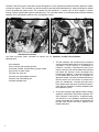
S&S Cycle, Inc.
®
Instruction Sheet 51-1010
Revised 4-4-06
235 Causeway Blvd.
La Crosse, Wisconsin 54603
Copyright®, 2002, 2006
Phone: 608-627-1497 • Fax: 608-627-1488
by S&S Cycle, Inc.
All rights reserved. Printed in the U.S.A.
Technical Service Phone: 608-627-TECH (8324)
Technical Service Email: [email protected]
Website: www.sscycle.com
Because every industry has a leader
Installation Instructions for S&S® TWO THROAT Carburetor
(Serial #E1190 & Higher)
DISCLAIMER:
IMPORTANT NOTICE:
S&S parts are designed for high performance, off road, racing
applications and are intended for the very experienced rider only. The
installation of S&S parts may void or adversely effect your factory
warranty. In addition such installation and use may violate certain
federal, state, and local laws, rules and ordinances as well as other laws
when used on motor vehicles used on public highways, especially in
states where pollution laws may apply. Always check federal, state, and
local laws before modifying your motorcycle. It is the sole and exclusive
responsibility of the user to determine the suitability of the product for
his or her use, and the user shall assume all legal, personal injury risk and
liability and all other obligations, duties, and risks associated therewith.
Statements in this instruction sheet preceded by the following words
are of special significance.
The words Harley®, Harley-Davidson®, H-D®, Sportster®, Evolution®, and
all H-D part numbers and model designations are used in reference only.
S&S Cycle is not associated with Harley-Davidson, Inc.
SAFE INSTALLATION AND OPERATION RULES:
Before installing your new S&S part it is your responsibility to read and
follow the installation and maintenance procedures in these
instructions and follow the basic rules below for your personal safety.
● Gasoline is extremely flammable and explosive under certain
conditions and toxic when inhaled. Do not smoke. Perform installation
in a well ventilated area away from open flames or sparks.
● If motorcycle has been running, wait until engine and exhaust pipes
have cooled down to avoid getting burned before performing any
installation steps.
● Before performing any installation steps disconnect battery to
eliminate potential sparks and inadvertent engagement of starter while
working on electrical components.
● Read instructions thoroughly and carefully so all procedures are
completely understood before performing any installation steps.
Contact S&S with any questions you may have if any steps are unclear
or any abnormalities occur during installation or operation of
motorcycle with a S&S part on it.
WARNING
Means there is the possibility of injury to yourself or others.
CAUTION
Means there is the possibility of damage to the part or motorcycle.
NOTE
Other information of particular importance has been placed in italic type.
S&S recommends you take special notice of these items.
WARRANTY:
All S&S parts are guaranteed to the original purchaser to be free of
manufacturing defects in materials and workmanship for a period of
twelve (12) months from the date of purchase. Merchandise that fails
to conform to these conditions will be repaired or replaced at S&S’s
option if the parts are returned to us by the purchaser within the 12
month warranty period or within 10 days thereafter.
In the event warranty service is required, the original purchaser must
call or write S&S immediately with the problem. Some problems can be
rectified by a telephone call and need no further course of action.
A part that is suspect of being defective must not be replaced by a
Dealer without prior authorization from S&S. If it is deemed necessary
for S&S to make an evaluation to determine whether the part was
defective, a return authorization number must be obtained from S&S.
The parts must be packaged properly so as to not cause further damage
and be returned prepaid to S&S with a copy of the original invoice of
purchase and a detailed letter outlining the nature of the problem, how
the part was used and the circumstances at the time of failure. If after
an evaluation has been made by S&S and the part was found to be
defective, repair, replacement or refund will be granted.
ADDITIONAL WARRANTY PROVISIONS:
● Consult an appropriate service manual for your motorcycle for correct
disassembly and reassembly procedures for any parts that need to be
removed to facilitate installation.
(1) S&S shall have no obligation in the event an S&S part is modified by
any other person or organization.
● Use good judgement when performing installation and operating
motorcycle. Good judgement begins with a clear head. Don't let
alcohol, drugs or fatigue impair your judgement. Start installation
when you are fresh.
(2) S&S shall have no obligation if an S&S part becomes defective in
whole or in part as a result of improper installation, improper
maintenance, improper use, abnormal operation, or any other misuse
or mistreatment of the S&S part.
● Be sure all federal, state and local laws are obeyed with the
installation.
● For optimum performance and safety and to minimize potential
damage to carb or other components, use all mounting hardware that
is provided and follow all installation instructions.
(3) S&S shall not be liable for any consequential or incidental damages
resulting from the failure of an S&S part, the breach of any warranties,
the failure to deliver, delay in delivery, delivery in non-conforming
condition, or for any other breach of contract or duty between S&S and
a customer.
● Motorcycle exhaust fumes are toxic and poisonous and must not
be inhaled. Run motorcycle in a well ventilated area where fumes
can dissipate.
(4) S&S parts are designed exclusively for use in Harley-Davidson® and
other American v-twin motorcycles. S&S shall have no warranty or
liability obligation if an S&S part is used in any other application.
The S&S® Two-Throat series carburetor has been designed for all size displacement Harley-Davidson® Sportster® models
and big twin engines. The carburetor is of the fixed main jet type with fixed intermediate jets, fixed intermediate air bleeds
and an adjustable idle mixture screw. The carburetor has two individual 15/8" throats, each of which supplies a cylinder
through a special manifold with separate induction tracts. The carburetor utilizes an accelerator pump to improve throttling
response and a conventional choke to aid in cold weather starting.
Shovelhead Installation
Sportster® Model Installation
The S&S Two-Throat series carburetor kit contains the A. Sportster® and Big Twin Installation
following items:
One carburetor.
One air cleaner with mounting bracket.
One intake manifold, insulator block, gaskets & bolts.
One fuel line and two clamps.
Two extra sets main jets.
Two extra sets intermediate air bleeds.
One extra sets intermediate jets.
One bowl overflow hose.
1. The old carburetor and manifold must be removed
and the manifold supplied with the kit installed. If the
carburetor is to be used on a knucklehead or
panhead, a bracket is furnished that bolts to the
center crankcase stud and the bottom front manifold
bolt. When this bracket is used, the bottom front
manifold bolt supplied is 1/8" longer and must be used
in the bottom front hole only. For installation on
Sportster® models, a bracket is furnished that bolts to
the front intake cam stud and the air cleaner back
plate. On shovelheads, a bracket that bolts to the
front cylinder rocker box cover and the back plate is
used. After the manifold is installed, temporarily bolt
the carburetor in place.
2. A two cable "pull-pull" type throttle handle assembly
should be used with the Two-Throat carburetor. This
S&S carburetor is fitted with an accelerator pump,
and because of the additional mechanical pump
linkage, the throttle arm assembly has provisions for
the two cable system to insure a positive on-off
throttle movement.
2
WARNING
We do not recommend the use of this carburetor with
the single cable throttle assembly. In the interest of
operator safety, we strongly urge installation of a twocable throttle. The 1981 and later Harley-Davidson®
throttle handle assembly can be adapted for use, or if
one chooses, S&S® Cycle, Inc. can provide or
reasonably price a high quality two cable assembly with
extra long 48" cables. (Complete S&S two-cable throttle
assembly is Part #11-0279).
a. The stock throttle on 1981 and later models
can be adapted by soldering the last 11/2 of
inner cable before cutting the ball or barrel
fitting off the end. The soldering is done to
prevent the strands from separating. Once
this operation is done, remove the carburetor
and feed the cables through the appropriate
bosses on the carburetor. The cable with the
larger diameter outer housing is used to
close the throttle and should be positioned in
the bracketed housing, Part #11-2239, which
is attached to the bowl. When rotating the
throttle handle counterclockwise, looking at
the end of the handlebar, the throttle will
open if the cables are correctly routed. A little
freeplay should be left in both cables when
tightening the throttle arm cable clamp set
screws. Any excessive play can be adjusted
out at the throttle grip cable adjusters before
engine startup.
b. If the S&S two cable throttle handle assembly
is used, the procedure for installation is much
the same except the outer cables are 48" long
and are both of the same diameter. This
means you may have to shorten the outer
cables if they are too long for your particular
installation Determine the best routing for the
outer cables then clip the ends at the
carburetor once you have determined the
correct length. If you shorten the outer cables,
you must also shorten the inner cables, but be
sure to determine the proper length and
resolder the last 1-11/2" of inner cable before
cutting. This will insure the cable strands do
not separate. Apply a light coat of lubrication to
the inner cables and complete the installation.
NOTE - After all cable adjustments are made, work the
throttle several times while turning the handlebars to
extreme right and left before engine startup to be sure the
throttle is snapping off and closing shut all the way. If the
throttle fails to snap shut or close all the way, determine
the cause and correct before engine startup.
NOTE - A thin coating of light grease should be applied to
the throttle arm cam, Part #11-2248, where it contacts the
transfer arm, Part #11-2277, to insure minimized friction
and smooth throttle operation. This grease is necessary
only for the Iast two weeks or so of operation until a
smooth wear pattern is established. Do not lubricate the
pump pushrod, Part #11-2267
3. After installing the throttle assembly, bolt
the carburetor in place using the allen head
bolts provided.
NOTE - For installation on big twins, the stock wire fuel
line bracket should be used to position the fuel line
between the cylinders.
4. The fuel line supplied should be used in place of
the stock line. For Sportster® models, the line is
bent sharply to the rear of the bike over the
carburetor and then around to the inlet fitting on the
bowl. Secure the line on both ends with the
clamps. The fuel line on big twins can normally be
routed between the cylinders. Check or leaks
before starting the engine.
WARNING
Some bikes are equipped with exhaust systems that
curve around the gear cover directly under the
carburetor. The fuel line must not touch the pipe or
be placed in a position where it is exposed to
extreme heat.
NOTE - We strongly suggest that an in-line fuel filter be
used and spliced into the fuel line to keep foreign material
out of this carburetor. With the small metering holes used
in the intermediate system and the accelerator pump
nozzles, it is wise to insure against contamination to
provide trouble free operation.
5. The Two-Throat carburetor features a bowl
overflow system. In the event the rider forgets to
shut off the fuel petcock and the needle and seat
assembly sticks, the excess fuel will flow out
through the overflow hose rather than fill the
cylinders with fuel. For Sportster® model
installations, the hose should be routed between
the front cylinder pushrod covers and down
between the crankcase and generator. For big twin
installations, the hose should be routed between
the rear cylinder pushrod covers and down
between the crankcase and transmission.
3
WARNING
Remember, however, the bowl overflow system is a
safety aid only, and does not mean you do not have to
turn off the fuel petcock. Always turn off the fuel
petcock when the engine is not running.
6. With the fuel line in place, the air cleaner backplate
and mounting bracket can be installed.
NOTE - Before installing the air cleaner backplate, Part
#17-0280, be sure any flash is removed from the formed
holes, especially the bowl vent hole which is positioned
between the air horns just below the middle top mounting
screw hole, and the small drain hole positioned near the
middle bottom of the backplate. The bowl vent hole
matches up with a hole in the carburetor body. If this hole
is blocked or restricted, the carburetor will not run properly.
a. The Sportster® model bracket bolts to the
front intake cam cage stud and to the front
die-cast hole in the air cleaner backplate.
The shovelhead bracket bolts to the hole in
the front rocker box cover just to the rear of
the front intake pushrod and the die cast hole
in the backplate which is positioned closer to
the front airhorn.
b. Before final tightening of the manifold clamps
and mounting bracket, visually check the
motorcycle from the front to insure the carburetor
is horizontal when the bike is held upright.
c.
Immerse the foam portion of the air cleaner
element in a light weight engine oil and squeeze
out. Before final assembly of the air cleaner,
check the needle and seat for possible leakage.
Hold the motorcycle level and turn the fuel
petcock on. If gas does not leak out of the end of
the carburetor bowl overflow hose after 10
seconds, the element and air cleaner cover can
be installed. The chrome wire mesh screen must
be bent to a smooth curve and inserted in the
front of the air cleaner cover. If the needle and
seat do not hold, the bowl should be removed
and checked. See the "General Information"
section of these instructions for details.
7. Special instructions for engines equipped with
breather vent line to the air cleaner.
a. S&S® air cleaners have a special boss cast into
the air cleaner backplate designed especially
for this vent. The backplate should be drilled
and tapped for a 1/8" pipe nipple. This can be
procured at most any hardware store. After the
air cleaner backplate modification is done, the
vent line should be secured with a clamp.
B. Starting Procedure
This carburetor has a conventional choke type starting
mechanism. It has a tension spring, Part #11-2144, that
constantly applies pressure against the choke lever,
Part #11-2246, so that it will remain in position once
set. The choke plates, Part #11-2273, are fully closed
when the lever is pulled up to the stop. The S&S TwoThroat carburetor also has an accelerator pump which
will squirt a stream of fuel directly into each manifold
opening when the throttle is opened quickly.
1. Cold Starts
a. One may use the accelerator pump to prime a
cold engine rather than the full choke method.
Wait for 10 seconds after turning on the fuel
petcock and then prime the engine by giving
two quick wide open throttle movements. Then
kick with the choke in the 2/3 closed position
and the throttle slightly opened. But be careful
as it is easy to flood the engine with the
accelerator pump. If you think the engine is
flooded, open the throttle slowly to the wide
open position. By opening the throttle slowly
the pump is not actuated. Also open the choke
and then kick through until the engine starts or
the flooded condition is cleaned out.
b. During our extensive testing with this
carburetor, we eventually got to the point
where we rarely used the choke, normally
accomplishing most cold starts by priming with
the pump only.
c.
4
Motors will react differently due to the type of
cams or pipes, etc. and you will have to
experiment with your particular bike until you
find the best starting procedure for your own
set of circumstances.
2. Hot Starts
1. Hot starting does not normally require the use
of the choke or pump priming. Starting is
usually accomplished by turning on the ignition
and kicking with the throttle closed.
3. Electric Start Model
CAUTION
Never close the idle mixture screw tightly as damage to
the needle and seating area in the carburetor body may
result. The throttle stop engine RPM adjustment screw
located on the throttle arm, Part #11-2248, is initially
set by holding the throttle closed and turning the
screw until it contacts the throttle arm stop boss. At
this point it is turned an additional 1/2 turn clockwise.
b. Start the engine and warm it up to operating
temperature. Adjust the engine RPM to a slow
idle, approximately 800 RPM. Then turn the
idle mixture screw in, leaning it, until the
engine starts to die. Next, turn the screw back
out, richening it, until it starts to die. A position
about halfway between these points, or a
setting of about 1/2 a turn out from the lean side
of the range is the correct setting. From the
fully closed position this would be
approximately 2 to 3 turns. Then reset the
throttle stop screw to give final desired RPM
idle speed. Idle speeds will vary according to
the individual and the use to which the
machine is put.
a. Close the choke halfway, turn on the ignition,
and with the throttle slightly cracked engage
the starter. After the engine starts, open the
choke and work the throttle slightly until the
engine will idle.
Trouble Shooting Tips
Engine will not start:
●
●
Fuel supply empty or restricted.
Weak or no spark - discharged battery or faulty
magneto.
NOTE - We do not recommend tho use of magnetos.
●
●
●
●
●
●
Plug gap too wide - we use .020 to .022 plug gap
on our point type ignition engines.
Improper ignition timing.
Tight tappet adjustment.
Improper idle mixture and/or engine RPM setting.
Intermediate jets or air bleeds loose.
Improper diagnosis of a rich or lean mixture
condition. If the engine fires in the carb, it is too
lean and must be re-primed. Do not continue to
kick the engine over with the switch on until it is
reprimed. If there is no response after three kicks
or if it pops in the exhaust pipes, it is too rich.
Leave the switch on and open the throttle wide
open and kick until it fires.
C. Adjusting the Carburetor
1. Idle Circuit
a. The idle mixture screw, Part #11-2354, is
initially set during assembly to 21/2 turns out
from the fully closed position. Check this and
reset the screw to 21/2 turns before attempting
to start the engine.
NOTE: Whenever an intermediate system jetting change
is made, the idle mixture screw should be readjusted with
the engine hot.
Trouble Shooting Tips
Engine will not idle.
●
●
●
Improper idle mixture and/or engine RPM setting.
Intake manifold air leak.
Sticky timing automatic advance mechanism.
NOTE - On those engines with spring loaded mechanical
advance ignition systems, we perform as standard
procedure to each of our motors, the following
modification: Remove and clean the timing advance
mechanism. Rebend the small springs which retard the
timing by shortening each spring 1/16" on both ends to
increase spring tension. This will insure the engine retards
properly and returns to a smooth, low idle. We have found
that this normally cures those conditions where the motor
will not always return to a low idle and instead sometimes
idles at a higher speed, up to 1400-1600 RPM .
●
●
Foreign material obstructing gas flow to idle circuit.
Incorrect intermediate jetting.
5
2. Intermediate System
Up to 3000 RPM or 55-60 MPH
a. For normal riding conditions, the intermediate
range is used the most. Therefore, close
attention must be paid to jetting the mid-range
to achieve optimum performance and gas
mileage. Once the engine is warmed up and
the idle mixture and engine RPM screws set,
the bike must be road tested. The intermediate
range is used from right off idle up to
approximately 3000-3500 RPM or 50 to 60
MPH depending on gearing. Throttling
characteristics can be checked by slowly
opening the throttle (so as to not energize the
accelerator pump) after maintaining a steady
speed. This can be done at several RPM levels
or speeds of 30, 40, and 50 MPH. If popping or
spitting occurs in the air cleaner, this is a lean
condition and should be corrected. Another
indication of a lean intermediate system can be
noticed by feeling a "flat" or "laboring"
condition while cruising at 55 to 60 MPH, right
at the top of the intermediate range.
NOTE - As mentioned earlier, it is extremely critical that
the idle mixture screw and throttle stop screw be adjusted
with a hot motor. The idle will effect the intermediate
system and if it is not adjusted properly, one will not get a
true reading as to the performance of the intermediate.
b. If the intermediate system is too rich, it may
show up by popping in the pipes, a "lope" or
miss at lower RPMs, or a miss or stutter at
transition, about 3000 to 3500 RPMs, especially
in low gear under reduced load conditions.
c.
To lean the intermediate, install a smaller set of
intermediate jets, Part #11-7300. One may also
make subtle changes by bleeding in more air by
installing larger air bleeds, Part #11-7320.
d. To richen the intermediate system, install a
larger pair of intermediate jets and/or smaller
air bleeds
NOTE - A properly jetted intermediate system will act lean
(cough or spit) when the engine is cold and will require riding
a few miles to warm the engine to operating temperature.
6
e. Higher altitude or hot, dry weather may require
a leaner mixture (smaller intermediate jets
and/or bigger air bleeds) while lower altitude,
cold weather, or a warm and humid climate
may require a richer mixture (larger
intermediate jets and/or smaller air bleeds) to
dial the system in properly.
f.
We have run a:
1. 900cc Harley-Davidson® Sportster® model
with the .029-.046 intermediate combination.
2. 1000cc Sportster® model with .030-.046.
3. Stock 74" panhead with .029-.046.
4. 80" shovelhead with .030-.046.
5. 98" shovelhead with the .033-.046
combination.
3. Main Jet
From 3000 RPM or 55-60 MPH and up:
a. Main jetting is best determined by testing at the
drag strip. Jetting should always be done at
operating temperature. After a run is made, the
engine RPM and final speed should be noted.
A second run should be made with a .004
larger, richer, jet installed. Again, RPM and
final speed is noted. This procedure should be
continued until the miles per hour falls off. The
main jet should then be made smaller (leaner)
to gain the best maximum RPM and MPH.
When making these runs, do not strive for ETs,
but for consistent miles per hour. We have
found that maximum miles per hour and RPM
have been the best indicators of proper jetting.
b. If the engine is buttoned off after each run, the
spark plugs may be inspected for richness or
leanness. Plug color though is not always a
good indication of carb jetting on quarter mile
tests. We have found that different brands of
gasoline, gasoline additives, engine heat (due
to ignition timing), and type of plugs and heat
range used alter readings drastically. New
plugs usually require the time involved in a
road test to properly develop the plug color. It
is best to use a proven combination and to
consult the spark plug manufacturer for more
specific information if one desires to become
proficient at plug reading. Champion Racing
Division has a very informative booklet. For
details, write:
Champion Spark Plug Company
P.O. Box 910
Toledo, Ohio 43601
c.
If main jetting tests cannot be conducted at the
drag strip, the "RPMing" method can be used.
This procedure would be to run the bike
through the gears noting how quickly and
smoothly the engine reaches the RPM level
where gears are shifted. Under racing
conditions this level is where horsepower
peaks and begins to taper off. The main jet that
makes the engine pull the strongest or RPM
through the gears best is the correct one. Our
experience is that a jet about .006 smaller
(leaner) in size will make the engine pop and
sputter or "break up" in the carburetor and die.
A jet about .006 larger (richer) will make the
engine run flat and sluggish or "blubber".
d. On certain engines, particularly Sportster®
models, an indication of a rich main jet
condition will sometimes appear as a slight
miss at transition from the intermediate system
to the main jets.
e. If this occurs while running hard through the
gears at 3000-4000 RPM, try smaller main jets.
f.
We
1.
2.
3.
4.
5.
have run:
900cc Sportster® models with .050 main jets.
1000cc Sportster® models with .052's.
Stock 74" panhead with .050's.
80" shovelhead with .052's.
98" shovelhead with .056's.
Trouble Shooting Tips
Engine will not run at steady speed:
●
●
●
●
●
●
Restriction in fuel supply system - gas tank vent
plugged, gas petcock too small (stock HarleyDavidson® petcock is adequate, but might require
running on reserve to provide adequate supply for
big inch engines), needle and seat assembly not
working properly.
Faulty ignition system - fouled plugs, worn points,
defective coil.
Incorrect intermediate and/or high speed jetting.
Foreign material in air and/or gas passageway in
carb causing flow restriction. Remove and clean
intermediate jets and bleeds.
Valve train defect - bad valves, sticky valves,
bad or broken springs, improper clearances for
high lift cams.
Bowl vent obstructed.
Engine
●
●
●
●
will not RPM:
Restriction in fuel system.
Faulty ignition system.
Incorrect high speed jetting.
Foreign material in air and/or gas passageways in
carb causing flow restriction.
● Too much gear. (Not enough horsepower to pull
the gearing.)
● Valve train defect.
● Bowl vent obstructed.
g. The above was warm weather jetting at 600 to
1000 feet above sea level elevation.
h. Obviously, like the intermediate jetting, the
main jet requirements will vary somewhat
with conditions.
7
D. General Information
1. Do not chrome the carburetor as extensive
damage will result.
Top
Bevels must
be at angles
shown when
installing
throttle plate.
2. The carburetor has several drilled passages that
are permanently sealed with plugs. Do not attempt
to remove these plugs.
3. Do not over-tighten the idle mixture screw,
intermediate jets, or intermediate air bleeds.
Side View
4. The throttle plates. Part #11-2255, and throttle
shaft, Part #11-2254, should be checked annually
for signs of wear. Replace, if necessary. If they are
removed, be sure that the throttle plates are
reinstalled correctly. See Figure A.
5. If the throttle arm, Part #11-2248, is removed from
the throttle shaft, it must be reinstalled in the wide
open position with the butterfly at 90° to the fully
closed position. See Figure B.
6. The correct float level adjustment is shown below in
Figure C. When the motorcycle is not running, the
fuel shutoff valve should always be turned of. In the
event fuel runs out of the bowl overflow hose,
remove the bowl assembly and inspect the float and
needle and seat assembly to be sure it doesn’t bind
and the float level is properly set. See Figure C.
7. If an air cleaner other than ours must be used,
make sure the bowl vent hole in the inlet end of the
carburetor is not covered and sealed off.
Figure A
8. Cams and exhaust systems make some engines
difficult to carburate. A combination of cam overlap
and back pressure, or lack of back pressure will
cause mixture dilution at certain engine RPMs.
This dilution will cause engine roughness or
misfiring when the engine is held in this range. To
attempt to carburate for this condition usually
destroys the carburetion over the rest of the range.
It is best under these conditions to change the cam
and/or the exhaust system.
9. S&S® has found that stock head pipes equipped
with a good quality slip-on muffler will provide a
nice amount of horsepower and torque.
10. Use a fuel filter to keep dirt out of this carburetor.
With the small metering holes used in the
intermediate system and the accelerator pump
nozzles, it is wise to insure against contamination
to provide trouble free operation.
Throttle plate
horizontal
Throttle arm
against stop
Throttle arm
set screw
Side View
Figure B
8
Bowl is shown upside down.
Side View
Figure C
11. For those involved in an "all-out" drag racing effort
using very large displacement engines, you may
consider:
a. Raising the float level 1/8",
b. To improve air-flow, removing the choke
assembly and plugging the choke shaft holes
in the carb body as well as running without the
air cleaner element. You may also elect to run
the 1" spacer block, Part#16-0295, and do
some porting work to the induction tract to
further improve air flow.
12. In closing, remember that this carburetor has large
venturi compared to the stock unit. This means that
at low RPMs, velocity through the carburetor is
very low and it is more difficult to energize the main
jet, particularly on stock displacement big twin or
Harley-Davidson® Sportster® models. Because of
the design and with the addition of an accelerator
pump. one can generally "whack" the throttle on at
lower RPMs and still pick up the main jet. With our
stock l000cc Sportster, we were able to "whack it
on" at 1200 RPM in low, 1600 RPM in second,
2000 RPM in third and 2500 RPM in high. Below
those RPMs, we either down-shifted or slowly
rolled the throttle on until RPMs were up sufficiently
to pick up the main jet. After getting your particular
engine jetted properly, you will have to experiment
with the throttling characteristics as this will vary
with different motor configurations.
E. Jetting Tips
3. The idle mixture screw, Part #11-2354, is located on
the top of the carburetor. Turning the screw clockwise
(in), will lean the mixture. A counterclockwise motion
(out), will richen the mixture.
4. The intermediate jets, Part #11-7300, are available
in sizes from .028 to .034 in graduations of .001
with .034 being the richest. Normally, .029 to .033
sizes are used.
5. The intermediate air bleeds, Part #11-7320, are
made in sizes .028, .032, .036, .040, .043, .046,
.052, .055, .059, and .063, with .063 being the
leanest. Normally bleeds in the middle of the scale
will be used.
6. The main jets, Part #11-7200, are made in
increments of .002 and range in size from .040 to
.060, with .060 being the richest. They can be
changed after removing the bottom bowl plugs.
7. When changing any jets, be sure to change in pairs,
as each throat or "barrel" has its own set of jets.
8. Upon warming the engine to normal operating
temperature after making any jetting changes to the
intermediate system always readjust the idle
mixture screw.
Below is a chart with some basic guidelines to follow while
jetting your Two-Throat carburetor.
1. Use a fuel filter to insure foreign material does not
enter this carburetor.
Mild
Strokers
Large
Engines
61"-74"
80"-84"
86" & up
®
Sportster models
55"-61"
Up to 74"
75" & up
Idle Mixture Screw
2-3 turns
2-3 turns
2-3 turns
Intermediate Jet
.029-.030
.030-.031
.032-.033
Intermediate Bleed
.040-.052
.040-.052
.040-.052
Main Jet
.046-.054
.048-.056
.052-.060
Big Twin
2. The Two-Throat has an adjustable idle mixture
screw, fixed intermediate jets, fixed intermediate air
bleeds and fixed main jets.
Stock
CID
9
Two-Throat Carburetor
Replacement Parts
1.
Choke/throttle plate screw 6-32 x 1/4"
. . . . . . . . . . . . . . . . . . . . . . .11-0055
2.
Idle mixture screw spring . . .11-2052
3.
Idle mixture screw . . . . . . . . .11-2354
4.
Seat . . . . . . . . . . . . . . . . . . .11-2065
5.
Main jet - See "Jetting Chart".
6.
Air cleaner cover screw
(10 Pack) . . . . . . . . . . . . . . . . .50-0094
7.
Throttle return spring . . . . . .11-2082
8.
Back plate-bowl screw with lockwasher
10-24 x 5/8" (10 Pack) . . . . . . .50-0062
43. Choke plate . . . . . . . . . . . . . .11-2273
44. Diaphragm spring . . . . . . . . .11-2275
26. Intermediate jet - See "Jetting Chart".
45. Pump lever . . . . . . . . . . . . . .11-2276
27. Throttle shaft . . . . . . . . . . . . .11-2254
46. Transfer arm . . . . . . . . . . . . .11-2277
28. Throttle plate . . . . . . . . . . . . .11-2255
47. Air cleaner cover . . . . . . . . .17-0278
29. Gasket - manifold . . . . . . . . .16-0256
48. Air cleaner element . . . . . . .17-0279
30. Cover - pump cap . . . . . . . . .11-2257
49. Back plate . . . . . . . . . . . . . . .17-0280
31. "Y" manifold
All Harley-Davidson® Sportster®
models . . . . . . . . . . . . . . . .16-4300
Shovels 1979 & earlier . . . .16-4316
50. Diaphragm . . . . . . . . . . . . . .11-2282
32. Manifold screw - 20 x 13/8"
Shovel, Sportster® models or Pan
(10 Pack) . . . . . . . . . . . . . . . . .50-0153
51. Pump cap . . . . . . . . . . . . . . . . . .N/A
52. Lever screw . . . . . . . . . . . . .11-2285
53. O-ring
(10 Pack)
. . . . . . . . . . .50-8096
54. Bowl . . . . . . . . . . . . . . . . . . . . . . .N/A
55. Gasket, bowl . . . . . . . . . . . . .11-2289
56. Air cleaner screen . . . . . . . .17-0290
10. Needle . . . . . . . . . . . . . . . . .11-2095
33. Manifold screw - 1/4 - 20 x 2"
For use with spacer block. . . . . .N/A
11. Support bracket bolt . . . . . . . . . .N/A
34. Ovorflow hose . . . . . . . . . . . .19-0262
12. Support bracket locknut . . . . . . .N/A
58. Air cleaner support bracket
Shovelhead . . . . . . . . . . . . . . . . .17-0292
13. Choke arm screw . . . . . . . . .11-2143
35. Manifold screw - 1/4 -20 x 11/2"
Bottom front only for panheads . .N/A
14. Choke spring . . . . . . . . . . . . .11-2144
36. Panhead manifold
15. Choke washer
37. Bellows seal . . . . . . . . . . . . .11-2266
16. Intermediate air bleed
See "Jetting Chart".
39. Float screw 10-32 x 1/4" . . . . .50-0036
17. Float . . . . . . . . . . . . . . . . . . . . . . .N/A
40. Float pin . . . . . . . . . . . . . . . .11-2269
18. Cable housing bracket . . . . .11-2339
41. Actuator pin . . . . . . . . . . . . . .11-2271
19. Choke shaft . . . . . . . . . . . . . .11-2246
42. Ball check
9.
Bottom plug . . . . . . . . . . . . .11-2090
20. Body . . . . . . . . . . . . . . . . . . .11-2247
21. Throttle arm assembly . . . . .11-2248
22. Screw with lock washer
6-32 x 5/16 . . . . . . . . . . . . . . . . . . .N/A
23. Main discharge tube . . . . . . .11-2250
10
24. Transfer arm screw . . . . . . . .11-2251
25. Gasket - pump cap cover . . .11-2252
38. Pushrod - pump . . . . . . . . . .11-2267
(10 Pack)
. . . . . . . .50-8125
57. Insulator block . . . . . . . . . . .16-0291
59. Air cleaner support bracket
Sportster® models . . . . . . . .17-0293
60. Pump cap screw lockwasher 8-32 x 7/16"
. . . . . . . . . . . . . . . . . . . . . . . . . . . . . .N/A
61. 1" Spacer block (optional) . .16-0295
62. Air cleaner support bracket - panhead
. . . . . . . . . . . . . . . . . . . . . . .16-0296
32
33
61
31
29
7
13
1
26
27
14
2
16
57
29
32
3
15
36
19
35
1
49
28
62
48
20
23
8
43
56
21
55
5
17
42
44
40
11
39
53
54
58
6
59
50
24
53
10
12
41
46
8
34
34
9
18
37
38
51
45
60
25
30
22
4
11
Because every industry has a leader