1
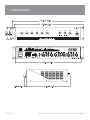
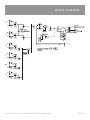
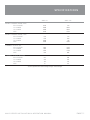
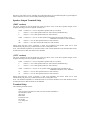
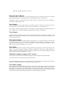
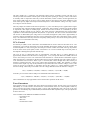
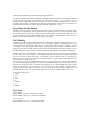
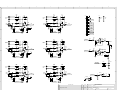
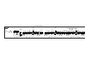
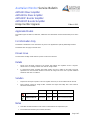
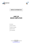
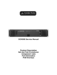
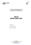
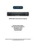
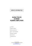
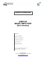
SERVICE INFORMATION
AMIS120
MIXER AMPLIFIER
(6ch version)
CONTENTS:
OPERATION MANUAL
PRODUCT DESCRIPTION
SCHEMATIC DIAGRAMS
BOARD LAYOUTS
SERVICE BULLETINS
* Over the years there have been a
number of revisions to this model
Australian Monitor
1 Clyde Street, Silverwater NSW 2128 Australia
+61 2 9647 1411
www.australianmonitor.com.au
AMIS SERIES
6 0 W / 1 2 0 W M I X E R A M P L I FIER
I N S TA L L AT I O N A N D O P E R AT I O N M A N UAL
I M P O RTA N T SAFETY INFORMATION
1. Save the carton and packing material even if the equipment has arrived in good condition. Should you ever need to ship the unit, use
only the original factory packing.
2. Read all documentation before operating your equipment. Retain all documentation for future reference.
3. Follow all instructions printed on unit chassis for proper operation.
4. Do not spill water or other liquids into or on the unit, or operate the unit while standing in liquid.
5. Make sure power outlets conform to the power requirements listed on the back of the unit.
6.
Do not use the unit if the electrical power cord is frayed or broken.
The power supply cords should be routed so that they are not likely to be walked on or pinched by items placed upon or against them, paying particular attention to cords and plugs, convenience receptacles, and the point where they exit from the appliance.
7. Always operate the unit with the AC ground wire connected to the
electrical system ground. Precautions should be taken so that the
means of grounding of a piece of equipment is not defeated.
13.
Do not block fan intake or exhaust ports. Do not operate equipment on a surface or in an environment which may impede the normal flow
of air around the unit, such as a bed, rug, weathersheet, carpet, or completely enclosed rack. If the unit is used in an extremely dusty
or smoky environment, the unit should be periodically “blown free” of foreign matter.
14. Do not remove the cover. Removing the cover will expose you to potentially dangerous voltages. There are no user serviceable parts inside.
15. Do not drive the inputs with a signal level greater than that required to drive equipment to full output.
16. Do not connect the inputs / outputs of amplifiers or consoles to any
other voltage source, such as a battery, mains source, or power supply,
regardless of whether the amplifier or console is turned on or off.
17.
Do not run the output of any amplifier channel back into another channel’s input. Do not parallel- or series-connect an amplifier output
with any other amplifier output. Australian Monitor Inc is not responsible for damage to loudspeakers for any reason.
18. Do not ground any red (“hot”) terminal. Never connect a “hot” (red)
output to ground or to another “hot” (red) output!
8. Mains voltage must be correct and the same as that printed on the
rear of the unit. Damage caused by connection to improper AC voltage
is not covered by any warranty.
19. Non-use periods. The power cord of equipment should be unplugged
from the outlet when left unused for a long period of time.
9. Have gain controls on amplifiers turned down during power-up to prevent speaker damage if there are high signal levels at the inputs.
20. Service Information Equipment should be serviced by qualified service
personnel when:
10 Power down & disconnect units from mains voltage before making
connections.
A. The power supply cord or the plug has been damaged.
B. Objects have fallen, or liquid has been spilled into the equipment
11. Never hold a power switch in the “ON” position if it won’t stay there itself!
C. The equipment has been exposed to rain
12. Do not use the unit near stoves, heat registers, radiators, or other heat
producing devices.
D. The equipment does not appear to operate normally, or exhibits a marked
change in performance
E. The equipment has been dropped, or the enclosure damaged.
THIS SAFETY INFORMATION IS OF A GENERAL NATURE AND MAY BE SUPERSEDED BY INSTRUCTIONS CONTAINED WITHIN THIS MANUAL
INTRODUCTION AND CONTENTS
The AMIS60 and AMIS120 mixer amplifiers are designed for commercial
installations. Both models operate on 230/240 VAC, 50Hz (115VAC, 60Hz) or
24 VDC, and may be desk or rack mounted (rack mount kit supplied fitted). The
AMIS60 will deliver 60 watts into a load of 8 ohms, 70 volt or 100 volt line.
The AMIS120 will deliver 120 watts into a load of 4 or 8 ohms, 70 volt or 100
volt line. Both Models feature 6 universal mic/line inputs. The AMIS60/120
also feature a dual RCA record output while a balanced XLR output is also
provided to feed external booster power amplifiers. Other standard features
include on-board bell, pre-announce, alert & evac tones, remote master VCA
control & priority muting. As standard, both models are self standing and
come with rubber feet.
INTRODUCTION
3
FRONT PANEL
4
REAR PANEL
5
INSTALLATION
6
SE TUP & TROUBLESHOOTING
7
DIMENSIONS
8
BLOCK DIAGRAM
9
SPECIFICATIONS
10
AUS, EUR, USA
Copyright 21st Mar 2007
Rev A: 21st Mar 2007
This symbol is intended to alert the user to the presence
of uninsulated “dangerous voltage” within the products
enclosure that may be of sufficient magnitude to constitute
a risk of electric shock to persons.
CAUTION
RISK OF ELECTRIC SHOCK
DO NOT OPEN
CAUTION: TO REDUCE THE RISK OF ELECTRIC SHOCK,
This symbol is intended to alert the user to the presence
of important operational and maintenance (servicing)
instructions in the literature accompanying the appliance.
DO NOT REMOVE COVER (OR BACK),
NO USER SERVICEABLE PARTS INSIDE,
REFER SERVICING TO QUALIFIED SERVICE PERSONAL.
Caution:
WARNING!
TO REDUCE THE RISK OF FIRE OR ELECTRIC HOCK
To prevent electric shock do not use this (polarised) plug
with an extension cord, receptacle or other outlet unless
the blades can be fully inserted to prevent blade exposure.
To prevent electric shock, match wide blade of plug to wide
slot, fully insert.
DO NOT EXPOSE THIS EQUIPMENT TO RAIN OR MOISTURE.
A M I S S E R I E S I N S TA L L AT I O N & O P E R AT I O N M A N U A L
PA G E 3
F R O N T PA N E L
1
1
2
3
4
5
6
CH 1-6
These control the individual level for each channel
input.
2
BASS
There is 12dB of cut and boost at 100Hz. This EQ is the
shelving type.
3
TREBLE
There is 9dB of cut and boost at 10kHz. This EQ is the
shelving type.
4
MASTER
This controls the overall output level.
5
ON
This LED indicates the unit is powered “on”.
NOTE: When using the “24VDC” in terminals, the amplifier is ‘on’ and the power LED will always be on regardless of the position of the power switch.
6
POWER
This switch switches power on or off from the
mains. The up position is on.
NOTE: When using the “24VDC” in terminals, the amplifier is ‘on’ regardless of the switch position.
PA G E 4
A M I S S E R I E S I N S TA L L AT I O N & O P E R AT I O N M A N U A L
R E A R PA N E L
11
10
1
4
7
12
3
CH 1-6
Each channel input section has two inputs:
XLR input – This is a balanced microphone input. It has an
input sensitivity of 1mV.
RCA input – This is an unbalanced line level input. It has
an input sensitivity of 150mV. The two RCA sockets are
summed to mono internally.
2
REC OUTPUT
The REC output is on unbalanced RCA connectors. The
output level is 300mV into 10kohm at rated output. The
output is dual mono.
The REC output is not affected by the MASTER volume
control or the BASS and TREBLE controls. The REC output
does not receive the tone signal.
3
LINE OUTPUT
The LINE output is on a balanced XLR connector. The output level is 2V into 1k at rated output. NOTE: When wiring the LINE output as unbalanced, Pin2 should be wired as hot and Pin1 should be wired as ground/shield. Do not wire Pin3.
4
AMP OUT
The speaker connections are on the 12 pole terminal strip.
There is a low impedance output (OHM) and a distributed
line voltage output (LINE).
25V/70V out is available on 115V models.
70V/100V out is available on 230V/240V models.
8ohm out is available on the AMIS60 and AMIS120.
4ohm out is available on the AMIS120.
MINIMUM IMPEDANCE
Distributed Line Output
AMIS60
AMIS120
25V (115V version) 10.4ohm 5.2ohm 100V (230/240V version) 333ohm 166ohm
70V (230/240 & 115V versions) 166ohm 83ohm Low Impedance Output
4 ohm (230/240 & 115V versions) N/A 4ohm 8 ohm (230/240 & 115V versions) 8ohm
8ohm
NOTE: Only connect one output - either Distributed Line or Low Impedance per channel. Do not connect the 8ohm, 4ohm and 100V at the same time.
The output strip comes fitted with a touch-proof cover held
in place by two M3 machine screws with flat and spring
washers.
9
6
5
8
2
5
1
VCA CONTROL
These two terminals provide connection for an external
potentiometer (500k log) which is available mounted on
a wall panel from Australian Monitor (RC1). When the
potentiometer is connected it allows for remote control
of the master level. The external pot is governed by the
master level of the amplifier allowing the installer to set
the volume and then lock the amplifier in a rack, leaving
the user with just a master volume control that cannot go
beyond the level set on the front panel master control. The terminals can also be used as a system mute by
shorting the two contacts together (by a relay or switch
for example).
6
VOX RELAY
These terminals provide connection for the priority relay
output. The relay outputs are C (Common), NO (Normally
Open) and NC (Normally Closed). These are the states of
the relay when the amplifier is off (mains or dc). When
the unit is switched on the relay activates. The relay
deactivates when signal is present at any of the priority
inputs regardless of the front panel channel volumes. This
would normally be inputs 1 and 2 however these channels
can be removed from the priority bus via internal links
(see “Functional Notes’). The unit is shipped from the
factory with inputs 1 and 2 having priority so assuming
that this has not been changed, signal at any of these
inputs will deactivate the VOX relay circuit. The relay also
deactivates when a tone sound is triggered
The NO or NC selection provides the installer with the
option of the relay either opening or closing a contact.
This feature is normally used in conjunction with relay
override attenuators (volume controls). In this application,
the relay output could trigger an accessory power supply
which in turn bypasses the remote attenuators. The result
is that priority inputs or alarm tones will always be heard
irrespective of the attenuator setting. The relay contacts
are rated at 3 amps at 125VAC/30VDC.The relay can be
disabled via an internal link (see “Internal Settings”).
7
TONES MODULE
These terminals provide connection for triggering the
in built tone module. The four tones can be activated
individually by shorting the named terminal to COM. When
any tone is activated, all inputs (except for inputs 1 and
2) will automatically mute. The level of the tones can by
adjusted internally (see “Internal Adjustments”). The pot
adjusts the level for all 4 tones.
A M I S S E R I E S I N S TA L L AT I O N & O P E R AT I O N M A N U A L
Tones available on the AMIS60 and AMIS120 are:
- Evacuation Tone
- Alert Tone
- Bell Tone
- Pre-Announce Chime
8 TELEPHONE INPUT (only on 115V models)
The 600 ohm transformer balanced Telephone Input is
paralleled with input 2. If telephone paging is required,
the XLR & dual RCA inputs should not be used as these
inputs will be summed with the Telephone Input into channel 2. The front panel level control will set the gain
for the Telephone Input.
The Telephone input is shipped with a jumper lead connected to the input terminals; this must be discarded if the telephone input is to be used. 9 24VDC POWER IN
These terminals provide connection for an external 24V
emergency power system and are not switched by the
front panel power switch. The 24VDC in does NOT provide
any trickle charge facility. The binding posts can accommodate wire of up to 1.5mm in diameter. The
maximum current draw at 24VDC is 9A.
10 IEC MAINS INPUT SOCKET
This is a standard IEC 3 pin socket. It accepts a standard
IEC mains cable, provided. The fuse draw contains the
mains fuse and a spare.
AMIS60
AMIS120
230V/240V model
2A
3.15A
115V model
3.15A
4A
IMPORTANT: Always replace the fuse with one of the same value and type.
NOTE: Always disconnect power to the amplifier before replacing fuses.
11 VOLTAGE SELECT SWITCH (only on 230V/240V models)
This switch is used to select the mains voltage for your
region.
IMPORTANT: Disconnect power to the amplifier
before operating this switch.
12 PHANTOM POWER
This switch enabes +15V phantom power across all XLR
input connectors.
PA G E 5
I N S TA L L AT I O N
MOUNTING
OUTPUT CONNECTIONS
When rack mounting, it is advisable to allow 1 rack space above and below
the amplifier. When multiple amplifiers are mounted in a rack, exhaust fans
should be used on the rack. Airflow for cooling the amplifier is by convection from bottom to top and by fan left to right.
The output terminal strip accepts wire sizes from 16-22AWG (1.5mm2 - 0.35mm2).
The following table should be used as a guideline for cable sizes. Regulations in your area may require different gauged wire and should be checked
before using.
OUTPUT DISTANCE WIRE SIZE
AMC60 100V Up to 50m AWG26(0.12mm )
AWG24(0.2mm2)
50m–200m AWG20(0.5mm2)
AWG18(0.75mm2)
Over 200m AWG18(0.75mm2)
AWG16(1.5mm2)
70V Up to 50m AWG24(0.2mm2)
AWG22(0.35mm2)
50m–200m AWG18(0.75mm2)
AWG16(1.5mm2)
Over 200m AWG16(1.5mm2)
AWG13(2.5mm2)
4 ohm Up to 10m AWG20(0.5mm2)
AWG20(0.5mm2)
10m–30m AWG16(1.5mm2)
AWG16(1.5mm2)
Over 30m Not Recommended Not Recommended
8 ohm Up to 10m AWG24(0.2mm )
AWG24(0.2mm2)
10m–30m AWG18(0.75mm2)
AWG18(0.75mm2)
Over 30m Not Recommended Not Recommended
AMC120
2
2
230/240V version
NOTE: Only connect one output - either Distributed Line or Low Impedance.
The LINE output XLR can be used to connect up to 6 booster amplifiers.
Balanced input wiring (shielded pair cable) is recommended.
115V version
Both versions
PA G E 6
NOTE: When wiring the LINE output as unbalanced, Pin2 should be wired as hot and Pin1 should be wired as ground/shield. Do not wire Pin3.
The REC output wiring should be kept as short as possible.
INPUT CONNECTIONS
For wiring balanced in, pin 2 is hot. Unbalanced wiring on the microphone inputs is not recommended. Balanced input wiring (shielded pair cable) is recommended.
Unbalanced RCA wiring should be keep as short as possible.
A M I S S E R I E S I N S TA L L AT I O N & O P E R AT I O N M A N U A L
SETUP & TROUBLESHOOTING
Levels
Volume controls should aimed to be set at nominal, which is at the half or 12o’clock position. Any unused channels should be set to minimum.
When establishing a mix, remember: Less is more.
TROUBL E S H O O T I N G G U I D E
TROUBLE
LIKELY CAUSE
REMEDY
Power LED not on
Power not reaching amplifier
Check mains connection
Check mains fuse
Check power switch is on
Distorted sound
Output is short circuit Input is overloaded Output is being over driven Bass control is turned up Check speaker loads for shorts
Reduce input level at source
Reduce volume levels on front panel
Reduce Bass control level
No sound but amp is on
DC fuse(s) blown
Volume controls down
Amplifier has overheated
Refer product to local Australian Monitor dealer
Check volume controls
Make sure the amplifier is
well ventilated.
No sound from channels 3-6 Priority function is being used Remove signal (disconnect input) from channel 1 OR
Disable priority function (see Internal Adjustments)
Condenser microphone does not work Phantom power not switched on
Turn on phantom power switch on back panel.
PRIORITY
Channel 1 and 2 are set up to mute channels 3 to 6. This
will only occur when signal appears on channel 1 or 2
irrespective of the channel volume control.
Priority can be disabled. (See below).
The release time is approx. 1 sec and is NOT adjustable.
The mute depth is greater than 60dB and is not adjustable.
A M I S S E R I E S I N S TA L L AT I O N & O P E R AT I O N M A N U A L
PA G E 7
DIMENSIONS
PA G E 8
A M I S S E R I E S I N S TA L L AT I O N & O P E R AT I O N M A N U A L
BLOCK DIAGRAM
A M I S S E R I E S I N S TA L L AT I O N & O P E R AT I O N M A N U A L
PA G E 9
S P E C I F I C AT I O N S
AMIS 60 AMIS 120
POWER OUTPUT (0.5%THD, 1KHZ) 60W 120W
S/N RATIO > 76dBr
> 76dBr
60Hz-15kHz
60Hz-15kHz
POWER BANDWIDTH (-3DB +1DB) OUTPUT REGULATION 90%
90%
SIZE (WXHXD) 482x88x313.5mm
19”x3.5”x12.3”
482x88x313.5mm
19”x3.5”x12.3”
8.5kg
18.7lb 11.0kg
24.2lb
525x175x385mm 20.7”x6.9”x15.2”
525x175x385mm
20.7”x6.9”x15.2”
10.5kg 23.1lb
13.0kg
28.6lb
NET WEIGHT SHIPPING DIMENSIONS (WXHXD) SHIPPING WEIGHT COMMON TO ALL MODELS
THD (1KHz, -1dB) < 0.5%
MIC INPUT SENSITIVITY IMPEDANCE HEADROOM 1mV
1k3 ohm
136mV (42dB)
AUX INPUT SENSITIVITY IMPEDANCE HEADROOM 50mV
>200kohm
> 15V (>40dB)
TONE CONTROLBASS @ 100HZ TREBLE @ 10KHZ LINE OUT
+/- 12 dB
+/- 9 dB
SENSITIVITY OUTPUT IMPEDANCE 2V @ 1kohm
100ohm
TAPE SENSITIVITY
OUTPUT IMPEDANCE 300mV @ 10kohm
100ohm
PA G E 1 0
A M I S S E R I E S I N S TA L L AT I O N & O P E R AT I O N M A N U A L
S P E C I F I C AT I O N S
AMIS 60 AMIS 120
MAINS CURRENT DRAW (240V)
FULL POWER 1/3 POWER 1/8 POWER IDLE 0.75A
0.50A
0.40A
0.25A
1.5A
0.95A
0.65A
0.15A
MAINS CURRENT DRAW (115V)
FULL POWER 1/3 POWER 1/8 POWER IDLE 1.6A
1.0A
0.80A
0.50A
3.1A
2.0A
1.4A
0.30A
THERMAL
OUTPUT (W)
FULL POWER 1/3 POWER 1/8 POWER IDLE 80W
70W
55W
15W
170W
140W
110W
20W
THERMAL
OUTPUT (BTU/HR)
FULL POWER 1/3 POWER 1/8 POWER IDLE 273
239
188
51
580
478
375
68
*1/3 and 1/8 power levels relate to voltage changes, not load changes.
A M I S S E R I E S I N S TA L L AT I O N & O P E R AT I O N M A N U A L
PA G E 1 1
AUSTRALIA AND NEW ZEALAND
w w w. a u s t r a l i a n m o n i t o r. c o m . a u
SYDNEY
MELBOURNE
BRISBANE
ADELAIDE
PERTH
AUCKLAND
(NSW & ACT SALES)
(VIC & TAS SALES)
(QLD SALES)
(SA & NT SALES)
(WA SALES)
(NZ SALES)
1 Clyde Street
Silverwater
NSW 2128
Private Bag 149
Silverwater NSW 1811
Phone: (02) 9647 1411
Fax: (02) 9648 3698
Email:
[email protected]
22/277
Middleborough Road
Box Hill VIC 3128
PO Box 151 Blackburn
South VIC 3130
Phone: (03) 9890 7477
Fax: (03) 9890 7977
Email:
[email protected]
42 Commercial Road
Fortitude Valley
QLD 4006
PO Box 871 Fortitude
Valley QLD 4006
Phone: (07) 3852 1312
Fax: (07) 3252 1237
Email:
[email protected]
31 Walsh Street
Thebarton
SA 5031
PO Box 157
Hindmarsh SA 5007
Phone: (08) 8352 4444
Fax: (08) 8352 4488
Email:
[email protected]
3/11 Howe Street
Osborne Park WA 6017
PO Box 1281
Osborne Park BC
WA 6916
Phone: (08) 9228 4222
Fax: (08) 9228 4233
Email:
[email protected]
9C Piermark Drive
Albany 0752
New Zealand
PO Box 300-512
Albany 0752
Phone: (09) 415 9426
Fax: (09) 415 9864
Email:
[email protected]
EUROPE / ASIA / MIDDLE EAST
w w w. a u s t r a l i a n m o n i t o r. c o m . a u
INTERNATIONAL SALES
1 Clyde Street Silverwater NSW 2128 Australia
Private Bag 149 Silverwater NSW 1811
Phone: (02) 9647 1411
Fax: (02) 9648 3698
Email: [email protected]
AMIS60/120
Product Description
The AMIS60 and AMIS120 mixer amplifiers are designed for commercial installations. Both models
operate on [230/240 VAC, 50Hz] (240V version)/[115VAC, 60Hz] (115V version) or 24 VDC, and may be
desk or rack mounted (rack mount kit supplied fitted). Both amplifiers incorporate a 6 zone 100 volt line
speaker zone selector with “All Call”. The AMIS60 will deliver 60 watts into a load of 8 ohms, 70 volt or
100 volt line. The AMIS120 will deliver 120 watts into a load of 4 or 8 ohms, [70 volt or 100 volt line]
(240V version)/[70 volt or 25 volt line] (115V version). Both Models feature 4 universal mic/line inputs,
and an insert point for additional EQ or feedback exterminator if required. The AMIS60/120 also feature a
dual RCA tape output while a balanced, 700mV XLR output is also provided to feed up to six power
amplifiers. Other standard features include on-board Bell, Pre Announce, Alert & Evac tones, Remote
Master VCA Control & dual stage priority muting. As standard, both models are self standing and come
with rubber feet. They may be stacked to a maximum of four units high. [The 115V version also has a
transformer balanced, 600 ohm telephone input] (115V version).
AC Power Inlet
The 3 pin IEC power inlet is located on the bottom left of the rear panel and accepts a standard mains
power lead fitted with an IEC connector. Before plugging in a power lead, please check the rear panel of
the amplifier to ensure that the voltage switch is set correctly for your part of the world.
The operating voltage is [230/240 VAC @ 50 Hz] (240V version)/[115 VAC @ 60 Hz] (115V version).
(240V version) [The inlet is equipped with an inbuilt AC fuse holder fitted with a 4 amp fuse (ACM120) or
a 2 amp fuse (ACM60) plus a spare within the holder].
(115V version) [The inlet is equipped with an inbuilt AC fuse holder fitted with an 8 amp fuse (AMIS120)
or a 4 amp fuse (AMIS60) plus a spare within the holder].
Power consumption is approximately 125 VA for the AMIS60 and 250VA for the AMIS120.
24 Volt DC Power Inlet
The AMIS60 & AMIS120 feature optional 24VDC power to run off a battery supply if required. This is
connected via the rear terminal strip. The front panel Power Switch will not switch DC power ‘on’ or ‘off’
in DC operation. In this mode the amplifier is always ‘on’.
There is no trickle charge resistor across the diode (one diode of a bridge rectifier).
[230V/240V Slide Switch] (240V version)
The operating voltage of the amplifier is user selectable between 230V and 240V via a slide switch located
on the top left side of the rear panel. This switch should be set to match the AC voltage of your country.
The mains transformer is wound with a 230V winding plus a 10V winding internally connected.
Power Amp
The power amp is a push pull single supply amplifier driving a centre tapped transformer. The amplifier
has an overall gain of approximately x10 and the transformer has a turns ratio of approximately [x7] (240V
version)/[x5] (115V version). The sensitivity of the amp is approximately 2.7V.
A particularly good aspect of this amplifier is the current limiting circuit. The sensing circuit is a standard
rail load line limiting circuit but it is the drive circuit that is important. As transistors V12 & V14 (BC640)
turn on transistor V11 (BC639), it pulls bias current away from the amp through diodes D1 & D4 (BAV21)
and pulls drive away from the op amp IC1 (LM1458) through the diode/resistor pair D2/R12 (BAV21/2k2)
& D3/R23. Individually each topology acts to limit the current in the amp but it is the combination of the
two and the fine tuning of there interaction that produces the characteristic soft limiting without the harsh
crossover distortion. It is not until the amp is in hard clip does the amp produce the high freq crossover
distortion. This makes for nice sounding current limit that allows for soft distorted peaks to get through but
limits continuous excessive current while maintaining thermal stability.
Speaker Output Terminal Strip
(240V version)
The screw terminals on the left hand side of the strip allow access to the direct speaker outputs of the
amplifier. Reading from left to right the terminals are:
COM
4
8
Common or “-” for low impedance speaker loads (4 or 8 ohms).
Positive “+” for 4 ohm speaker loads (use with common) (AMIS120 only)
Positive “+” for 8 ohm speaker loads (use with common)
COM
Common or “-” for 70v or100v speaker loads (maximum load of 80 ohms at 100v
AMIS120 & 160 Ohms at 100v AMIS60)
Positive “+” for 70v line speaker loads (use with common)
Positive “+” for 100v line speaker loads (use with common)
70
100
Please ensure that the correct “Common” is used. Low impedance and 70/100v loads can be used
simultaneously but please pay careful attention to the overall speaker load.
Note: The minimum impedance (or maximum load) at 100 volt line should be no less than 80 Ohms for the
ACM120 and no less than 160 Ohms for the AMIS60.
(115V version)
The screw terminals on the left hand side of the strip allow access to the direct speaker outputs of the
amplifier. Reading from left to right the terminals are:
COM
4
8
Common or “-” for low impedance speaker loads (4 or 8 ohms).
Positive “+” for 4 ohm speaker loads (use with common) (AMIS120 only)
Positive “+” for 8 ohm speaker loads (use with common)
COM
Common or “-” for 25v or 70v speaker loads (maximum load of 40 ohms at 70v
AMIS120 & 80 Ohms at 70v AMIS60)
Positive “+” for 25v line speaker loads (use with common)
Positive “+” for 70v line speaker loads (use with common)
25
70
Please ensure that the correct “Common” is used. Low impedance and 25/70v loads can be used
simultaneously but please pay careful attention to the overall speaker load.
Note: The minimum impedance (or maximum load) at 70 volt line should be no less than 40 Ohms for the
ACM120 and no less than 80 Ohms for the AMIS60.
Terminal Strip
The remaining terminals read as:
Spare
Tone Generator Common (use with one of the 4 tones listed below)
Pre-Announce Chime
Alert Tone
Bell Chime
Evacuation Tone
24 volt DC
Vox Relay Out
VCA
[600 Ohm Telephone Input] (115V version)
Phantom Power Button
This button enables or disables the 15 volts DC phantom power to all microphone XLRs. Do not plug an
unbalanced microphone in to any amplifier or mixer when phantom power is switched ‘on’.
The phantom voltage is connected through 4k7 1/4W resistors. The maximum current draw available per
microphone is approximately 3mA.
Line Output
The balanced XLR line level output provides a maximum of 700mV to allow for the connection of up to 6
power amplifiers. Pin connections are: pin 1-earth; pin 2-signal (hot +); pin 3-signal (cold -).
The output is electronically balanced with an inverting op-amp and buffered with voltage follower op
amps. Neither hot nor cold output should be grounded when connecting as unbalanced.
Tape Output
Dual RCA output connectors provide a line level output with a maximum of 350mV into 10k Ohms. This
output is sourced before the master gain control so the tape output level is not influenced by the operation
of the master gain control.
Microphone Inputs
All six inputs are dual mic/line with microphone inputs being via a 3 pin XLR connector per channel. The
mic input sensitivity is 1mV @ 200 ohms. Pin connections are: pin 1-earth; pin 2-signal (hot +); pin 3signal (cold -). Phantom power of +15 volts is available on all microphone inputs. Reading from left to
right across the rear panel, the inputs are 4, 3, 2, & 1.
Line Inputs
All four inputs are dual mic/line with line/auxiliary inputs being via dual RCA connectors per channel. Line
inputs 1, 2 & 3 have an input sensitivity of 150mV @ 100K ohms. Input 4 has an input sensitivity of
300mV @ 220K ohms making it suitable for high level inputs such as a CD player. Reading from left to
right across the rear panel, the inputs are 4, 3, 2, & 1.
[600 Ohm Telephone Input] (115V version)
The 600 ohm transformer balanced Telephone Input is summed with input 2 through 100k ohms.
The input sensitivity is 150mV (driving the amp to full power)
When an external processor is used via the insert point, it only affects the power amplifier section and line
output of the AMIS60 &AMIS120. The tape output remains unprocessed.
VOX Relay Output
The terminal strip to the immediate right of the AC inlet features a relay output. This relay is deactivated
when signal becomes present at any of the priority inputs. This would normally be inputs 1 and 2; however
these channels can be removed from the priority bus via internal links. The unit is shipped from the factory
with inputs 1 and 2 having priority. The emergency tones also deactivate the relay. The relay can also be
removed from the priority bus allowing muting to occur without operation of the relay.
The relay outputs are C (Common), NO (Normally Open) and NC (Normally Closed). The NO or NC
selection provides the installer with the option of the relay either opening or closing a contact. This feature
is normally used in conjunction with relay override attenuators (volume controls). In this application, the
relay output could trigger an accessory power supply which in turn bypasses the remote attenuators. The
result is that priority inputs will always be heard irrespective of the attenuator setting. The relay contacts
are 3 amps at 125VAC/30VDC.
The relay outputs are marked in the fail safe position, i.e. power off. When power is applied and no signal
is present the relay energizes through transistor V3 (BC546). This transistor is turned on by IC5B (LM358
or equivalent). This output is normally high. Switch on and switch off times are controlled by the time
constants of the RC network of C21 and R77. The switch off time is determined by the current sinking
capabilities of the LM358 through diode D4 (BAV21 or equivalent). This time can be considered instant.
The on time is determined by the charge time of C21 (22uF) through R77 (22k). This is approximately 2
seconds. It must be remember that the relay circuit is designed to be fail safe so that when power is on the
relay is on and therefore the relay must turn off quickly (when priority is on) and on slowly (when priority
is off). This is to avoid chatter of the relay.
VCA Control
An external pot (500K) can be connected to the AMIS60/120 for remote control of the master level. The
external pot is governed by the master level of the amplifier allowing the installer to set the volume, then
lock the amplifier in a rack, leaving the user with just a master volume control that cannot go beyond the
level set on the master (front panel) control. Connection is via a 2 wire terminal strip on the rear panel of
the amplifier. Shorting this input will mute the amp.
The VCA IC has a Voltage/Gain ratio of approximately -3mV/dB. That is a voltage difference of
approximately 300mV below the reference voltage (pin3, ~7.5V) will provide full mute (-80dB). The need
to have the remote pot on two wire connection means that there is a small amount of attenuation (approx
1dB) when the pot is connected. For the best audio control a log pot should be used. The control circuitry is
a DC attenuator and an inverter. When a pot is connected, the current through R64 (10k) and the pot
resistance generated from the 1/2Vcc bias voltage flows through R76 (330R). This generates a voltage
increase on the output if op amp IC7B (LM1458 or equivalent) above the reference voltage (1/2Vcc). The
second op amp IC7A (LM1458 or equivalent) inverts this voltage to a voltage difference below the
reference voltage. Thus if the pot is turned to S/C the voltage difference below the reference voltage is:
7.5(V) / 10(kohm) * 330(ohm) = 248(mV) = 248(mV) / -3(mV/dB) = -82(dB)
From this you can see that when a 500k pot is attached the initial attenuation is:
7.5(V) / 510(kohm) * 330(ohm) = 4.85(mV) = 4.85(mV) / -3(mV/dB) = -1.62(dB)
These calculations are only approximate and are used to show operation of the circuit.
Tone Generators
Four separate tones are available from the in-built tone generator board. All four tones can be activated
individually via a contact closure connected to the screw terminals on the rear of the amplifier. When any
tone is activated, all inputs (except for inputs 1 and 2) will automatically mute. The level of the tone
generator is controlled by the pot labelled R6 (located behind the Bass adjustment pot). This pot adjusts the
level for all 4 tones.
Tones available on the AMIS60 and AMIS120 include:
- Evacuation Tone
- Alert Tone
- Bell Tone
- Pre-Announce Chime
Theses inputs are pulled up to 5VDC internally through 1k resistors.
The tones are generated through a combination of digital frequency modulation and analogue amplitude
modulation. The output of the microcontroller IC13 (PIC16C54A) on pin 17 is a 0-5V square wave of
varying frequency (depending on the tone selected). This signal is amplitude modulated using a VCA IC8
(M5222P). The envelope is controlled by the charging and discharging of the electrolytic capacitor C47
with the sink and sourcing of current on the microcontroller outputs pins 1, 2 & 13.
Page Chime Enable Button
This allows the user to disable or enable the Pre-Announce Chime. This switch does not activate the chime.
Activation is accomplished via the rear panel barrier strip (normally wired to a paging microphone). If the
pre-announce chime is connected to a paging microphone (meaning that it would be activated by the switch
on the microphone), the Page Chime Enable switch on the front panel of the amplifier allows the user to
disable the chime function on those occasions when it is not require.
VOX Muting
This feature provides automatic muting channels 3 & 4 when signal is applied to either channels 1 or 2. It is
normally used so that a paging microphone can have priority (by muting) over background music. The
muted channels will automatically ramp back up to normal volume when the signal on channels 1 and/or 2
is no longer active. The amplifier ships with the VOX muting function enabled. To disable the VOX
muting move the jumper (labelled JP2, located just to the left and behind the level pot for channel 1) to the
middle and left pins. (Factory setting is with VOX enabled with the jumper on the middle and right pins).
Channels 3 & 4 are summed through IC1B (LM1458 or equivalent) to the VCA IC4 (THAT2180C) which
does the muting. The VCA is held on (i.e. no attenuation) by R55 (10k) pulled to the reference voltage and
the reverse biasing of diode D3 (BAV21 or equivalent) by R22 and R21. This is to eliminate any
attenuation by the op amp IC1A (LM1458 or equivalent) and its ½ supply which may be different to the
internal reference voltage of the VCA.
The control pin of the VCA is pulled down by op amp IC1A. This op amp runs at very high gain to activate
on even very small signal. The jumper JP3 shorts out the feedback resistor thus removing the sensitivity.
The attack of the muting circuit is controlled by the charging of C16 (100uF) through R16 (100k) and the
release by the discharge if C16 through D1. Note that VCA will mute at 250mV (-80dB) below the
reference voltage so the muting will occur only over the range of approximately (depends on VCA
production batch) 7.2V to 7.5V. The charging of the capacitor occurs from approximately 1V to 8.1V.
VCA THAT2180C pin out
1 – Input
2 – Ec+
3 – Ec4 – Gnd
5 – V6 – Ground
7 – V+
8 - Output
Fuse Sizes
(240V version)
Mains AMIS60, 230 VAC: 2 Amperes Slow Blow
Mains AMIS120, 230 VAC: 3.15 Amperes Slow Blow
(115V version)
Mains AMIS60, 115 VAC: 3.15 Amperes Slow Blow
Mains AMIS120, 115 VAC: 4 Amperes Slow Blow
The DC fuse is located on the circuit board. This is a feature of the AMIS series amplifiers, which are
equipped with a current limiting circuit preventing excessive DC currents, thus eliminating the risk of
blowing high tension fuses. In the unlikely event that the DC fuse actuates, the output transistors should be
checked, as it is probable that the amplifier has been subjected to very extreme conditions. The DC fuses
are 10A time lag fuses.
1
2
R38
100k
D
R3
100k
RCA1B
CH1
C1
4u7
3
4
5
R5
R11
100k
22K
C5
R39
100k
RCA1A
CH2
C9
4u7
C2
R29
4k7
R30
4k7
R14
680R
IC1B
LM1458
Vcc1
R27
C10
4u7
R8
4k7
C33
.1u
C12
4u7
1
C11
R7
4k7
D
CH1
CH2
3
CH2
IC1A
LM1458
CH3
CH4
R10
22K
C8
100P
P/Power
C26
4u7
Vcc1
4u7
Vcc
10R
R6
22K
C6
100P
C25
4u7
2
XLR2
CH2
CH1
5
4u7
Vcc
REC OUT
8
8
C4
4u7
7
4
R1
680R
Vcc
1
100P
R13
680R
Vcc1
6
XLR1
CH1
X1
8
C7
4
C3
4u7
7
R9
22K
100P
R2
680R
6
CH5
CH6
P/Power
MIX OUT+
MIX OUT-
HEADER12
C14
4u7
22K
C18
R4
100k
RCA2A
CH4
C22
4u7
8
C16
4u7
7
R24 R23
4k7 4k7
R42
4
Vcc2
C24
4u7
C21
4u7
1
R26
4k7
C34
.1u
R25
4k7
P/Power
C30
4u7
CH4
3
R34
IC2A
LM1458
MIX OUT-
Vcc
10R
R18
22K
C17
100P
R22
680R
IC2B
LM1458
Vcc2
C23
4u7
2
XLR4
CH4
CH3
5
4u7
XLR7
OUTPUT
Vcc3
4
C13
4
R16
680R
C
1
100P
R21
680R
Vcc2
6
XLR3
CH3
IC3A
C29
LM1458 4u7
2
R36
47k
8
C15
4u7
3
1k
C19
100P
R15
680R
MIX OUT+
8
R17
100k
RCA2B
CH3
R12
C27
4u7
R33
R20
22K
R41
100k
4
R40
100k
5
6
R35
47k
R19
22K
C20
100P
IC3B
C28
LM1458 4u7
7
1k
8
C
Vcc3
Vcc
R37
P/Power
B
RCA4
REC OUT
R32
REC OUT
R50
100k
R51
100k
RCA3B
CH5
C35
4u7
22K
C43
C36
4u7
Vcc4
R53
100k
RCA3A
CH6
10k
C39
4u7
C46
100P
100P
C37
4u7
6
7
C38
5
4u7
R28
4k7
R43
4k7
R58
R47
22K
C44
100P
R57
680R
IC4B
LM1458
Vcc4
C41
4u7
3
SW1A
CH6
10R
R44
4k7
C47
.1u
R45
4k7
Vcc
D1
2
C32
4u7
DPDT SWITCH
1N4004
6
4
R49
22K
C45
100P
1
3
P/Power
IC4A
LM1458
SW1B
5
DPDT SWITCH
P/Power
A
REV
A
B
C
D
E
F
1
C42
4u7
1
Vcc
P/Power
A
Vcc4
2
XLR6
CH6
CH5
C40
4u7
4
R55
680R
4
XLR5
CH5
R56
680R
8
8
R54
680R
2
B
10k
R31
R48
22K
R52
100k
R46
Vcc3
10RC31
4u7
3
4
DRN
REVISION NOTE:
Changed to 6 channels
CKW
AU675$/,$1021,725
DATE
09/03/07
DRAWING No:
CD6235-1
DESCRIPTION:
AMIS120/60 INPUT
DATE: 10-Feb-2010
5
6
DRAWN BY:
7
SHEET 1
8
of 1
XLR1
XLR3
XLR2
RCA1
J27
XLR4
RCA2
RCA3
XLR5
XLR6
J25
X3
RCA4
J33
C28
XLR7
C29
SW1
J20
J8
J2
J32
J7
J1
C31
C1
C2
J4
C4
C15
J18
C11
C14
C16
J36
C21
J9
C22
C23
C24
6368-D
C36
C35
C37
J12
J37
J21
C39
C40
C27
C32
C41
J17
X1
AMIS 60/120 (6 CH) INPUT-SMD-0794-00-00
LEGEND LAYER
-
-
C42
J35
J10
J11
C30
J39
J24
J3
C3
J16
J28
J31
C38
C13
J19
J38
C10
J15
J29
J6
C12
C9
J5
C25
J30
X2
C26
-
BREAK WAY
AFTER
FLOW SOLDRING
IC1
R1
R30
R29
R3
R38
C5
R5
C6
R6
R9
R10
C8
R11
R39
R13
R7
R14
C17
R18
R12
C18
R40
R15
R24
R23
R16
C33
R55
R22
R26
R21
R4
R41
C20
R20
C19
C34
R28
R54
R50
R46
C43
C44
R47
R48
C46
C47
R17
R2
C7
R42
R8
IC2
R19
R25
IC4
R49
R45
R33
R43
R44
R56
R53
R52
C45
R57
IC3
R32 R31
R51
R58
R35
R37
R36
D1
R34
BOTTOM OVERLAY
R27
-
BREAK WAY
AFTER
FLOW SOLDRING
3
5
R8
10k
R2
LM1458
C6
IC1B
2n7
R29
C45
6K8
50k
4u7
JP3
MUTE
R34
C2 33P
50k
LM1458
R50
3
P3
IC1A
120k
LM1458
10k
C16
1N4148
THAT2180
Vcc
C3
R13
1
R12
P9
50k
35V IN
7
4u7 5
R15
4
2
R24
220K
LM1458
10k
Q2
BC846A
R18
22k
RN5
R19
47K
R45
C33
R53
10u
4K7
Vcc
D6
RELAY ENABLEBZX85C8V2
BC846A
.1u
IC9
D5
Vin
1
35V IN
C5
470u
100u
100k
1N4148
R46
PIC16F818
C32
R54
22u
LM7815
Vout
3
D3
1N4004
C27
IC11
Vcc
Q1
10k
C4
1k
1R47
22k
3
1
10k
JP1
2
Vcc
R25
.1u
Vcc LM1458
IC2A
P10
50k
.1u
IC4A
8
R59
C43
RY1
1
LM1458
C44
10u
3
IC2B
10k
2
C34
2K2
100k
4K7
LM1458
3
1
220R
5
6
C15
C
R58
R49
10k
R14
35V IN
Vcc To Power Amp
1k
R21
6
To PWR LED
LM1458
X5
IC8A
8
C14
X2
LM1458
8
100k
Vcc
470R
X6
1
2
3
33P
50k
1
IC7A
2
P4
10k
1
MIX OUT+
4u7
R52
4
R57
R6
IC6A
IC3
C
Vdd
10k
2 R51
10k
3
1
10R
D2
100u
8
R9
R17
4
50k
R43
C20
1k
7
4
10k
1N4148
4
R5
MIX OUT-
3
8
8
D1
1
2
820R
Vcc
100k
R41
10k
Vcc
4u7
4u7
10k
1R56
100R
D
R39
R48
R16
2
8
C47
C28
R32
MIX OUT4u7
47P
LM1458
IC4B
Vcc
C26
1k
C22
IC6B
P7
5
R11 1M
Vcc
MIX OUT+
10k
R42
10k
4u7
R44
2K2
7R26
100R
R38
C18
7
1
1k
2180C
8 6
6
D7 BZX85C4V7
R4
10k
7
100P
Vcc
10k
IC5
5
50k
P2
5
R40
8
R3
1
2
3
4u7
C9
6K8
P5
1k
REC OUT
22k
R27
C17
4u7
GND
X1
R33
10k
22k
Vcc
Vcc
4u7
R35
LM1458
6
4
10k
R36
8
7
4u7
10k
C7
47P
8
50k
R31
6
IC7B
33K
Vcc
C19
8
1
P1
C10
R30
10k
8
C11
R1
50k
R28
100R
4
D
P6
R10
Vcc
10u
R37
10k
4
10u
C37
8
.033u
4u7
100k
C36
7
47P
C12
R7
10R
7
4
R22
6
C21
4
10R
5
C8
4
33P
R20
4
REC OUT
4
C1
4
2
Vcc
5
6
1
100k
RA1
18
2
RA3
RA0
17
Evac
3
RA4/T0CKI
OSC1/CLKI
16
Bell
4
~MCLR OSC2/CLKO
15
Alert
5
Vss
Vdd
14
Chime
6
RB0/INT
RB7
13
7
RB1
RB6
12
8
RB2
RB5
11
9
RB3
RB4
10
RN1E
Vdd
10u
1
R55
C35
100R
Vcc
10u
2
.1u
Vdd
X9313
1
7
RN4D
1k
RN4C
1k
RN4B
5
~INC
6
~CS
Vcc
IC8B
3
U/~D
C25
0.47u
4
2
1k
Vin
C24
IC10
RN4E
1k
LM78L05
Vout
C31
Vdd
B
IC12
Vdd
3
LM1458
5
7
6
1k
C30
4u7
Vcc
4
1k
1N4148
8
RN1D
D4
GND
RA2
8
1
1
Vcc
Vdd
X3
Vss
B
P8
10k
C42
C41
C40
C39
C38
.1u
.1u
.1u
.1u
.1u
R22A
100k
R23
RN1C
1k
RN2E
RN2D
RN3E
1k
1k
RN3D
1k
RN3B
1k
100k
RN4A
1k
C29
1k
RN1B
A
1k
RN2C
RN3C
1k
1k
RN2B
1k
RN2A
RN3A
1k
1k
1k
2
47n
4u7
REV
A
B
C
D
E
F
RN1A
1
C23
3
4
A
N
O
P
Q
R
S
REVISION NOTE:
Changed to 6 channels, removed insert pt
Fixed errors on PCB and CD (PCB rev-I and CD rev-N not in prod)
DRN
CKW
CKW
DATE
09/03/07
01/08/07
AUSTRALIAN MONITOR
DRAWING No:
CD6300-1
DESCRIPTION:
AMIS120/60 MIXER
DATE: 28-Jan-2010
5
6
DRAWN BY:
7
SHEET 1
8
of 1
+
+
C16
+
+
2180C
C15
P3
+
J42
P8
P4
J44
P9
J39
C7
+
J3
+
+
+
J11
C45
J43
C11
J23
J22
IC5
J24
J25
P6
C19
C30
X3
ALR
BLL
EVC
GND
CHM
RN4
J46
C47
+
P2
C18
+
J8
IC9
C33
J31
J26
J17
+
J9
P1
J13
+
J41
J34
J33
J32
AMIS 60/120 MIXER-SMD-0622-01
J6 J7 J37 J38
J2
J30
C28
J18 J19
6300-I
+
J4 J5
J1
C17
VOX Relay
VCA&RLY
J14
2180C
C14
RN1
IC10
C32
J20
C12
Vox Mute
Enable
C34
+
C5
J15
C35
P5
J21
RN5
P8
P7
X6
J10
+
RN2 RN3
Enabled
IC11
C29
RY1
X5
IC12
J29
C27
+
CON3
J45
J35
J28
JP1A
+
J36
IC3
C31
HS1
X2
J40
J27
J12
+
+
J16
+
C26
X1
+
C20
+
C37
+
+
C36
R57
R1
C6
R36
R28
R29
R27
R53
C8
C21
IC4
R30
R31
R22A
R37
C40
R33
R59 R12 R6 R5
D4 R45
R35 C10 R44 IC6
C4 C43 R32
C41
C42
R23
Q2
R56 C22 R39 R52
R55
R24
C1
C38
R8
R11
R13 C3
IC2
C2
R20 R22
R9 IC1
R15
R42
C23
R46 R47 R19
D7
R4
R3
R14
C39
R43
C25
R25
C9
IC7
IC8
R21
R54
R26 R38 R40
R58
AMIS 60/120 MIXER-SMD-0622-01
D3
R34
C24
R10
Q1 D6
R7
R2
R18
R49
C46
R41
R48
R51
R50
R17 D2
D5
R16
C44
D1
1
2
3
V4
BD139
24V FAN
R48
6K8
C23
100u
LM358
IC5B
R40
2K2
D
R52
100K
4
R49
330R 2W
R50
1K5
6
7
8
D15 = 20V for AMIS1202P
+12V
35VDC
D15
20V
LM358
IC5A
R51
1K2
R33
R42
0R22
Temp Cut out
D16
R14
1K
R53
100K
D14
R19
100R
V12
TIP36C
TIP36C
R24
V13
1K1
V11
TIP42C
D5
2V7
IC2A
NE5532
1N4148
.1u
D
R25
1K
V6
BC640
V14
TIP36C
V10
BC639
R10
1K
3
C29
R43
0R22
B
10K
R31
10K NTC
C12
47u
R41
0R22
R32
10K
1N4148
5
D15 = 20V for AMIS120
+35V
1
BC639
V7
2
-12V
4
X1/16
C
2
10K
INPUT
C2
.47uF
VR1
2K
R28
1K
TEMP CUTOUT
R3
R9
470R
-12V
C9
.1uF
V1
BD139
10K
R5
10K
R4
4K7
D1
LK6
R12
470R
VCC
R6
8 10K
6
C4
100P
-12V
R35
470k
C16
47u
C17
47u
RY1
X1/14
6K8
LK9
X1/12 100 V to Barrier strip
R29
1K
R22
VR2
2K
C5
100P
X1/11 100 V in from XF
X1/13
C15
22P
X1/10 Com from XF 100V
D4
IN4004
X1/9 Com from XF 4/8 ohm
100K
R21
150R
X1/8 Com out to Barrier strip
C10
470pF
8
V15
BC639
6
B
7
IC2B
NE5532
V9
BC639
V16
TIP42C
R13
1K
5
1K
R20
PRE AMP
V17
TIP36C
V18
TIP36C
LK7
V19
TIP36C
R26
1K1
R27
1K
R23
100R
R45
0R22
C6
+35VDC
B
V8
BC640
LK7
B1
R46
0R22
R47
0R22
220u
F1
10 S/B
T1
X1
CX2
240VAC
22N/400V
CX1
5
4
.22u
3
A
2
35VDC
D17
R36
15R 2W
6
1N4004
IC3
LM7812
LK1
VCC
IC4
LM2594-5V
D9
1N5818
7
LK2
VCC
5
R39
6
C18
4700uF
1
C19
4700uF
C20
220u
LK6
C25
220u
C21
220u
D10
1N5818
4
C22
.1u
C26
47uF
10R
C28
100n
8
Rev D
Delete C11,C13
A
Rev E
Title
Size
A3
Date:
File:
3
Changed IC4
R27 changed to D17
R36 changed
CH1
1 2 3
2
Rev C
-12VDC
C27
47uF
R38
15K
NOT ON PCB
1
X1/7 Com out to Barrier strip
X1/15
VCC
B2
X1/8
X1/7
R11
F2
S1
3.15 A S/B
C
X1/9
D8
1N4004
4K7
V2 BD139
7
LM1458
IC1B
24VDC
X1/11
.1u
D2 IN4004
5
R7
10K
V3
BC639
B
4K7
R18
IN4004
RX1
X1/10
R30
2K2
R17
X1/12
CX3
10R 5W
V5
BC639
3
4
TO 24VAC
POWER TR
R34
22K
R16
6K8
1
LK10
D6
1N4004
C14
22P
C3
100P
4K7
IC1A
LM1458
X2
+BAT TERMINAL
D3
IN4004
R2
C1
.47uF R1
D7
1N4004
C8
470pF
R15
150R
100K
R8
4
5
6
AMIS 120 POWER AMP
Revision
CD6338-2
E
Number
18-Jan-2007
C:\ATC\AMIS120\AMIS120-60.DDB
7
Sheet of
Drawn By:
2 of 2
RS
8
+
+
C20
R6
C1
Bal Input
R4
R1 R5
16
15
14
13
12
11
10
R27
D12
-
D11
+
C19
INSTALLATION SERIES
R49
D13
COM OUT
COM OUT
24VAC
24VAC
OR 35VDC
D4
LK2
R7
R9
COM XF 4/8 OHM
+ BAT
GND-CT
POWER TRANSFORMER
GND-CT
D17
C29
C23
C25
+
+
C2
R2
+
+
V4
R36
CX2
R3
+
R40
C22
+
IC3
C27
Fan
C6
V8
V9
R12
C4
9
C10
IC1
LK10
D9
COM XF 100V
7
+
V3
C21
100V XF
R29
LK6
C18
LK1
6338-F
1
C12
+
R8
R39
R48
R50
R10
C3
IC4
100V out
X2
R38
RY1
+
R28
D10
GND-CT
8
R31
R20
V15
VR2
C28
IC2 R11 LK9 R13
C5
VR1
IC5
R51
R17
C26 V10
CH1
R30
GND-CT
C17
R18
D1
C14
D14
R53
D5
RX1
D15
D3 R14
LK4
LK3 R26
R23
R22
CX3
R24
R32
D16
R52
R33
R25
F1
6
D2 R21
R15
R47
5
R16
C8
R46
4
R19
R45
V16
3
C9
V11
TRANSFORMER
OUTPUT
2
R41
R42
V19
V18
C16
V17
C15
R43
V12
+
V6
OUTPUT
V2
+
V13
V14
V7
R34
R35
V5
D8 D7 D6
V1
X1
GND-BAT
Australian Monitor Service Bulletin
AMIS120 Zener diode problem
18 August 2009
We have encountered a higher than acceptable failure rate of zener diode circuit reference D15 in AMIS120 amplifiers.
The Zener diode is part of the thermal protection circuit in the amplifier and in time may go short circuit and cause the amplifier to mute all audio.
The problem occurs after the amplifier has been in use for many months and appears to be caused by excessive current dissipation in the diode
caused by higher than expected low fan speed running current draw.
Airway obstruction, dust build up on the rotor blades or in the bearings may cause the fan to run below speed and draw enough current to cause
thermal degradation to the diode over time.
This problem is limited to AMIS120 amplifiers manufactured between April 2008 to July 2009.
The solution is to replace the 15 volt 1 watt zener diode with a 20 volt 1.3 watt or higher (two 1.0 watt or similar) zener diodes. The diode should
also be raised 5.0mm above the board for improved heat dissipation
Original diode 15V 1W zener.
Replace with 20V 1.3W or 2 of 1W.
page 1 of 2
AMIS120 Zener diode problem
1
2
R48
6K8
C23
100u
LM358
IC5B
R40
2K2
D
R52
100K
R50
1K5
5
R32
10K
10K
35VDC
C12
47u
B
Temp Cut out
D5
2V7
R14
1K
R53
100K
D14
R19
100R
INPUT
2
C2
.47uF
LK10
4
R3
6
R6
8 10K
R9
470R
R12
470R
C4
100P
5
R22
X1/13
C15
22P
R21
150R
8
B2
CX2
22N/400V
CX1
F1
10 S/B
5
4
.22u
3
A
2
V16
TIP42C
V18
TIP36C
V17
TIP36C
V19
TIP36C
R26
1K1
LK7
R23
100R
R45
0R22
1N4004
LK1
VCC
R46
0R22
C18
C19
4700uF
C20
220u
LK6
7
C25
220u
C21
220u
C22
.1u
5
D4
IN4004
X1/10 Com from XF 100V
X1/11 100 V in from XF
X1/9 Com from XF 4/8 ohm
R39
6
D10
1N5818
4
8
C26
47uF
10R
B
R27
1K
C28
100n
Rev C Changed IC4
R27 changed to D17
Rev D Delete C11,C13
-12VDC
A
C27
47uF
CH1
Rev E R36 changed
Title
1 2 3
Size
A3
D ate:
File:
2
X1/7 Com out to Barrier strip
V8
BC640
VCC
R38
15K
NOT ON PCB
1
X1/7
R47
0R22
IC4
LM2594-5V
D9
1N5818
4700uF
X1/8
35VDC
IC3
LM7812
LK2
1
C
X1/10
X1/8 Com out to Barrier strip
C6
D17
R36
15R 2W
6
X1/11
X1/9
X1/12 100 V to Barrier strip
220u
240VAC
RY1
X1/12
V9
BC639
LK7
1K
R20
X1
.1u
R29
1K
X1/15
R13
1K
IC2B
NE5532
+35VDC
T1
RX1
D8
1N4004
C10
470pF
V15
BC639
7
PRE AMP
F2
S1
3.15 A S/B
C17
47u
R11
B1
24VDC
CX3
10R 5W
R35
470k
C16
47u
TO 24VAC
POWER TR
X1/14
VCC
6
-12V
6K8
VR2
2K
C5
100P
B
B
V3
BC639
+BAT TERMINAL
V5
BC639
4K7
V2 BD139
100K
R30
2K2
X2
D2 IN4004
LK9
LM1458
IC1B
R7
10K
4K7
R18
IN4004
D1
LK6
R34
22K
TEMP CUTOUT
R17
D7
1N4004
D6
1N4004
R28
1K
R16
6K8
C9
.1uF
V1
BD139
7
5
V6
BC640
D3
IN4004
C14
22P
VR1
2K
R5
10K
VCC
D
R25
1K
X1/16
10K
R4
4K7
1K1
C8
470pF
R15
150R
C3
100P
-12V
R24
V13
BC639
V7
1
3
TIP36C
V14
TIP36C
R2
C1
.47uF R1
V12
TIP36C
.1u
-12V
4
100K
R8
4K7
IC1A
LM1458
R42
0R22
V10
BC639
R10
1K
1
C29
R43
0R22
R41
0R22
V11
TIP42C
IC2A
NE5532
1N4148
3
10K
8
D15 = 20V for AMIS1202P
D15
20V
LM358
IC5A
2
C
7
6
D15 = 15V for AMIS120
+12V
R51
1K2
R33
R31
10K NTC
+35V
R49
330R 2W
D16
1N4148
4
3
V4
BD139
24V FAN
3
4
5
6
AMIS 120 POWER AMP
N umber
R evi si on
CD6338-2
E
18-Jan-2007
C:\ATC\AMIS120\AMIS120-60.DDB
7
S heet of
Drawn By:
2 of 2
RS
8
page 2 of 2
ENGINEERED BY AUSTRALIAN MONITOR. DISTRIBUTED BY HILLS SVL
ABN 78 001 345 482 Address: 1 Clyde Street, Silverwater, Sydney NSW 2128 Australia
Website: www.australianmonitor.com.au International enquiries email: [email protected]
NSW Phone: (02) 9647 1411 Email: [email protected] ACT Phone: (02) 6260 4544 Email: [email protected] QLD Phone: (07) 3852 1312 Email: [email protected]
WA Phone: (08) 9204 0200 Email: [email protected]
NZ Phone: (09) 415 9426 Email: [email protected]
VIC Phone: (03) 9890 7477 Email: [email protected]
SA Phone: (08) 8352 4444 Email: [email protected]
Australian Monitor Service Bulletin
AMIS Mixer Amplifiers
AMIS Booster Amplifier
Start-Up Issues in Extreme Cold Conditions
12 March 2012
Applicable Models
This bulletin applies to the AMIS250 and AMIS250P models, and older versions of the AMIS60, AMIS120, AMIS120P,
AMIS120XL, AMIS1202P and AMIS480P models.
For Information Only
This bulletin is intended for service technicians only and is to be applied when presented with models exhibiting the
issue identified below.
Known Issue
In extreme cold conditions the models listed may not operate when turned on. A small number of reported instances
have been recorded in regions of extreme cold, typically when the unit temperature is less than 10ºC.
In some instances, the failure to start can lead to failure of the main bridge rectifier also.
This issue is limited to AMIS products using the Maxim MAX765CPA inverter IC.
The range of AMIS60 and AMIS120 models stopped using this part several years ago so this issue is limited to the
older models.
Identification
If you have one of the models listed above that has presented with the described issue then inspect the part fitted
(IC4) on the main amplifier board. If this part is a MAX765CPA then the cold start issue may be resolved by replacing
this part with a MAX765EPA part.
Later models are fitted with an LM2594 part that does not exhibit cold start issues.
Solution
An alternate part is available with wider operating temperature specifications.
The alternate part MAX765EPA is fully compatible with the original part MAX765CPA and may be exchanged if
required.
Replacement Wide Temperature Range Component
Temp. Range
Package
Maxim Part
Mouser
Digikey
-40º to +85 º C
DIP8
MAX765EPA
700-MAX765EPA
MAX765EPA+-ND
Notes
The MAX765 and LM2594 parts are not directly interchangeable.
Page 1 of 1
Australian Monitor Service Bulletin
AMIS120 Mixer Amplifier
AMIS120XL Mixer Amplifier
AMIS120P Booster Amplifier
AMIS1202P Booster Amplifier
12V Regulator Capacitors
13 March 2012
Applicable Models
This bulletin applies to AMIS120, AMIS120P, AMIS120XL and AMIS1202P models manufactured prior to March 2012.
For Information Only
This bulletin is intended for service technicians only and is to be applied when repairing failed amplifiers. This bulletin
does not apply to functional units.
Known Issue
A larger than expected number of failures have been observed once these models have been in service for a number
of years, due to the failure of a number of electrolytic capacitors in the negative 12V power supply inverter.
When the negative inverter circuit falls out of specification the amplifier may exhibit a large DC offsets at turn on,
resulting in failure of the main AC bridge rectifier.
Solution
Replacement of the electrolytic capacitors in the negative 12V inverter section with higher operating temperature low
impedance parts is recommended in the interest of longevity and reliable operation. Replace the critical components
as per the table below.
Designators
C20, C21, C25
C26, C27
Value
Voltage
Recommended Part
Temperature
Rating
Special
Attributes
Panasonic
Element14
220uF
35V
105ºC
Low ESR
EEUFC1V221
9692282
47uF
35V
105ºC
Low ESR
EEUFC1V470
1848447
Notes
All models manufactured March 2012 or later are fitted with higher specification parts and should therefore
provide improved longevity and reliability.
The Panasonic parts recommended may be substituted with other brand components of similar specification.
Page 1 of 1
Australian Monitor Service Bulletin
AMIS120 Mixer Amplifier
AMIS120XL Mixer Amplifier
AMIS120P Booster Amplifier
AMIS1202P Booster Amplifier
Bridge Rectifier Upgrade
13 March 2012
Applicable Models
This bulletin applies to AMIS120, AMIS120P, AMIS120XL and AMIS1202P models manufactured prior to March
2012.
For Information Only
This bulletin is intended for service technicians only and is to be applied when replacing failed bridge rectifiers.
This bulletin does not apply to functional units.
Known Issue
A small number of bridge rectifier failures at power on have been observed.
Details
i.
Failure of the electrolytic capacitors in the positive and negative 12V regulators result in a large DC
offsets at turn on, resulting in failure of the main AC bridge rectifier.
ii.
It is believed that RoHS compliant 35A bridge rectifiers are not as reliable as the earlier non-RoHS
equivalents. We have therefore decided to increase the rating from 35A to 50A to provide additional
headroom under turn on conditions.
Solution
i.
Replace the electrolytic capacitors in the 12V regulator section as per service bulletin AM-SB-120313.
ii.
When replacing a failed AC bridge rectifier, substitute the original 35A bridge with a 50A model as
indicated in the table below.
Model
VRRM
I(AV)
Terminals
Original Part
KBPC3504
400V
35A
0.25" FASTON terminals
Replacement Part
KBPC5004
400V
50A
0.25" FASTON terminals
Notes
All models manufactured March 2012 or later are fitted with the 50A replacement part.
Part number KBPC5006 may also be fitted (50A 600V).
Page 1 of 1