1
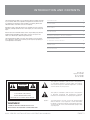
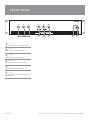
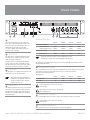
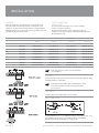
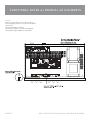
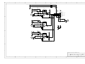
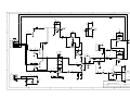
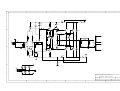
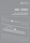
SERVICE INFORMATION
AMC30
MIXER AMPLIFIER
CONTENTS:
OPERATION MANUAL
SCHEMATIC DIAGRAMS
Australian Monitor
1 Clyde Street, Silverwater NSW 2128 Australia
+61 2 9647 1411
www.australianmonitor.com.au
AMC SERIES
3 0 W / 6 0 W /1 2 0 W /2 5 0 W M I XE R AM P L I F I ERS
INS TA LLAT I ON AN D OP E RAT I ON M AN UAL
I M P O RTA N T SAF E TY INF ORMATION
1.
Save the carton and packing material even if the equipment has
arrived in good condition. Should you ever need to ship the unit, use
only the original factory packing.
2.
Read all documentation before operating your equipment. Retain
all documentation for future reference.
3.
Follow all instructions printed on unit chassis for proper operation.
4.
Do not spill water or other liquids into or on the unit, or operate
the unit while standing in liquid.
5.
Make sure power outlets conform to the power requirements listed
on the back of the unit.
6.
Do not use the unit if the electrical power cord is frayed or broken.
The power supply cords should be routed so that they are not likely
to be walked on or pinched by items placed upon or against them,
paying particular attention to cords and plugs, convenience
receptacles, and the point where they exit from the appliance.
7.
8.
Always operate the unit with the AC ground wire connected to the
electrical system ground. Precautions should be taken so that the
means of grounding of a piece of equipment is not defeated.
13. Do not block fan intake or exhaust ports. Do not operate equipment
on a surface or in an environment which may impede the normal flow
of air around the unit, such as a bed, rug, weathersheet, carpet,
or completely enclosed rack. If the unit is used in an extremely dusty
or smoky environment, the unit should be periodically “blown free”
of foreign matter.
14. Do not remove the cover. Removing the cover will expose you
to potentially dangerous voltages. There are no user serviceable
parts inside.
15. Do not drive the inputs with a signal level greater than that required
to drive equipment to full output.
16. Do not connect the inputs / outputs of amplifiers or consoles to any
other voltage source, such as a battery, mains source, or power supply,
regardless of whether the amplifier or console is turned on or off.
17. Do not run the output of any amplifier channel back into another
channel’s input. Do not parallel- or series-connect an amplifier output
with any other amplifier output. Australian Monitor Inc is not
responsible for damage to loudspeakers for any reason.
18. Do not ground any red (“hot”) terminal. Never connect a “hot” (red)
output to ground or to another “hot” (red) output!
Mains voltage must be correct and the same as that printed on the
rear of the unit. Damage caused by connection to improper AC voltage
is not covered by any warranty.
19. Non-use periods. The power cord of equipment should be unplugged
from the outlet when left unused for a long period of time.
9.
Have gain controls on amplifiers turned down during power-up
to prevent speaker damage if there are high signal levels at the inputs.
20. Service Information Equipment should be serviced by qualified service
personnel when:
10
Power down & disconnect units from mains voltage before making
connections.
A.
The power supply cord or the plug has been damaged.
B.
Objects have fallen, or liquid has been spilled into the equipment
11. Never hold a power switch in the “ON” position if it won’t stay
there itself!
C. The equipment has been exposed to rain
12. Do not use the unit near stoves, heat registers, radiators, or other heat
producing devices.
D. The equipment does not appear to operate normally, or exhibits a marked
change in performance
E. The equipment has been dropped, or the enclosure damaged.
INTRODUCTION AND CONTENTS
The Australian Monitor AMC series of amplifiers takes the heritage & reliability of our famous AMIS series amplifiers & integrates these features into low
cost amplifiers for applications where reliability is everything, but the more
elaborate features of our AMIS series are not required.
I NT RODUCT I ON
3
F RONT PANE L
4
Available in 30, 60, 120 & 250 watt versions, the AMC series are 2 RU mixer
amplifiers, featuring 70/100 volt line & 4 ohm outputs, & 3 universal mic/line
inputs
RE AR PANE L
5
I NSTAL L AT I ON
6
T ROUBL E SHOOT I NG & BL OCK DI AGRAM
7
F UNCT I ONAL NOT E S
& I NT E RNAL ADJ UST ME NT S
8
DI ME NSI ONS
9
Master volume & overall treble & bass controls are provided, along with Vox
triggered muting (defeatable), giving channel 1 priority over inputs 2 & 3.
There is also the facility to add a tone generator card.
The Australian Monitor AMC series gives the contractor a low cost alternative in applications that are price sensitive, but still require a high quality of
sound reproduction & reliability.
SP E CI F I CAT I ONS
10
AUS, EUR, USA
Copyright 1st Apr 2005
Rev A: 1st Apr 2005
Rev B: 6th Jun 2006
This symbol is intended to alert the user to the presence
of uninsulated “dangerous voltage” within the products
enclosure that may be of sufficient magnitude to constitute
a risk of electric shock to persons.
CAUTION
RISK OF ELECTRIC SHOCK
DO NOT OPEN
CAUTION: TO REDUCE THE RISK OF ELECTRIC SHOCK,
This symbol is intended to alert the user to the presence
of important operational and maintenance (servicing)
instructions in the literature accompanying the appliance.
DO NOT REMOVE COVER (OR BACK),
NO USER SERVICEABLE PARTS INSIDE,
REFER SERVICING TO QUALIFIED SERVICE PERSONAL.
Caution:
WARNING!
TO REDUCE THE RISK OF FIRE OR ELECTRIC HOCK
To prevent electric shock do not use this (polarised) plug
with an extension cord, receptacle or other outlet unless
the blades can be fully inserted to prevent blade exposure.
To prevent electric shock, match wide blade of plug to wide
slot, fully insert.
DO NOT EXPOSE THIS EQUIPMENT TO RAIN OR MOISTURE.
A M C S E R I E S I N S TA L L AT I O N & O P E R AT I O N M A N U A L
PA G E 3
F R O N T PA N E L
1
1
2
3
4
5
6
CH 1-3
These control the levels for each channel input.
2
BASS
There is 12dB of cut and boost at 100Hz.
3
TREBLE
There is 9dB of cut and boost at 10kHz.
4
MASTER
This controls the overall mixed output level.
5
ON
This LED indicates the unit is powered “on”.
6
POWER
This switch switches power on or off the mains. The
up position is on.
PA G E 4
A M C S E R I E S I N S TA L L AT I O N & O P E R AT I O N M A N U A L
R E A R PA N E L
6
1
5
4
CH 1-3
Each channel input section has two inputs: XLR
input - This is a balanced microphone input. It has
an input sensitivity of 1mV. RCA input - This is an
unbalanced line level input. It has an input
sensitivity of 500mV. The two RCA sockets are
summed to mono internally.
2
LINE OUTPUT
The LINE output is on a balanced XLR connector. The
output level is 1V into 1k at rated output.
NOTE: When wiring the LINE output as
unbalanced, Pin2 should be wired as hot
and Pin1 should be wired as ground/
shield. Do not wire Pin3.
4
3
1
AMC30
AMC60
AMC120
AMC250
166ohm
333ohm
83ohm
166ohm
41ohm
83ohm
20ohm
40ohm
4ohm
4ohm
4ohm
4ohm
Distributed Line Output
70V (115V version)
100V (230/240V version)
Low Impedance Output
(both versions)
NOTE: Only connect one output - either Distributed Line or Low
Impedance per channel. Do LowZ and 70/100V at the same time
The output strip comes fitted with a touch-proof cover held in place by two M3 machine screws
with flat and spring washers..
5
IEC MAINS INPUT SOCKET
This is a standard IEC 3 pin socket. It accepts a standard IEC mains cable, provided. The fuse draw
at 5 contains the mains fuse and a spare. The mains fuse is a time lag (slow blow)
HRC 20mm x 5mm ceramic type fuse.
The ratings are:
AMC30
AMC60
AMC120
AMC250
230V/240V model
115V model
0.5A
1.6A
2A
3.15A
1A
3.15A
4A
6.3A
Always replace the fuse with one of the same
value and type.
DIRECT OUT
The speaker connections are on the 12 pole terminal
strip. There is a low impedance output (OHM) and
a distributed line voltage output (LINE). 70V out is
available on 115V models. 100V out is available on
230V/240V models.
2
MINIMUM IMPEDANCE
TAPE OUTPUT
The TAPE output is on unbalanced RCA connectors.
The output level is 150mV into 10kohm at rated
output. The output is dual mono.
The TAPE output is not affected by the MASTER
volume control or the BASS and TREBLE controls.
The TAPE output does not receive the tone signal if
the optional tone generator module is installed.
3
7
NOTE: Always disconnect power to the amplifier
before replacing fuses.
6
VOLTAGE SELECT SWITCH
(only on 230V/240V models) This switch is used to select the mains voltage for your region.
Always replace the fuse with one of the same
value and type.
7
(OPTIONAL) TONE MODULE
These terminals are for use with an optional tone module (not supplied).
A M C S E R I E S I N S TA L L AT I O N & O P E R AT I O N M A N U A L
PA G E 5
I N S TA L L AT I O N
MOUNTING
When rack mounting, it is advisable to allow 1 rack space above and
below the amplifier. When multiple amplifiers are mounted in a rack,
exhaust fans should be used on the rack. Airflow for cooling the AMC30,
AMC60 & AMC120 is by convection from bottom to top. Airflow for cooling
the AMC250 is by fan from front to back.
OUTPUT
100V
70V
4 ohm
DISTANCE
OUTPUT CONNECTIONS
DIRECT OUTPUT
The output terminal strip accepts wire sizes from 16-22AWG
(1.5mm2 – 0.35mm2) or spade lugs.
The following table should be used as a guideline for cable sizes.
Regulations in your area may require different gauged wire and should
be checked before using.
WIRE SIZE
AMC30
AMC60
AMC120
AMC250
Up to 50m
AWG26(0.12mm2)
AWG26(0.12mm2)
AWG24(0.2mm2)
AWG22(0.35mm2)
50m–200m
AWG24(0.2mm2)
AWG20(0.5mm2)
AWG18(0.75mm2)
AWG16(1.5mm2)
Over 200m
AWG20(0.5mm2)
AWG18(0.75mm2)
AWG16(1.5mm2)
AWG13(2.5mm2)
Up to 50m
AWG26(0.12mm2)
AWG24(0.2mm2)
AWG22(0.35mm2)
AWG18(0.75mm2)
50m–200m
AWG20(0.5mm2)
AWG18(0.75mm2)
AWG16(1.5mm2)
AWG13(2.5mm2)
Over 200m
AWG18(0.75mm2)
AWG16(1.5mm2)
AWG13(2.5mm2)
AWG10(6.0mm2)
Up to 10m
AWG18(0.75mm2)
AWG18(0.75mm2)
AWG18(0.75mm2)
AWG18(0.75mm2)
10m–30m
AWG13(2.5mm2)
AWG13(2.5mm2)
AWG13(2.5mm2)
AWG13(0.35mm2)
Over 30m
Not Recommended
Not Recommended
Not Recommended
Not Recommended
NOTE: Only connect one output - either Distributed Line
or Low Impedance.
LINE OUTPUT
he LINE output XLR can be used to connect up to 6 booster amplifiers. Balanced wiring
(shielded pair cable) is recommended.
NOTE: When wiring the LINE output as unbalanced, Pin2 should
be wired as hot and Pin1 should be wired as ground/shield.
Do not wire Pin3.
TAPE OUTPUT
The TAPE output wiring should be kept as short as possible.
INPUT CONNECTIONS
For wiring balanced in, pin 2 is hot. Unbalanced wiring on the microphone inputs is not
recommended. Balanced input wiring (shielded pair cable) is recommended.
Unbalanced RCA wiring should be keep as short as possible.
PA G E 6
A M C S E R I E S I N S TA L L AT I O N & O P E R AT I O N M A N U A L
TROUBLESHOOTING & BLOCK DIAGRAM
TRO UBL E S HOOT IN G GU I D E
TROUBLE
LIKELY CAUSE
REMEDY
Power LED not on
Power not reaching amplifier
Check mains connection
Check mains fuse
Check power switch is on
Distorted sound
Output is short circuit
Input is overloaded
Output is being over driven
Bass control is turned up
Check speaker loads for shorts
Reduce input level at source
Reduce volume levels on front panel
Reduce Bass control level
No sound but amp is on
Volume controls down
Amplifier has overheated
(AMC60, AMC120 AMC250 only)
Check volume controls
Check for obstructions above and below
Make sure the amplifier is
well ventilated.
DC fuse(s) blown
Refer product to local Australian Monitor dealer
No sound from channels 2 & 3
Priority function is being used
Remove signal (disconnect input) from
channel 1 OR Disable priority function
(see Internal Adjustments)
Condenser microphone does not work
Amplifier does not have phantom power
Purchase an external power supply OR
Upgrade to the AMIS range of amplifiers
Tones do not sound when triggered
Tone generator module not installed.
Purchase optional Tone generator module
A M C S E R I E S I N S TA L L AT I O N & O P E R AT I O N M A N U A L
PA G E 7
FUNCTIONAL NOTES & INTERNAL ADJUSTMENTS
PRIORITY
Channel 1 will mute channels 2 and 3. This will only occur
when signal appears on channel 1, irrespective of the channel
volume control.
Priority can be disabled. (See below).
The release time is approx. 3 secs and is NOT adjustable.
The mute depth is approx. 40dB and is not adjustable.
PA G E 8
A M C S E R I E S I N S TA L L AT I O N & O P E R AT I O N M A N U A L
DIMENSIONS
A M C S E R I E S I N S TA L L AT I O N & O P E R AT I O N M A N U A L
PA G E 9
S P E C I F I C AT I O N S
AMC 30
AMC 60
AMC 120
AMC 250
30W
60W
120W
250W
> 75dBr
> 75dBr
> 80dBr
>85dBr
85Hz-15kHz
75Hz-15kHz
75Hz-15kHz
30Hz-20kHz
MAINS (115V)
1.0A
3.15A
4A
6.3A
MAINS (230/240V)
0.5A
1.6A
2A
3.15A
1.6A (x2)
4A
8A
10A (x2)
96%
93%
93%
90%
482x88x190mm
19”x3.5”x7.5”
482x88x281mm
19”x3.5”x11.1”
482x88x281mm
19”x3.5”x11.1”
482x88x384mm
19”x3.5”15.1”
NET WEIGHT
6.0kg
13.2lb
8.5kg
18.7lb
10.5kg
23.1lb
11.5kg
25.3lb
SHIPPING WEIGHT
7.5kg
16.5lb
10.5kg
23.1lb
12.5kg
27.6lb
14kg
30.8lb
510x145x297mm
20.1”x5.7”x11.7”
525x175x385mm
20.7”x6.9”x15.2”
525x175x385mm
20.7”x6.9”x15.2”
525x185x470mm
20.7”x7.3”x18.5”
0.35A
0.66A
1.20A
2.53A
1/3 POWER
0.23A
0.44A
0.80A
1.61A
1/8 POWER
0.17A
0.32A
0.55A
1.10A
IDLE
0.08A
0.13A
0.15A
0.15A
0.73A
1.38A
2.50A
5.28A
1/3 POWER
0.48A
0.92A
1.67A
3.36A
1/8 POWER
0.35A
0.67A
1.15A
2.30A
IDLE
0.17A
0.27A
0.31A
0.31A
POWER OUTPUT (0.5%THD, 1KHZ)
S/N RATIO
POWER BANDWIDTH (-3DB +1DB)
FUSES
DC
OUTPUT REGULATION
SIZE (WXHXD)
SHIPPING DIMENSIONS (WXHXD)
MAINS CURRENT DRAW (240V)
FULL POWER
MAINS CURRENT DRAW (115V)
FULL POWER
PA G E 1 0
A M C S E R I E S I N S TA L L AT I O N & O P E R AT I O N M A N U A L
S P E C I F I C AT I O N S
AMC 30
AMC 60
AMC 120
AMC 250
38W
67W
128W
259W
1/3 POWER
33W
63W
118W
231W
1/8 POWER
26W
51W
91W
168W
IDLE
11W
19W
26W
26W
130
229
437
884
1/3 POWER
113
215
403
788
1/8 POWER
90
172
311
573
IDLE
38
65
89
89
THERMAL OUTPUT (W)
FULL POWER
THERMAL OUTPUT (BTU/HR)
FULL POWER
*1/3 and 1/8 power levels relate to voltage changes, not load changes.
COMMON TO ALL MODELS
THD (1KHZ, -1DB)
MIC INPUT
AUX INPUT
better than 0.5%
SENSITIVITY
1mV @ 200ohm
IMPEDANCE
1k3 ohm
HEADROOM
77mV (37dB)
SENSITIVITY
0.5V+/@100kohm
IMPEDANCE
>200kohm
HEADROOM
> 15V (>30dB)
TONE CONTROL BASS @ 100HZ
+/- 12 dB
TREBLE @ 10KHZ
+/- 9 dB
LINE OUT
NOMINAL OUTPUT
OUTPUT IMPEDANCE
TAPE OUT
NOMINAL OUTPUT
OUTPUT
IMPEDANCE
A M C S E R I E S I N S TA L L AT I O N & O P E R AT I O N M A N U A L
1V @ 1kohm
100ohm
300mV @ 10kohm
10kohm
PA G E 1 1
AUSTRALIA AND NEW ZEALAND
w w w. a u s t r a l i a n m o n i t o r. c o m . a u
SYDNEY
MELBOURNE
BRISBANE
ADELAIDE
PERTH
AUCKLAND
(NSW & ACT SALES)
(VIC & TAS SALES)
(QLD SALES)
(SA & NT SALES)
(WA SALES)
(NZ SALES)
149 Beaconsfield
Street Silverwater
NSW 2128
Private Bag 149
Silverwater NSW 1811
Phone: (02) 9647 1411
Fax: (02) 9648 3698
Email:
[email protected]
22/277
Middleborough Road
Box Hill VIC 3128
PO Box 151 Blackburn
South VIC 3130
Phone: (03) 9890 7477
Fax: (03) 9890 7977
Email:
[email protected]
42 Commercial Road
Fortitude Valley
QLD 4006
PO Box 871 Fortitude
Valley QLD 4006
Phone: (07) 3852 1312
Fax: (07) 3252 1237
Email:
[email protected]
31 Walsh Street
Thebarton
SA 5031
PO Box 157
Hindmarsh SA 5007
Phone: (08) 8352 4444
Fax: (08) 8352 4488
Email:
[email protected]
299 Fitzgerald Street
West Perth WA 6005
PO Box 404
North Perth
WA 6906
Phone: (08) 9228 4222
Fax: (08) 9228 4233
Email:
[email protected]
Unit B, 11 Piermark
Drive Albany 1331
New Zealand
PO Box 512
Albany 1331
Phone: (09) 415 9426
Fax: (09) 415 9864
Email:
[email protected]
EUROPE / ASIA / MIDDLE EAST
USA / SOUTH AMERICA
w w w. a u s t r a l i a n m o n i t o r. c o m . a u
w w w. a u s t r a l i a n m o n i t o r. c o m
INTERNATIONAL SALES
SENNHEISER ELECTRONIC CORPORATION
149 Beaconsfield Street Silverwater NSW 2128 Australian
Private Bag 149 Silverwater NSW 1811
Phone: (02) 9647 1411
Fax: (02) 9648 3698
Email: [email protected]
1 Enterprise Drive
Old Lyme CT 06371 USA
Phone: 1 860 434 9190
Fax: 1 860 434 1759
Email: [email protected]
XLR-FEMALE
1
2
1
3
4
5
6
7
8
R20
1K
TAPE OUT
R21
1K
R2
330K
C25
4u7
R6
22K
D
R3
330K
C8
10/25 NP
R4
680R
C9
10/25 NP
D
R19
10R
C2
100P
R1
680R
C7
10/25 NP
C1
GRD
AG(1/2 VCC)
+VCC
CH 1 OUT
CH 2 OUT
CH 3 OUT
MIX OUT
MIX OUTD
TAPE OUT
C10
4u7
8
6
7
5
IC1B
LM833
C11
.1u
R5
22K
100P
R7
330K
C21
4u7
R9
22K
R8
330K
C
R11
680R
C13
10/25 NP
C14
10/25 NP
C22
4u7
C3
C
C12
4u7
2
R12
680R
C15
10/25 NP
LINE OUT
100P
1
3
IC1A
LM833
4
C4
100P
R10
22K
R14
330K
R18
22K
R15
330K
C18
10/25 NP
R16
680R
C17
10/25 NP
R13
680R
C16
10/25 NP
R20
10R
C6
100P
C19
4u7
8
6
B
7
IC2B
LM833
C5
100P
B
5
R17
22K
C20
.1u
A
A
Australian Monitor
C
AMC30 Mic Input
1
2
3
4
5
6
7
8
1
2
3
4
6
5
100R
R46
R47
100R
R7
39k
VCC
C3
22pF
C1
4u7
2
R23
10K
IC1A
1458
1
T5
C1815
TAPE OUT
C8
VR1
47k
1/2VCC
C7
4u7
R10
10k
C19
47/25V
33n
1/2VCC
R24
10K
4
3
R1
4k7
D
C13
100P
R41
2K2
R18
10k
R12
10k
VR4
50k
R17
10k
R34
10k
GND 1/2VCCVCC
C9
1200P
4.7u
R11
6k8
J2
0
R2
2k2
R6
2k2
X2
R13
6k8
VR5
50k
VR2
47k
T1
LK1
6
1
2
3
C1815
IC1B
1458
1/2VCC
VR3
47k
C15
47pf
R20
1M
A
VCC
1K5
VCC
1N4148
IC4B
1458
R36
10K
R21
100E
10k
R39
100k
10/25
C11
4u7
R33
VR6
50k
4u7
R15
4k7
C16
R22
100K
IC3A
1458
1
3
B
T2
NC
R40
10k
R4
100k
1/2VCC
C20
470/25
VCC
R26
NC
R28
NC
IC4A
1458
D3
NC
R29
47/25
2
4k7
2
1
TH+
3
NC
TH1
1K
t
R25
NC
D5
LED1
AMC30 Mixer
1
2
3
4
5
TO AMP
TH-
Australian Monitor
D4
12V/1W
TO AMP
NC
R27
NC
R37
220E/2W
C21
1000/25
C12
22PF
C2
R5
3.9v
D1
7
5
CN2
R32
D2
VCC
6
Signal
1/2VCC
4
R19
4K7
4.7U
R31
BC556
2K2
C14
IN+
INTHTH+
R30
T3
C1815
1
2
3
4
5
6
T4
8
2k2
VCC
R38
10k
BAV21
R8
OUT-
C17
VCC
D6
R3
2k2
C
IN-
R16
22K
7
5
B
VCC
Tone Module Input
VCC
IN+
IC3B
1458
1
2
3
4
5
6
7
C10
47PF
OUT+
7
5
C4
+12V
CH1
CH2
CH3
Line OUT+
Line OUT-
Signal
4
1
2
3
4
5
6
7
8
8
CN1
C
VCC
6
8
D
6
A
1
2
3
4
6
5
+M
D
D6
D2
1N4148
R3
150E
C3
47uF/25
T1
A1145
R13
100E
R12
R14
2K2
C1
1
2
3
220n
R1
T2
A1145
3K3
R2
10K
470E
R15
100E
T7
BD139
R16
1K2
330E
PR1
2K
15PF
C6
47/25
T5
C1815
4E
1mm/13T
C
R30
R26
68E
R28
0.22E/5W
T10
A1015
D1
100/35 1N4007
R29
10E/1W
R31
10E/1W
COM
PRIM
100V
47E
C10
0.1uF/100V
D5
1N4007
T12
A1358
470E
T14
TIP36
C11
0.1uF/100V
D9
COM
1N4007
T8
C2705
C4
L1
R24
R17
82E
C16
220PF/50V
R7
68E
R27
0.22E/5W
C9
47/25
R20
R6
68E
R25
68E
10E/1W
R32 R9
330E
T4
C1815
D8
1N4007
47E
R22
47E+150E
R23
390E
C5
C2
330PF
T13
TIP35
R21
R8
10K
T3
A1145
T11
C3421
D4
1N4007
T9
C1815
+M
CN1
R19
T6
A1145
R11
6K8
R5
100E
1N4007
C7
D3
1N4148
R10
6K8
R4
100E
D
1.6A
100/35
2K2
C
F?
R18
0E
-M
B
D7
1N4007
B
F?
1.6A
C8
100/35
+M
D10
CN2
1
2
3
CON2
1N5402
D12
1N5402
D11
1N5402
D13
1N5402
C14
2200uF/35V
C15
2200uF/35V
-M
A
A
Australian Monitor
AMC30 Amplifier
1
2
3
4
5
6