1
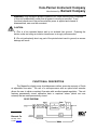
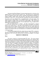
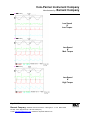
Cole-Parmer Instrument Company
Manufactured by: Barnant Company
SERVICE MANUAL
MODELS:
75211-30 Console, 115 Vac, 60 to 3600 r/min
75211-35 Console, 230 Vac, 60 to 3600 r/min
75211-40 NEMA Modular, 115 Vac, 60 to 3600 r/min
75211-41 Controller only
75211-42 Motor only
75211-45 NEMA Modular, 230 Vac, 60 to 3600 r/min
75211-46 Controller only
75211-47 Motor only
PROPRIEARY
Information contained in this manual is proprietary to the BARNANT COMPANY,
division of COLE-PARMER INSTRUMENT COMPANY, INC. No reproduction for other
than the intended use of maintaining the product described herein is permitted without
the permission of BARNANT.
TABLE OF CONTENTS
Page 1 of 24
Barnant Company y 28W092 Commercial Avenue y Barrington, IL
847-381-7050 y 800-637-3739 y 847-381-7053 (Fax)
e-mail: [email protected] y Web Site: http//www.barnant.com
U.S.A. 60010-2392
Cole-Parmer Instrument Company
Manufactured by: Barnant Company
INTRODUCTION............................................................................................................. 3
SAFETY CONSIDERATIONS ......................................................................................... 4
FUNCTIONAL DESCRIPTION........................................................................................ 5
THEORY OF OPERATION ............................................................................................. 6
TROUBLESHOOTING .................................................................................................. 15
REPAIR PROCEDURES............................................................................................... 18
REPLACEMENT PARTS LISTING................................................................................ 21
CALIBRATION ............................................................................................................. 22
FUNCTIONAL TESTS................................................................................................... 23
ASSOCIATED DOCUMENTS ....................................................................................... 25
INTRODUCTION
Service for this product is performed at three levels: the customer,
distributor/COLE-PARMER and factory/depot repair. This manual describes distributor/COLE-PARMER service procedures.
Page 2 of 24
Barnant Company y 28W092 Commercial Avenue y Barrington, IL
847-381-7050 y 800-637-3739 y 847-381-7053 (Fax)
e-mail: [email protected] y Web Site: http//www.barnant.com
U.S.A. 60010-2392
Cole-Parmer Instrument Company
Manufactured by: Barnant Company
Customer service procedures are described in the operator's manual.
Customers are encouraged to perform service as described in the operator's manual as
well as in special circumstances where special skills and safety are not considerations.
To use this manual, begin with the troubleshooting section to isolate the fault to a
replaceable part. The functional description and check-out procedure sections are also
helpful in determining the faulty part. Distributor/COLE-PARMER repair is limited to
replacement of modules as detailed in the replacement parts list section. The repair
procedures section details disassembly and assembly procedures. After repair, the
product should be calibrated and checked for proper performance.
Please refer to the operator's manual for:
A) Applications Data
B) Product Description
C) Installation
D) Setup
E) Operation
F) User Calibration
G) User Troubleshooting & Maintenance
H) Accessories
I) Specifications
SAFETY CONSIDERATIONS
Servicing must be performed only by personnel trained and skilled in the
methods of troubleshooting and repair of electromechanical products.
Use of
procedures other than those described in this manual may result in a safety hazard to
service personnel and/or customers.
Page 3 of 24
Barnant Company y 28W092 Commercial Avenue y Barrington, IL
847-381-7050 y 800-637-3739 y 847-381-7053 (Fax)
e-mail: [email protected] y Web Site: http//www.barnant.com
U.S.A. 60010-2392
Cole-Parmer Instrument Company
Manufactured by: Barnant Company
WARNING: High voltage is present inside the unit, when servicing any component
of this unit be absolutely certain that all power to circuitry is removed. If any
functional checks are to be performed while power is applied and chassis is
disassembled, care must be exercised.
CAUTION:
A.) This is a line operated device and is not isolated from ground. Powering the
device under test using an isolation transformer is strongly recommended.
B.) Do not inadvertently short any part of the printed circuit card to ground, as severe
damage will result.
FUNCTIONAL DESCRIPTION
The Masterflex digital pump drive/dispensers deliver accurate amounts of fluids
at adjustable flow rates. The use of a microprocessor with an optical shaft encoder
allows the user to obtain consistent flow rates with excellent speed regulation. The unit
features permanently stored calibration data or empirical values (which are user
entered) that are semi-permanently stored.
Page 4 of 24
Barnant Company y 28W092 Commercial Avenue y Barrington, IL
847-381-7050 y 800-637-3739 y 847-381-7053 (Fax)
e-mail: [email protected] y Web Site: http//www.barnant.com
U.S.A. 60010-2392
Cole-Parmer Instrument Company
Manufactured by: Barnant Company
As shown on the Block Diagram, the motor (pump) speed (w) is a function of the
applied torque (T) acting on the rotor inertia (1/sJ). The torque in turn is proportional
(Kt) to the armature current (Iarm), which is produced by the difference between the
applied armature voltage (Varm) and the motor back EMF across the armature
impedance (1/(Ra+s*La)). The motor back EMF, generated in the armature windings by
the motion of the rotor magnetic field, is proportional (Kw) to the motor speed. The
applied armature voltage (Varm) is the amplified (Kwreg) error signal between the
speed reference command (wref) and the motor speed (wfdbk). The motor speed
signal (Kfdbk) is supplied by the drive to the microprocessor using an optical sensor
tachometer mounted on the motor.
The unit contains two P. C. Boards. The Main Control Board is mounted
vertically on the left side of the unit in the console drives and parallel to the chassis
base in the modular drives. The Main Control Board has four main areas: the
microprocessor and its related circuitry, the remote I/O, the motor power bridge and
control, and the power supply. The Display Board, containing two dual 7-segment LED
displays and mounted on the front of the enclosure, is connected via a flat ribbon cable
to the control board.
The membrane keypad, which also contains the annunciator LED's, is secured to
the front of the enclosure with pressure-sensitive adhesive. There are three flat flex
tails (switch, LED’s, and static shield ground) connecting the keypad to the Display
Board.
THEORY OF OPERATION
Motor
The pump is driven by a brush-commutated DC motor. The motor converts
electrical energy into mechanical energy through the interaction of two magnetic fields.
One field is produced by a permanent magnet assembly attached to the motor shell; the
other field is produced by an electric current flowing through the armature windings.
These two fields produce a torque that causes the armature to rotate. As the armature
turns, the current is switched (commutated) among the windings to produce a
continuous torque output. The back emf is an induced voltage produced by the relative
motion between the permanent magnet field and the armature windings. This allows
simple speed and torque control as the speed is proportional to the applied voltage,
while the torque is proportional to the current through the motor. On the peristaltic
pump drives, the speed of the motor is reduced through a system of gears to provide
the speed required by the pump.
Page 5 of 24
Barnant Company y 28W092 Commercial Avenue y Barrington, IL
847-381-7050 y 800-637-3739 y 847-381-7053 (Fax)
e-mail: [email protected] y Web Site: http//www.barnant.com
U.S.A. 60010-2392
Cole-Parmer Instrument Company
Manufactured by: Barnant Company
Phase-Controlled Rectifier Speed Control
The variable speed drive employs a phase-controlled rectifier bridge to vary the
power applied to the DC motor. The bridge will only conduct current when the power
line voltage exceeds the voltage across the motor terminals. The power to the motor
can therefore be controlled by varying the point at which the bridge starts to conduct,
relative to the phase of the line voltage. The phase angle at which the bridge starts
conducting is controlled by a speed regulator loop. Synchronization to the power line is
provided by a differential line cross comparator circuit U12A. Current and voltage
waveforms for both the line and motor are shown for various load and speed variations.
D32, D33, Q9, and Q10 form the main power bridge for the motor. D32 and Q10
conduct during one-half of the line cycle, while D33 and Q9 conduct during the other
half. Reversals of the line voltage force the conducting SCR to commutate off. Since
switching is at zero voltage during line cross, there is no flyback pulse from the motor to
clamp. Opto-triacs U14 and U15 isolate the power line from the control circuits. RV1
and RV2 provide transient voltage protection from power line surges caused by other
power conversion equipment and lightning strikes. RV1 and RV2 are in parallel with the
transformer T1 primaries, which are selected between 115 Vac and 230 Vac operation
with a line voltage selector switch SW1. Common mode choke L3 and line-to-ground
capacitors C52 and C54 filter out conducted common-mode noise, while across-the-line
capacitors C50 and C51 filter out conducted differential noise.
A dynamic brake resistor attached to the contacts of the ON/OFF relay (K2)
brings the motor to a stop before reversing to avoid damage to the motor or drive.
Page 6 of 24
Barnant Company y 28W092 Commercial Avenue y Barrington, IL
847-381-7050 y 800-637-3739 y 847-381-7053 (Fax)
e-mail: [email protected] y Web Site: http//www.barnant.com
U.S.A. 60010-2392
Cole-Parmer Instrument Company
Manufactured by: Barnant Company
Low Speed
&
Low Torque
Low Speed
&
Med. Torque
Low Speed
&
High Torque
Page 7 of 24
Barnant Company y 28W092 Commercial Avenue y Barrington, IL
847-381-7050 y 800-637-3739 y 847-381-7053 (Fax)
e-mail: [email protected] y Web Site: http//www.barnant.com
U.S.A. 60010-2392
Cole-Parmer Instrument Company
Manufactured by: Barnant Company
Med. Speed
&
Low Torque
Med. Speed
&
Med. Torque
Med. Speed
&
High Torque
Page 8 of 24
Barnant Company y 28W092 Commercial Avenue y Barrington, IL
847-381-7050 y 800-637-3739 y 847-381-7053 (Fax)
e-mail: [email protected] y Web Site: http//www.barnant.com
U.S.A. 60010-2392
Cole-Parmer Instrument Company
Manufactured by: Barnant Company
High Speed
&
Low Torque
High Speed
&
Med. Torque
High Speed
&
High Torque
Speed Feedback & Regulator
Speed feedback is provided by a slotted encoder wheel and optical sensor. The
IR output of the sensor diode is interrupted by slots in an encoder wheel attached to the
motor shaft. The IR sensor output is filtered by C37, C67, and C66. The offset is
removed by C68 and level shifted by R125 and R127. U12C compares the sensor
output against the reference level formed by R94 and R126. R109 provides hysteresis
Page 9 of 24
Barnant Company y 28W092 Commercial Avenue y Barrington, IL
847-381-7050 y 800-637-3739 y 847-381-7053 (Fax)
e-mail: [email protected] y Web Site: http//www.barnant.com
U.S.A. 60010-2392
Cole-Parmer Instrument Company
Manufactured by: Barnant Company
for noise filtering. Additional filtering is provided by C65 and C36.
provides a buffered tachometer signal to the user.
Transistor Q4
The encoder pulses from the comparator output are counted by the
microprocessor to determine the motor speed. Schmitt trigger U2E speeds up the slew
rate of the comparator U12C output. The difference between the set speed and the
motor speed is used by the microprocessor to determine the required phase angle to
fire the output SCR’s.
The interrupt service routine for the line cross interrupt reads the number of
encoder pulses stored in the pulse accumulator register (PACNT), resets the PWM
output, updates the copy/dispense counter, and sets the SCR firing angle. The speed
error (speed_err) is the difference between the speed setpoint (control_ppi) and the
actual speed (actual_ppi), derived from the number of pulses stored in the pulse
accumulator register between line crosses. The speed error (speed_err) is integrated
(intg_err := speed_err / 64 – intg_err * 1023). The integrator output (intg_err) and the
speed error (speed_err) are then used to calculate a new SCR firing angle (fire_cnt :=
speed_err/2 + intg_err * 1024 + BUZZ_CNT). BUZZ_CNT is a constant minimum count
( = 1365) needed to get the motor turning. Once calculated, the SCR firing angle
(fire_cnt) is subtracted from the average count of the processor clock per line cross
(avg_clks). This sum is then added to the existing counter value (TIC2) to generate the
value of the counter at the time the counter output fires the SCR (new_cnts).
CPU Section
The CPU, U8, for the system is a Motorola MC68HC11D0. The CPU is operated
from a crystal, Y1, at 9.8304 MHz. The RAM, ROM, data latch, and expanded I/O for
the system are provided by a WSI PSD312, mounted in a socket, X1. Non-volatile
memory for calibration and setup information is provided by the EEPROM, U6, which
has a serial interface to the CPU. The 5V digital supply level is monitored by U7 to
control the power-up/down reset of the CPU and the RAM/ROM/latch in the WSI
PSD312 IC. The CPU contains an independent, on-chip watchdog timer.
Display/Keypad
The digital drives use a 4 character, 7 segment light emitting diode (LED) display
for speed and flowrate information. Individual LED annunciators on the keypad show
setup information. Display segments and LED annunciators are matrix addressed by a
display driver chip, U1, which has a serial interface to the CPU. Current through the
LED’s is set by R9, while resistors R1 through R8 limit power dissipation through the
driver chip. Ferrite beads on the output lines filter out EMI. Matrix addressed keypad
Page 10 of 24
Barnant Company y 28W092 Commercial Avenue y Barrington, IL
847-381-7050 y 800-637-3739 y 847-381-7053 (Fax)
e-mail: [email protected] y Web Site: http//www.barnant.com
U.S.A. 60010-2392
Cole-Parmer Instrument Company
Manufactured by: Barnant Company
switch closures are read into an 8-bit parallel port on the WSI PSD312 chip.
network R47 through R62 and C17 through C24 provide EMI filtering.
RC
A/D Converter
The A/D converter, U5, is a 11 channel, 10-bit successive approximation
converter with a serial interface to the CPU. The +5V supply voltage is filtered by R34
and C12 and used as a reference voltage for the A/D. The A/D is self-clocking with an
end-of-conversion (EOC) signal to trigger a CPU interrupt. The address of the next
channel to be converted is clocked in as the previous conversion result is being clocked
out. Normally unused A/D channels are used to monitor the remote contact closure
input status.
Analog I/O (0-10V & 4-20mA)
Speed can be controlled through either an external 0-10V or an external 4-20mA
signal. The current signal is converted into a voltage for the A/D converter U5 by R15.
Differential buffer amplifiers U4C (Current) and U4D (Voltage) eliminate errors caused
by common mode voltages. Clamp diodes D1 and D3 protect U4C; D2 and D5 protect
U4D, while D9 and D10 and resistor dividers R26 through R33 protect A/D U5 from
over-voltages.
A PWM signal, proportional to motor speed, from pin 25 of the microprocessor
U8 is low-pass filtered by a three pole Bessel filter, with a 10 Hz bandwidth, formed by
U4B. The output is used for both an external 0-10V signal and a reference input for a
voltage to current converter formed by U9A and U4A. Emitter-follower Q2 permits the
output voltage to reach 0V.
The output voltage is converted into a current by voltage follower U9A, high-gain
transistor buffer Q6, and resistor R97. The open-loop gain of U4A forces the voltage
drops across R112 and the parallel combination of R113 and R98 to be equal. The
currents through the resistor network are therefore proportional to the relative resistor
values. Because of the high input impedance of U4A and the high gain of the Q3 and
Q5 transistor combination, the external 4-20mA signal is the current through the parallel
R113 and R98 resistor network.
Contact Closure Input (AUX IN, Remote Start/Stop, & Prime)
Resistors R11 to R13 and R72 are pull-ups for the contact closure inputs. Capacitors
C4 to C7 provide low pass filtering for the signals. Diodes D12, D14, D16, and D18 and
resistors R86 to R93, R149 to R151, and R46 protect against over-voltage transients.
Page 11 of 24
Barnant Company y 28W092 Commercial Avenue y Barrington, IL
847-381-7050 y 800-637-3739 y 847-381-7053 (Fax)
e-mail: [email protected] y Web Site: http//www.barnant.com
U.S.A. 60010-2392
Cole-Parmer Instrument Company
Manufactured by: Barnant Company
Power Supply
The primary power supply for the system is a 115 VAC or 230 VAC +/- 15%, 50
or 60 Hz, wall outlet. The rear panel power input module for the detachable power cord
contains the fuse. Switch SW1 on the Main PCB selects between 115 and 230 Vac
operation, so that the same PCB can be used for both voltages.
An unregulated +24 Vdc supplies power to the analog inputs and outputs, to the
relays K1 through K4, and to the +5 Vdc switching regulator U13, which supplies power
to the rest of the control circuits. The unregulated +24 Vdc is generated by filtering
(C49) a full-wave rectified (D22-D25), center-tapped secondary winding output of T1. A
double isolated transformer T1 is required to avoid ground loops and for safety, as the
remote inputs and outputs might provide an electrical connection to an energized
surface.
+5 V Switching Regulator
Shown below is a schematic representation of the U13, LM2594, +5Vdc
switching regulator circuit. In the figure, C1 corresponds to C49, L1 to E24, C2 to C53
and C62, D1 to D27 L2 to L4, and C2 to C55 and C56. The remaining components are
internal to U13. Circuit waveforms are shown in the figure following.
Page 12 of 24
Barnant Company y 28W092 Commercial Avenue y Barrington, IL
847-381-7050 y 800-637-3739 y 847-381-7053 (Fax)
e-mail: [email protected] y Web Site: http//www.barnant.com
U.S.A. 60010-2392
Cole-Parmer Instrument Company
Manufactured by: Barnant Company
Waveform B is the voltage at point A in the schematic. It is at +Vin for the time
Q1 is closed (Ton) and at ground for the time Q1 is open (T- Ton). The filter L2C2
averages out the Vin peak-to-peak ripple voltage to produce a constant dc output
voltage Vo whose value is given by:
Vo = Vin (Ton/T)
The LM 2594 regulator continually adjusts Ton to give a fixed +5Vdc output. The
period T remains fixed at a switching frequency of 150 KHz. The ripple voltage on Vo is
determined by the choice of L2 and C2. Waveforms C through F show currents through
the switch Q1, diode D1, inductor L2, and capacitor C2. The average value of current
through the inductor L2 must always equal the dc load current. The current through L2
ramps upward through Q1 when Q1 is closed and ramps downward through D1 when
Q1 is open. The inductor current ramp must not be allowed to go to zero, placing a
minimum limit on the allowable load current. When Q1 is closed, there is a constant
voltage across L2 equal to Vin - Vo. Since the voltage across and inductor is given by V
= L di/dt, the magnitude of the peak of the current ramp is given by:
∆IL = (Vin - Vo) Ton/L2 .
Page 13 of 24
Barnant Company y 28W092 Commercial Avenue y Barrington, IL
847-381-7050 y 800-637-3739 y 847-381-7053 (Fax)
e-mail: [email protected] y Web Site: http//www.barnant.com
U.S.A. 60010-2392
Cole-Parmer Instrument Company
Manufactured by: Barnant Company
TROUBLESHOOTING
Repairs on this unit are confined to either the unit’s Main PCB assembly and/or
drive motor assembly.
Page 14 of 24
Barnant Company y 28W092 Commercial Avenue y Barrington, IL
847-381-7050 y 800-637-3739 y 847-381-7053 (Fax)
e-mail: [email protected] y Web Site: http//www.barnant.com
U.S.A. 60010-2392
Cole-Parmer Instrument Company
Manufactured by: Barnant Company
Where possible, swap known good parts to localize and isolate the problem. The
following is a list of possible problems and remedies:
VERIFY AC POWER IS OPERATIVE.
MOTOR WILL NOT RUN, DISPLAY DOES NOT LIGHT:
1.
2.
3.
4.
5.
fuse blown
power cord not connected properly
AC power switch failure
unit connected to dead outlet
power supply failure
- replace fuse
- check & replace
- replace switch assembly
- verify supply is HOT
- replace main PCB assembly
UNIT BLOWS FUSES:
1. motor drive failure
2. defective main PCB
3. wrong fuse installed
- check using known good motor
- replace main PCB assembly
- check fuse rating
MOTOR WILL NOT REVERSE:
1. defective main PCB
2. defective keypad
- replace main PCB assembly
- replace keypad
MOTOR WILL NOT RUN, DISPLAY LIGHTS:
1.
2.
3.
4.
5.
defective keypad
defective main PCB
defective motor assembly
dirty encoder switch
wrong operating MODE
- replace keypad
- replace main PCB assembly
- replace motor assembly
- clean switch & disk
- MODE set to INT for front panel
operation, mA or V for remote operation
LOSS OF SPEED CONTROL, OR IMPROPER SPEEDS:
1. defective main PCB
2. dirty encoder switch
- replace main PCB assembly
- clean switch & disk
Page 15 of 24
Barnant Company y 28W092 Commercial Avenue y Barrington, IL
847-381-7050 y 800-637-3739 y 847-381-7053 (Fax)
e-mail: [email protected] y Web Site: http//www.barnant.com
U.S.A. 60010-2392
Cole-Parmer Instrument Company
Manufactured by: Barnant Company
NO REMOTE OPERATION:
1. defective main PCB
2. external cable not connected
properly
- replace main PCB assembly
- check/replace
DISPLAYED ERROR CODES
ERR = Bad calibration run
ERR1 = No encoder pulses, Motor undershoot
ERR2 = Motor overspeed, Motor overshoot
ERR3 = Not Used
ERR4 = Bad PROM checksum, program halted
ERR5 = Motor overload
ERR6 = Bad zero crossing detector or crystal
ERR7 = Bad EEPROM data, using operator parameter default values
ERR8 = Bad EEPROM data, using A/D calibration default values
ERR9 = EEPROM write/verify error
LOSS OF SPEED CONTROL, ERROR #1 DISPLAYED:
1. motor undershoot (no tubing in pump)
2. defective main PCB (encoder circuit)
3. defective motor/encoder assembly
- press any key to clear error
- replace main PCB assembly
- replace motor assembly
MOTOR IMMEDIATELY RUNS WHEN POWER IS APPLIED, ERROR #2 DISPLAYED:
1. motor overshoot (no tubing in pump)
2. defective main PCB (power bridge)
- press any key to clear error
- replace main PCB assembly
ERROR #4 DISPLAYED:
1. bad PROM
- replace PROM
MOTOR OVERLOAD, ERROR #5 DISPLAYED:
1. pump jammed
- clear obstruction, turn drive off then on
Page 16 of 24
Barnant Company y 28W092 Commercial Avenue y Barrington, IL
847-381-7050 y 800-637-3739 y 847-381-7053 (Fax)
e-mail: [email protected] y Web Site: http//www.barnant.com
U.S.A. 60010-2392
Cole-Parmer Instrument Company
Manufactured by: Barnant Company
ERROR #6 THROUGH #9 DISPLAYED:
1. turn unit off then on and/or press
any key to reset, if any error numbers
reappear
- replace main PCB assy.
NO DISPLAY OR GARBLED DISPLAY:
1. display connector not seated
2. display failure
3. defective main PCB (U1)
- reseat ribbon cable (J3)
- replace display PCB assembly
- replace main PCB assembly
IMPROPER KEYPAD OPERATION:
1. keypad failure
2. defective main PCB (PROM)
- replace keypad assy.
- replace PROM / main PCB assembly
FOR ADDITIONAL INFORMATION REGARDING YOUR UNIT PLEASE REFER
TO THE OPERATOR'S MANUAL.
REPAIR PROCEDURES
TO DISASSEMBLE UNIT, PROCEED AS FOLLOWS:
A) Disconnect AC power.
B) Remove the three (console drives) pan head screws on each side of the unit's cover.
On NEMA drives, loosen the four captive screws in the cover.
C) Lift off cover assembly.
TO REASSEMBLE UNIT, PROCEED AS FOLLOWS:
Page 17 of 24
Barnant Company y 28W092 Commercial Avenue y Barrington, IL
847-381-7050 y 800-637-3739 y 847-381-7053 (Fax)
e-mail: [email protected] y Web Site: http//www.barnant.com
U.S.A. 60010-2392
Cole-Parmer Instrument Company
Manufactured by: Barnant Company
A) Slide on cover assembly.
B) Install the three (console drives) pan head screws on each side of the unit's cover.
On NEMA drives, tighten the four captive screws in the cover.
TO REPLACE MOTOR ASSEMBLY (Console Drives Only):
A) Remove BLACK motor lead from J5.
B) Remove RED motor lead from J6.
C) Remove Motor Encoder Cable from J9.
D) Remove top nut holding GREEN ground wire to the chassis.
E) Remove four bolts holding motor to chassis.
F) Replace motor and tighten bolts. Attach leads and encoder cable.
TO REMOVE MAIN CONTROL PCB ASSEMBLY:
A) Console Drives: Remove two screws holding heat sink assembly to chassis.
Remove screw from PCB Card Guide. Remove PCB Card Guide.
NEMA Modular Drives: Remove two nuts holding heat sink bracket to chassis.
Remove two screws holding PCB to chassis. Remove two screws
holding heat sink assembly to heat sink bracket.
B) Remove all cables and wires from PCB.
TO REPLACE PROM:
NOTE: The part is in a 44-pin PLCC socket, but requires an extraction tool to avoid
damage to the socket and firmware chip. Recommended extraction tools are the OK
Industries EX-5 and the AMP #821981-1.
NOTE: To avoid ESD damage to the firmware chip, leave the chip in its protective
carrier until it is to be inserted. Wear an earth-grounded, anti-static wrist strap while
working on the drive.
A) The socket, holding the firmware, is located in the upper right-hand corner of the
Main PCB and is labeled X1 on the PCB silkscreen. Please note that the beveled
corner of the firmware chip will be in the lower right-hand corner of the socket. (See
Illustration.)
B) Place the extraction tool so that it is firmly seated in the socket and over opposite
corners of the firmware chip. Squeeze the handle to extract the chip.
Page 18 of 24
Barnant Company y 28W092 Commercial Avenue y Barrington, IL
847-381-7050 y 800-637-3739 y 847-381-7053 (Fax)
e-mail: [email protected] y Web Site: http//www.barnant.com
U.S.A. 60010-2392
Cole-Parmer Instrument Company
Manufactured by: Barnant Company
C) Making sure that the new firmware chip orientation is the same as that of the old,
place the replacement firmware chip in the socket. Keeping the chip level, gently
squeeze the chip into the socket until it is fully seated.
D) Drive setup information is in a separate EEPROM so that the drive will not need
recalibration. An Err 7 message will initially appear that can be cleared by pressing
STOP/START.
Bevel
TO REPLACE MAIN CONTROL PCB ASSEMBLY:
A) Note that the correct firmware is installed. Follow the steps outlined in "TO
REPLACE PROM".
B) Note that SW1 on the Main Control PCB is set for the correct line voltage (115 V /
230 V).
C) Note wiring of Main Control PCB as follows:
1) BLUE of power line to: J2
2) BROWN of power line to: J4
3) BLACK of drive motor to: J5
4) RED of drive motor to: J6
5) GREEN/YELLOW from Chassis Ground to J18 (Not on some 115 Vac drives)
6)
7)
8)
9)
Ribbon cable from Display PCB to J3
Cable from Motor Encoder to J9
Rear Panel DB-15 ribbon cable to J11
Two BROWN of Dynamic Brake Resistor to J16 & J17
Page 19 of 24
Barnant Company y 28W092 Commercial Avenue y Barrington, IL
847-381-7050 y 800-637-3739 y 847-381-7053 (Fax)
e-mail: [email protected] y Web Site: http//www.barnant.com
U.S.A. 60010-2392
Cole-Parmer Instrument Company
Manufactured by: Barnant Company
10) BLACK from AUX OUT 2 to J7
11) WHITE from AUX OUT 2 to J8
12) RED from AUX IN 1 to J1
13) GREEN from AUX IN 1 to J10
14) BROWN from AUX OUT 1 to J14
15) BLUE from AUX OUT 1 to J15
TO REMOVE DISPLAY PCB:
A)Remove 4 screws (console drives, 3 on NEMA modular drives) holding the PCB to
cover.
B)Remove ribbon cables. The ZIF sockets release the keypad flex tails by sliding out.
TO REPLACE DISPLAY PCB:
A) Replace cables. The ZIF sockets secure the keypad flex tails by sliding in.
1)
2)
3)
4)
Ribbon Cable (26 conductor) from Main Control PCB J3.
LED (11 conductor) flex tail from Keypad J2.
Switch (7 conductor) flex tail from Keypad J3.
Shield ground flex tail from Keypad – Secured and grounded to Display PCB with
screw.
B) Secure Display PCB with 4 screws (console drives, 3 on NEMA modular drives).
TO REPLACE KEYPAD:
A)
B)
C)
D)
Follow the steps outlined in "REMOVE DISPLAY PCB".
Peel keypad from cover.
Affix new keypad to cover.
Follow the steps outlined in "REPLACE DISPLAY PCB".
REPLACEMENT PARTS LISTING
The following is a list of stocked main control PCB assemblies, firmware,
keypads, and motor/drive assemblies for all indicated models:
MODEL #
PCB ASSY
PROM (X1)
KEYPAD
Page 20 of 24
Barnant Company y 28W092 Commercial Avenue y Barrington, IL
847-381-7050 y 800-637-3739 y 847-381-7053 (Fax)
e-mail: [email protected] y Web Site: http//www.barnant.com
U.S.A. 60010-2392
MOTOR ASSY
Cole-Parmer Instrument Company
Manufactured by: Barnant Company
75211-30
75211-35
75211-40
75211-45
E-2231-0002
E-2231-0002
E-2231-0002
E-2231-0002
5750
5750
5753
5753
5679
5679
5695
5695
D-3078-0001
D-3078-0002
75211-42
75211-47
The following list is commonly used parts applicable to the above model LISTINGS:
DESCRIPTION
BARNANT part #
Detachable power cord 115 Vac (USA)
B-3115
(C/P# 50001-68)
Detachable power cord 230 Vac (EUROPEAN)
B-2938
(C/P# 50001-70)
Display PCB Assy (Console Drive)
D-2974
Display PCB Assy (Modular Drives)
D-3224
Magnetic Coupler
A-3207
Brushes (Set of 2)
C/P# 7520-04
Brush Cap Holder
C/P# 7520-03
AC Switch w/Boot Console
5742
Page 21 of 24
Barnant Company y 28W092 Commercial Avenue y Barrington, IL
847-381-7050 y 800-637-3739 y 847-381-7053 (Fax)
e-mail: [email protected] y Web Site: http//www.barnant.com
U.S.A. 60010-2392
Cole-Parmer Instrument Company
Manufactured by: Barnant Company
CALIBRATION
Due to the design of this product, there are no calibrations and/or adjustments to be
performed other than set-ups performed by the customer. Calibration of the Analog I/O
requires a special calibration fixture at the factory.
Additional technical specifications are available in the unit's OPERATORS MANUAL.
FUNCTIONAL TESTS
1.00
Test equipment required:
1.01
1.02
1.03
2.00
Contact Tachometer (C-P Cat. # 8203-50 or 8203-80)
Variac 115 VAC, 60Hz or 230 VAC, 50Hz appropriate for unit being
tested.
Foot switch (C-P Cat. # 7595-42) or Remote Control (C-P Cat. # 7592-83)
TESTING:
2.01
2.02
2.03
2.04
Plug controller into the variac set to 115 volts ac or 230 volts appropriate
for the unit under test.
Turn the controllers power switch to the ON position. Verify that all LED’s,
display segments, and decimal points illuminate.
Verifying each LED illuminates for INT, mA, and V, press the MODE
switch to get to the INT mode.
Select any tubing size (not RPM), then press the FLOW key. The
Page 22 of 24
Barnant Company y 28W092 Commercial Avenue y Barrington, IL
847-381-7050 y 800-637-3739 y 847-381-7053 (Fax)
e-mail: [email protected] y Web Site: http//www.barnant.com
U.S.A. 60010-2392
Cole-Parmer Instrument Company
Manufactured by: Barnant Company
2.05
2.06
2.07
2.08
2.09
2.10
displayed value should change.
Press the CAL key. Note that the annunciator LED next to the key is
flashing. Press the Gear Set key to exit out of CAL.
Verifying the LED for each tubing illuminates, press the tubing SIZE
switch to get the RPM display.
Verifying each LED illuminates for mL, COPY, and SEC, press the
DISPense/copy key until none of the LED's is on.
Turn the drive OFF. While holding the MODE switch, turn the drive ON.
Set the input to 4-20mA (115 Vac) or 0-20mA (230 Vac) with the
increment (^) or decrement (v) keys. Press the MODE switch. Set the
output to 4-20mA (115 Vac) or 0-20mA (230 Vac), with the increment (^)
or decrement (v) keys. Press the MODE switch to get to the INT mode.
Turn the drive OFF then ON after a wait of at least three seconds. Verify
the INT and RPM indicators remain lit.
Press START and then press ^ until display reads the maximum setting.
Using the hand tach, verify motor runs within the specified tolerance.
NOTE: Motor should be rotating CW when viewed from the front.
Press v until display reads the minimum setting. Using the hand tach,
verify motor runs within the specified tolerance.
Drive
75211-30, -35,
-40, -45
2.11
2.12
2.13
2.14
Maximum Speed
Setting Max.
Min.
3600 3618
3582
Minimum Speed
Setting Max.
Min.
60
69
51
Press and hold the PRIME key while noting that the drive runs at full
speed.
Press the Remote Start/Stop (NEMA drives only) or foot switch. Verify
that the drive runs as long as it is held. Press STOP/START.
Press the Remote Prime switch (NEMA drives only). Verify that the drive
runs at full speed as long as it is held.
Turn the controller OFF and unplug it from the variac.
**************************
TESTS COMPLETED
***********************
Page 23 of 24
Barnant Company y 28W092 Commercial Avenue y Barrington, IL
847-381-7050 y 800-637-3739 y 847-381-7053 (Fax)
e-mail: [email protected] y Web Site: http//www.barnant.com
U.S.A. 60010-2392
Cole-Parmer Instrument Company
Manufactured by: Barnant Company
ASSOCIATED DOCUMENTS
Current copies of the following documents are required for servicing the drive:
Main PCB Schematic:
Main PCB Assy Dwg:
Console Drive Display PCB Schematic:
Modular Drive Display PCB Schematic:
Operator’s Manual:
75211-30/35:
75210-40/45:
E-2229
E-2231
D-2972
D-3035
A-1299-0853
A-1299-0854
The following documents may be of help and are included for reference:
Chassis Assy Dwg:
75211-30/35:
75210-40/45:
5745
5739
Cover Assy Dwg:
75211-30/35:
75210-40/45:
5744
5740
Page 24 of 24
Barnant Company y 28W092 Commercial Avenue y Barrington, IL
847-381-7050 y 800-637-3739 y 847-381-7053 (Fax)
e-mail: [email protected] y Web Site: http//www.barnant.com
U.S.A. 60010-2392