1
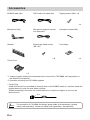
R
PXI-H990
Multimedia ManagerTM
Guide for Installation and Connections
English
Guide d’installation et de connexions
Français
Guía de instalación y conexiones
Español
Español
Italiano
Svenska
R
ALPINE ELECTRONICS MARKETING, INC.
1-1-8 Nishi Gotanda,
Shinagawa-ku, Tokyo 141-0031, Japan
Phone 03-5496-8231
ALPINE ELECTRONICS OF AMERICA, INC.
19145 Gramercy Place, Torrance,
California 90501, U.S.A.
Phone 1-800-ALPINE-1 (1-800-257-4631)
ALPINE ELECTRONICS OF CANADA, INC.
7300 Warden Ave., Suite 203, Markham,
Ontario L3R 9Z6, Canada
Phone 1-800-ALPINE-1 (1-800-257-4631)
ALPINE ELECTRONICS OF AUSTRALIA PTY. LTD.
6-8 Fiveways Boulevarde Keysborough,
Victoria 3173, Australia
Phone 03-9769-0000
ALPINE ELECTRONICS GmbH
Frankfurter Ring 117, 80807 München,
Germany
Phone 089-32 42 640
ALPINE ELECTRONICS OF U.K. LTD.
Alpine House
Fletchamstead Highway,
Coventry CV4 9TW, U.K.
Phone 0870-33 33 763
ALPINE ELECTRONICS FRANCE S.A.R.L.
(RCS PONTOISE B 338 101 280)
98, Rue de la Belle Etoile, Z.I. Paris
Nord II, B.P. 50016, 95945 Roissy
Charles de Gaulle Cedex, France
Phone 01-48638989
ALPINE ITALIA S.p.A.
Viale C. Colombo 8, 20090 Trezzano
Sul Naviglio (MI), Italy
Phone 02-484781
ALPINE ELECTRONICS DE ESPAÑA, S.A.
Portal de Gamarra 36, Pabellón, 32
01013 Vitoria (Alava) - APDO 133, Spain
Phone 945-283588
Sankei Kikaku Co., Ltd.
1-13-38, Hinodai,
Hino, Tokyo, Japan
Designed by ALPINE Japan
Printed in Japan (S)
68-00323Z20-A
PRECAUTIONS
GUIDE FOR INSTALLATION AND CONNECTIONS
• Please read this GUIDE FOR INSTALLATION AND CONNECTIONS and the OWNER’S
MANUAL thoroughly to familiarize yourself with each control and function. We at ALPINE hope
that your new PXI-H990 will give you many years of listening enjoyment.
In case of problems when installing your unit, please contact your authorized ALPINE dealer.
Points to Observe for Safe Usage
• Read this manual carefully before starting operation and use this system safely. We cannot be
responsible for problems resulting from failure to observe the instructions in this manual.
• This manual uses various pictorial displays to show how to use this product safely and to avoid
harm to yourself and others and damage to your property.
Here is what these pictorial displays mean. Understanding them is important for reading this
manual.
• Meaning of displays
Warning
This symbol means important instructions. Failure to heed them can
result in serious injury or death.
Caution
This symbol means important instructions. Failure to heed them can
result in injury or property damage.
Warning
DO NOT DISASSEMBLE OR ALTER. Doing so may result in an accident, fire or electric shock.
USE THE CORRECT AMPERE RATING WHEN REPLACING FUSES. Failure to do so may
result in fire or electric shock.
MAKE THE CORRECT CONNECTIONS. Failure to make the proper connections may result in
fire or product damage.
USE ONLY IN CARS WITH A 12 VOLT NEGATIVE GROUND. (Check with your dealer if you are
not sure.) Failure to do so may result in fire, etc.
BEFORE WIRING, DISCONNECT THE CABLE FROM THE NEGATIVE BATTERY TERMINAL.
Failure to do so may result in electric shock or injury due to electrical shorts.
DO NOT ALLOW CABLES TO BECOME ENTANGLED IN SURROUNDING OBJECTS. Arrange
wiring and cables in compliance with the manual to prevent obstructions when driving. Cables or
wiring that obstruct or hang up on places such as the steering wheel, gear lever, brake pedals,
etc. can be extremely hazardous.
DO NOT SPLICE INTO ELECTRICAL CABLES. Never cut away cable insulation to supply power
to other equipment. Doing so will exceed the current carrying capacity of the wire and result in fire
or electric shock.
2-EN
DO NOT DAMAGE PIPE OR WIRING WHEN DRILLING HOLES. When drilling holes in the
chassis for installation, take precautions so as not to contact, damage or obstruct pipes, fuel
lines, tanks or electrical wiring. Failure to take such precautions may result in fire.
DO NOT USE BOLTS OR NUTS IN THE BRAKE OR STEERING SYSTEMS TO MAKE
GROUND CONNECTIONS. Bolts or nuts used for the brake or steering systems (or any other
safety-related system), or tanks should NEVER be used for installations or ground connections.
Using such parts could disable control of the vehicle and cause fire etc.
DO NOT BLOCK VENTS OR RADIATOR PANELS. Doing so may cause heat to build up inside
and may result in fire.
KEEP SMALL OBJECTS SUCH AS BATTERIES OUT OF THE REACH OF CHILDREN. Swallowing them may result in serious injury. If swallowed, consult a physician immediately.
DO NOT INSTALL IN LOCATIONS WHICH MIGHT HINDER VEHICLE OPERATION, SUCH AS
THE STEERING WHEEL OR GEARSHIFT. Doing so may obstruct forward vision or hamper
movement etc. and results in serious accident.
Caution
HAVE THE WIRING AND INSTALLATION DONE BY EXPERTS. The wiring and installation of
this unit requires special technical skill and experience. To ensure safety, always contact the
dealer where you purchased this product to have the work done.
USE SPECIFIED ACCESSORY PARTS AND INSTALL THEM SECURELY. Be sure to use only
the specified accessory parts. Use of other than designated parts may damage this unit internally
or may not securely install the unit in place. This may cause parts to become loose resulting in
hazards or product failure.
ARRANGE THE WIRING SO IT IS NOT CRIMPED OR PINCHED BY A SHARP METAL EDGE.
Route the cables and wiring away from moving parts (like the seat rails) or sharp or pointed
edges. This will prevent crimping and damage to the wiring. If wiring passes through a hole in
metal, use a rubber grommet to prevent the wire’s insulation from being cut by the metal edge of
the hole.
DO NOT INSTALL IN LOCATIONS WITH HIGH MOISTURE OR DUST. Avoid installing the unit
in locations with high incidence of moisture or dust. Moisture or dust that penetrates into this unit
may result in product failure.
3-EN
Precautions
• Be sure to disconnect the cable from the (–) battery post before installing your PXI-H990. This
will reduce any chance of damage to the unit in case of a short-circuit.
• Be sure to connect the color coded leads according to the diagram. Incorrect connections may
cause the unit to malfunction or damage to the vehicle’s electrical system.
• When making connections to the vehicle’s electrical system, be aware of the factory installed
components (e.g. on-board computer). Do not tap into these leads to provide power for this
unit. When connecting the PXI-H990 to the fuse box, make sure the fuse for the intended
circuit of the PXI-H990 has the appropriate amperage. Failure to do so may result in damage to
the unit and/or the vehicle. When in doubt, consult your ALPINE dealer.
• The PXI-H990 uses female RCA-type jacks for connection to other units (e.g. amplifier) having
RCA connectors. You may need an adaptor to connect other units. If so, please contact your
authorized ALPINE dealer for assistance.
• Be careful not to cause a short by jamming the cable into the computer when connecting. It
can cause a fault.
• Alpine accepts no responsibility for damaged or lost data in your computer etc., even if data
etc., is damaged or lost while using this product.
Wiring Connections
Improper wiring connections could cause serious damage to your audio system. Be sure you:
1. DO NOT connect (–) wires from left and right speakers together.
2. DO NOT ground any speaker wires.
3. DO NOT run wires where they may be pinched or cut.
4. DO NOT leave bare speaker terminals exposed. They may contact the vehicle chassis and
cause a short.
Fuse
When replacing the fuse(s), the replacement fuse must be of the same amperage as shown on
the fuse holder. If the fuse(s) blows more than once, carefully check all electrical connections for
shorted circuitry. Also have your vehicle’s voltage regulator checked. Do not attempt to repair the
unit yourself; return it to your Alpine dealer or nearest Alpine Service Station for servicing.
Temperature
In order to ensure proper performance, be sure the temperature in your vehicle is above 14°F
(–10°C) and below 140°F (60°C) before turning your unit on. Good air circulation is essential to
prevent internal heat build-up in the unit.
4-EN
Contents
PRECAUTIONS
2
Accessories
6
Installation
7
Connections
10
Examples of system expansion
12
IMPORTANT
Please record the serial number of your unit in the space provided below and keep it as a permanent record. The serial number plate is located on the bottom of the unit.
SERIAL NUMBER:
INSTALLATION DATE:
INSTALLATION TECHNICIAN:
PLACE OF PURCHASE:
To prevent external noise from entering the audio system.
• Locate the unit and route the leads at least 10 cm away from the car harness.
• Keep the battery power leads as far away from other leads as possible.
• Connect the ground lead securely to a bare metal spot (remove any paint, dirt or grease if
necessary) of the car chassis.
• If you add an optional noise suppressor, connect it as far away from the unit as possible.
Your Alpine dealer carries various noise suppressors. Contact them for further information.
• Your Alpine dealer knows best about noise prevention measures so consult your dealer for
further information.
5-EN
Accessories
IONBUS cable (6m)
DVD Audio Link cable (6m)
Tapping screws (M4 x 14)
x4
Microphone (6m)
2
Bracket*
Microphone terminal connec1
tion cable (6m)*
Hexagonal wrench (M3)
Bracket pan head screws
2
(M4 x 8)*
Cord clamp
x8
x4
Ferrite Core
x2
*1 Used only when setting the microphone built in the monitor (TMI-M990, sold separately) as
the Road EQ microphone.
*2 Use when mounting two PXI-H990s together.
• Ferrite Core
Attach the Ferrite Core (included) to the both ends of the IONBUS cable at a location where the
product does not touch the core when installing.
(When connecting to the main unit, attach the core at a location of approx. 4 cm from the
terminal end.)
4cm
Memo
6-EN
For connection of PXI-H990, the battery power cable (sold separately), ground
cable (sold separately), remote out cable (sold separately), are necessary.
Installation
• Mounting the base unit
1. Decide on the installation location.
• The trunk, etc., is the best place.
2. Mark the positions of the mounting screws at the chosen location.
3. Drill 3 mm (1/8”) holes or smaller.
WARNING: When making holes, be careful not to damage pipes, tanks, electric wires, etc.
Doing so could lead to accidents or fire.
4. Securely mount the unit using the four included tapping screws (M4 x 14).
Tapping screws (M4 x 14)
7-EN
< Setting up two PXI-H990s >
Find a location that can accommodate both unit together then proceed with the following procedure.
To set up two PXI-H990s, first connect both base units before setting them up.
1. Remove the feet from the base unit sides that have no terminals. One screw holds each
foot in place.
Foot
2. Remove the screw from the top part of one base unit marked with ★ using the supplied
hexagonal wrench (M3). Reverse the direction of the plate and re-attach it as shown
below.
Before re-attaching the plate, change the INDICATOR switch to “REVERSE”. (For Basic Connections Diagram, refer to page 10)
★
★
8-EN
3. Place two base units side by side, and attach the brackets with the supplied bracket pan
head screws (M4 x 8).
Bracket pan head screw (M4 x 8)
4. Refer to “Mounting the base unit” on page 7, and firmly attach the base.
Memo
When using two PXI-H990s, change the System switch on the base unit to
“DUAL”. (For Basic Connections Diagram, refer to page 10)
• Mounting Microphone
Mounting Location
Mount the microphone on the rear-view mirror, headrest, sun visor, or other appropriate location.
• We recommend that you mount it on the sun visor.
1. Attaching the microphone
After mounting the microphone, use the supplied cord clamp to dress the microphone cable.
• You can use the internal microphone in the monitor (TMI-M990, sold separately) as a Road
EQ Microphone. For more details about connecting, refer to “Examples of system expansion”
(page 13).
• When connecting two PXI-H990s, connect the microphones to both units. In this case, the
mouting location of two microphones should be the same.
• When connecting two PXI-H990s, the Road EQ microphone built in the monitor (TMI-M990,
sold separately) cannot be used.
9-EN
Connections
• Basic Connections Diagram
< Top view >
Memo
Normally the various
indicators are lit blue.
Dolby digital indicator
Lights red during Dolby Digital decoding.
DTS indicator
Lights up red during DTS decoding.
LPCM indicator
Lights up red when LPCM (MLP Lossless or
CD-DA) input.
Road EQ Indicator
Lights up red when Road EQ is ON.
★
Memo
Remove the screw marked ★ using the included
hexagonal wrench (M3).
< Base section >
DUAL
REAR
FRONT
SINGLE
System switch
• Set to SINGLE when connecting one PXI-H990.
• When connecting two PXIH990s, set the first to FRONT,
and the second to REAR.
Memory on/off selector switch
Set this switch to LOCK to prevent your settings and adjustments stored in memory from being erased accidentally.
Indicator change switch
When using two PXI-H990s, switch to REVERSE for the second
processor to match the indicator of the first processor.
10-EN
< Side Panel >
Memo
Terminal specification
Connect to:
• DVD Audio Link terminal
Terminal for DVD audio playback.
Connect to the DVD Audio
terminal of the DVI-9990 head
unit, etc., using the DVD Audio
Link cable.
• Microphone terminal
Connect microphone.
Connect to the microphone terminal with the supplied microphone
terminal connection cable when using the separately sold monitor
(TMI-M990) internal Road EQ microphone.
Connect to the microphone
(supplied with the main unit) or
the separately sold monitor
(TMI-M990) Road EQ
microphone terminal.
• USB terminal
Used to make settings and adjustments with a
computer. USB cable (mini B type) and computer
software are required. For details, contact your
store of purchase or an Alpine Information Center.
Connect to a computer's USB
terminal with a USB cable (mini
B type).
• Ground terminal
Connect securely to a metal part of the vehicle’s
body using the ground cable.
Connect to the vehicle’s body
using the ground cable.
• Remote OUT terminal
Connect to the amplifier or other peripheral device.
Connect to amplifier.
• Battery power terminal
Power is supplied constantly to the PXI-H990
regardless of whether the engine key is on or off.
Connect to a cable to which
power is constantly supplied.
• IONBUS terminal
Use when connecting with an IONBUS
compatible terminal or upgrading the system.
Connect to the IONBUS
terminal using the IONBUS
cable.
• Audio input terminal (RCA input)
Accepts an audio signal output from videos etc.
Connect using an RCA cable.
Connect to any product with an
audio output terminal using
RCA-type connectors.
• Audio output terminal (RCA output)
Outputs an audio signal.
Connect to amplifier.
• Remove the DVD Audio link, IONBUS or USB terminal covers when connecting
the DVD Audio Link cable, the IONBUS cable or the USB cable.
Leave the covers on when not using the DVD Audio link, IONBUS or USB terminal.
* Depending upon the system configuration, the outputs will drive different types of speaker drivers.
When one PXI-H990 is connected
When two PXI-H990s are connected
SYSTEM2
SYSTEM4 (Front) SYSTEM4 (Rear)
SYSTEM1
CH-1
CH-2
CH-3
CH-4
Front L TW
Front R TW
Front L WF
*1
Front R WF
*1
SYSTEM3
Front L TW
Front L*1
Front L TW
Front R TW
*1
Front R TW
Front R
*2
Front L MID
*2
Front R MID
Front C
Sub WF 1
Rear L TW
Rear R TW
*2
Rear L WF
*2
Rear R WF
Front L MID
Front R MID
Rear L
Front L WF*2
Rear L
Front L WF
Rear R
Front R WF*2
Rear R
Front R WF*2
Rear C WF
CH-7
Front C
Sub WF 1
Rear C
Front C TW
Sub WF 1
CH-8
Sub WF
Sub WF 2
Sub WF 2
Front C WF
Sub WF 2
CH-5
CH-6
*2
Rear C TW
*1 There is no OFF setting.
*2 It is not possible to turn both “MID” and “WF” off.
If one is set to “OFF”, the other cannot be set to “OFF”.
Memo
• It is necessary to change the setting corresponding with the speaker (system).
(See “Setting the speakers” on the Owner’s Manual)
• Do not connect the tweeter (TW) to the channel without “TW” indicated in the table
above. If connected, the speaker may be damaged.
• For SYSTEM 1, REAR TW cannot be connected.
• For SYSTEM 3, FRONT TW and REAR TW cannot be connected.
11-EN
Examples of system expansion
• PXI-H990 + DVI-9990 Head Unit + External Amplifier + Video etc.
DVD Audio Link cable
(Included)
DVD Audio Link cable
(Included)
System switch
DUAL
To DVD Audio
Link terminal
To DVD Audio
Link terminal
To DVD Audio
Link terminal
To DVD Audio
Link terminal
REAR
FRONT
SINGLE
Set to REAR
IONBUS
compatible
head unit (sold
separately)
DUAL
REAR
FRONT
SINGLE
Set to FRONT
IONBUS cable
(Included)
RCA connection
cable (sold
separately)
To Audio
output
terminal
Video,
game, etc.
Audio output
terminal
*1
To external
amplifier (refer
to page 11)
IONBUS cable
(Included)
*1
Battery power cable
(sold separately)
Ground cable
(sold separately)
System switch
To external
amplifier (refer
to page 11)
To IONBUS terminal
To IONBUS terminal
*1
*1
To Audio input terminal
Audio output
terminal
To IONBUS terminal
DVI-9990
Remote OUT cable
(sold separately)
Ground cable
(sold separately)
Fix to metal part of the car
with a screw
Fix to metal part of the car
with a screw
Remote
OUT cable
(sold
separately)
Connect to external
amplifier remote on lead
Connect to external
amplifier remote on lead
Battery power cable
(sold separately)
12V
*1 Ferrite Core (See page 6)
NOTE
• When connecting the Battery power cable direct to the battery terminal, a fuse at the battery should be used to protect
your equipment. Please consult with your Alpine dealer for the proper fuse value.
12-EN
• PXI-H990 + DVI-9990 Head Unit + TMI-M990 Monitor + Ai-NET compatible
Changer Connected
To IONBUS
terminal
DVI-9990
IONBUS
compatible head
unit (sold
separately)
TMI-M990
*1
To Road EQ
microphone
terminal
IONBUS
compatible
monitor (sold
separately)
IONBUS cable
*1
To S video input
terminal
S video cable (Supplied
with the head unit)
To S video
output terminal
To DVD Audio Link terminal
To IONBUS
terminal
DVD Audio Link cable
(Included)
*1
System switch
Microphone terminal connection cable (Included)*2
1:SYSTEM
To microphone
terminal
To DVD Audio
Link terminal
2:STANDALONE
1
2
Set to SYSTEM
IONBUS cable
(Supplied with the monitor)
To IONBUS
terminal
System switch
*1
*1
IONBUS cable
(Supplied with
the converter)
To IONBUS
terminal
*1
To IONBUS
terminal
Ai-NET compatible
CD changer (sold
separately)
(CHA-S634 etc.)
DUAL
Ai-NET/IONBUS
converter (sold
separately)
To Ai-NET
connector
REAR
FRONT
SINGLE
Set to SINGLE
(When only one
PXI-H990 is
connected)
KCI-500B
Ai-NET cable (Supplied
with the changer)
*1 Ferrite Core (See page 6).
Two pieces are attached to PXI-H990,TMI-M990, KCI-500B.
*2 Only connected when using the TMI-M990 internal Road EQ microphone. Otherwise connect with the microphone
(Included).
•
•
•
IONBUS compatible products can be connected in any order. The connection order shown above is an example.
When an Ai-NET compatible changer is not connected, then the KCI-500B does not need to be connected.
For details about connections, refer to the instruction manual of the product you are connecting with.
13-EN