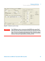
1
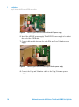
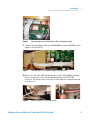
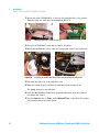
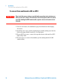
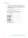
Agilent G1978B
Multimode Source for
6410 Triple Quad LC/MS
Set-Up Guide
Agilent Technologies
Notices
© Agilent Technologies, Inc. 2008
Warranty
No part of this manual may be reproduced in
any form or by any means (including electronic storage and retrieval or translation
into a foreign language) without prior agreement and written consent from Agilent
Technologies, Inc. as governed by United
States and international copyright laws.
The material contained in this document is provided “as is,” and is subject to being changed, without notice,
in future editions. Further, to the maximum extent permitted by applicable
law, Agilent disclaims all warranties,
either express or implied, with regard
to this manual and any information
contained herein, including but not
limited to the implied warranties of
merchantability and fitness for a particular purpose. Agilent shall not be
liable for errors or for incidental or
consequential damages in connection with the furnishing, use, or performance of this document or of any
information contained herein. Should
Agilent and the user have a separate
written agreement with warranty
terms covering the material in this
document that conflict with these
terms, the warranty terms in the separate agreement shall control.
Manual Part Number
G1978-90090
Edition
First Edition, December 2008
Printed in USA
Agilent Technologies, Inc.
5301 Stevens Creek Blvd.
Santa Clara, CA 95051 USA
Windows® and MS Windows® are U.S.
registered trademarks of Microsoft Corporation.
Windows NT® is a U.S. registered trademark of Microsoft Corporation.
Technology Licenses
The hardware and/or software described in
this document are furnished under a license
and may be used or copied only in accordance with the terms of such license.
Restricted Rights Legend
U.S. Government Restricted Rights. Software and technical data rights granted to
the federal government include only those
rights customarily provided to end user customers. Agilent provides this customary
commercial license in Software and technical data pursuant to FAR 12.211 (Technical
Data) and 12.212 (Computer Software) and,
for the Department of Defense, DFARS
252.227-7015 (Technical Data - Commercial
Items) and DFARS 227.7202-3 (Rights in
Commercial Computer Software or Computer Software Documentation).
2
Safety Notices
CAUTION
A CAUTION notice denotes a hazard. It calls attention to an operating procedure, practice, or the like
that, if not correctly performed or
adhered to, could result in damage
to the product or loss of important
data. Do not proceed beyond a
CAUTION notice until the indicated
conditions are fully understood and
met.
WA R N I N G
A WARNING notice denotes a
hazard. It calls attention to an
operating procedure, practice, or
the like that, if not correctly performed or adhered to, could result
in personal injury or death. Do not
proceed beyond a WARNING
notice until the indicated conditions are fully understood and
met.
Multimode Source for 6400 Series Triple Quad LC/MS Set-Up Guide
In This Guide
This guide explains how to install, maintain and troubleshoot your multimode
ion source.
1
Installation
This chapter tells you how to install the multimode source.
2
Performance Verification
This chapter describes how to set up methods and autotune the source.
Multimode Source for 6400 Series Triple Quad LC/MS Set-Up Guide
3
4
Multimode Source for 6400 Series Triple Quad LC/MS Set-Up Guide
Content
1
Installation
7
Installation 8
Step 1. Prepare to install 8
Step 2. Install the HV control PCA and cables
9
Changing Sources 13
To remove the multimode source 13
To convert from multimode to ESI or APCI 14
To convert from ESI or APCI to the multimode source
2
Performance Verification
15
21
To review methods and run worklist 22
To do sensitivity verification 24
To autotune with the multimode source 27
To set up a method to use the multimode source
Multimode Source for 6400 Series Triple Quad LC/MS Set-Up Guide
28
5
Contents
6
Multimode Source for 6400 Series Triple Quad LC/MS Set-Up Guide
Agilent G1978B Multimode Source for 6410 Triple Quad LC/MS
Set-Up Guide
1
Installation
Installation 8
Step 1. Prepare to install 8
Step 2. Install the HV control PCA and cables 9
Changing Sources 13
To remove the multimode source 13
To convert from multimode to ESI or APCI 14
To convert from ESI or APCI to the multimode source 15
This chapter contains instructions to install the multimode source on a 6400
Series Triple Quad LC/MS system, and also to remove and replace the source.
Agilent Technologies
7
1
Installation
Installation
Installation
Step 1. Prepare to install
The Multimode Enablement Kit, G1978-60451, is shipped with the multimode
source. This kit needs to be installed before the multimode source is used.
Note that the multimode source and its accessories are to be installed by an
Agilent Customer Engineer.
1 Check that the Multimode Enablement Kit contains the following parts:
• Multimode Bd HV Cable, p/n G1960-60858
• Multimode HV PCA, p/n G1960-61015
• Multimode Bd Power/Data Cable, p/n G1960-60873
Figure 1
From left to right: G1960-60858, G1960-61015 and G1960-60873
2 Install the APCI Enablement Kit, G1947-60451, which is shipped with the
multimode source.
The APCI Enablement kit contains the following parts:
• Fast APCI HV Supply, p/n G1946-80058
• Valve BD-APCI Supply Cable, p/nG1960-60802
• Valve BD-APCI Needle Interlock Cable, p/n G1960-60856
8
Multimode Source for 6400 Series Triple Quad LC/MS Set-Up Guide
Installation
Step 2. Install the HV control PCA and cables
Figure 2
1
From left to right: G1946-80058, G1960-60802 and G1960-60856
Step 2. Install the HV control PCA and cables
1 Turn off the system power and remove the system power cord.
The power cord should be kept intact if the vacuum control switch box is
used. The switch box is intended to keep the vacuum on while a service
engineer works on the electronics. The switch box is for service engineer
use only.
2 Remove the CDS cover, top, side, front, and the Aux Module cover.
3 Disconnect the ribbon cable that connects the valve PCA to the
Vcap/Vchamber power supply. Then disconnect the Vcap and Vchamber
cable from the power supply.
Figure 3
Disconnecting the Vcap/Vchamber power supply from the valve PCA (left) and the Vcap/Vchamber.
4 Place the MM HV power supply PCA in the slot between the valve PCA and
the Vcap/Vchamber power supply. Secure the board by pressing it down
into its slot and then attach it with two screws.
5 Connect the short gray cable from the valve PCA to the multimode HV
power supply.
Multimode Source for 6400 Series Triple Quad LC/MS Set-Up Guide
9
1
Installation
Step 2. Install the HV control PCA and cables
Figure 4
Connecting the valve PCA to the multimode HV power supply.
6 Install the APCI HV power supply. The APCI HV power supply is located at
the end of the AUX Module.
7 Connect ribbon cable between the valve PCA and Vcap/Vchamber power
supply.
Figure 5
Connecting the valve PCA to the Vcap/Vchamber power supply.
8 Connect the Vcap and Vchamber cables to the Vcap/Vchamber power
supply.
10
Multimode Source for 6400 Series Triple Quad LC/MS Set-Up Guide
Installation
Step 2. Install the HV control PCA and cables
Figure 6
1
Connecting the Vcap and Vchamber cables to the power supply.
9 Connect the long ribbon cable, p/n G1960-60802, from the APCI HV power
supply to the valve PCA.
Figure 7
Connecting the APCI HV power supply to the valve PCA.
10 Insert one end of the APCI Needle Interlock cable, G1960-60856, through
the slot at the front of the system and then plug it to the APCI HV
connector. Attach the other end to the chassis with the o-ring and the nut
(see Figure 8).
Figure 8
Connecting the APCI HV to the chassis.
Multimode Source for 6400 Series Triple Quad LC/MS Set-Up Guide
11
1
Installation
Step 2. Install the HV control PCA and cables
11 Insert the cable, G1960-60858, to the top slot and attach it to the chassis.
Plug the other two ends into the multimode HV PCA.
Figure 9
Connecting the HV PCA to the chassis.
12 Close the AUX Module cover and reconnect all cables.
13 Install the multimode source onto the system and connect all connectors.
Figure 10
Installing the multimode source (left) and connecting all connectors.
14 Put back the side, top, front and CDS cover.
15 Plug the system power cord back on and turn the front switch on.
The pump down process will start.
16 Start the MassHunter Workstation program and verify that the software
recognizes the source.
17 Set the Context view to Tune, and in Manual Tune, verify that the system
can generate the proper tune peaks.
12
Multimode Source for 6400 Series Triple Quad LC/MS Set-Up Guide
Installation
Changing Sources
1
Changing Sources
To remove the multimode source
Do the following steps to remove the multimode source.
1 Turn off the multimode source temperatures and flows:
a Change the Context view to Acquisition.
b Click the MS QQQ tab.
c Turn off all voltages and temperatures in the Source tab.
WA R N I N G
Do not touch the multimode source or the capillary cap. They may be very hot. Let
the parts cool before you handle them.
WA R N I N G
Never touch the source surfaces, especially when you analyze toxic substances or
when you use toxic solvents. The source has several sharp pieces which can pierce
your skin including the APCI corona needle, vaporizer sensor and counter current
electrode.
WA R N I N G
Do not insert fingers or tools through the openings on the multimode chamber. When
in use, the capillary and capillary cap are at high voltages up to 4 kV.
2 Wait approximately 20 minutes or until the source is cool.
3 Open the CDS door at the front of the MS to access the cables.
4 Disconnect the ESI high voltage charging electrode cable.
5 Disconnect the APCI Needle Interlock, and multimode HV cable.
6 Unscrew the nebulizer gas line from the nebulizer.
7 Unscrew the LC sample tubing from the nebulizer.
8 Open the latch on the source and open the source.
9 Remove the multimode source from the spray chamber mount.
10 Place the source shipping cover on the source.
Multimode Source for 6400 Series Triple Quad LC/MS Set-Up Guide
13
1
Installation
To convert from multimode to ESI or APCI
To convert from multimode to ESI or APCI
WA R N I N G
Never touch the source surfaces, especially when you analyze toxic substances or
when you use toxic solvents. The source has several sharp pieces which can pierce
your skin including the APCI corona needle, vaporizer sensor and counter current
electrode.
1 Unscrew and remove the multimode spray shield with the field shaping
electrodes.
2 Install the new source and the standard spray shield, making sure that the
hole in the spray shield is in the 12 o'clock position.
3 For an APCI ion source, connect the vaporizer heater cable and the APCI
high voltage cable.
4 For all sources, reconnect the nebulizer gas line tubing and the LC/MS
sample tubing.
14
Multimode Source for 6400 Series Triple Quad LC/MS Set-Up Guide
Installation
To convert from ESI or APCI to the multimode source
1
To convert from ESI or APCI to the multimode source
CAUTION
If you are installing this source on this instrument for the first time, follow the steps in
“Installation” on page 7.
1 Turn off the multimode source temperatures and flows:
a Change the Context view to Acquisition.
b Click the MS QQQ tab.
c Turn off all voltages and temperatures in the Source tab.
2 Wait for the source to cool (until temperatures are at least below 100°C).
3 Disconnect the nebulizer gas tubing from the currently installed ion source.
4 Disconnect the LC/MS sample inlet tubing.
5 If the APCI source is installed, remove the APCI vaporizer heater cable and
APCI high voltage cable.
6 Remove the currently installed ion source.
7 Unscrew and remove the spray shield. See Figure 11.
WA R N I N G
Do not touch the multimode source or the capillary cap. They may be very hot. Let the
parts cool before you handle them.
WA R N I N G
Do not insert fingers or tools through the openings on the multimode chamber. When
in use, the capillary and capillary cap are at high voltages up to 4 kV.
Multimode Source for 6400 Series Triple Quad LC/MS Set-Up Guide
15
1
Installation
To convert from ESI or APCI to the multimode source
Standard spray shield
Capillary cap
Figure 11
Standard spray shield and capillary cap for ESI or APCI
8 Remove the capillary cap. If needed, moisten a clean cloth with isopropyl
alcohol and wipe the capillary cap. See Figure 12.
Capillary cap
Figure 12
Spray shield removed.
9 Place the capillary cap back on the capillary.
10 Install the new spray shield with field shaping electrodes. See Figure 13.
16
Multimode Source for 6400 Series Triple Quad LC/MS Set-Up Guide
Installation
To convert from ESI or APCI to the multimode source
Figure 13
1
Multimode spray shield
11 Screw the multimode spray shield into the holder for the spray shield. See
Figure 14.
Field shaping electrode
9 o'clock position
Field shaping electrode
6 o'clock position
Figure 14
NOTE
Multimode spray shield installed
The field shaping electrodes should be in the nine o’clock and the six o’clock positions.
Failure to place the field shaping electrodes in the correct positions will result in greatly
reduced response by the multimode source. Loosen the end plate screws on each side to
adjust the field shaping electrodes position.
Multimode Source for 6400 Series Triple Quad LC/MS Set-Up Guide
17
1
Installation
To convert from ESI or APCI to the multimode source
12 Remove the shipping cover from the multimode source spray chamber.
Figure 15
Multimode Spray Chamber
13 Install the spray chamber on the spray chamber mount.
I-Button
Figure 16
Multimode source with I-Button
14 Install the nebulizer on the multimode source spray chamber.
18
Multimode Source for 6400 Series Triple Quad LC/MS Set-Up Guide
Installation
To convert from ESI or APCI to the multimode source
Figure 17
1
No nebulizer on top of the multimode source
15 Connect the 1/8-inch nebulizer gas tubing from the LC/MS mainframe to
the nebulizer gas fitting. See Figure 18.
Sample Tubing
Nebulizer zero dead
volume
Nebulizer gas fitting
Figure 18
Nebulizer with gas tubing connected
Multimode Source for 6400 Series Triple Quad LC/MS Set-Up Guide
19
1
Installation
To convert from ESI or APCI to the multimode source
16 Connect the LC/MS sample tubing to the LC/MS diverter valve inlet filter.
WA R N I N G
The LC/MS Liquid Chromatograph diverter valve is an integral part of the G1978B
safety system. The LC mobile phase flow must always be connected to the diverter
valve inlet filter. Never bypass the diverter valve and connect directly to the
nebulizer. If the diverter valve is used in a manner not specified by Agilent
Technologies, the protections provided by the diverter valve may be impaired.
17 If you are installing the multimode source for the first time, follow the steps
in “Step 2. Install the HV control PCA and cables” on page 9.
20
Multimode Source for 6400 Series Triple Quad LC/MS Set-Up Guide
Agilent G1978B Multimode Source for 6410 Triple Quad LC/MS
Set-Up Guide
2
Performance Verification
To review methods and run worklist 22
To do sensitivity verification 24
To autotune with the multimode source 27
To set up a method to use the multimode source 28
This chapter contains the steps necessary to complete the hardware setup and
verify the performance specifications of the installed system.
Agilent Technologies
21
2
Performance Verification
To review methods and run worklist
To review methods and run worklist
You use the multimode source in Positive MRM Mode.
1 Verify that the Collision Cell gas flow rate produces a high vacuum gauge
reading in the range of 2.7 to 3.3 x 10e-5 torr.
To view the high vacuum gauge reading, click the Cell tab in the Tune
Context and check that the high vacuum gauge reading is within range. If
not, see “To reset the Collision Cell gas flow rate” in the Triple Quad
Installation Guide.
2 Start the Data Acquisition program, change the Context to Tune, and start
an Autotune.
After the autotune has completed, you may need to wait up to 30 minutes to
allow for the calibrant solution to be pumped out of the Triple Quad. This
minimizes any background signal attributable to the calibrant. In addition,
you can sonicate the nebulizer in a small graduated cylinder filled with
acetonitrile for 10 minutes.
3 Change the Context to Acquisition, click File > Load and then load the
method MMI-ES Pos MRM Reserpine Checkout.m. The checkout method
includes the following acquisition parameters:
• 2 µL injection
• isocratic from channel A at 0.4 mL/min.
• 2.5 minutes run time
• 250°C drying gas temperature
• 5 L/minute drying gas flow (can be optimized, typical 10 to 13 L/min)
• 60 psi nebulizer pressure (can be optimized, typical 35 to 40 psi)
• 2000 V capillary voltage
• 250°C Vaporizer temperature
• 2000 V charge voltage
• 37 V collision cell energy (can be optimized, typical between 37 to 41 V)
• 240 V fragmentor voltage (can be optimized, typical between 140 to 250
V)
• 700 V Delta EMV (can be optimized, typical between 400 to 800 V)
• MS1 Resolution set to Wide and MS2 Resolution set to Unit
22
Multimode Source for 6400 Series Triple Quad LC/MS Set-Up Guide
Performance Verification
To review methods and run worklist
2
4 In the method, select channel A, the 75:25 methanol/water solution with 5
mM ammonium formate, as the LC solvent.
5 Click File > Load and then load the method MMI-ES Pos MS2 Scan.m.
6 In the method, select channel A, 75:25 methanol/water solution with 5mM
ammonium formate, as the LC solvent.
7 Place the vials into the LC autosampler.
• Position #1: An empty, uncapped vial
• Position #2: A vial containing the solvent used for dilution (this is the
solvent blank)
• Position #3: A vial containing the reserpine sample (500 fg/µl)
8 From the File menu click Load and then load the worklist: MMI-ES Pos
Reserpine Checkout.wkl.
The worklist is set up to do one injection of the solvent blank using the ESI
Pos MS2 Scan.m method in order to collect background ion data, then using
the ESI Pos MRM Reserpine Checkout.m method for the remaining runs, one
injection of the empty vial, five injections of the solvent blank, and five
injections of the reserpine sample.
Multimode Source for 6400 Series Triple Quad LC/MS Set-Up Guide
23
2
Performance Verification
To do sensitivity verification
To do sensitivity verification
Figure 19
Reserpine checkout worklist
1 Review the worklist to be sure that the method and data paths are correct,
and that the data file names given in the worklist are unique and have not
already been acquired.
2 Run the worklist.
3 When the worklist is finished, calculate signal-to-noise for each injection:
a Load each solvent blank and reserpine sample data file into the
Qualitative Analysis program.
b Generate Extracted Ion Chromatograms of the 195.1 ion.
24
Multimode Source for 6400 Series Triple Quad LC/MS Set-Up Guide
Performance Verification
To do sensitivity verification
Figure 20
2
Extract Chromatogram dialog box
c Integrate each reserpine peak, and click Calculate Signal to Noise.
d Calculate the signal-to-noise using Height.
e Under Noise Measurement, for Noise definition, click RMS and select
X 3. For Noise regions, type 1.00 - 1.45. (Make sure that the noise
region does not include the reserpine peak. If the reserpine peak elutes
within the default noise region, shift the noise region such that it is 0.45
to 0.90 minutes after the retention time of the reserpine peak.)
Figure 21
Calculate Signal to Noise dialog box
Multimode Source for 6400 Series Triple Quad LC/MS Set-Up Guide
25
2
Performance Verification
To do sensitivity verification
4 Print each signal-to-noise calculation report for each solvent blank and
reserpine injection. Include the chromatogram in the printout.
5 Open the Excel spreadsheet D:\MassHunter\Support\Checkout\Sensitivity
Checkout Report.xls. Fill in the values to calculate the average signal to noise
and save the spreadsheet.
The average signal-to-noise must be greater than 50:1.
6 Print the Excel signal-to-noise report.
26
Multimode Source for 6400 Series Triple Quad LC/MS Set-Up Guide
Performance Verification
To autotune with the multimode source
2
To autotune with the multimode source
1 Remove the G1948B Electrospray source and install the G1978B multimode
source.
2 Pour the Electrospray or APCI calibrant back into its original bottle or
another suitable container, rinse the calibrant bottle with acetonitrile, pour
the MMI-L Low Concentration Tuning Mix (G1969-85020) calibrant into the
calibrant bottle, and attach the calibrant bottle back onto the CDS.
3 Set the Context view to Tune in the MassHunter Workstation program.
4 Load an autotune file that was generated with the G1948B Electrospray
source.
5 Run an Autotune using the G1978B multimode source.
Multimode Source for 6400 Series Triple Quad LC/MS Set-Up Guide
27
2
Performance Verification
To set up a method to use the multimode source
To set up a method to use the multimode source
1 In the MassHunter software, change the Context to Acquisition.
2 In the MS QQQ tab, set Ion source to MMI (see Figure 22 on page 29).
3 In the Time Segments table, chose an ionization mode from the Ion Mode
list. You may set the ionization mode to one of the following:
• ESI
• APCI
• ESI+APCI
The Ion Mode selection ESI + APCI will specify a method for Simultaneous
ESI and APCI operation.
Note that the Ion Mode selection is only visible if Ion source is set to MMI.
4 In the Source tab, set the desired source conditions. See “Guidelines” in the
Agilent G1978A/B Multimode Source Maintenance Guide for suggested
source conditions for the multimode source for the different ionization
modes.
5 Make any other changes that are necessary for your method.
6 Save the method.
28
Multimode Source for 6400 Series Triple Quad LC/MS Set-Up Guide
Performance Verification
To set up a method to use the multimode source
Figure 22
2
Multimode acquisition settings
WA R N I N G
The LC/MS diverter valve is an integral part of the G1978B safety system. The LC
mobile phase flow must always be connected to the diverter valve inlet filter. Never
bypass the diverter valve and connect directly to the nebulizer. If the diverter valve is
used in a manner not specified by Agilent Technologies, the protections provided by
the diverter valve may be impaired and the system may catch fire.
Multimode Source for 6400 Series Triple Quad LC/MS Set-Up Guide
29
2
30
Performance Verification
To set up a method to use the multimode source
Multimode Source for 6400 Series Triple Quad LC/MS Set-Up Guide
Index
Index
A
autotune, 27
C
converting from ESI or APCI, 15
converting to ESI or APCI, 14
D
diverter valve inlet filter, 20
E
ESI
convert from, 15
convert to, 14
I
installation, 7
M
method
basic setup, 28
multimode
nebulizer, 19
P
parts
multimode spray shield, 17
S
spray shield for multimode source, 17
Multimode Source for 6400 Series Triple Quad LC/MS Set-Up Guide
31
Index
32
Multimode Source for 6400 Series Triple Quad LC/MS Set-Up Guide
www.agilent.com
In This Book
This book contains
installation, operation,
maintenance and
troubleshooting instruction
for the Multimode Source
for 6410 Triple Quad
LC/MS.
© Agilent Technologies, Inc. 2008
Printed in USA
First Edition, December 2008
*G1978-90090*
G1978-90090
Agilent Technologies