1
Doc. no.LEC-OM03901A
PRODUCT NAME
Programless controller
Step motor (servo 24 VDC )
MODEL/ Series
LECP1
Series
Contents
2. Outlines of Product ............................................................................................................................ 5
2.1 Features ....................................................................................................................................... 5
2.2 How to Order ............................................................................................................................. 6
2.3 Structure of the product ................................................................................................................ 7
2.4 Procedure (How to start the actuator) ....................................................................................... 8
(1) Checking the contents of the package ...................................................................................... 8
(2) Mounting the Controller ............................................................................................................. 8
(3) Controller Wiring / Connection .................................................................................................. 8
(4) Power supply ON
Alarm check ........................................................................................... 9
(5) Data (Operation pattern) setting ................................................................................................ 9
(6) Test run...................................................................................................................................... 9
3. Specifications ................................................................................................................................... 10
3.1 Basic specifications .................................................................................................................... 10
3.2 Details of the controller............................................................................................................... 11
3.3 Outer dimensions ....................................................................................................................... 12
(1)Mounting screw (LECP1□□-□) ..................................................................................... 12
3.4 Mounting..................................................................................................................................... 13
(1) Mounting.................................................................................................................................. 13
(2) Grounding................................................................................................................................ 13
(3) Location for mounting.............................................................................................................. 14
4. External connection ......................................................................................................................... 15
4. 1 CN1: Power supply connector................................................................................................... 15
4. 2 CN2: Motor connector, CN3: Encoder connector ...................................................................... 15
4. 3 CN4: Parallel I/O connector....................................................................................................... 15
5. CN1: Power supply cable................................................................................................................. 16
5. 1 Power supply cable specification .............................................................................................. 16
5. 2 Power supply cable specification .............................................................................................. 17
(1) Wiring of power supply ............................................................................................................ 17
(2) Wiring for the switch for forced unlocking................................................................................ 17
(3) Wiring for the stop switch ........................................................................................................ 17
(4) Stop the power supply for the motor........................................................................................ 18
6. CN4: Parallel I/O cable .................................................................................................................... 19
6.1 Paralles input / output................................................................................................................. 19
6.2 Parallel input / output circuit (NPN, PNP) ................................................................................... 19
(1) Parallel I/O input circuit (NPN, PNP common) ........................................................................ 19
(2) Parallel I/O output circuit ......................................................................................................... 19
6.3 Parallel input / output signal ....................................................................................................... 20
6.4 Parallel I/O connector wiring (Example) ..................................................................................... 22
7. Setting method................................................................................................................................. 23
7.1 Setting procedure ....................................................................................................................... 24
7.2 Setting parameters ..................................................................................................................... 31
7.3 Controller modes ........................................................................................................................ 34
(A) Before returning to origin position ........................................................................................... 35
(B) Auto mode after return to origin position ................................................................................. 36
(C) Manual mode after retuning to origin position......................................................................... 37
7.4 Test function ............................................................................................................................... 38
8. Operations ....................................................................................................................................... 39
8.1 Returning to origin position......................................................................................................... 39
8.2 Positioning.................................................................................................................................. 40
8.3 Pushing operation ...................................................................................................................... 40
(1) Successful pushing operation ................................................................................................. 40
(2) Unsuccessful pushing operation (Idling) ................................................................................. 41
(3) Workpiece moves when pushing operation is completed........................................................ 41
8.4 Jog / inching operation ............................................................................................................... 42
-1-
8.5 Servo ON ................................................................................................................................. 43
8.6 Response time for the controller input signal ............................................................................. 43
9. Operation (Example) ..................................................................................................................... 44
9.1 Positioning / Return to origin position ...................................................................................... 44
9.2 Pushing operation.................................................................................................................... 45
9.3 Stoppage during operation....................................................................................................... 46
9.4 Generation and deactivation of alarm...................................................................................... 47
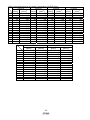
10. Initial setting value per actuator................................................................................................... 48
10.1 Initial setting value of LEF series ........................................................................................... 48
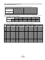
10.2 Initial setting value of LEH series........................................................................................... 50
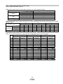
10.3 Initial setting value of LES series........................................................................................... 53
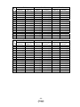
10.4 Initial setting value of LEY series ........................................................................................... 54
10.5 Initial setting value of LER series........................................................................................... 56
10.6 Initial setting value of LEP series ........................................................................................... 57
10.7 Initial setting value of LEL series ........................................................................................... 58
11. Options ........................................................................................................................................ 59
11.1 Actuator cable [5m or less]..................................................................................................... 59
11.2 Actuator cable [8 to 20m] ....................................................................................................... 59
11.3 Actuator cable (for sensor / lock) [5m or less] ................................................................. 60
11.4 Actuator cable (for sensor / lock)[8 to 20m]...................................................................... 60
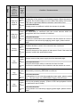
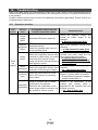
12. Alarm detection ........................................................................................................................... 61
12.1 Alarm group output ................................................................................................................ 61
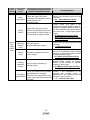
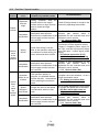
12.2 Alarm Content・Countermeasure ......................................................................................... 62
13. Wiring of cables/Common precautions .......................................................................................... 65
14. Electric actuators/Common precautions ........................................................................................ 66
14.1 Design and selection ............................................................................................................. 66
14.2 Mounting ................................................................................................................................ 67
14.3 Handling................................................................................................................................. 67
14.4 Operating environment .......................................................................................................... 69
14.5 Maintenance .......................................................................................................................... 69
14.6 Precautions for actuator with lock.......................................................................................... 70
15. Controller and its peripheral devices / Specific product precautions.............................................. 71
15.1 Design and selection ............................................................................................................. 71
15.2 Handling................................................................................................................................. 71
15.3 Installation.............................................................................................................................. 72
15.4 Wiring of cables/Common precautions .................................................................................. 72
15.5 Power supply ......................................................................................................................... 73
15.6 Grounding .............................................................................................................................. 73
15.7 Maintenace ............................................................................................................................ 73
16. Troubleshooting........................................................................................................................... 74
16.1 Operation troubles ................................................................................................................. 74
16.2 Position / Speed troubles ....................................................................................................... 76
-2-
LECP1 Series / Controller
Safety Instructions
These safety instructions are intended to prevent hazardous situations and/or equipment damage.
These instructions indicate the level of potential hazard with the labels of “Caution,” “Warning” or “Danger.”
They are all important notes for safety and must be followed in addition to International Standards (ISO/IEC),
Japan Industrial Standards (JIS)*1) and other safety regulations*2).
*1) ISO 4414: Pneumatic fluid power -- General rules relating to systems
ISO 4413: Hydraulic fluid power -- General rules relating to systems
IEC 60204-1: Safety of machinery -- Electrical equipment of machines (Part 1: General requirements)
ISO 10218-1992: Manipulating industrial robots -- Safety
JIS B 8370: General rules for pneumatic equipment.
JIS B 8361: General rules for hydraulic equipment.
JIS B 9960-1: Safety of machinery – Electrical equipment for machines. (Part 1: General requirements)
JIS B 8433-1993: Manipulating industrial robots - Safety. etc.
*2) Labor Safety and Sanitation Law, etc.
Caution
Operator error could result in injury or equipment damage.
Warning
Operator error could result in serious injury or loss of life.
Danger
In extreme conditions, there is a possibility of serious injury or loss of life.
Warning
1. The compatibility of the product is the responsibility of the person who designs the equipment or
decides its specifications.
Since the product specified here is used under various operating conditions, its compatibility with specific
equipment must be decided by the person who designs the equipment or decides its specifications based on
necessary analysis and test results.
The expected performance and safety assurance of the equipment will be the responsibility of the person who
has determined its compatibility with the product.
This person should also continuously review all specifications of the product referring to its latest catalog
information, with a view to giving due consideration to any possibility of equipment failure when configuring the
equipment.
2. Only personnel with appropriate training should operate machinery and equipment.
The product specified here may become unsafe if handled incorrectly.
The assembly, operation and maintenance of machines or equipment including our products must be
performed by an operator who is appropriately trained and experienced.
3. Do not service or attempt to remove product and machinery/equipment until safety is confirmed.
The inspection and maintenance of machinery/equipment should only be performed after measures to prevent
falling or runaway of the driven objects have been confirmed.
When the product is to be removed, confirm that the safety measures as mentioned above are implemented
and the power from any appropriate source is cut, and read and understand the specific product precautions
of all relevant products carefully.
Before machinery/equipment is restarted, take measures to prevent unexpected operation and malfunction.
4. Contact SMC beforehand and take special consideration of safety measures if the product is to
be used in any of the following conditions.
1) Conditions and environments outside of the given specifications, or use outdoors or in a place exposed to
direct sunlight.
2) Installation on equipment in conjunction with atomic energy, railways, air navigation, space, shipping,
vehicles, military, medical treatment, combustion and recreation, or equipment in contact with food and
beverages, emergency stop circuits, clutch and brake circuits in press applications, safety equipment or
other applications unsuitable for the standard specifications described in the product catalog.
3) An application which could have negative effects on people, property, or animals requiring special safety
analysis.
4) Use in an interlock circuit, which requires the provision of double interlock for possible failure by using a
mechanical protective function, and periodical checks to confirm proper operation.
-3-
LECP1 Series / Controller
Safety Instructions
Caution
The product is provided for use in manufacturing industries.
The product herein described is basically provided for peaceful use in manufacturing industries.
If considering using the product in other industries, consult SMC beforehand and exchange
specifications or a contract if necessary.
If anything is unclear, contact your nearest sales branch.
Limited warranty and Disclaimer/Compliance Requirements
The product used is subject to the following “Limited warranty and Disclaimer” and “Compliance
Requirements”.
Read and accept them before using the product.
Limited warranty and Disclaimer
The warranty period of the product is 1 year in service or 1.5 years after the product is
delivered.*3)
Also, the product may have specified durability, running distance or replacement parts. Please
consult your nearest sales branch.
For any failure or damage reported within the warranty period which is clearly our
responsibility, a replacement product or necessary parts will be provided.
This limited warranty applies only to our product independently, and not to any other damage
incurred due to the failure of the product.
Prior to using SMC products, please read and understand the warranty terms and disclaimers
noted in the specified catalog for the particular products.
*3) Vacuum pads are excluded from this 1 year warranty.
A vacuum pad is a consumable part, so it is warranted for a year after it is delivered.
Also, even within the warranty period, the wear of a product due to the use of the vacuum pad or
failure due to the deterioration of rubber material are not covered by the limited warranty.
Compliance Requirements
When the product is exported, strictly follow the laws required by the Ministry of Economy, Trade and
Industry (Foreign Exchange and Foreign Trade Control Law).
-4-
2. Outlines of Product
2.1 Features
Features of the controller.
Actuator control
Servo control enables the positioning and the operation with a specified thrust of
the actuator.
Operation and settings are available with the controller.
Settings can be altered and operation can be fun from the controller. Adjustments of the
position, speed, acceleration and test runs are available without the teaching box, PC, and
PLC.
Operation with specified thrust
The holding force and pushing force of the actuator can be controlled in three steps.
Separated power supply input
Power supply input is separated into the motor power supply and control power supply.
Even if the power supply for the motor is turned off, the information of the encoder position is
not lost while the control power supply is on, and parallel I/O control is available.
Automatic sequence function of the returning to origin position
Returning to origin position is available through I/O signal combination.
Alarm detection
Abnormal conditions are self-detected.
Alarms are displayed by LED on the controller and
abnormal conditions are output to the outside by the parallel I/O terminal.
14 points positioning / pushing is available
Through the combination of parallel I/O inputs, 14 points (position number 1 to 14(E)) of
positioning / pushing are available. The speed and acceleration of the positioning can be set
by the switch for each operating direction.
Data input method
Parameter settings, test runs, and alarm resets can be performed by the
controller.
Caution
When the device is set up or failure occurs, please refer to the operation manual of the actuator as
well as this operation manual.
* Keep this operation manual accessible so it can be referred to when necessary.
S
-5-
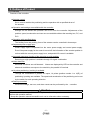
2.2
How to Order
How to order is shown below.
Controller
LECP1N□-□
Controller
P
Actuator
Applicable motor
Step motor (servo DC24V)
1
Model
(Enter from the actuator model "LE" to ”stroke”)
Ex: LEHZ10LK2-4AF-R11N1
Enter "LEHZ10LK2-4"
Step data
14 points (Programless)
Parallel input / output type
N
NPN type
P
PNP type
I/O cable length
Nil
1
3
5
No cable
1.5m
3m
5m
* Power cable length is 1.5m only
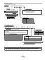
Actuator + Controller
LEHZ10LK2-4AF-R11N1
Actuator type
I/O cable length*
Fill in How to Order referring to How to Order of the catalog
of Actuators.
Please refer to the table below for the applicable actuators.
Ex. :LEHZ10LK2-4AF-R11N1
Applicable actuators
Electric gripper LEH Series
Electric slide table LES Series
Electric actuator / Rod type LEY Series
Electric actuator / Slider type LEF Series
Electric actuator / Rotary type LER Series
Nil
1
3
5
No cable
1.5m
3m
5m
Controller
Nil
1N
1P
No controller*
With programless controller (NPN)
With programless controller(PNP)
* If the actuator is ordered without the controller, the
I/O cable type is not available.
LECP6 series I/O cables cannot be used
due to different specification.
Caution
Single controllers are also shipped after setting the actuator specification parameters.
Confirm the combination of the controller and the actuator is correct.
-6-
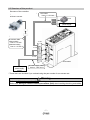
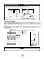
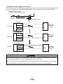
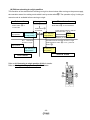
2.3 Structure of the product
Structure of the controller.
*
*
● Electric actuator
●I/O cable
Part no.: LEC-CK4-*
PLC
Input/output signal
power supply
*
● Actuator cable
[Robot cable]
Part no.: LE-CP-*
[Standard cable]
Part no. :LE-CP-*S
To CN4
To CN3
To CN2
●Controller
To
CN1
Controller input
power supply
24VDC
● Power supply cable
Part no.: LEC-CK1-1
* These items are included if you ordered using the part number for an actuator set.
Warning
Refer to 4. External connection (P.15) for wiring.
Refer to 13. Wiring of cables/Common precautions (P.65) when handling the wiring and cables.
-7-
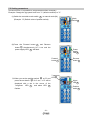
2.4 Procedure (How to start the actuator)
Install, wire, set and operate the controller referring to the procedure below when the product is used
for the first time.
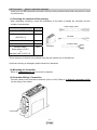
(1) Checking the contents of the package
After unpacking everything, check the description on the label to identify the controller and the
number of accessories.
Part’s name
Quantity
Controller (LECP1□□-□)
1 pcs.
Power supply cable
1 pcs.
Power supply cable
I/O cable
(LEC-CK1-1)
I/O cable *(LEC-CK4-□)
1 pcs.
Actuator *
1 pcs.
Actuator cable *
Robot cable: LE-CP-□
or
Standard cable: LE-CP-□S
1 pcs.
Controller
Actuator cable
* These items are included if you ordered using the part number for an actuator set.
If parts are missing or damaged, please contact our distributor.
(2) Mounting the Controller
Refer to 3.4 Mounting (P. 13) to mount the controller.
(3) Controller Wiring / Connection
Connect cables to the controller connectors (CN1 to CN4). Refer to 4. External connection (P.15)
for the wiring of the cables.
Connectors
-8-
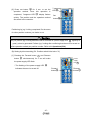
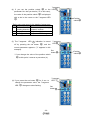
(4) Power supply ON
Alarm check
Supply power 24V DC.
Controller
Description
LED turns on
Condition
PWR
Green LED is on
Servo is on
Green LED is flashing
Servo is turned off
Red
Alarm is generated
ALARM
If the conditions are normal, the LED[PWR] at the front of the controller switches from a flashing to a
solid light. The servo is turned on if the conditions are normal. If the LED[ALM] on the front surface of
the controller turns red, the alarm goes off.
Caution
When an alarm is generated
Confirm the content of the alarm with 7-segment LED of the controller or I/O output.
Eliminate the cause referring to 12.
Alarm detection (P.61).
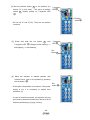
(5) Data (Operation pattern) setting
Set the stop position, speed, acceleration, and deceleration for the operating directions with the
buttons and switches on the controller. Operations other than position setting, jog/inching can be
performed after returning to origin position. Refer to 7. Setting method (P.23) for the details of
settings.
(6) Test run
Test run is performed with the buttons and switches of the controller or I/O signal. Refer to 7.1
Setting procedure (P.24) and 6.3 Parallel input / output signal (P.20) for details.
-9-
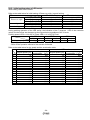
3. Specifications
3.1 Basic specifications
Basic specifications of the product.
Item
Specifications
Controlled motor
Parallel input
Step motor(servo 24VDC)
Power supply voltage: 24VDC±10%
Max. current consumption: Rated 3.2A (Peak 5A)(*2)
[Includes the motor power supply, control power supply, stop,
unlocking]
Input 6 points (Photo coupler insulation)
Parallel output
Output 6 points (Photo coupler insulation)
Stop points
Serial communication
14 points(Location number 1 to 14(E))
Incremental A/B phase
Pulse number: 800 pulse/rev
RS485 (Complies with Modbus protocol)
Memory
EEPROM
LED display
LED(Green/Red) 1 for each
1 digit, 7-segment display (red)
Figures are expressed in hexadecimal (10 to 15 in decimal number are
expressed as A to F)
With unlocking terminal
I/O cable: 5m or less
Actuator cable: 20m or less
Air-cooling type
Power supply
specification (*1)
Controlled encoder
7-segment LED display
(*3)
Locking
Cable length
Cooling method
Operating temperature
range
Operating humidity range
Storage
temperature
range
Storage humidity range
0 to 40°C(No condensation, no freezing)
90%RH or less (No condensation)
-10 to 60°C(No condensation, no freezing)
90%RH or less (No condensation)
Insulation resistance
Between the case (Heat Sink) and SG terminal: 50MΩ(500VDC)
Weight
130g
*1) Do not use inrush current suppressor types as the power supply for the controller input.
*2) Power consumption depends on actuator. Please refer to the operation manual of actuators
for details.
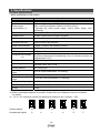
*3)"10" to "15" in decimal number are displayed as follows in the 7-segment LED
Decimal display
10
11
12
13
14
15
Hexadecimal display
A
b
c
d
E
F
- 10 -
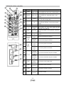
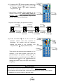
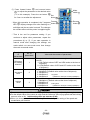
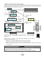
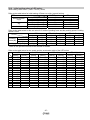
3.2 Details of the controller
e
○
f
○
g
○
i
○
k
○
m
○
d
○
c
○
No.
Display
a
○
a
○
PWR
b
○
b
○
ALM
Details
Description
Power
supply LED
Power supply ON/No alarm
:Green turns on
Power supply ON/servo OFF :Green flashes
Power supply ON/With alarm :Red turns on
Alarm LED
Power supply ON/Parameter setting: Red
flashes
Change and protection of the mode SW (Close
c
○
h
○
―
Cover
j
○
d
○
―
FG
mounting the controller. Connect the grounding
e
○
―
Mode switch
Switch the mode(Manual mode <-> Auto mode)
f
○
―
g
○
SET
h
○
―
the cover after changing SW)
Frame ground (Tighten the bolt with the nut when
cable.)
l
○
n
○
i
○
j
○
r
○
q
○
k
○
7-segment
LED
Set button
Position
switch
Forward
MANU
AL
button
Reverse
button
Stop position, the value set by
h
○
and alarm
information are displayed.
Decide the settings or drive operation in Manual
mode.
Assign the position to drive(1 to 14), and the origin
position.
Perform forward jog and inching.
Perform reverse jog and inching.
Forward
speed
SP
EED
l
○
16 forward speeds are available.
switch
Reverse
speed
16 reverse speeds are available
switch
Forward
m
○
p
○
acceleration
ACCEL
n
○
16 forward acceleration steps are available.
switch
Reverse
acceleration
16 reverse acceleration steps are available.
switch
o
○
o
○
Power
CN1
supply
Connect the power supply cable
connector
p
○
CN2
q
○
CN3
r
○
CN4
Motor driving
connector
Encoder
connector
I/O
connector
- 11 -
Connect the motor connector.
Connect the encoder connector
Connect I/O cable
Caution
Use a flat blade watchmaker's screwdriver of the size shown below when changing position
switch ○
h and the set value of the speed/acceleration switch
k
○
to ○
n
<Size>
End width
L :2.0 to 2.4 [mm]
End thickness W :0.5 to 0.6 [mm]
L
W
Magnified view of the end of the flat blade screwdriver
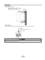
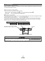
3.3 Outer dimensions
The appearance of the product is shown below.
(1)Mounting screw (LECP1□□-□)
- 12 -
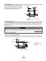
3.4 Mounting
(1) Mounting
Details of the controller.
Mounting screw (LECP1□□-□)
(Mounting with two M4 screws)
Grounding
cable
Mounting
direction
Mounting
direction
(2) Grounding
Tighten the bolt with the nut when mounting the ground cable as shown below.
M4 screw
Cable with crimping terminal
Serrated washer
Controller
Caution
M4 screws, cable with crimping terminal and serrated washer are prepared by customer.
Ground the controller to reduce noise.
- 13 -
Caution
(1) Grounding shall be done by dedicated cable. Grounding with the ground resistance of 100Ω or less.
(2) The cross sectional area of the grounding cable shall be 2mm2 or more.
Grounding location shall be in the vicinity of the controller. Keep the grounding cable short.
Controller
Other
equipment
Controller
Other
equipment
Ground with
the resistance
less than 100
ohm
Dedicated grounding --- Good
Shared grounding --- Not acceptable
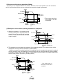
(3) Location for mounting
Select the size and the installation style so that the surrounding temperature of the controller is 40oC or less.
Mount the controller vertically on the wall with 60mm or more of space on top and bottom of the controller for
connecting and disconnecting of the cable.
Keep 60mm or more between the front of the controller and the cover (lid) so that buttons and switches can be
operated.
Keep enough space around the controller so that the operating temperature of the controller stays within the
specification range.
Avoid mounting on a panel where a vibration source such as large size electromagnetic contactor or circuit fuse
breaker is also mounted.
Usually : 0mm
Specified product number(LE□□):10mm or more
Door (Lid)
Body size 25
or more
LEH is excluded
30mm or more
Controller
Controller
60mm or more
(Keep the space for
connecting/ disconnecting
the cable)
60mm or more
(Keep enough
space so that
buttons
and
switches can be
operated.)
Caution
When there are dents, bumps or warping on the mounting surface of the controller, excessive
force can be applied to the case, which can cause failure. Mount on a flat surface.
- 14 -
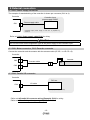
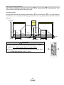
4. External connection
4. 1 CN1: Power supply connector
The example of standard wiring of the controller is shown per connector (CN1 to 4).
Controller
CN1
Controller input
power supply 24VDC
Power supply cable
(Controller input power supply of 24V DC is prepared by
customer.
Refer to 5. CN1: Power supply cable(P.16) for wiring.
Caution
Do not use inrush current suppressor type as the power supply for the controller input.
4. 2 CN2: Motor connector, CN3: Encoder connector
Connect the controller and the actuator with the actuator cable (LE-CP-□ or LE-CP-□S).
Controller
CN3
Actuator
Actuator cable
Motor
CN2
4. 3 CN4: Parallel I/O connector
Controller
PLC etc.
CN4
I/O cable
(PLC is prepared by customer)
* Refer to 6.4 Parallel I/O connector wiring (Example) (P.22) for wiring.
* Refer to 6.3 Parallel input / output signal (P.20) for details
- 15 -
5. CN1: Power supply cable
5. 1 Power supply cable specification
Included power supply cable specification is shown below.
Power supply cable (LEC-CK1-1)
(15.8)
6.0)
(60)
(35)
(10.5)
(L)
(13.3)
Item
Connector
Specifications
Manufacturer: J.S.T. Mfg. Co.,Ltd.
Product number :VHR-4N
Cross sectional
area of the cable
Length (L)
AWG20
LEC-CK1-1:1.5m only
Termin
al
Color of
covered wire
Function
Functional explanation
0V
Blue
Common
supply (-)
M24V
White
Power
supply
motor (+)
C24V
Brown
Power supply (+) for
Power supply for the controller
the controller
BK
RLS
Black
Unlocking (+)
power Common for motor supply, controller supply, and
brake release.
of
Power for the motor supplied through the controller
Unlocks the brake for maintenance
- 16 -
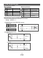
5. 2 Power supply cable specification
Referring to (1) to (4), connect the power supply cable included in accessories to the controller input
power supply 24VDC and insert it to the controller CN1 power supply connector.
(1) Wiring of power supply
Connect the plus (+) of the controller input power supply 24VDC to C24V terminal of the power supply
cable, and connect the minus (-) to 0V terminal.
0V
0V
M24V
C24V
Controller
24V
Controller
input power
supply
BK RLS
Caution
Do not use inrush current suppressor type as the power supply (24VDC) for the controller input.
(2) Wiring for the switch for forced unlocking
Install unlocking switch for the adjustment or recovery during emergency of the locking actuator.
* Switch (24V DC, contact capacity 0.5A or more) is provided by customer.
Connect one of unlocking switch terminals to the input power supply for the controller, and the other to
BK RLS terminal of the power supply plug. Locking mechanism is released by closing the switch.
0V
0V
M24V
Controller
24V
C24V
Controller
input power
supply
BK RLS
Switch for forced
unlocking
Caution
It is unnecessary to connect BK RLS terminal when the actuator does not have locking mechanism.
Connect BK RLS terminal only when releasing the lock at servo OFF or STOP is ON is needed.
(3) Wiring for the stop switch
Stop switch is necessary.
0V
0V
Controller
M24V
24V
C24V
Controller
input power
supply
BK RLS
The actuator stops when M24V is turned off. When M24V is turned off in the actuator operation, the
alarm is detected.
When the STOP signal is turned on, the actuator stops. At this time, the alarm is not detected.
- 17 -
(4) Stop the power supply for the motor
If it is necessary to shut off the power supply for the motor from outside, connect the relay between the
input power supply for the controller 24VDC and the power supply plug for the controller M24V.
【Example of the circuit】
24VDC Reset switch for stop
0V
Ry
STOP
switch
Ry
Surge suppressor
1st ptoduct
0V
Controller
M24V
C24V
0V
Ry
24V
Controller
input power
supply
BK RLS
2nd ptoduct
0V
0V
Controller
M24V
C24V
Ry
24V
Controller
input power
supply
BK RLS
3rd ptoduct
0V
Controller
M24V
C24V
0V
Ry
24V
BK RLS
Controller
input power
supply
Warning
● Do not perform returning to origin position neither drive operation when the the power supply
for the motor (M24V) is shut off, otherwise alarm will be generated.
● The controller does not recognize the correct origin position with the command for returning to
the origin position at the time of the shutoff of the power supply for the motor (M24V).
- 18 -
6. CN4: Parallel I/O cable
6.1 Paralles input / output
■Output specifications
■Input specifications
NO.
Item
1
Input circuit
2
3
No. of inputs
Voltage
Input current
at ON
Input current /
voltage at OFF
4
5
Specifications
NO.
Internal circuit and the
photo coupler insulation
6 points
DC24V±10%
1
Output circuit
2
No. of output
Maximum voltage
between terminals
Maximum
output
current
Saturation voltage
between terminals
3
3.5mA±20%(at DC24V)
4
1.5mA or less of current
11V or less of voltage
Item
5
Specifications
Internal circuit and the
photo coupler insulation
6 opints
DC30V
10mA
2.0V (Maximum)
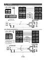
6.2 Parallel input / output circuit (NPN, PNP)
There are two types of parallel input / output types for this controller.
NPN type (LECP1N□□-□)
PNP type (LECP1P□□-□)
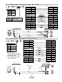
(1) Parallel I/O input circuit (NPN, PNP common)
NPN TYPE
Outside
(a)
「COM+」〈1〉
(b)
IN0〈9〉~STOP〈14〉
Inside of the controller
(a)
PNP TYPE
(b)
(a)
「COM-」〈2〉
(b)
IN0〈9〉~STOP〈14〉
(2) Parallel I/O output circuit
NPN TYPE
Inside of the controller
Outside
OUT0〈3〉
~ALARM〈8〉
「COM-」
〈2〉
PNP TYPE
Inside of the controller
Outside
「COM+」
〈1〉
OUT0〈3〉
~ALARM〈8〉
- 19 -
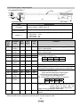
6.3 Parallel input / output signal
I/O cable(LEC-CK4-□)
(16)
( 7.9)
(10)
(11)
(30)
(60)
(L)
PLC side
Controller side
Item
Connector
Cross sectional
area of the cable
Length (L)
Termi
nal
No.
1
2
3
4
5
6
7
8
Specifications
Manufacturer: J.S.T. Mfg. Co.,Ltd.Manufacturer: J.S.T. Mfg. Co.,Ltd.
Product number :PADP-14V-1-S
AWG26
The suffix of the part number (1,3,5) specifies the length.
LEC-CK4-1: 1.5m
LEC-CK4-3: 3m
LEC-CK4-5: 5m
Insulation
color
Dot
Mark
Dot
color
Func
tion
Contents
Light
brown
Light
brown
Yellow
Yellow
Light
green
Light
green
Gray
Gray
■
Black
COM+
■
Red
COM-
■
■
■
Black
Red
Black
OUT0
OUT1
OUT2
Connect the 24V side of the power supply (24VDC) for
input / output signal.
Connect the 0V side of the power supply (24VDC) for
input / output signal.
Operation completion output (Output with the
combination of OUT0 to 3)
OUT3 OUT2 OUT1 OUT0
OFF
OFF
ON
ON
■
Red
OUT3
■
■
Black
Red
BUSY
ALARM
BUSY signal (Output during operation)
ALARM signal N.C.
(Turned off during alarm or when servo is turned off)
9
White
■
Black
IN0
・Operation command input
(Input with thecombination of IN0 to IN3)
10
White
■
Red
IN1
・Input return to origin position command
11
Light
■■
Black
IN2
(Turn on IN0 to 3 simultaneously)
brown
Ex. (Commands position number 5 to operate)
12
Light
■■
Red
IN3
IN3
IN2
IN1
IN0
brown
OFF
ON
OFF ON
Interruption
or
alarm
reset
13
Yellow
■■
Black
RESET
During operation: The speed is reduced from the point
where signal is input until the
actuator stops. (Servo stays ON)
Alarm is being generated: Alarm reset
14
Yellow
■■
Red
STOP STOP command (Sudden deceleration to turn off
servo)
* Parallel I/O signal is valid in auto mode. STOP signal is valid in auto mode and manual mode.
While the test function operates at manual mode, only the output is valid.
- 20 -
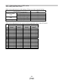
The change of I/O output signal under the condition of controller at auto mode.
Output signal
Condition of the controller
OUT0
OUT1
OUT2
OUT3 BUSY
OFF
OFF
OFF
OFF
OFF
Supply of power
After supplying power and at the
OFF
OFF
OFF
OFF
OFF
stop before returning to origin
position
During the returning to origin
OFF
OFF
OFF
OFF
ON
position, positioning, and pushing
operation.
When return to origin position is
ON
ON
ON
ON
OFF
completed.
During the return to origin
*1
*1
*1
*1
OFF
position, positioning, and pushing
operation.
OFF
OFF
OFF
OFF
OFF
Stopped by RESET command
OFF
OFF
OFF
OFF
OFF
Stopped by STOP command
OFF
*2
*2
*2
OFF
When alarm is generated
*1 ON, OFF of OUT0 to 3 depends on the target position
*2 ON and OFF of OUT0 to 3 depends on the alarm group.
ALARM
OFF
ON
ON
ON
ON
ON
OFF
OFF
There is no servo ON signal with this controller. The servo turns off when conditions to turn off the
servo are satisfied. Refer to 8.5 Servo ON (P.43) for details.
Caution
● Signal is not output from I/O right after switching from manual mode to auto mode. Output from
I/O is made after the next input of operation command.
● Output from I/O is not made if switching from auto mode to manual mode.
- 21 -
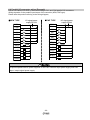
6.4 Parallel I/O connector wiring (Example)
Use an I/O cable (LEC-CK4-□) when connecting to PLC and CN4 parallel I/O connectors.
Wiring depends on the parallel input/output of the controller (NPN, PNP type).
Please wire the product referring to the wiring diagram,
■NPN TYPE
I/O signal power
supply DC24V
■PNP TYPE
COM +
COM +
COM -
COM -
IN0
IN0
IN1
IN1
IN2
IN2
IN3
IN3
RESET
RESET
STOP
STOP
OUT0
I/O signal power
supply DC24V
Load
OUT0
OUT1
OUT1
OUT2
OUT2
OUT3
OUT3
BUSY
BUSY
ALARM
ALARM
Load
Caution
Prepare separate 24VDC power supplies for the CN1 controller input power supply and CN4
input / output signal power supply.
- 22 -
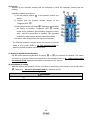
7. Setting method
It is necessary to set the stop position and operation method using the controller in order to move the
actuator to the specified position. Set data is stored in the memory in the controller
h . ("1" to "9", "A" to "E") is
Up to 14 points can be set. Set "1" to "14" with the position switch ○
displayed in hexadecimal on the 7-segment
LED
f .
○
c
f ○
○
e
○
There are 2 types of modes on the controller (manual mode, auto mode).
Setting and operating methods are different. Mode is switched by mode
Switch ○
e .
Upper part of the right figure(M) : Manual mode
Lower part of the right figure(A) : Auto mode
g
○
h
○
i
○
j
○
Caution
Close the cover
c
○
after the switching the mode to avoid
unexpected mode changes.
Manual mode(M)
Auto mode(A)
O
X
Setting of stop position (step
data)
Setting of Speed and
Acceleration
Setting of operation method
Setting parameters
Controller operation using the
button
Operation from parallel I/O
Positioning operation
Pushing operation
Output to parallel I/O
Check the presence of alarm
Check the content of alarm
How to release the alarm
Press set button ○
g
O
O
∆(Only in speed
adjustment)*2
X
X
O
X
X
O
∆(Test function only)*1
∆(Test function only)*1
O
O
O
O
O
O
O
O
Turn on RESET or
g
press set button ○
O
Turn off Servo Press
Forward button ○
i
and Reverse button
Servo OFF method
Turn on STOP
j
simultaneously
for
○
3 sec.
*1 Refer to 7.4 Test function (P.38) for details of test function.
*2 Refer to 7.3 Controller modes (P.34) for details of the adjustment of the speed.
- 23 -
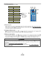
7.1 Setting procedure
Follow the procedure below for setting.
(1)Supply of power
f ○
e ○
c
○
(2)Changes to Manual mode
a
○
(3)Return to origin position
(4)Setting of position
(5)Setting of operation method
(6)Test run
Repeat the
same
procedure
for all points
you
would
like to set.
g
○
h
○
(7)Setting speed / acceleration
(8)Setting completed
(1)Supply of power
Apply 24VDC to the power supply for the power line and the signal line. After applying the power,
confirm that the power supply LED ○
a lights green (=Servo ON). Refer to 8.5 Servo ON (P.43)
if the power supply LED ○
a flashes green.
(2) Changes to Manual mode
Switch the controller mode switch ○
e to manual mode (M). In manual mode, the 7-segment LED
f indicates the value of the position switch ○
h with high speed flashing.
○
(3) Return to origin position
f display is changed to "F" by setting the position switch ○
h
Confirm that the 7-segment LED ○
to "15", then press the set button ○
g to start the return to origin. When the return to origin is
completed, the display of the 7-segment LED ○
f changes changes from flashing to solid.
Caution
● If you perform return to origin before the servo is turned on (Power supply LED ○
a lights up in
green) an alarm will be generated. Perform the return to origin after confirming that the servo is
turned on.
● Refer to 8.1 Returning to origin position(P.39) for details.
● The direction of return to home depends on the actuator. Refer to 10. Initial setting value
per actuator (P.48).
- 24 -
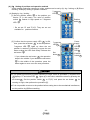
(4), (5) Setting of position and operation method
At the manual mode after returning to origin, position can be set by (A) Jog / inching or (B) Direct
teaching. Example) Setting of position number 3
7-segment
f
LED○
(A) Setting by Jog / inching
[1] Set the position switch ○
h to the position you
desire ("3" in this case). The value of position
Position
switch ○
h flashes in high speed on 7-segment
h
switch○
LED ○
f
* Do not set "0" and "F(15)", They are not not
available for
position numbers.
[2] Confirm that the power supply LED ○
a is ON,
then, press the set button ○
g to the set position.
7-segment LED ○
f lights up when the set
position is reached. Continuing to press the set
button makes the LED flash slowly. Release the
set button ○
g .
* If you release the set button ○
g the operation
stops in the middle. If you release the set button
g in the middle of the operation, press the
○
button again to move on to the next procedure.
7-segment
f
LED○
Set
g
button○
Power
supply
a
LED○
Alarm
b
LED○
Position
h
switch○
Caution
● If you perform procedure [2] before returning to origin, alarm is generated (7-segment LED
f displays "C" and alarm LED ○
b lights up) In this case, release the alarm by pressing the
○
g . Set the position switch ○
h to "F(15)" and press the set button ○
g for
set button○
retuning to origin, then perform the procedure [2].
● If it is not possible to return to the position before setting due to the mechanical interference,
set the position by (B)Direct teaching.
- 25 -
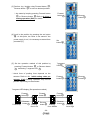
[3] Perform Jog / inching using Forward button ○
i ,
Reverse button ○
j to move to desired position.
* Jog starts by keeping pressing Forward button
i
○
or Reverse button
Forward
i
button○
j .Refer to 8.4 Jog /
○
Reverse
j
button○
inching operation (P.42) for details.
[4] Lock in the position by pressing the set button
g .
○
At this point, the value is not stored if the
power supply is cut, it is necessary to started from
procedure [1].
[5] Set the operation method of this position by
pressing Forward button
j
○
i
○
or Reverse button
monitoring 7-segment LED
Set
g
button○
7-segment
f
LED○
f
○
* Actual force of pushing force depends on the
actuator. Refer to 10.
Initial setting value per
actuator (P.48) Pushing operation may not be
Forward
i
button○
Reverse
j
button○
possible depending on the actuator.
7-segment LED display (Set operation method)
Forward
button○
i
Positioning
Reverse
j
button○
Pushing
force Low
Forward
i
button○
Forward
i
button○
Reverse
button○
j
Pushing
force Middle
- 26 -
Reverse
j
button○
Pushing
force High
[6] Press set button
operation
method.
g
○
for 2 sec. to set the
Once
completed, 7-segment LED
this
f
○
operation
is
display flashes
quickly. The position and the operation method
are stored in the controller.
7-segment
f
LED○
Set
g
button○
Positioning by jog / inching completed. Do the same
for other position numbers you desire to set.
Caution
● If you perform jog / inching before the servo is turned on (Power supply LED ○
a lights up in
green), alarm is generated. Perform jog / inching after confirming that the servo is turned on.
● Set operation method per position number. Refer to 8. Operations(P.39).
(B) Setting by direct teaching (Ex. Position switch initial value "4")
[1] Pressing the Forward button
button
j
○
i
○
and Reverse
simultaneously for 3 sec will make
Power
supply
the power supply LED flash.
LED
a
○
a
* The flashing of the power supply LED ○
indicates the servo is turned off.
Forward
i
button○
- 27 -
Reverse
j
button○
[2] Set the position switch ○
h to the position you
desire ("3" in this case).
switch
h
○
The value of position
7-segment
f
LED○
flashes quickly on 7-segment LED
f .
○
Position
h
switch○
* Do not set "0" and "F(15)", They are not position
numbers.
[3] Press and hold the set button
7-segment LED
f
○
g
○
until
changes quick flashing -->
7-segment
f
LED○
solid lighting --> slow flashing.
Set
g
button○
[4] Move the actuator to desired position with
external force. Lock in the position by pressing
the set button ○
g .
* At this point, the position is not stored, If the power
supply is cut, it is necessary to started from
procedure [1].
* In case of small lead screws, the actuator may not
be moved by external forced even if the servo is off.
Perform positioning by (A) jog / inching
- 28 -
Set
g
button○
[5] 7-segment LED ○
f , Set the operation method of
this position by pressing the Forward button ○
i
or Reverse button ○
j
while monitoring
7-segment LED ○
f .
* Actual force of pushing force depends on the
actuator. Refer to 10.
Initial setting value per
actuator (P.48) Pushing operation may not be
7-segment
f
LED○
Forward
i
button○
Reverse
j
button○
possible depending on the actuator.
7-segment LED display (Set operation method)
Forward
button○
i
Positioning
Reverse
j
button○
Pushing
force Low
[6] Press set button
operation
method.
Forward
i
button○
Forward
i
button○
g
○
Reverse
button○
j
Pushing
force Middle
for 2 sec. to set the
Once
this
operation
is
Reverse
j
button○
Pushing
force High
7-segment
f
LED○
completed, the position and the operation
method
are
stored in
7-segment LED
f
○
the
controller,
and
display flashes quickly.
Set
g
button○
Forward
i
button○
That is all for the setting by direct teaching. If you
continue to set other position, start from the
procedure [2]. If you perform setting with Jog /
Inching or test run, press Forward button
Reverse button
j
○
i
○
and
for 3 sec. simultaneously to
change the power supply LED ○
a from flashing
to lighting.
Caution
●Set operation method per position number. Refer to 8. Operations (P.39).
●The actuators with a smaller lead, it may not be moved by the external force. Perform
positioning by (A) jog / inching in previous page.
- 29 -
Power
supply
a
LED○
Reverse
j
button○
(6) Test run
Operate by the controller buttons and the switches to check the operation method and the
position.
f ○
○
e
Operation method is as follows.
c
○
1) Set the position switch ○
h to the position number you
desire.
2) Confirm that the position number flashes on the
7-segment LED
f .
○
3) Press and hold the set button○
g . Operation is kept while
the button is pressed. 7-segment LED
f
○
flashes
slowly during operation. Slow flashing changes to being
solid
when the set position is reached. This operation
confirms the stop position and the operation method.
g
○
h
○
i
○
k
○
j
○
l
○
m
○
n
○
4) Confirm other stop position with the same operation.
* For Pushing operation, check with the test function of manual
mode or auto mode. Refer to 7.4 Test function (P.38) for
details of normal operation and test function.
(7) Setting of Speed and Acceleration
Set the speed and the acceleration by switch
k
○
to ○
n per direction of actuation. The switch
can be set in 16 steps. Actual value depends on the actuator. Refer to 10.
Initial setting value
per actuator (P.48). Operation procedure is the same as (6) Test run.
(8) Completion of setting
After the setting, the operation can be controlled by switching to auto mode by the mode switch
e . Refer to 9.
○
Operation (Example) (P.44) for operation of PLC.
Caution
Close the cover
c
○
after the switching of the mode to avoid unexpected mode change.
- 30 -
7.2 Setting parameters
In manual mode, it is possible to set parameters when necessary.
Example. Change the jog speed level from "1" (default condition) to "3"
(1)Switch the controller mode switch ○
e to manual mode (M).
(Example. "4" (Default value of position switch)
(2)Press the Forward button
i
○
Mode
e
switch○
and Reverse
button ○
j simultaneously for 3 sec and the
Power
supply
LED○
a
power supply LED ○
a will flash.
Forward
button○
i
Reverse
j
button○
7-segment
f
(3)When you set the position switch ○
h at "0" and LED○
press the set button ○
g for 3 sec., a "0" will be
displayed with a dot in the corner of the
7-segment
LED
f ,
○
and alarm LED
b
○
flashes.
- 31 -
Alarm
b
LED○
Position
h
switch○
7-segment
(4) If you set the position switch ○
h to the LED○
f
parameter No. that you desire ("2" in this case),
the value of the position switch ○
h is displayed
with a dot in the corner or the 7-segment LED
Position
switch○
h
f .
○
* Refer to the next page for the details of parameters.
NO.
Description
Function
1
Reference
for Return to origin or changing
rotating direction forward / reverse
2
Jog speed level Adjust the jog speed
3
Inching level
Adjustment of inching
(5) The 7-segment
LED
f
○
indication is turned
off by pressing the set button
g ,
○
and the
7-segment
f
LED○
current parameter appears. ("1" appears in this
example).
Set
button○
g
* If you change the value of the position switch
h
○
at this point, it returns to procedure (4).
(6) If you press the set button ○
g for 2 sec. to
7-segment
f
LED ○
change the parameter value, the 7-segment
LED
f
○
changes to slow flashing.
Set
g
button○
- 32 -
Position
h
switch○
(7) Press forward button
j
○
i
○
and reverse button
("3" in this example). Press the set button ○
g
for 2 sec. to set after the adjustment.
* When this operation is completed, the 7-segment
LED
Mode
e
switch○
to adjust the parameter to the desired value
f
○
display changes from slow flashing to a
Set
g
button○
Forward
button○
i
Reverse
j
button○
solid light and the set value is stored. The changes
do not take effect until the power is supplied again.
* That is the end for parameter setting. If you
continue to adjust other parameters, repeat the
procedures (4) to (7). If you start operation in
manual mode after changing the settings, set
mode switch e to auto mode once, then change
the mode to manual mode.
Description
of
parameters
No. of
parameters
Reference
for rotating
direction
1
Jog speed
level
2
Inching
level
3
Value and the content of parameters
Change the direction of the return to origin and forward and
reverse.
1: CW (Default value of LEF and LEH series at the time of
shipment)
2: CCW(Dafault value of LES and LEY series at the time
of shipment)
Adjust the jog speed
1: Multiplier=1 (Default value at the time of shipment)
2: Multiplier=2
3: Multiplier=3
Jog speed
=(Reference value per actuator)×(Multiplier)
4: Multiplier=4
Adjust the inching amount
1: Multiplier=1 (Default value at the time of shipment)
2: Multiplier=2
3: Multiplier=3
Inching level
=(Reference value per actuator)×(Multiplier)
4: Multiplier=4
Caution
●Parameter changes take effect after turning off the power supply and turning it on again.
●For the default value of the return to origin and the reference value of jog speed and the inching
amount, refer to 10. Initial setting value per actuator (P.48).
●When you change the reference for rotating direction, change the setting of the speed and
acceleration per direction.
- 33 -
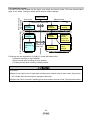
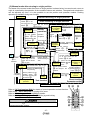
7.3 Controller modes
After retuning to origin position
Before retuning to
origin position
Controller modes are divided into two types, auto mode and manual mode. There are several status
types in one mode. The figure below shows how the status changes.
Supply power
Auto mode
Manual mode
A
Switching of mode SW
Waiting
condition
Jog /
inching
Waiting
condition
Setting of
position,
speed and
acceleration
Waiting
condition
Waiting
condition
B
Positioning
or pushing
operation by
PLC.
Switching of
mode SW
Jog /
inching
C
Positioning
using
buttons
Manual mode
Auto mode
Followings are the explanation of (A)(B)(C) circled with dashed line.
(A) Before returning to origin position
(B) Auto mode after returning to origin position
(C) Manual mode after retuning to origin position
Caution
Precaution
●Signal is not output from I/O right after switching from manual mode to auto mode. Output from
I/O is made after the next input of operation command.
●Output from I/O is not made if switching from auto mode to manual mode. (Except test function)
- 34 -
(A) Before returning to origin position
The transition of the status before returning to origin is shown below. After turning on the power supply,
the controller status is in waiting mode which is set by mode switch○
e . The operation of jog / inching at
manual mode is available before retuning to origin.
Auto mode
Mode switch
e
○
Manual mode
Supply power
Mode switch ○
e is on manual side
is
on auto side
Mode switch ○
e
Press manual forward or manual
backward button ○
i ,○
j
Jog /
inching
is switched
Before retuning to
origin position
Waiting condition
before retuning
to origin position
PLC commands
to return to origin.
After retuning to
origin position
Waiting condition
after Retuning to
origin position
Waiting condition
before Retuning
to origin position
Release the button you are pressing.
Command from the controller to return to origin
position(Position switch ○
h is "15", press set
g )
button ○
Waiting condition
after Retuning to
origin position
Manual mode
Auto mode
e
○
Refer to 8.1 Returning to origin position (P.39) for details.
Refer to 8.4 Jog / inching operation (P.42) for details.
g
○
i
○
- 35 -
h
○
j
○
(B) Auto mode after return to origin position
The status of the auto mode after return to origin position is shown below. At auto mode, only the
operation command such as I/O from PLC is accepted. Basically, position, operation method, speed
and acceleration cannot be adjusted in auto mode.
Before returning to origin position
Waiting
Stops at set
position
After returning to origin position
PLC commands
Operation
PLC
to actuate
completed
commands to
Positioning or
return to origin.
pushing operation.
PLC
commands
to actuate
switched
PLC commands
to stop
Waiting
No operation is
made for 3 min.
for all button switch.
Mode switch ○
e is
Mode switch ○
e
Waiting
is switched
f ○
e
○
Press forward and backward
button of manual button
simultaneously for 3sec.
c
○
Mode switch ○
e is
switched
PLC
commands
to actuate
Waiting for
speed adjustment
Positioning or
pushing
operation.
g
○
i
○
k
○
m
○
PLC commands
to stop
Stops at
set position
PLC
Operation completed
Commands
to actuate
h
○
j
○
l
○
n
○
Speed adjustment
Manual mode
Auto mode
Auto mode is presuming the operation by I/O from PLC. If you use buttons or
g for releasing the alarm, 7-segment LED ○
f
switches other than set button ○
indicates "L".
When the status is moved to speed adjustment, followings items are become
different from normal operation.
L display
f indication than normal operation.
(1)More dots of 7-segment LED○
(2)Speed and acceleration adjustment become available temporarily.
(3)When no operation is made for 3 min. for all buttons and switches, operation reverts back to
normal mode.
Caution
●In auto mode, changing the speed, acceleration switch values which are set by ○
k to ○
n do
not take effect except during the speed adjustment status. If returning to auto mode after
changing to manual mode, the value of the switch affects the operation.
●Close the cover c after the switching of the mode to avoid unexpected mode change.
- 36 -
(C) Manual mode after retuning to origin position
The status of the manual mode after return to origin position is shown below. In manual mode, return to
origin is controlled by the operation of the controller buttons and switches. The speed and acceleration
can be adjusted any time. It is also possible to set the position and operation method. Pushing
operation is available during test function.
Waiting
Set
Before returning to origin position
the
position
After returning to origin position
switch ○
h to "15"
and press the set
button ○
g .
Press the set button
g for 2 sec.
○
Normal
operation
Positioning
operation
e
d
o
m
o
t
u
A
Set the position
by the position
switch
h
○
and
Waiting for
the completion
of setting
Press manual
button
Operation
completed
i
○
or
j
○
g .
set button ○
Stop at set
position
Wait
ing
Mode switch
is
switched
button ○
g
for 2sec
Release the
button your
are pressing
Press the manual
buttons ○
i ,○
j
simultaneously for
3sec.
Set the position by the
position switch ○
h
and keep pressing the
set button ○
g .
Positioning or pushing
operation
Jog / inching
Release
manual
i
○
j
○
or
,
j
○
simultaneously
3sec.
i
○
for
Press the
set button
g
○
Stop before Position adjustment
adjusting
is completed
the position
Press the manual
buttons
Waiting for
setting of
operation
method
Stop after
adjusting
the position
Setting of
parameters
Set the position switch ○
h
to "0" and press the set
button ○
g for 3sec
Press the set Waiting for the
completion of
button ○
g for
setting
2sec
Adjusting the
Set the position switch
operation method
Waiting by
servo off
i or
Waiting for Press manual button ○
test
Release the button you
are pressing
Operation
completed
i ,○
j
○
Press the set
Jog / inching
Release the button
your are pressing
Waiting
Set
the
position
switch ○
h to "0" and
press the set button
g for 3sec.
○
Adjust by pressing
manual button
button
keep pressing the
Press manual
button
i or ○
j
○
e
○
Position setting (jog / inching)
j
○
h
○
and adujust
the
by pushing manual
position.
Jog /
inching
Stop after Press the set
adjusting the button g
○
position
Test function
Manual mode
Servo OFF
Direct teaching
Parameter setting
f ○
e
○
Refer to 7.4 Test function (P.38) for details of normal operation and test function.
Refer to 8.5 Servo ON (P.43) for turning off of servo.
Refer to 7.2 Setting parameters (P.31) for details.
Refer to 8.4 Jog / inching operation (P.42) for jog and inching.
Caution
Close the cover ○
c after the switching of the mode to avoid
unexpected mode change.
- 37 -
i ,○
j
button ○
Waiting for setting
of operation
method
g
○
i
○
k
○
m
○
c
○
h
○
j
○
l
○
n
○
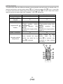
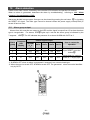
7.4 Test function
The table below shows the difference between normal operation and test function in manual mode. To
start the test function, set the position switch ○
h to "0" while the power LED ○
a is on (= servo ON)
in manual mode and the actuator stops, and press the set button ○
g for 3sec. When test function
starts, the dot on the lower right of the 7-segment LED ○
f will light up.
Availability of
pushing operation
Operation by parallel
I/O input
Output to parallel I/O
7-segment LED
f
○
display
Normal operation
X
Test function
O
X
X
X
Without dot
Target
position
setting:
Quick flashing
During
operation:
Slow
flashing
Reached the target position:
Lights up
O
With dot
Target position setting: Quick
flashing
During
operation:
Slow
flashing
Reached the target position:
Lights up
O
O
Adjustment of the
speed / acceleration
Moves
Operation method
using buttons
Moves
towards
the
towards
target position
when
the
the
target
set
g is pressed. (Not
position only while the set button ○
button○
g is pressed.
necessary to keep pressing
the button)
f ○
e
○
c
○
a
○
g
○
i
○
k
○
m
○
- 38 -
h
○
j
○
l
○
n
○
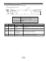
8. Operations
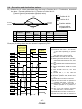
8.1 Returning to origin position
When the power is supplied, it is necessary to return to origin for positioning or pushing of the actuator.
(To ensure the position of origin)
■Input of the return to origin position
There are 2 ways for returning to origin per mode,
Manual mode : Set the position switch○
h at "15" and press the set button○
g .
Auto mode
: Turn on I/O IN0 to IN3 simultaneously.
Returning to origin position
The actuator travels to the origin position from the initial position when the power was supplied. (Origin
position depends on the actuator)・・・ "(1)" in the figure below.
The controller recognizes the actuator end when the slider travels to the actuator end and stops for
specific time. Then, the actuator travels to the opposite to the origin with low speed. The position
after the travel ("(2)" of the figure below) becomes the origin.
Return to origin input→Travels in origin position
→Stop traveling→Reverse→Origin position
Load
(Ex) Returning to origin position
Actuator
Motor
M
(2)
Origin position
(1)
Actuator end
Initial position
Caution
The direction of return to home depends on the actuator. Refer to 10.
actuator (P.48) for the default setting of the return to origin position.
- 39 -
Initial setting value per
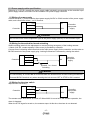
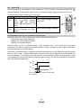
8.2 Positioning
The actuator travels to the target position at
speed and acceleration which are set per
operating direction. Operation complete signal
is output when the actuator reaches the
positioning range of the target position.
Ex. Positioning
Speed
Positioning range
Set speed
Position
Motor
Load
Actuator
M
Stop position
Target position
*The speed wave in the chart above is
simplified.
8.3 Pushing operation
Perform pushing by the set speed and acceleration with the same procedure of positioning. Start
pushing from the positioning range. Pushing is the operation in which the actuator travels from the
start position of travel to the actuator end of the opposite side with low pushing force with set
pushing thrust or less.
Caution
●At manual mode, positioning is performed even if pushing is set. (Except during test function)
● Pushing operation may not be possible depending on the actuator. Refer to 10.
Initial setting
value per actuator (P.48).
(1) Successful pushing operation
Signal to indicate the operation completion is output when the thrust is more than set pushing force
for specific period of time. Set thrust maintains to be generated even after the pushing is completed.
Speed
Set speed
Pushing speed
Position
Pushing thrust
Motor
Load
Actuator
M
Stop position Position
Position of
of pushing pushing end
start
- 40 -
* The speed wave in
the chart on the left
is simplified.
(2) Unsuccessful pushing operation (Idling)
If pushing is not completed when the actautor moves from the start position until the actuator's
end, it is pushed back at the actuator end and the completion signal is generated.
Speed
Set speed
Pushing speed
Position
Pushing thrust
Load
Motor
* The velocity wave form
in the chart on the left
is simplified.
M
Actuator
Stop
position
Position
Pushing Actuator end
of pushing
start
(3) Workpiece moves when pushing operation is completed
Speed
(i) When the actuator is in a pushing move
and the pushing force is greater than the
reaction force, the actuator will continue
to move to the end of stroke and then
output a signal.
Set speed
Position
Stop position
Motor
Load
Pushing again
Actuator
M
Stop position
Position of
Position
of pushing pushing end
start
(ii) The workpiece moves toward the opposite of the pushing direction (The reaction force of the
workpiece is too large and the actuator is pushed back)
When the actuator is pushed back after the pushing move is completed the actuator is pushed
until the reaction force and pushing force are balanced in the direction that the pushing started.
(Completion signal stays ON) An alarm is generated when the actuator is pushed back farther
than the start position of pushing. (Pushing failure)
Speed
Set speed
Pushing speed
Position
Pushing again
Motor
Load
Actuator
M
Position of
pushing end
Stop position
Position
of pushing
start
Position of
pushing
back
- 41 -
* The speed wave in
the chart on the left is
simplified.
8.4 Jog / inching operation
Jog / inching is available by pressing forward button
i
○
or reverse button
j
○
at manual mode. Jog /
inching can be performed before retuning to origin.
Operation method
Inching starts and stops by pressing forward button
i
○
or reverse button
j . If you keep pressing
○
the button for 1sec. or longer after inching, jog operation starts. Jog operation stops when the button is
released.
Position
Press
Reverse
button
Press Forward button
Stop
Jog
Press Reverse button
Stop
Stop
Stop
Jog
Time
Inching
1 sec.
Inching
1 sec. or less
1 sec.
Caution
●The travel amount of inching and jog speed depend on actuators.
Refer to 10.
Initial setting value per actuator (P.48).
●The travel amount of inching and jog speed can be changed. Refer
to 7.2 Setting parameters (P.31) for details.
- 42 -
i
○
j
○
8.5
Servo ON
Servo ON signal is not assigned to the parallel I/O of this controller. The power supply LED ○
a
changes flashing to lighting after specific period of time after power supply and the servo turns on.
The table below shows conditions for servo OFF
Conditions for servo OFF
Indication of servo OFF
Manual Alarm is generated, or servo Power supply LED a : Flashing
○
mode
OFF by pressing Forward
Alarm: OFF
i
and Reverse
button ○
button ○
j simultaneously for
3sec.
Auto
Alarm is generated, or servo Power supply LED a : Flashing
○
mode
OFF by inputting I/O STOP
signal.
a
○
i
○
j
○
8.6 Response time for the controller input signal
Response delay due to the controller input signal contains following factors.
(1)Controller input signal scan delay
(2)Delay due to input signal analysis
(3)Delay of command analysis
Process delay of PLC or scanning delay of the controller may occur. Keep the input signal
combination for 15ms or longer (the recommendation is 30ms). Initialize the input signal conditioning
the response signal to the input signal.
When one command is made by inputting several I/O simultaneously, time difference between signals
has to be 3ms or less. If the time difference is longer than 3ms, it is recognized as another signal and
start the operation. For example, when IN0 and IN1 are commanded to move to ON(position number
3) simultaneously and the time difference between them is large, only the first command is recognized
(Only IN0 input is recognized).
IN0
ON
OF
IN1
ON
OF
Time
If the time difference is large, only IN0 input
is recognized.
- 43 -
9.
9.1
Operation (Example)
Positioning / Return to origin position
Ex). If the operation pattern is Return to origin --> Position 1 --> Position 2 --> Position 1,
Forward: Speed 5, acceleration 3 (Switch value)
Reverse: Speed 9, acceleration 7 (Switch value)
(1)
Origin
Actuator end
(2)
(4)
Initial position
Reverse
Forward
Position NO.1
direction
direction
Position No.2
(3)
(1)
(2)
Start
position
Undecided
End
position
Origin
position
Operating
direction
Forward
speed
Fixed
acceler
ation
Fixed
Origin
position
NO.1
NO.2
NO.1
Reverse
9
7
Operation
method
Return to
origin
position
Positioning
NO.2
Reverse
9
7
Positioning
(3)
NO.1
Forward
5
3
Positioning
(4)
* Even for the same position number 1, the travel speed and the
acceleration may vary due to the operating direction.
Example) I/O timing chart when the actuator is operated by PLC. Please translate the boxes
(1)
Return to
origin
position
IN0
bit_0
IN1
bit_1
IN2
IN2
bit_2
IN3
bit_3
RESET
STOP
OUT0
bit_0
OUT1
bit_1
OUT2
bit_2
OUT3
bit_3
BUSY
ALARM
Speed
(2)
To NO.1
(3)
To NO.2
(4)
To NO.1
ON
OFF
ON
OFF
ON
OFF
ON
OFF
ON
OFF
ON
OFF
ON
OFF
ON
OFF
ON
OFF
ON
OFF
ON
OFF
ON
OFF
+
0
-
- 44 -
<Procedure>
[1] The servo turns on after supplying
the power, and the ALARM turns
on.
[2] Confirming that the ALARM turned
on, turn on IN0 to 3 to perform
(1)Return to origin.
[3] When return to origin starts, BUSY
turns on.
[4] Turn OFF IN0 to 3 after confirming
BUSY is ON.
[5] BUSY turns OFF when return to
origin is completed. OUT0 to 3
turns ON.
[6] When OUT0 to 3 turn ON, turn on
IN0, and start operation to the
position no,1.
[7] BUSY turns ON when the operation
starts, and OUT0 to 3 turn OFF.
[8] When BUSY turns ON, turn OFF
IN0.
[9] BUSY turns OFF when the
operation is completed, and
OUT0 turns OFF.
[10] Do the same for the travel for
position No.2 and position No.1.
9.2
Pushing operation
Ex.) If the operation pattern is Position 3 --> Position 4 --> Position 3 --> Position 5.
Forward: Speed 5, acceleration 3 (Switch value)
Actuator end
Reverse: Speed 9, acceleration 7 (Switch value
Position NO.3
(2)
(1)
Reverse
direction
forward
direction
(3)
(1)
(2)
(3)
Start
position
NO.3
NO.4
NO.3
End
position
NO.4
NO.3
NO.5
Operating
direction
Reverse
Forward
Reverse
Position NO.4
Position at which pushing to
the reverse direction from
position No.4 is completed
Position NO.5
Position at which pushing to the
reverse direction
from position No.5 is completed
speed acceleration Operation
method
9
7
Pushing
5
3
Positioning
9
7
Pushing
Example) I/O timing chart when the actuator is operated by PLC
(1)
To NO.4
IN0
bit_0
IN1
bit_1
IN2
IN2
bit_2
IN3
bit_3
RESET
STOP
OUT0
bit_0
OUT1
bit_1
OUT2
bit_2
OUT3
bit_3
BUSY
ALARM
Speed
(2)
To NO.3
(3)
To NO.5
ON
OFF
ON
OFF
ON
OFF
ON
OFF
ON
OFF
ON
OFF
ON
OFF
ON
OFF
ON
OFF
ON
OFF
ON
OFF
ON
OFF
+
0
-
- 45 -
<Procedure>
[1] When OUT0 and 1 turn on, turn ON
IN2 and start operation(1) to
position No.4.
[2] BUSY turns ON when the
operation starts, and OUT0 and
1 turn OFF.
[3] When BUSY turns ON, turn OFF
IN2.
[4] BUSY turns OFF when the
operation is completed, and
OUT2 turns ON.
[5] Do the same for the travel for
position No.3 and position No.5.
9.3
Stoppage during operation
Ex.) Position No.6 -> Stop by inputting the RESET signal while the actuator is traveling to position No.7
-> Position No.8 -> Stop by inputting the STOP signal while the actuator is traveling to position
No.7 -> Position No.9
Actuator end
Forward: Speed 5, acceleration 3 (Switch value)
Position NO.6
Reverse : Speed 9, acceleration 7 (Switch value)
(3)
(1)
Reverse
direction
Forward
direction
(4)
Position No.8
(2)
Start
position
Position NO.7
Position at which
stops during
traveling to position No.7
Position No.9
End
position
Operatin speed acceler Operation
g
ation
method
direction
(1) NO.6
NO.7
Reverse
9
7
Positioning
(2)
NO.8
Reverse
9
7
Positioning
(3) NO.8
NO.7
Forward
5
3
Positioning
(4) NO.7
NO.9
Reverse
9
7
Positioning
* Even for the same position number 7, the travel speed and the
acceleration may vary due to the operating direction.
Example) I/O timing chart when the actuator is operated by PLC.
(1)Reset
stops during
NO.7
IN0
bit_0
IN1
bit_1
IN2
IN2
bit_2
IN3
bit_3
RESET
STOP
OUT0
bit_0
OUT1
bit_1
OUT2
bit_2
OUT3
bit_3
BUSY
ALARM
(2)
To NO.8
(3)STOP
during NO.7
(4)
To NO.9
ON
OFF
ON
OFF
ON
OFF
ON
OFF
ON
OFF
ON
OFF
ON
OFF
ON
OFF
ON
OFF
ON
OFF
ON
OFF
ON
OFF
+
Speed 0
-
- 46 -
<Procedure>
[1] When OUT2 and 3 turn on, turn ON IN0
to 2 and start operation(1) to position
No.7.
[2] BUSY turns ON when the operation
starts, and OUT0 and 1 turn OFF.
[3] When BUSY turns ON, turn OFF IN2.
[4] Input RESET during operation
[5] Stops by reducing speed. BUSY turns
OFF.
[6] When BUSY turns OFF, turn OFF
RESET.
[7] Turn ON IN3 to start travel to position
No.8.
[8] When the operation starts, BUSY turns
on.
[9] When BUSY turns ON, turn OFF IN3.
[10] BUSY turns OFF when the operation is
completed, and OUT3 turns ON.
[11] When OUT3 turns on, turn ON IN0 to 2
and start operation(3) to position No.7.
[12] BUSY turns ON when the operation
starts, and OUT3 turns OFF.
[13] Input STOP during operation
[14] Speed is reduced to stop. Servo is
turned off. BUSY and ALARM turn
OFF.
[15] When BUSY and ALARM turn OFF,
turn OFF STOP.
[16] Servo turns on, then ALARM turns
ON.
[17] When ALARM turns on, turn ON IN0
and 3 and start operation to position
No.9.
9.4
Generation and deactivation of alarm
Ex.) Position No.10→Alarm generated during the travel to Position No. 11→Troubleshoot, deactivate
the alarm→Travels to position No.11→Travels to Position No.10
Forward: Speed 5, acceleration 3 (Switch value)
Reverse: Speed 9, acceleration 7 (Switch value)
Actuator end
(1)
Position No.10
Position No.11
(2)
Reverse
Forward
direction
direction
(3)
(1)
(2)
(3)
Start
position
End
position
NO.10
NO.11
NO.11
NO.11
NO.10
Operatin
g
direction
Reverse
Reverse
Forward
Position at which
alarm was generated
during travelling
to position No.11
speed
acceler
ation
Operation method
9
9
5
7
7
3
Positioning
Positioning
Positioning
Example) I/O timing chart when the actuator is operated by PLC.
(1)Alaram is
generated during
NO.11 then
deactivated
IN0
bit_0
IN1
bit_1
IN2
IN2
bit_2
IN3
bit_3
RESET
STOP
OUT0
bit_0
OUT1
bit_1
OUT2
bit_2
OUT3
bit_3
BUSY
ALARM
Speed
(2)To
NO.11
(3)
To NO.10
ON
OFF
ON
OFF
ON
OFF
ON
OFF
ON
OFF
ON
OFF
ON
OFF
ON
OFF
ON
OFF
ON
OFF
ON
OFF
ON
OFF
+
0
-
- 47 -
<Procedure>
[1] When OUT1 and 3 turn on, turn ON IN0,
1, 3 and start operation(1) to position
No.11.
[2] BUSY turns ON when the operation
starts, and OUT1 and 3 turn OFF.
[3] When BUSY turns ON, turn OFF IN3.
[4] Alarm is generated during the operation,
and ALARM and BUSY turn OFF, then
stop.
[5] Turn ON RESET after troubleshooting the
alarm.
[6] Alarm is deactivated. ALARM is turned
OFF.
[7] When ALARM turns OFF, turn OFF
RESET.
[8] Turn ON IN0, 1, 3. Then, start the
operation(2) to position No.11.
[9] When the operation starts, BUSY turns
on.
[10] When BUSY turns ON, turn OFF IN3.
[11] BUSY turns OFF when the operation is
completed, and OUT0, 1, 3 turn ON.
[12] When OUT0, 1, 3 turn ON, turn on IN1, 3
and start operation to the position no.
10.
[13] BUSY turns ON when the operation
starts, and OUT0, 1 and 3 turn OFF.
[14] When BUSY turns ON, turn OFF IN1, 3.
[15] BUSY turns OFF when the operation is
completed, and OUT1, and 3 turn ON.
10.
10.1
Initial setting value per actuator
Initial setting value of LEF series
Initial setting value of LEF series
Refer to the table below for the initial setting of the Return to origin, jog and inching.
LEFB
LEFS
16,25,32 16A 16B 25A 25B 32A 32B
common
Direction
Side of the motor
Return to Speed [mm/s]
60
30
origin
Acceleration
1000
[mm/s2]
Speed [mm/s]
48
10
5
12
6
16
8
Jog
Acceleration
1000
[mm/s2]
Inching
Distance [mm]
5
1
Pushing is not available for LEF series. Even if pushing is set on the the 7-segment
40A
40B
20
10
LED
f
○
controller, it becomes positioning.
Refer to the table below for the speed and the acceleration table of the LEFB series.
LEFB16
LEFB25
LEFB32
Speed
Acceleration
Speed
Acceleration
Speed
Acceleration
[mm/s]
[mm/s2]
[mm/s]
[mm/s2]
[mm/s]
[mm/s2]
0
48
200
48
200
48
200
1
60
300
60
300
60
300
2
70
400
70
400
70
400
3
80
500
80
500
80
500
4
100
600
100
600
100
600
5
150
700
200
700
200
700
6
200
800
300
800
300
800
7
300
900
400
900
400
900
8
400
1000
500
1000
500
1000
9
500
1200
600
1200
600
1200
10
600
1400
700
1400
700
1400
11
700
1600
800
1600
800
1600
12
800
1800
900
1800
900
1800
13
900
2000
1000
2000
1000
2000
14
1000
2500
1200
2500
1200
2500
15
1100
3000
1400
3000
1500
3000
- 48 -
of the
Refer to the table below for the speed and the acceleration table of the LEFS series.
0
1
2
3
4
5
6
7
8
9
10
11
12
13
14
15
LEFS16A
acceleratio
speed
n
[mm/s]
[mm/s2]
10
200
20
300
30
400
40
500
50
600
60
700
80
800
100
900
150
1000
200
1200
250
1400
300
1600
350
1800
400
2000
450
2500
500
3000
LEFS16B
acceleratio
speed
n
[mm/s]
[mm/s2]
5
200
10
300
15
400
20
500
25
600
30
700
40
800
50
900
75
1000
100
1200
125
1400
150
1600
175
1800
200
2000
225
2500
250
3000
0
1
2
3
4
5
6
7
8
9
10
11
12
13
14
15
LEFS32A
speed acceleration
[mm/s]
[mm/s2]
16
200
20
300
30
400
40
500
50
600
60
700
80
800
100
900
150
1000
200
1200
250
1400
300
1600
350
1800
400
2000
450
2500
500
3000
LEFS32B
LEFS40A
speed acceleration speed acceleration
[mm/s]
[mm/s2]
[mm/s]
[mm/s2]
8
200
200
20
10
300
300
25
15
400
400
30
20
500
500
40
25
600
600
50
30
700
700
60
40
800
800
80
50
900
900
100
75
1000
1000
150
100
1200
1200
200
125
1400
1400
250
150
1600
1600
300
175
1800
1800
350
200
2000
2000
400
225
2500
2500
450
250
3000
3000
500
- 49 -
LEFS25A
acceleratio
speed
n
[mm/s]
[mm/s2]
12
200
20
300
30
400
40
500
50
600
60
700
80
800
100
900
150
1000
200
1200
250
1400
300
1600
350
1800
400
2000
450
2500
500
3000
LEFS25B
speed
[mm/s]
acceleration
[mm/s2]
6
10
15
20
25
30
40
50
75
100
125
150
175
200
225
250
200
300
400
500
600
700
800
900
1000
1200
1400
1600
1800
2000
2500
3000
LEFS40B
speed acceleration
[mm/s]
[mm/s2]
200
10
300
12
400
15
500
20
600
25
700
30
800
40
900
50
1000
75
1200
100
1400
125
1600
150
1800
175
2000
200
2500
225
3000
250
10.2
Initial setting value of LEH series
Initial setting value of LEF series
Refer to the table below for the initial setting of Return to origin, jog and inching.
Common with LEHF series
Common with LEH(S, Z)
series
Direction
Side to be closed (Clamped side)
Return to
speed [mm/s]
10
origin
acceleration [mm/s2]
2000
speed [mm/s]
10
Jog
2
1000
acceleration [mm/s ]
Inching
Distnace[mm]
5
1
Refer to the table below for the set value for 3 levels of pushing force of LEHF series. Pushing force is
fixed to 5mm/s.
LEHF10
LEHF20
LEHF32
LEHF40
Low
3
11
48
72
Pushing force [N] Middle
5
19.5
84
126
High
7
28
120
180
*Pushing force accuracy--> LEHS10:±30%F.S., LEHS20:±25%F.S., LEHS32,40: ±20%F.S. Refer
to the operation manual of the actuator for details.
Refer to the table below for the set value for 3 levels of pushing force of the LEHZ series. Pushing
speed is fixed to 5mm/s.
LEHS LEHS
LEHS10
LEHS20
32
40
Basic
Compact
Basic
Compact
Low
2.2
1.4
9
7
36
52
Pushing force [N] Middle
3.9
2.5
15.5
12
63
91
High
5.5
3.5
22
17
90
130
*Pushing force accuracy--> LEHS10:±30%F.S., LEHS20:±25%F.S., LEHS32,40: ±20%F.S. Refer
to the operation manual of the actuator for details.
Refer to the table below for the set value for 3 levels of pushing force of the LEHZ series. Pushing
speed is fixed to 5mm/s.
LEHZ10
LEHZ16
LEHZ20、25
LEHZ
LEHZ
Compact
Basic
Basic Compact
Basic Compact
32
40
6
2(3)
6
3(4)
16
11
Low
52
84
Pushing
10
4
10
5.5
28
19.5
Middle
91
147
force [N]
14
6
14
8
40
28
130
210
High
*Pushing force accuracy--> LEHZ10, 16:±30%F.S., LEHZ20, 25:±25%F.S., LEHZ32,40: ±20%F.S.
Refer to the operation manual of the actuator for details.
*The value in bracket ( ) indicates dust cover type (LEHZJ series). The value without ( ) is common
value.
- 50 -
Refer to the table below for the speed / acceleration of LEHF series.
LEHF10
LEHF20
LEHF32
acceler
acceler
acceler
speed
speed
speed
ation
ation
ation
[mm/s]
[mm/s]
[mm/s]
[mm/s2]
[mm/s2]
[mm/s2]
0
5
100
5
100
5
100
1
10
150
10
150
10
150
2
15
200
15
200
15
200
3
20
300
20
300
20
300
4
25
400
25
400
25
400
5
30
500
30
500
30
500
6
35
600
35
600
35
600
7
40
700
40
700
40
700
8
45
800
45
800
45
800
9
50
900
50
900
50
900
10
55
1000
55
1000
55
1000
11
60
1200
60
1200
60
1200
12
65
1400
70
1400
70
1400
13
70
1600
80
1600
80
1600
14
75
1800
90
1800
90
1800
15
80
2000
100
2000
100
2000
LEHF40
accele
speed
ration
[mm/s]
[mm/s2]
5
100
10
150
15
200
20
300
25
400
30
500
35
600
40
700
45
800
50
900
55
1000
60
1200
70
1400
80
1600
90
1800
100
2000
Refer to the table below for the speed / acceleration of LEHS series.
LEHS10
LEHS20
LEHS32
LEHS40
speed acceleration speed acceleration speed acceleration speed acceleration
[mm/s]
[mm/s2]
[mm/s]
[mm/s2]
[mm/s]
[mm/s2]
[mm/s]
[mm/s2]
0
5
100
5
100
5
100
5
100
1
7
150
10
150
10
150
10
150
2
10
200
15
200
15
200
15
200
3
12
300
20
300
20
300
20
300
4
15
400
25
400
25
400
25
400
5
20
500
30
500
30
500
30
500
6
25
600
35
600
35
600
35
600
7
30
700
40
700
40
700
40
700
8
35
800
45
800
45
800
50
800
9
40
900
50
900
50
900
60
900
10
45
1000
55
1000
55
1000
70
1000
11
50
1200
60
1200
60
1200
80
1200
12
55
1400
65
1400
70
1400
90
1400
13
60
1600
70
1600
80
1600
100
1600
14
65
1800
75
1800
90
1800
110
1800
15
70
2000
80
2000
100
2000
120
2000
- 51 -
Refer to the table below for the speed / acceleration of LEHZ series.
LEHZ10
LEHZ16
LEHZ20
speed acceleration speed acceleration speed acceleration
[mm/s]
[mm/s2]
[mm/s]
[mm/s2]
[mm/s]
[mm/s2]
0
5
100
5
100
5
100
1
10
150
10
150
10
150
2
15
200
15
200
15
200
3
20
300
20
300
20
300
4
25
400
25
400
25
400
5
30
500
30
500
30
500
6
35
600
35
600
35
600
7
40
700
40
700
40
700
8
45
800
45
800
45
800
9
50
900
50
900
50
900
10
55
1000
55
1000
55
1000
11
60
1200
60
1200
60
1200
12
65
1400
65
1400
70
1400
13
70
1600
70
1600
80
1600
14
75
1800
75
1800
90
1800
15
80
2000
80
2000
100
2000
speed
[mm/s]
0
1
2
3
4
5
6
7
8
9
10
11
12
13
14
15
LEHZ32
acceleration
[mm/s2]
5
100
10
150
15
200
20
300
25
400
30
500
35
600
40
700
50
800
60
900
70
1000
80
1200
90
1400
100
1600
110
1800
120
2000
- 52 -
speed
[mm/s]
LEHZ25
speed acceleration
[mm/s]
[mm/s2]
5
100
10
150
15
200
20
300
25
400
30
500
35
600
40
700
45
800
50
900
55
1000
60
1200
70
1400
80
1600
90
1800
100
2000
LEHZ40
acceleration
[mm/s2]
5
100
10
150
15
200
20
300
25
400
30
500
35
600
40
700
50
800
60
900
70
1000
80
1200
90
1400
100
1600
110
1800
120
2000
10.3
Initial setting value of LES series
Initial setting value of LES series
Refer to the table below for initial setting of Return to origin, jog and inching.
Common for all series of LES
Direction
Side to be retracted
Return to origin
speed [mm/s]
20
100
acceleration [mm/s2]
speed [mm/s]
20
Jog
2
500
acceleration [mm/s ]
Inching
Distance[mm]
1
Refer to the table below for the set value for 3 levels of pushing force. Pushing speed is fixed to
20mm/s for LESH□□, 10mm/s for LESH□□
LESH8R
LESH16R
LESH25R
J
K
J
K
J
K
Low
4
6
15
23.5
43
77
Pushing
Middle
7
10.5
25
39
71.5
128.5
force [N]
High
10
15
35
55
100
180
*Pushing force accuracy is ±20%F.S. Refer to the operation manual of the actuator for details.
Refer to the table below for the speed and the acceleration table of the LES series.
LESH8,16RJ
LESH8,16RK
LESH25RJ
LESH25RK
speed acceleration speed acceleration
speed acceleration speed acceleration
[mm/s]
[mm/s2]
[mm/s]
[mm/s2]
[mm/s]
[mm/s2]
[mm/s]
[mm/s2]
0
20
300
10
300
20
300
10
300
1
25
400
13
400
25
400
15
400
2
30
500
15
500
30
500
20
500
3
40
600
20
600
40
600
30
600
4
50
700
25
700
50
700
40
700
5
60
800
30
800
60
800
50
800
6
70
900
35
900
70
900
60
900
7
80
1000
40
1000
80
1000
70
1000
8
90
1500
45
1500
90
1500
80
1500
9
100
2000
50
2000
100
2000
90
2000
10
150
2500
75
2500
150
2500
100
2500
11
200
3000
100
3000
200
3000
110
3000
12
250
3500
125
3500
250
3500
120
3500
13
300
4000
150
4000
300
4000
130
4000
14
350
4500
175
4500
350
4500
140
4500
15
400
5000
200
5000
400
5000
150
5000
- 53 -
10.4
Initial setting value of LEY series
Initial setting value of LEY series.
Refer to the table below for initial setting of Return to origin, jog and inching.
Common for all series of LEY
Direction
Side to be retracted
Return to home
speed [mm/s]
20
origin
1000
acceleration [mm/s2]
speed [mm/s]
10
Jog
2
1000
acceleration [mm/s ]
Inching
Distance[mm]
1
Refer to the table below for the set value for 3 levels of pushing force and the pushing speed. Pushing
speed is fixed.
LEY16
LEY25
LEY32
A
B
C
A
B
C
A
B
C
Low
14
27
51
63
126
232
80
156
296
Pushing
Middle
26
50.5
96
92.5
182
342
134.5
263
501.5
force [N]
High
38
74
141
122
238
452
189
370
707
Pushing speed [mm/s]
15
8
4
18
9
5
24
12
6
*Pushing force accuracy is ±20%F.S. Refer to the operation manual of the actuator for details.
Refer to the table below for the speed and the acceleration table of the LEY series.
LEY16A
LEY16B
LEY16C
speed
acceleration
speed
acceleration
speed
acceleration
[mm/s]
[mm/s2]
[mm/s]
[mm/s2]
[mm/s]
[mm/s2]
0
15
200
8
200
4
200
1
20
300
10
300
6
300
2
30
400
15
400
8
400
3
40
500
20
500
10
500
4
50
600
25
600
13
600
5
60
700
30
700
15
700
6
80
800
40
800
20
800
7
100
900
50
900
25
900
8
150
1000
75
1000
38
1000
9
200
1200
100
1200
50
1200
10
250
1400
125
1400
63
1400
11
300
1600
150
1600
75
1600
12
350
1800
175
1800
88
1800
13
400
2000
200
2000
100
2000
14
450
2500
225
2500
113
2500
15
500
3000
250
3000
125
3000
- 54 -
0
1
2
3
4
5
6
7
8
9
10
11
12
13
14
15
LEY25A
speed
acceleration
[mm/s]
[mm/s2]
18
200
24
300
36
400
48
500
60
600
72
700
84
800
100
900
150
1000
200
1200
250
1400
300
1600
350
1800
400
2000
450
2500
500
3000
LEY25B
speed
acceleration
[mm/s]
[mm/s2]
9
200
12
300
18
400
24
500
30
600
36
700
42
800
50
900
75
1000
100
1200
125
1400
150
1600
175
1800
200
2000
225
2500
250
3000
LEY25C
speed
acceleration
[mm/s]
[mm/s2]
5
200
7
300
9
400
12
500
15
600
18
700
21
800
25
900
38
1000
50
1200
63
1400
75
1600
88
1800
100
2000
113
2500
125
3000
0
1
2
3
4
5
6
7
8
9
10
11
12
13
14
15
LEY32A
speed
acceleration
[mm/s]
[mm/s2]
24
200
32
300
40
400
48
500
56
600
64
700
80
800
100
900
150
1000
200
1200
250
1400
300
1600
350
1800
400
2000
450
2500
500
3000
LEY32B
speed
acceleration
[mm/s]
[mm/s2]
12
200
16
300
20
400
24
500
28
600
32
700
40
800
50
900
75
1000
100
1200
125
1400
150
1600
175
1800
200
2000
225
2500
250
3000
LEY32C
speed
acceleration
[mm/s]
[mm/s2]
6
200
8
300
10
400
12
500
14
600
16
700
20
800
25
900
38
1000
50
1200
63
1400
75
1600
88
1800
100
2000
113
2500
125
3000
- 55 -
10.5
Initial setting value of LER series
Initial setting value of LER series
Refer to the table below for initial setting of Return to origin, jog and inching.
LER□□□K series
LER□□□J series
Direction
Counterclockwise(CCW)
Counterclockwise(CCW)
Return to origin
speed [°/s]
20
30
1000
1000
acceleration [°/s2]
speed [°/s]
20
30
Jog
1000
1000
acceleration [°/s2]
Inching
Distance[°]
5
5
During pushing operation of the LER series, the indication of the 7-segment LED of the controller
varies, but the values are the same as the figures below regardless of the 3 levels.
Pushing speed: LER□□□K is 20[°/s] Fixed, LER□□□J is 30[°/s] Fixed.
LER10
LER30
LER50
K
J
K
J
K
J
0.15
0.1
0.6
0.4
5.0
3.3
Pushing torque [N・m]
*Pushing torque accuracy--> LER10□:±30%F.S., LER30□:±25%F.S., LER50□: ±20%F.S.
*Refer to the operation manual of the actuator for details.
Refer to the table below for the speed and the acceleration table.
LER□□□K
LER□□□J
Angular
Angular
Angular speed [°/s]
Angular speed [°/s]
acceleration [°/s2]
acceleration
0
20
200
30
1
30
300
50
2
40
400
60
3
50
500
80
4
60
600
100
5
70
700
120
6
80
800
140
7
90
900
160
8
100
1000
180
9
110
1200
200
10
130
1400
220
11
150
1600
260
12
170
1800
300
13
200
2000
340
14
230
2500
380
15
280
3000
420
- 56 -
[°/s2]
200
300
400
500
600
700
800
900
1000
1200
1400
1600
1800
2000
2500
3000
10.6
Initial setting value of LEP series
Initial setting value of LEP ( LEPY / LEPS ) series.
Refer to the table below for initial setting of Return to origin, jog and inching.
LEP□□-□J
LEP□□-□K
Direction
Side to be retracted
Return to home
speed [mm/s]
20
10
origin
1000
1000
acceleration [mm/s2]
speed [mm/s]
20
10
Jog
2
1000
1000
acceleration [mm/s ]
Inching
Distance[mm]
1
1
Refer to the table below for the set value for 3 levels of pushing force and the pushing speed. Pushing
speed is fixed.
LEP□6
LEP□10L (Compact)
LEP□10 (Basic)
J
K
J
K
J
K
Low
7
14
12
24
12.5
25
Pushing
Middle
8.5
17
16
32
19
37.5
force [N]
High
10
20
20
40
25
50
Pushing speed [mm/s]
20
10
20
10
20
10
*Pushing force accuracy is ±30%F.S. for the LEP□6 and ±25%F.S. for the LEP□10
Refer to the operation manual of the actuator for details.
Refer to the table below for the speed and the acceleration table of the LEP series.
LEP□6-□J
LEP□6-□K
LEP□10(L)-□J
LEP□10(L)-□K
speed
speed
speed
speed acceleration
acceleration
acceleration
acceleration
[mm/s2]
[mm/s]
[mm/s2]
[mm/s]
[mm/s2]
[mm/s]
[mm/s2]
[mm/s]
0
20
200
10
200
20
200
10
200
1
30
300
15
300
30
300
15
300
2
40
400
20
400
40
400
20
400
3
50
500
30
500
50
500
30
500
4
60
600
40
600
75
600
40
600
5
70
700
50
700
100
700
50
700
6
80
800
60
800
125
800
60
800
7
100
900
70
900
150
900
70
900
8
125
1000
80
1000
175
1000
80
1000
9
150
1200
90
1200
200
1200
90
1200
10
175
1400
100
1400
225
1400
100
1400
11
200
1600
110
1600
250
1600
120
1600
12
225
1800
120
1800
275
1800
140
1800
13
250
2000
130
2000
300
2000
160
2000
14
275
2500
140
2500
325
2500
180
2500
15
300
3000
150
3000
350
3000
200
3000
- 57 -
10.7
Initial setting value of LEL series
Initial setting value of LEL series.
Refer to the table below for initial setting of Return to origin, jog and inching.
Common for all series of
LEL
Direction
Motor side
Return to home
speed [mm/s]
80
origin
acceleration [mm/s2]
1000
speed [mm/s]
100
Jog
2
1000
acceleration [mm/s ]
Inching
Distance[mm]
1
Refer to the table below for the speed and the acceleration table of the LEL series.
LEL25M
LEL25L
speed
speed
acceleration
acceleration
[mm/s2]
[mm/s]
[mm/s2]
[mm/s]
0
50
200
50
200
1
60
300
60
300
2
70
400
70
400
3
80
500
80
500
4
100
600
100
600
5
120
700
150
700
6
140
800
200
800
7
160
900
250
900
8
180
1000
300
1000
9
200
1200
400
1200
10
250
1400
500
1400
11
300
1600
600
1600
12
350
1800
700
1800
13
400
2000
800
2000
14
450
2500
900
2500
15
500
3000
1000
3000
- 58 -
11.
Options
11.1
Actuator cable [5m or less]
LE-CP-□□
①
Cable length (L)
1
1.5m
3
3m
5
5m
Signal
A
A
B
B
COM-A/COM
COM-B/ -
②
TerminalNo.
B-1
A-1
B-2
A-2
B-3
A-3
Actuator cable type
Nil
Robot cable
S
Standard cable
TerminalNo.
2
1
6
5
3
4
Cable color
Brown
Black
Red
Black
Orange
Black
-
TerminalNo.
12
13
7
6
9
8
3
③
Shield
Vcc
GND
A
A
B
B
Cable color
Brown
Red
Orange
Yellow
Green
Blue
B-4
A-4
B-5
A-5
B-6
A-6
Actuator side
Controller side
(14.2)
A1 ①
(14)
(8)
B6
A6
L
(30.7)
11.2
②
2
5
1
③
6
2
(18)
(17.7)
B1
1
15
(11)
16
Actuator cable [8 to 20m]
LE-CP-□
①
Cable length (L)
8
8m *
A
10m *
B
15m *
C
②
TerminalNo.
B-1
A-1
B-2
A-2
B-3
A-3
Shield
20m *
* Made to order
* Transporting performance
is reduced by the voltage
drop of the cable.
* Only "Robotic type cable"
can be selected.
Actuator side
Vcc
GND
A
A
B
B
B-4
A-4
B-5
A-5
B-6
A-6
Cable color
Brown
Red
Orange
Yellow
Green
Blue
TerminalNo.
2
1
6
5
3
4
Cable color
Brown
Black
Red
Black
Orange
Black
-
TerminalNo.
12
13
7
6
9
8
3
③
Controller side
(14.2)
(5.5)
① B1
(17.7)
5
1
B6
(6.3)
6
③
15
(30.7)
2
L
- 59 -
2
(18)
A6
②
1
(14)
A1
Signal
A
A
B
B
COM-A/COM
COM-B/ -
(11)
16
11.3
Actuator cable (for sensor / lock) [5m or less]
LE-CP-□□-B
①
Cable length (L)
1
1.5m
3
3m
5
5m
Signal
A
A
B
B
COM-A/COM
COM-B/ -
②
TerminalNo.
B-1
A-1
B-2
A-2
B-3
A-3
③
Shield
Vcc
GND
A
A
B
B
Actuator cable type
Nil
Robot cable
S
Standard cable
B-4
A-4
B-5
A-5
B-6
A-6
④
Signal
Lock(+)
Lock(-)
Sensor(+)
Sensor(-)
Actuator side
B6
B1
④
B3
(5.7)
L
①
Cable length (L)
8
8m *
A
10m *
B
15m *
②
1
2
6
2
5
1
15
(11)
C
20m *
Signal
A
A
B
B
COM-A/COM
COM-B/ -
④
Vcc
GND
A
A
B
B
Signal
Lock(+)
Lock(-)
Sensor(+)
Sensor(-)
B-4
A-4
B-5
A-5
B-6
A-6
TerminalNo.
B-1
A-1
B-3
A-3
③
16
B3
Cable color
Brown
Black
Red
Black
Orange
Black
-
TerminalNo.
12
13
7
6
9
8
3
Red
Black
Brown
Blue
4
5
1
2
(6.3)
5
(14.2)
1
(5.7)
(30.7)
2
1
②
③
6
2
(18)
④
(10.2) (17.7)
B6
B1
TerminalNo.
2
1
6
5
3
4
(14)
A6
A1
(5.5)
B1
③
Cable color
Brown
Red
Orange
Yellow
Green
Blue
Controller side
Actuator side
①
②
TerminalNo.
B-1
A-1
B-2
A-2
B-3
A-3
Shield
* Made to order
* Transporting performance
is reduced by the voltage
drop of the cable.
* Only "Robotic type cable"
can be selected.
A3
4
5
1
2
Actuator cable (for sensor / lock)[8 to 20m]
LE-CP-□-B
A1
Red
Black
Brown
Blue
(14.2)
(30.7)
11.4
TerminalNo.
12
13
7
6
9
8
3
(18)
A3
Cable color
Brown
Black
Red
Black
Orange
Black
-
(14)
A6
A1
TerminalNo.
2
1
6
5
3
4
Controller side
(8)
B1
(10.2) (17.7)
①
A1
TerminalNo.
B-1
A-1
B-3
A-3
Cable color
Brown
Red
Orange
Yellow
Green
Blue
L
- 60 -
(11)
15
16
12.
Alarm detection
Details of the alarm can be checked by the controller LED indication and parallel I/O terminal.
When an alarm is generated, deactivate the alarm by troubleshooting, referring to 12.2
Content・Countermeasure (P.62).
Alarm
Alarms are divided into two types. One type can be cleared by pressing the set button ○
g or inputting
the RESET I/O signal. The other type cannot be cleared unless the power supply control(C24V) is
turned off and on once.
12.1
Alarm group output
Alarms from this controller are output to the LED and the signal is output from I/O so that the alarm
type is recognizable. For alarms, LED○
b lights up in red and the alarm group is indicated by the
7-segment
Alarm
group
LED○
f . The I/O indicates the presence of an alarm ALARM with OUT0 to 3.
7-segment
LED
Display
Parallel signal output
ALARM
*1,2
OUT0
OUT1
OUT2
OUT3
OFF
OFF
ON
OFF
OFF
C
b
c
OFF
OFF
OFF
ON
OFF
D
d
OFF
OFF
OFF
OFF
ON
E
E
OFF
OFF
OFF
OFF
OFF
B
How to restart the
operation
Input RESET or set the
button○
g
Power supply for control is
turned off --> Supply again
*1 ALARM is OFF when an alarm is generated 1 because it is a normal closed type.
*2 When the servo is turned OFF, ALARM is turned OFF. The generated alarm cannot be identified
only by OUT5.
f
○
b
○
g
○
- 61 -
12.2
Group
B
Alarm Content・Countermeasure
The
condition of
the
controller
when an
alarm is
generated
Any
condition
C
During or
after
pushing
operation
C
Stopped
How to
clear
the
alarm
Input
RESET
Condition / Countermeasure
<Condition>
Problem occurred with the controller data or parameters.
<Countermeasure>
If the problem is not solved by supplying power again, contact SMC.
<Condition>
During the pushing operation, the actuator is pushed back beyond the
start position of pushing.
Input
RESET <Countermeasure>
Set a larger pushing thrust or reduce the reaction force of the load.
Refer to 8.3 Pushing operation (P.40) for details of pushing
operation.
<Condition>
This is generated when return to origin, positioning, pushing or a jog
operation is commanded when the servo is OFF.
Input
RESET <Countermeasure>
Check if I/O signal STOP is input. Also, check if the servo is OFF in
manual mode. Refer to 8.5 Servo ON (P.43) for turning off the servo.
<Condition>
This is generated when positioning, pushing is commanded before
return to origin is completed.
C
Stopped
D
During
operation
Input
RESET <Countermeasure>
Start operation after the completion of the return to origin. Return to
origin must be performed after a group D alarm is generated and
deactivated.
<Condition>
Motor rotation exceeds specified value.
Input
<Countermeasure>
RESET If an external force is being applied, remove it. If there is no external
force being applied, and the problem is not solved by supplying power
again, please contact SMC.
- 62 -
Group
The
condition of
the
controller
when an
alarm is
generated
How to
clear
the
alarm
Condition / Countermeasure
<Condition>
The power supply voltage for motor which is detected in the controller
is out of the specified range. The regenerative electricity of the motor is
large while using the brake .
D
During
operation
<Countermeasure>
Input Check the voltage supplied to the power supply for the controller motor
RESET (M24V).Check if the operating condition of the actuator is within the
specification range.
Caution
If the power supply is an inrush current suppressor type, a voltage
drop may occur during acceleration/deceleration, generating an
alarm.
<Condition>
Ambient temperature of the power element in the controller is high.
D
D
Any
condition
Any
condition
Input
<Countermeasure>
RESET Improve the peripheral environment of the controller after checking the
installation of the controller. Refer to 3.4 Mounting (P.13) for the
mounting conditions of the controller.
<Condition>
The power supply voltage control which is detected in the controller is
out of the specified range.
Input
RESET
<Countermeasure>
Check the voltage supplied to the power supply for the controller motor
(24VC).
Caution
When the power supply for the motor and control is shared and
the power supply is an inrush current suppressor type, a voltage
drop may occur during acceleration/deceleration, generating an
alarm.
D
<Condition>
When there is a delay to reach the target position longer than the
specific value for delay.
During or
after
Input
suspension RESET
<Countermeasure>
of operation
Check if the travel of the actuator was interrupted.
- 63 -
Group
E
E
E
E
E
E
The
condition of
the
controller
when an
alarm is
generated
How to
clear
the
alarm
When the
power is
supplied
Power
supply
for
control
is
turned
off
When the
power is
supplied
Power
supply
for
control
is
turned
off
During
operation
Power
supply
for
control
is
turned
off
Any
condition
Power
supply
for
control
is
turned
off
<Condition>
Abnormality concerning EEPROM is confirmed.
Any
condition
Power
supply
for
control
is
turned
off
Any
condition
Power
supply
for
control
is
turned
off
<Condition>
CPU is not operating properly. (Failure of CPU and peripheral circuits,
or malfunction due to noise)
Condition / Countermeasure
<Condition>
Positioning of the polarity is not finished properly. When the power is
supplied, the actuator slightly moves to detect the polarity of the motor.
This alarm is generated when the actuator cannot be moved.
<Countermeasure>
Supply power in conditions in which the actuator is operable.
<Condition>
An abnormality is confirmed with the current sensors which are
recognized when the controller is initialized.
<Countermeasure>
Confirm the combination of the controller and the actuator is correct. If
the problem is not solved by supplying power again, please contact
SMC.
<Condition>
Position deviation counter in the controller has overflowed.
<Countermeasure>
Check if the travel of the actuator is interrupted. Check if the load of the
actuator is within the specification range.
<Condition>
Output current at the power supply circuit is abnormally high.
<Countermeasure>
Check if the actuator cable or connector is short-circuited.
Confirm the combination of the controller and the actuator is correct.
<Countermeasure>
If the problem is not solved by supplying power again, please contact
us. (The write limit of the EEPROM is roughly 100,000 times)
<Countermeasure>
If the problem is not solved by supplying power again, please contact
SMC.
- 64 -
13. Wiring of cables/Common precautions
Warning
1. Adjusting, mounting or wiring change should never be done before shutting off the power
supply to the product.
Electrical shock, malfunction and damaged can result.
2. Never disassemble the cable. Use only specified cables.
3. Never connect or disconnect the cable or connector with power on.
1.
2.
3.
4.
5.
6.
7.
8.
Caution
Wire the connector securely. Do not apply any voltage to the terminals other than those
specified in the product Manual.
Wire the connector securely.
Check for correct connector wiring and polarity.
Take appropriate measures against noise.
Noise in a signal line may cause malfunction. As a countermeasure, separate high voltage and low
voltage cables, and shorten wiring lengths, etc.
Do not route wires and cables together with power or high voltage cables.
The product can malfunction due to interference of noise and surge voltage from power and high
voltage cables to the signal line. Route the wires of the product separately from power or high voltage
cables.
Take care that actuator movement does not catch cables.
Operate with cables secured. Avoid bending cables at sharp angles where they enter the
product.
Avoid twisting, folding, rotating or applying an external force to the cable.
Risk of electric shock, wire break, contact failure and lost of control for the product can happen.
Fix the cable protruding from the product in place before using.
The motor and lock cables are not robotic type cables and can be damaged when moved.
Therefore fix the cables and the connectors (part “A” in figure below) when set up.
9.
Select “Robotic type cables” in case of inflecting actuator-cable repeatedly. And do not put
cables into a flexible moving tube with a radius smaller than the specified value. (Min. 50mm).
Risk of electric shock, wire break, contact failure and loss of control for
the product can happen if “Standard cables” are used in case of
inflecting the cables repeatedly.
10. Confirm proper wiring of the product.
Poor insulation (interference with other circuits, poor insulation between
terminals and etc.) can apply excessive voltage or current to the product causing damage.
11. The Speed / pushing force may vary, depending on the cable length, load and mounting
conditions etc..
If the cable length exceeds 5m, the speed / pushing force will be reduced by a maximum of 10% per
5m. (If cable length is 15m: Maximum 20% reduction.)
[Transportation]
Caution
1. Do not carry or swing the product by the cable
- 65 -
14. Electric actuators/Common precautions
14.1
Design and selection
Warning
Be sure to read the Operation Manual.
Handling or usage/operation other than that specified in the Operation Manual may lead to
breakage and operation failure of the product.
Any damage attributed to the use beyond the specifications is not guaranteed.
2. There is a possibility of dangerous sudden action by the product if sliding parts of
machinery are twisted due to external forces, etc.
In such cases, human injury may occur, such as by catching hands or feet in the machinery, or
damage to the machinery itself may occur. Design the machinery should be designed to avoid
such dangers.
3. A protective cover is recommended to minimize the risk of personal injury.
If a driven object and moving parts of the product are in close proximity, personal injury may occur.
Design the system to avoid contact with the human body.
4. Securely tighten all stationary parts and connected parts so that they will not become
loose.
When the product operates with high frequency or is installed where there is a lot of vibration,
ensure that all parts remain secure.
5. Consider a possible loss of power source.
Take measures to prevent injury and equipment damage even in the case of a power source
failure.
6. Consider behavior of emergency stop of whole system.
Design the system so that human injury and/or damage to machinery and equipment will not be
caused, when it is stopped by a safety device for abnormal conditions such as a power outage or
a manual emergency stop of whole system.
7. Consider the action when operation is restarted after an emergency stop or abnormal stop
of whole system.
Design the system so that human injury or equipment damage will not occur upon restart of
operation of whole system.
8. Disassembly and modification prohibited
Do not modify or reconstruct (including additional machining) the product. An injury or failure can
result.
9. Do not use parallel input STOP singal as the emergency stop of system.
The STOP signal is for decelerating and stopping the actuator.
Design the system with an emergency stop circuit which is applied relevant safety standard separately.
10. When using it for vertical application, it is necessary to build in a safety device.
The rod may fall due to the weight of work. The safety device should not interfere with normal
operation of the machine.
1.
Caution
1. Operate within the limits of the maximum usable stroke.
The product will be damaged if it is used with the stroke which is over the maximum stroke. Refer
to the specifications of the product.
2. When the product repeatedly cycles with partial strokes, operate it at a full stroke at least
once every 10 strokes.
Otherwise, lubrication can run out.
3. Do not use the product in applications where excessive external force or impact force is
applied to it.
The product can be damaged.
- 66 -
4.
Refer to a common auto switch /matter (Best Pneumatics No. 2) when an auto switch is
built in and used.
5.
Return to origin cannot return while operating.
It cannot be done during positioning operation, pushing operation and pushing.
14.2
Mounting
Warning
1.
2.
3.
4.
5.
6.
7.
8.
Install and operate the product only after reading the Operation Manual carefully and
understanding its contents. Keep the manual in a safe place future reference.
Observe the tightening torque for screws.
Tighten the screws to the recommended torque for mounting the product.
Do not make any alterations to this product.
Alterations made to this product may lead to a loss of durability and damage to the product, which
can lead to human injury and damage to other equipment and machinery.
When using external guide, the guide axis should be parallel to the actuator axis.
There will be damage/excessive wear on the lead screw if the external guide is not parallel.
When an external guide is used, connect the moving parts of the product and the load in
such a way that there is no interference at any point within the stroke.
Do not scratch or dent the sliding parts of the product tube or piston rod etc., by striking or
grasping them with other objects. Components are manufactured to precise tolerances, so that
even a slight deformation may cause faulty operation.
Prevent the seizure of rotating parts.
Prevent the seizure of rotating parts (pins, etc.) by applying grease.
Do not use the product until you verify that the equipment can be operated properly.
After mounting or repair, connect the power supply to the product and perform appropriate
functional inspections to check it is mounted properly.
At the overhang mounted impeller fixation
There is a possibility that the power at the bending moment damages the actuator when moving it
at high speed.
The support metal fittings that suppress the vibration of the main body of the actuator are installed.
Lower and use speed for the state that the actuator doesn't vibrate.
9. When attaching work piece, do not apply strong impact or large moment.
If an external force over the allowable moment is applied, it may cause looseness in the guide unit,
an increase in sliding resistance or other problems.
10. Maintenance space.
Allow sufficient space for maintenance and inspection.
14.3
Handling
Warning
1. Do not touch the motor while in operation.
The surface temperature of the motor can increase to approx. 90oC to 100oC due to operating
conditions. Energizing alone may also cause this temperature increase. As it may cause burns, do
not touch the motor when in operation.
2. If abnormal heating, smoking or fire, etc., occurs in the product, immediately shut off the
power supply.
- 67 -
3.
4.
5.
6.
1.
2.
3.
4.
5.
6.
7.
Immediately stop operation if abnormal operation noise or vibration occurs.
If abnormal operation noise or vibration occurs, the product may have been mounted incorrectly.
Unless operation of the product is stopped for inspection, the product can be seriously damaged.
Never touch the rotating part of the motor or moving part of the actuator while in operation.
When installing, adjusting, inspecting or performing maintenance on the product,
controller and related equipment, be sure to shut off the power supply to each of them.
Then, lock it so that no one other than the person working can turn the power on, or
implement measures such as a safety plug.
In the case of the actuator that has a servo motor (24VDC), the “motor phase detection
step" is done by inputting the servo on signal just after the controller power is turned on.
The “motor phase detection step” operates the table/rod to the maximum distance of the
lead screw. (The motor rotates in the reverse direction if the table hits an obstacle such as
the end stop damper.) Take the “motor phase detection step” into consideration for the
installation and operation of this actuator.
Caution
Keep the controller and product combined as delivered for use.
The product is set in parameters for shipment. If it is combined with a different parameter, failure
can result.
Check the product for the following points before operation.
a) Damage to electric driving line and signal lines
b) Looseness of the connector to each power line and signal line
c) Looseness of the actuator/cylinder and controller/driver mounting
d) Abnormal operation
e) Emergency stop of the total system
When more than one person is performing work, decide on the procedures, signals,
measures and resolution for abnormal conditions before beginning the work. Also,
designate a person to supervise work other than those performing work.
Actual speed of the product will be changed by the workload.
Before selecting a product, check the catalog for the instructions regarding selection and
specifications.
Do not apply a load, impact or resistance in addition to a transferred load during return to
origin.
In the case of the return to origin by pushing force, additional force will cause displacement of the
origin position since it is based on detected motor torque.
Do not remove the name plate.
Operation test should be done by low speed. Start operation by predefined speed after
confirming there is no trouble.
[Ground]
Warning
1. Please give the ground to the actuator.
2. The ground should be exclusive use. (Less than 100Ω)
3. The ground cable length should be as short as possible.
[Unpackaging]
Caution
1. Check the received product is as ordered.
If a different product is installed from the one ordered, injury or damage can result.
- 68 -
14.4
1.
2.
3.
4.
5.
6.
Operating environment
Warning
Avoid use in the following environments.
a. Locations where a large amount of dusts and cutting chips are airborne.
b. Locations where the ambient temperature is outside the range of the temperature specification
(refer to specifications).
c. Locations where the ambient humidity is outside the range of the humidity specification (refer to
specifications).
d. Locations where corrosive gas, flammable gas, sea water, water and steam are present.
e. Locations where strong magnetic or electric fields are generated.
f. Locations where direct vibration or impact is applied to the product.
g. Areas that are dusty, or are exposed to splashes of water and oil drops.
h. Areas exposed to direct sunlight (ultraviolet ray).
Do not use in an environment where the product is directly exposed to liquid, such as cutting
oils.
If cutting oils, coolant or oil mist contaminates the product, failure or increased sliding resistance
can result.
Install a protective cover when the product is used in an environment directly exposed to
foreign matters such as dust, cutting chips and spatter.
Play or increased sliding resistance can result.
Shade the sunlight in the place where the product is applied with direct sunshine.
Shield the valve from radiated heat generated by nearby heat sources.
When there is a heat source surrounding the product, the radiated heat from the heat source can
increase the temperature of the product beyond the operating temperature range. Protect it with a
cover, etc.
Grease oil can be decreased due to external environment and operating conditions, and it
deteriorates lubrication performance to shorten the life of the product.
[Storage]
Warning
1. Do not store the product in a place in direct contact with rain or water drops or is exposed
to harmful gas or liquid.
2. Store in an area that is shaded from direct sunlight and has a temperature and humidity
within the specified range (-10oC to 60oC, 90%RH or less and No condensation or freezing.)
3. Do not apply vibration and impact to the product during storage.
14.5
Maintenance
Warning
1. Do not disassemble or repair the product.
Fire or electric shock can result.
2. Before modifying or checking the wiring, the voltage should be checked with a tester 5
minutes after the power supply is turned off.
Electrical shock can result.
- 69 -
Caution
1. Maintenance should be performed according to the procedure indicated in the Operating
Manual.
Incorrect handling can cause injury, damage or malfunction of equipment and machinery.
2. Removal of product.
When equipment is serviced, first confirm that measures are in place to prevent dropping of work
pieces and run-away of equipment, etc, and then cut the power supply to the system. When
machinery is restarted, check that operation is normal with actuators in the proper positions.
[Lubrication]
Caution
1. The product has been lubricated for life at manufacturer, and does not require lubrication in
service.
Contact SMC if lubrication will be applied.
14.6
Precautions for actuator with lock
Warning
1.
2.
3.
4.
5.
6.
7.
8.
Do not use the lock as a safety lock or a control that requires a locking force.
The lock used for the product with a lock is designed to prevent dropping of work piece.
For vertical mounting, use the product with a lock.
If the product is not equipped with a lock, the product will move and drop the work piece when
the power is removed.
"Measures against drops” means preventing a work piece from dropping due to its
weight when the product operation is stopped and the power supply is turned off.
Do not apply an impact load or strong vibration while the lock is activated.
If an external impact load or strong vibration is applied to the product, the lock will lose it’s
holding force and damage to the sliding part of the lock or reduced lifetime can result. The
same situations will happen when the lock slips due to a force over the thurst of the product,
as this accelerates the wear to the lock.
Do not apply liquid or oil and grease to the lock or its surrounding.
When liquid or oil and grease is applied to the sliding part of the lock, its holding force will
reduce significantly.
Take measures against drops and check that safety is assured before mounting,
adjustment and inspection of the product.
If the lock is released with the product mounted vertically, a work piece can drop due to its weight.
When the actuator is operated manually (when servo is off), supply 24VDC to the [BK
RLS] terminal of the power supply connector.
If the product is operated without releasing the lock, wearing of the lock sliding surface will be
accelerated, causing reduction in the holding force and the life of the locking mechanism.
Do not supply 24VDC power supply constantly to the [BK RLS(Lock release)] terminal.
Stop supplying 24VDC power supply to the [BK RLS(Lock release) terminal during normal
operation. If power is supplied to the [BK RLS] terminal continuously, the lock will be
released, and workpieces may be dropped at servo off.
- 70 -
15. Controller and its peripheral devices / Specific product
precautions
15.1
Design and selection
Warning
1.
2.
3.
4.
5.
Be sure to apply the specified voltage.
Otherwise, a malfunction and breakage of the controller may be caused.
If the applied voltage is lower than the specified, it is possible that the load cannot be moved due to
an internal voltage drop. Please check the operating voltage before use.
Do not operate beyond the specifications.
It may cause a fire, malfunction or actuator damage can result. Please check the specifications
before use.
Install an emergency stop circuit.
Please install an emergency stop outside of the enclosure so that it can stop the system operation
immediately and intercept the power supply.
In order to prevent danger and damage due to the breakdown and the malfunction of this
product, which may occur at a certain probability, a backup system should be established
previously by giving a multiple-layered structure or a fail-safe design to the equipment, etc.
If a fire or danger against the personnel is expected due to an abnormal heat generation,
ignition, smoking of the product, etc., cut off the power supply for this product and the
system immediately.
15.2
Handling
Warning
1.
The inside of the controller and its connector should not be touched.
It may cause an electric shock or damage to the controller.
2. Do not perform the operation or setting of this equipment with wet hands.
It may cause an electric shock.
3. Product with damage or the one lacking of any components should not be used.
It may cause an electric shock, fire, or injury.
4. Use only the specified combination between the controller and electric actuator.
It may cause damage to the controller or the actuator.
5. Be careful not to be caught or hit by the workpiece while the actuator is moving.
It may cause an injury.
6. Do not connect the power supply or power on the product before confirming the area where
the work moves is safe.
The movement of the work may cause accident.
7. Do not touch the product when it is energized and for some time after power has been
disconnected, as it is very hot.
It may lead to a burn due to the high temperature.
8. Check the voltage using a tester for more than 5 minute after power-off in case of
installation, wiring and maintenance.
There is a possibility of getting electric shock, fire and injury.
9. Do not use in an area where dust, powder dust, water or oil is in the air.
It will cause failure or malfunction.
10. Do not use in an area where a magnetic field is generated.
It will cause failure or malfunction.
11. Do not install in the environment of flammable gas, corrosive gas and explosive gas.
It could lead to fire, explosion and corrosion.
12. Radiant heat from strong heat supplys such as a furnace, direct sunlight, etc. should not be
- 71 -
applied to the product.
It will cause failure of the controller or its peripheral devices.
13. Do not use the product in an environment subject to a temperature cycle.
It will cause failure of the controller or its peripheral devices.
14. Do not use in a place where surges are generated.
When there are units that generate a large amount of surge around the product (e.g., solenoid type
lifters, high frequency induction furnaces, motors, etc.), this may cause deterioration or damage to the
product’s' internal circuit. Avoid supplys of surge generation and crossed lines.
15. Do not install this product in an environment under the effect of vibrations and impacts.
It will cause failure or malfunction.
16. If this product is used with a relay or solenoid valve, they should be the surge absorbing
element built-in type.
15.3
Installation
Warning
1.
2.
3.
4.
5.
The controller and its peripheral devices should be installed on a fire-proof material.
A direct installation on or near a flammable material may cause fire.
Do not install this product in a place subject to vibrations and impacts.
It may cause an electric shock, fire, or injury.
Take measure so that the operating temperature of this controller and its peripheral devices
are within the range of the specifications. Also, this controller should be installed with
50mm or larger spaces between each side of it and the other structures or components.
It may cause a malfunction of the controller and its peripheral devices and a fire.
Do not mount this controller and its peripheral devices together with a large-sized
electromagnetic contactor or no-fuse breaker, which generates vibration, on the same
panel. Mount them on different panels, or keep the controller and its peripheral devices
away from such a vibration supply.
This controller and its peripheral devices should be installed on a flat surface.
If the mounting surface is distorted or not flat, an unacceptable force may be added to the housing,
etc. to cause troubles.
15.4
Wiring of cables/Common precautions
Warning
1.
2.
3.
4.
5.
6.
Do not apply any excessive force to cables by repeated bending, tensioning or placing a
heavy object on the cables.
It may cause an electric shock, fire, or breaking of wire.
Connect wires and cables correctly.
Incorrect wiring could break he controller or its peripheral devices depending on the seriousness.
Do not connect wires while the power is supplied.
It can break the controller or its peripheral devices could be damaged to cause a malfunction.
Do not carry this product by holding its cables.
It may cause an injury or damage to the product.
Do not connect power cable or high-voltage cable in the same wiring route as the unit.
Te wires to the controller or its peripheral devices can be interrupted with noise or induced surge
voltage from power lines or high-voltage lines and malfunction could be caused.
Separate the wiring of the controller and its peripheral device from that of power line and high
voltage line.
Verify the insulation of wiring.
Insulation failure (interference with other circuit, poor insulation between terminals and etc.) could
introduce excessive voltage or current to the controller or its peripheral devices and damage them.
- 72 -
15.5
Power supply
Caution
1.
2.
3.
Use a power supply that has low noise between lines and between power and ground.
In cases where noise is high, an isolation transformer should be used.
The power supplys should be separated between the controller power and the I/O signal
power and both of them do not use the power supply of “rush-current restraining type”.
If the power supply is “rush-current restraining type”, a voltage drop may be caused during the
acceleration of the actuator.
To prevent surges from lightning, an appropriate measure should be taken. Ground the
surge absorber for lightning separately from the grounding of the controller and its
peripheral devices.
15.6
1.
2.
3.
4.
Grounding
Warning
Be sure to carry out grounding in order to ensure the noise tolerance of the controller.
It may cause an electric shock or fire.
Dedicated grounding should be used.
Grounding should be to a D-class ground (Ground resistance of 100 Ω or less.)
Grounding should be performed near the unit as much as possible to shorten the
grounding distance.
In the unlikely event that malfunction is caused by the ground, it may be disconnected.
15.7
Maintenace
Warning
1.
2.
3.
4.
5.
6.
Perform a maintenance check periodically
Confirm wiring and screws are not loose.
Loose screws or wires may cause unintentional malfunction.
Conduct an appropriate functional inspection after completing the maintenance.
In case of any abnormities (in the case that the actuator does no move, etc.), stop the operation of
the system. Otherwise, an unexpected malfunction may occur and it will become impossible to
secure the safety.
Do not disassemble, modify or repair this controller and the peripheral equipment.
Do not put anything conductive or flammable inside of this controller.
It may cause a fire and explosion.
Do not conduct an insulation resistance test and withstand voltage test on this product.
Ensure sufficient space for maintenance activities.
Provide space required for
maintenance.
Design the system that allows required space for maintenance.
- 73 -
16.
Troubleshooting
Refer to the table below for troubleshooting. When none of the causes in the troubleshooting can be
confirmed and normal operation is recovered by the replacement of a part, it is presumed that failure is
in the product.
Problems with the product may be due to the operating environment (application). Please consult us if
troubleshooting is necessary.
16.1
Operation troubles
Failure
Possible
Problem
causes
Power
supply
failure
External
equipment
failure
Wiring
failure
Does
not
operate
Alarm
generated
Unlocking
error
Investigation method and the
location of possible causes
Controller LED(Green) lights up?
PLC connected to the controller
operates properly?
Check the operation with a test run
of the controller alone.
Check if the wiring is correct.
Refer to the operation manual of the
controller to check wiring, for broken
wires and short-circuits. Correct
wiring and check if the input/output of
each signal is correct.
Controller alarm is generated?
Refer to the operation manual of the
controller. Check the type of alarm.
When the unlock switch is turned
ON or OFF there is an unlocking
sound made.
Check if a product with a suitable
specification was selected.
Unsuitable
Reconfirm the combination of the
specification
power supply and the controller and
the actuator in used is correct.
- 74 -
Countermeasure
Check the supplied voltage and
current for power supply to the
controller.
-->4. External connection (P.15)
Refer to the operation manual of the
controller.
--> 6. CN4: Parallel I/O cable (P.19)
Prepare separate power supply for CN1
controller input power supply and CN4
input / output signal power supply.
-->4. External connection (P.15)
-->6.4 Parallel I/O connector wiring
(Example) (P.22)
Refer to the operation manual of the
controller.
-->12. Alarm detection (P.61)
If there is no unlocking sound from the
actuator, a locking failure is possible.
-> If the problem continues to happen,
please contact SMC us.
Confirm if the combination of the
actuator part number which is
applicable for the controller and used
actuator is correct.
--> 2.2 How to Order (P.6)
Failure
Possible
Problem
causes
Alarm
generated
Wiring
failure
Operation
stops
intermittently
Countermeasures
against
noise
Voltage
drop
Pushing
operation
failure
Investigation method and the
location of possible causes
Countermeasure
Controller alarm is generated?
Check the type of the alarm
referring to the operation manual
of the controller for
troubleshooting.
Refer to the operation manual of the
controller.
-->12. Alarm detection (P.61)
Check if the wiring is correct.
Refer to the operation manual of
the controller to check wiring, for
broken wires and short-circuits.
Correct wiring and check if the
input/output of each signal is correct.
Prepare a separate power supply for
the CN1 controller input power supply
and CN4 input / output signal power
supply.
-->4. External connection (P.15)
-->6.4 Parallel I/O connector wiring
(Example) (P.22)
Ground properly.
Avoid bundling the cables.
Refer to the operation manual of the
controller.
--> 3.4 Mounting (P.13)
Temporary voltage drop in the
power supply.
Possibility of momentary voltage drop
due to an inadequate power supply
capacity, or the power supply is inrush
current suppressor type.
-->3.1 Basic specifications (P.10)
Tries to perform pushing in
manual mode?
Pushing operation is not available in
manual mode except for testing.
Switch to test function or perform
pushing in auto mode.
-->(C) Manual mode after retuning
to origin position (P.37)
Check if a product with a suitable
specification was selected.
Unsuitable
Reconfirm the combination of the
specification
power supply and the actuator and
controller.
- 75 -
Confirm if the combination of the
actuator part number which is
applicable for the controller and the
actuator in use is correct.
--> 2.2 How to Order (P.6)
16.2
Position / Speed troubles
Failure
Possible
Problem
causes
Displaced
from the
origin
Displacement
Unsuitable
specification
Doesn't
move
to the
correct
position
Wiring
failure
Unsuitable
specification
Speed
does
not
reach
the
desired
speed
Investigation method and the
location of possible causes
In case of return to origin with
pushing operation, does the
actuator travel to the origin?
Perform return to origin several
times to check the origin
position.
Check if a product with a suitable
specification was selected.
Reconfirm the combination of the
power supply and the actuator
and controller.
Unsuitable
specification
Check if foreign matter is caught in the
product by operating the actuator.
Confirm if the combination of the
actuator part number which is
applicable for the controller and used
actuator in use is correct.
--> 2.2 How to Order (P.6)
Correct wiring and check if the
input/output of each signal is correct.
Prepare a separate power supply for
Check if the wiring is correct.
the CN1 controller input power supply
Refer to the operation manual of
and CN4 input / output signal power
the controller to check wiring, for supply.
broken wires and short-circuits.
-->4. External connection (P.15)
-->6.4 Parallel I/O connector wiring
(Example) (P.22)
Check if a product with a suitable Confirm if the combination of the
specification was selected.
actuator part number which is
Reconfirm the combination of the applicable for the controller and used
actuator in use is correct.
power supply and the actuator
--> 2.2 How to Order (P.6)
and controller.
Operation pattern is triangular?
If the operation pattern is
Operation
triangular, it is possible that the
pattern is not
actuator will start to decelerate
suitable
before reaching the maximum
speed.
Speed
change in
auto mode
Countermeasure
Lengthen the travel distance, or set a
larger acceleration value.
-->7.1 Setting procedure (P.24)
Change the value of the speed
or acceleration switch in auto
mode.
Go to speed adjustment in auto mode
to change the speed and acceleration.
-->(B) Auto mode after return to
origin position (P.36)
Check if a product with a suitable
specification was selected.
Reconfirm the combination of the
power supply and the actuator
and controller.
Confirm if the combination of the
actuator part number which is
applicable for the controller and used
actuator in use is correct.
--> 2.2 How to Order (P.6)
- 76 -
Revision history
No. LEC-OM03901 1st printing
No. LEC-OM03901A Model addition(LEF40,LEL,LEP)
4-14-1, Sotokanda, Chiyoda-ku, Tokyo 101-0021 JAPAN
Tel: + 81 3 5207 8249 Fax: +81 3 5298 5362
URL http://www.smcworld.com
Note: Specifications are subject to change without prior notice and any obligation on the part of the manufacturer.
© 2011 SMC Corporation All Rights Reserved
- 77 -
- 78 -