1
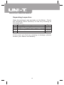
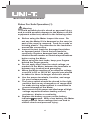
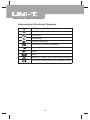
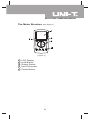
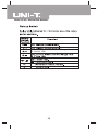
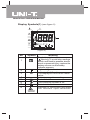
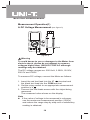
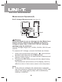
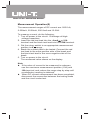
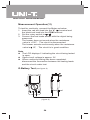
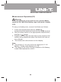
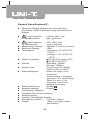
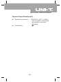
Model UT90A: OPERATING MANUAL
Table of Contents
Title
Page
Overview
Unpacking Inspection
Safety Information
Rules For Safe Operation
International Electrical Symbols
The Meter Structure
Rotary Switch
Functional Buttons
Display Symbols
Measurement Operation
A. DC Voltage Measurement
B. AC Voltage Measurement
C. DC Current Measurement
D. AC Current Measurement
E. Resistance Measurement
F. Testing Diodes & Continuity
G. Battery Test
General Specifications
Accuracy Specifications
A. DC Voltage
B. AC Voltage
C. DC Current
D. AC Current
E. Resistance
F.
Diodes & Continuity Test
Maintenance
A. General Service
B. Replacing the Fuses
C. Replacing the Battery
1
3
4
5
6
8
9
10
11
12
14
14
16
17
19
20
22
24
26
28
28
28
29
29
30
30
31
31
31
32
Model UT90A: OPERATING MANUAL
2
Model UT90A: OPERATING MANUAL
Overview
This Operating Manual covers information on safety and
cautions. Please read the relevant information carefully
and observe all the Warnings and Notes strictly.
Warning
To avoid electric shock or personal injury, read the
"Safety Information" and "Rules for Safe Operation"
carefully before using the Meter.
The Model UT90A (hereafter referred to as “the Meter”)
is a 1999 counts 3 1/2 digits multimeter with stabilized
functions, safe design, and reliable performance.
In addition to the conventional measuring function, such
as DC/AC voltage, DC/AC current, resistance, diode and
continuity, it is also a highly applied digital electrical tester
of good performance with battery test, large LCD full
icons display, full overload protection and streamline
outlook.
3
Model UT90A: OPERATING MANUAL
Unpacking Inspection
Open the package case and take out the Meter. Check
the following items carefully to see any missing or
damaged part:
Item
1
2
3
4
Description
English Operating Manual
Test Lead
9V Battery (NEDA 1604, 6F22 or 006P)
Holster
Qty
1 piece
1 pair
1 piece
1 piece
In the event you find any missing or damage, please
contact your dealer immediately.
4
Model UT90A: OPERATING MANUAL
Safety Information
This Meter complies with standards IEC61010: in pollution
degree 2, overvoltage category (CAT. II 1000V, CAT. III
600V) and double insulation.
CAT.II: Local level, appliance, PORTABLE EQUIPMENT
etc., with smaller transient overvoltages than CAT. III
CAT.III: Distribution level, fixed installation, with smaller
transient overvoltages than CAT. IV
Use the Meter only as specified in this operating manual,
otherwise the protection provided by the Meter may be
impaired.
In this manual, a Warning identifies conditions and
actions that pose hazards to the user, or may damage
the Meter or the equipment under test.
A Note identifies the information that user should pay
attention on.
International electrical symbols used on the Meter and
in this Operating Manual are explained on page 8.
5
Model UT90A: OPERATING MANUAL
Rules For Safe Operation (1)
Warning
To avoid possible electric shock or personal injury,
and to avoid possible damage to the Meter or to the
equipment under test, adhere to the following rules:
l
l
l
l
l
l
l
l
l
Before using the Meter inspect the case. Do
not use the Meter if it is damaged or the case (or
part of the case) is removed. Look for cracks or
missing plastic. Pay attention to the insulation
around the connectors.
Inspect the test leads for damaged insulation
or exposed metal. Check the test leads for
continuity. Replace damaged test leads with
identical model number or electrical specifications
before using the Meter.
When using the test leads, keep your fingers
behind the finger guards.
Do not apply more than the rated voltage, as
marked on the Meter, between the terminals or
between any terminal and grounding.
When the Meter working at an effective voltage
over 60V in DC or 30V in AC, special care should
be taken for there is danger of electric shock.
Use the proper terminals, function, and range
for your measurements.
The rotary switch should be placed in the right
position and no any changeover of range shall
be made during measurement is conducted to
prevent damage of the Meter.
Disconnect circuit power and discharge all highvoltage capacitors before testing current,
resistance, diodes or continuity.
Replace the battery as soon as the battery
indicator appears. With a low battery, the Meter
might produce false readings that can lead to
electric shock and personal injury.
6
Model UT90A: OPERATING MANUAL
Rules For Safe Operation (2)
l
l
l
l
l
l
l
When servicing the Meter, use only the same
model number or identical electrical specifications
replacement parts.
The internal circuit of the Meter shall not be
altered at will to avoid damage of the Meter and
any accident.
Soft cloth and mild detergent should be used
to clean the surface of the Meter when servicing.
No abrasive and solvent should be used to
prevent the surface of the Meter from corrosion,
damage and accident.
Turn off the Meter when it is not in use and
take out the battery when not using for a long
time.
Constantly check the battery as it may leak when
it has been using for some time, replace the
battery as soon as leaking appears. A leaking
battery will damage the Meter.
Do not use or store the Meter in an environment
of high temperature, humidity, explosive,
inflammable and strong magnetic field. The
performance of the Meter may deteriorate after
dampened.
The Meter is suitable for indoor use.
7
Model UT90A: OPERATING MANUAL
International Electrical Symbols
AC (Alternating Current).
DC (Direct Current).
AC or DC.
Grounding.
Double Insulated.
Deficiency of Built-In Battery.
Continuity Test.
Diode.
Fuse.
Warning. Refer to the Operating Manual.
Conforms to Standards of European Union.
8
Model UT90A: OPERATING MANUAL
The Meter Structure (see figure 1)
( figure 1)
1
2
3
4
5
LCD Display.
Hold Button.
Rotary Switch.
Input Terminals.
Power Button.
9
Model UT90A: OPERATING MANUAL
AC Current Measurement Range from
0.1µA to 10A
µ
10
Model UT90A: OPERATING MANUAL
Functional Buttons
Below table indicated for information about the functional
button operations.
AC
voltage measurement.
Turn the power on and off.
HOLD
l
l
l
Press HOLD once to enter hold mode.
Press HOLD again to exit hold mode
and the present value is shown.
In Hold mode, is displayed
11
Model UT90A: OPERATING MANUAL
Display Symbols(1) (see figure 2)
mVVΩk ΩMΩ
AC
µ AmAA
( figure 2)
No.
Symbol
1
2
3
AC
4
5
6
7
8
Connect
Terminal
Meaning
The battery is low.
Warning: To avoid false readings,
which could lead to possible electric
shock or personal injury, replace the
battery as soon as the battery
indicator appears.
High voltage indicator
Indicator for AC voltage or current.
The displayed value is the mean
value.
Indicates negative reading.
Test of diode.
The continuity buzzer is on.
Date hold is active.
Indicator of connecting test leads
into different input terminals.
12
Model UT90A: OPERATING MANUAL
Display Symbols(2) (see figure 2)
No.
9
Symbol
Meaning
Ω: Ohm. The unit of resistance.
Ω,kΩ,MΩ kΩ: kilohm.1 x 103 or 1000 ohms.
MΩ: Megaohm. 1 x 10⁶ or
1,000,000 ohms.
mV, V
V: Volts. The unit of voltage.
mV: Millivolt. 1 x 10⁻³ or 0.001 volts.
A: Amperes (amps). The unit of
current.
µA, mA, A mA: Milliamp. 1 x 10⁻³ or 0.001
amperes.
µA: Microamp. 1x 10⁻⁶ or 0.000001
amperes.
13
Model UT90A: OPERATING MANUAL
Measurement Operation(1)
A.DC Voltage Measurement (see figure 3)
red
black
( figure 3)
Warning
To avoid harms to you or damages to the Meter from
electric shock, please do not attempt to measure
voltages higher than 1000V DC/750V AC although
readings may be obtained.
The DC voltage ranges are: 200.0mV, 2.000V, 20.00V,
200.0V and 1000V.
To measure DC voltage, connect the Meter as follows:
1. Insert the red test lead into the VΩ
terminal and
the black test lead into the COM terminal.
2. Set the rotary switch to an appropriate measurement
position in V .
3. Connect the test leads across with the object being
measured.
The measured value shows on the display.
Note
l If the value of voltage to be measured is unknown,
use the maximum measurement position (1000V)
and reduce the range step by step until a satisfactory
reading is obtained.
14
Model UT90A: OPERATING MANUAL
Measurement Operation(2)
l
The LCD displays “1” indicating the existing selected
range is overloaded, it is required to select a higher
range in order to obtain a correct reading.
l In each range, the Meter has an input impedance
of approx. 10MΩ. This loading effect can cause
measurement errors in high impedance circuits. If
the circuit impedance is less than or equal to 10kΩ,
the error is negligible (0.1% or less).
l When DC voltage measurement has been completed,
disconnect the connection between the testing leads
and the circuit under test.
15
Model UT90A: OPERATING MANUAL
Measurement Operation(3)
B.AC Voltage Measurement (see figure 3)
red
black
( figure 3)
Warning
To avoid harms to you or damages to the Meter from
electric shock, please do not attempt to measure
voltages higher than 1000V DC/750V AC although
readings may be obtained.
The AC voltage ranges are: 2.000V, 20.00V, 200.0V and
750.0V.
To measure AC Voltage, connect the Meter as follows:
1. Insert the red test lead into the VΩ
terminal and
the black test lead into the COM terminal.
2. Set the rotary switch to an appropriate measurement
position in V range.
3. Connect the test leads across with the object being
measured.
The measured value shows on the display, which is
effective value of sine wave (mean value response).
Note
l If the value of voltage to be measured is unknown,
use the maximum measurement position (750V) and
reduce the range step by step until a satisfactory
reading is obtained.
16
Model UT90A: OPERATING MANUAL
Measurement Operation(4)
l
The LCD displays “1” indicating the existing selected
range is overloaded, it is required to select a higher
range in order to obtain a correct reading.
l In each range, the Meter has an input impedance of
approx. 10MΩ. This loading effect can cause
measurement errors in high impedance circuits. If the
circuit impedance is less than or equal to 10kΩ, the
error is negligible (0.1% or less).
l When AC voltage measurement has been completed,
disconnect the connection between the testing leads
and the circuit under test.
C.DC Current Measurement (see figure 4)
black
red
( figure 4)
Warning
Never attempt an in-circuit current measurement
where the open circuit voltage between terminals
and ground is greater than 60V DC or 30V rms.
If the fuse burns out during measurement, the Meter
may be damaged or the operator himself may be hurt.
Use proper terminals, function, and range for the
measurement. When the testing leads are connected
to the current terminals, do not parallel them across
any circuit.
17
Model UT90A: OPERATING MANUAL
Measurement Operation(5)
The measurement ranges of DC current are: 200.0µA,
2.000mA, 20.00mA, 200.0mA and 10.00A.
To measure current, do the following:
1. Turn off power to the circuit. Discharge all highvoltage capacitors.
2. Insert the red test lead into the µAmA or 10A
terminal and the black test lead into the COM terminal.
3. Set the rotary switch to an appropriate measurement
position in A range.
4. Break the current path to be tested. Connect the red
test lead to the more positive side of the break and
the black test lead to the more negative side of the
break.
5. Turn on power to the circuit.
The measured value shows on the display.
Note
l If the value of current to be measured is unknown,
use the maximum measurement position (10A) and
10A terminal, and reduce the range step by step until
a satisfactory reading is obtained.
l When DC current measurement has been completed,
disconnect the connection between the testing leads
and the circuit under test.
18
Model UT90A: OPERATING MANUAL
Measurement Operation(6)
D. AC Current Measurement (see figure 4)
black
red
( figure 4)
Warning
Never attempt an in-circuit current measurement
where the voltage between terminals and ground is
greater than 60V.
If the fuse burns out during measurement, the Meter
may be damaged or the operator himself may be hurt.
Use proper terminals, function, and range for the
measurement. When the testing leads are connected
to the current terminals, do not parallel them across
any circuit.
The measurement ranges of AC current are: 200.0µA,
2.000mA, 20.00mA, 200.0mA and 10.00A.
To measure current, do the following:
1. Turn off power to the circuit. Discharge all highvoltage capacitors.
2. Insert the red test lead into the µAmA
or 10A
terminal and the black test lead into the COM terminal.
3. Set the rotary switch to an appropriate measurement
position in A range.
19
Model UT90A: OPERATING MANUAL
Measurement Operation(7)
E. Measuring Resistance (see figure 5)
red
black
( figure 5)
Warning
To avoid damages to the Meter or to the devices
under test, disconnect circuit power and discharge
all the high-voltage capacitors before measuring
resistance.
20
Model UT90A: OPERATING MANUAL
Measurement Operation(8)
The resistance ranges are: 200.0 , 2.000k , 20.00k ,
200.0k , 2.000M and 20.00M .
To measure resistance, connect the Meter as follows:
1. Insert the red test lead into the V
terminal and
the black test lead into the COM terminal.
2. Set the rotary switch to an appropriate measurement
position in range.
3. Connect the test leads across with the object being
measured.
The measured value shows on the display.
Note
l The test leads can add 0.1 to 0.2 of error to the
resistance measurement. To obtain precision readings
in low-resistance, that is the range of 200 , shortcircuit the input terminals beforehand and record the
reading obtained (called this reading as X). (X) is
the additional resistance from the test lead.
Then use the equation:
measured resistance value (Y) – (X) = precision
readings of resistance.
l When the resistance reading 0.5 in the short-circuit
condition, please check for loose test leads or other
reasons.
l For high resistance (>1M ), it is normal taking
several seconds to obtain a stable reading, and it is
better to choose shorter test lead.
l When there is no input, for example in open circuit
condition, the Meter displays “1”.
l When resistance measurement has been completed,
disconnect the connection between the testing leads
and the circuit under test.
21
Model UT90A: OPERATING MANUAL
Measurement Operation(9)
F.Testing Diodes & Continuity
Warning
To avoid possible damage to the Meter and to the
device under test, disconnect circuit power and
discharge all high-voltage capacitors before testing
diodes and continuity.
Testing Diodes (see figure 6)
red
black
( figure 6)
Use the diode test to check diodes, transistors, and other
semiconductor devices. The diode test sends a current
through the semiconductor junction, then measures the
voltage drop across the junction. A good silicon junction
drops between 0.5V and 0.8V.
To test a diode out of a circuit, connect the Meter as follows:
1. Insert the red test lead into the VΩ
terminal and
the black test lead into the COM terminal.
2. Set the rotary switch to
.
3. For forward voltage drop readings on any semiconductor
component, place the red test lead on the component’s
anode and place the black test lead on the component’s
cathode.
The measured value shows on the display.
22
Model UT90A: OPERATING MANUAL
Measurement Operation(10)
Note
l
l
l
l
l
l
In a circuit, a good diode should still produce a forward
voltage drop reading of 0.5V to 0.8V; however, the
reverse voltage drop reading can vary depending
on the resistance of other pathways between the
probe tips.
Connect the test leads to the proper terminals as
said above to avoid error display.
The open-circuit voltage is around 3V when testing
diode.
The LCD will display 1 indicating open-circuit for
wrong connection.
The unit of diode is Volt (V), displaying the positiveconnection voltage-drop value.
When diode testing has been completed, disconnect
the connection between the testing leads and the
circuit under test.
Testing Continuity (see figure 7)
red
( figure 7)
23
black
Model UT90A: OPERATING MANUAL
Measurement Operation(11)
To test for continuity, connect the Meter as below:
1. Insert the red test lead into the VΩ
terminal and
the black test lead into the COM terminal.
2. Set the rotary switch to
.
3. Connect the test leads across with the object being
measured.
The buzzer does not sound when the resistance
value is >100Ω. The circuit is disconnected.
The buzzer sounds continuously when the resistance
value is 10Ω. The circuit is in good condition.
Note
l The LCD displays 1 indicating the circuit being tested
is open.
l Open-circuit voltage is approx. 3V.
l When continuity testing has been completed,
disconnect the connection between the testing leads
and the circuit under test.
G.Battery Test (see figure 8)
black red
( figure 8)
24
Model UT90A: OPERATING MANUAL
Measurement Operation(12)
Warning
To avoid damages to the built-In fuse and the Meter,
measure the specified battery type and power supply
only.
To carry out battery test, connect the Meter as follows:
1. Insert the red test lead into the µAmA
.
terminal and the black test lead into the COM terminal.
2. Set the rotary switch to an appropriate measurement
position in
range.
3. Parallel connect the red test lead on the anode of the
battery being tested and place the black test lead on
the cathode.
4. The measured value shows on the display.
Note
l The range of 1.5V only fit for the measure of 1.5V
Battery. Inside load resistance is 38Ω.
l The range of 9V only fit for the measure of 9V Battery.
Inside load resistance is 450Ω.
25
Model UT90A: OPERATING MANUAL
General Specifications(1)
l
Maximum Voltage between any terminals and
grounding: Refer to different range input protection
voltage.
l
Fuse Protection
of µA mA terminal
: 315mA, 250V, fast
type, 5x20mm
l
l
l
l
Fuse Protection
of 10A terminal
Measurement Speed
Maximum Display
Temperature
l
Relative Humidity
l
Altitude
l
Battery Type
l
Electro-Magnetic
l
l
l
l
l
l
l
l
: 10A, 250V, fast
type, 5x20mm
: Updates 2-3 times /second.
: 1999.
o
o
o
: Operating: 0 C~40 C(32 F
o
~104 F).
o
o
o
Storage: -10 C~50 C(14 F
o
~122 F).
o
o
: 75% @ 0 Cto below 30 C;
o
o
50% @ 30 Cto 40 C.
: Operating : 2000m.
Storage: 10000m.
: One piece of 9V (NEDA
1604 or 6F22 or 006P).
: When it is under 1V/m
frequency:
total accuracy = assigned
accuracy + 5% of the range.
When it is over 1V/m
frequency: there is no
assigned accuracy.
: Display
.
: Display
.
Battery Deficiency
Negative reading
Overloading: Display 1.
Equipped with full icons display.
Manual ranging.
Polarity: Automatically display.
Dimensions (HxWxL) : 179 x 88 x 39mm.
Weight
: 380g. (including holster
and battery)
26
Model UT90A: OPERATING MANUAL
General Specifications(2)
l
Safety/Compliances
l
Certification
: IEC61010: CAT. II 1000V,
CAT. III 600V overvoltage
and double insulation
standard.
:
27
Model UT90A: OPERATING MANUAL
Accuracy Specification(1)
Accuracy: (a% reading + b digits),guarantee for 1 year.
o
o
Operating temperature:18 C~28 C.
Relative humidity:<75%RH.
o
Temperature coefficient: 0.1 x (specified accuracy) / 1 C.
A. DC Voltage
Range Resolution
200mV
2V
20V
200V
1000V
0.1mV
1mV
10mV
100mV
1V
Accuracy
Overload
Protection
230VAC
(0.5%+2)
1000V DC
or 750V AC
rms.
continuous.
(0.8%+3)
Remark: Input impedance: 10MΩ
B. AC Voltage
Range Resolution
2V
20V
200V
750V
1mV
10mV
100mV
1V
Accuracy
(0.8%+5)
(1.0%+5)
Overload
Protection
1000V DC
or 750V AC
rms.
continuous.
Remarks:
l Input impedance: 10MΩ .
l Frequency response: 40Hz~400Hz.
l Display effective value of sine wave (mean value
response).
28
Model UT90A: OPERATING MANUAL
Accuracy Specification(2)
C. DC Current
Range Resolution
Accuracy
Overload
Protection
200µA
2mA
20mA
200mA
0.1µA
1µA
10µA
0.1mA
(0.8%+2)
Fuse 315mA,
250V, fast type,
5x20mm
10A
10mA
(1.2%+5)
Fuse 10A,
250V, fast type,
5x20mm
Remarks:
l At 10A Range:
For continuous measurement 10 seconds and
interval time between 2 measurement greater than
15 minutes.
D. AC Current
Range Resolution
Accuracy
Overload
Protection
200µA
2mA
20mA
200mA
0.1µA
1µA
10µA
0.1mA
(1.0%+5)
Fuse 315mA,
250V, fast type,
5x20mm
10A
10mA
(2.0%+5)
Fuse 10A,
250V, fast type,
5x20mm
Remarks:
l Frequency response: 40Hz – 400Hz.
l At 10A Range:
For continuous measurement 10 seconds and
interval time between 2 measurement greater than
15 minutes.
l Displays effective value of sine wave (mean value
response).
29
Model UT90A: OPERATING MANUAL
Accuracy Specification(3)
E. Resistance
200Ω
0.1Ω
2kΩ
20kΩ
200kΩ
2MΩ
20MΩ
1Ω
10Ω
100Ω
1kΩ
10kΩ
Overload
Protection
Accuracy
Range Resolution
(0.8%+3) +
short-circuit the
input terminals
(0.8%+3)
230V rms
(1.2%+5)
F. Diodes & Continuity Test
Range
Resolution
Overload Protection
1mV
230V rms
1Ω
Remarks:
l At Range:
Open circuit voltage approximate 3V.
l At Range:
Open circuit voltage approximate 3V.
The buzzer does not sound when the resistance
value is >100Ω. The circuit is disconnected.
The buzzer sounds continuously when the resistance
value is 10Ω. The circuit is in good condition.
30
Model UT90A: OPERATING MANUAL
Maintenance(1)
This section provides basic maintenance information
including battery and fuse replacement instruction.
Warning
Do not attempt to repair or service your Meter unless
you are qualified to do so and have the relevant
calibration, performance test, and service information.
To avoid electrical shock or damage to the Meter, do
not get water inside the case.
A. General Service
l
Periodically wipe the case with a damp cloth and
mild detergent. Do not use abrasives or solvents.
l To clean the terminals with cotton bar with detergent,
as dirt or moisture in the terminals can affect readings.
l Turn the Meter off when it is not in use and take out
the battery when not using for a long time.
l Do not store the Meter in a place of humidity, high
temperature, explosive, inflammable and strong
magnetic field.
B.Replacing the Fuses (see figure 9)
Holster
Screw
( figure 9)
31
Model UT90A: OPERATING MANUAL
Maintenance(2)
Warning
To avoid electrical shock or arc blast, or personal
injury or damage to the Meter, use specified fuses
ONLY in accordance with the following procedure.
To replace the Meter’s fuse:
1. Turn the Meter off and remove all connections from
the terminals.
2. Remove the holster from the Meter.
3. Remove the 3 screws from the case bottom, and
separate the case top from the case bottom.
4. Remove the fuse by gently prying one end loose,
then take out the fuse from its bracket.
5. Install ONLY replacement fuses with the identical
type and specification as follows and make sure the
fuse is fixed firmly in the bracket.
Fuse 1: 10A, 250V, fast type, 5x20 mm.
Fuse 2: 315mA, 250V, fast type, 5x20 mm.
6. Rejoin the case bottom and case top, and reinstall
the 3 screws and holster.
Replacement of the fuses is seldom required. Burning
of a fuse always results from improper operation.
C.Replacing the Battery (see figure 9)
Warning
To avoid false readings, which could lead to possible
electric shock or personal injury, replace the battery
as soon as the battery indicator
appears.
To replace the Meter’s battery:
1. Turn the Meter power off and remove all connections
from the terminals.
2. Take the Meter out from the holster.
32
Model UT90A: OPERATING MANUAL
3. Remove the 3 screws from the case bottom, and
separate the case top from the case bottom.
4. Remove the battery from the battery connector.
5. Replace with a new 9V battery (NEDA1604, 6F22 or
006P).
6. Rejoin the case bottom and case top, and reinstall
the 3 screws and the holster.
** END **
This operating manual is subject to change without notice.
33
Model UT90A: OPERATING MANUAL
34
Model UT90A: OPERATING MANUAL
35
Model UT90A: OPERATING MANUAL
Copyright 2001 Uni-Trend International Limited.
All rights reserved.
Manufacturer: UNI-TREND TECHNOLOGY(DONG GUAN)LIMITED
Address: Dong Fang Da Dao, Bei Shan Dong Fang Industrial
Development District, Hu Men Town, Dong Guan City,
Guang Dong Province, China
Headquarters: Uni-Trend International Limited
Address: Rm901, 9/F, Nanyang Plaza 57 Hung To Road
Kwun Tong Kowloon, Hong Kong
Tel: (852) 2950 9168
Fax: (852) 2950 9303
Email: [email protected]
http://www.uni-trend.com
36