1
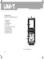
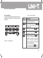
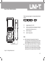
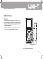
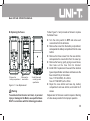
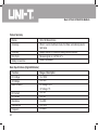
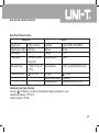
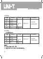
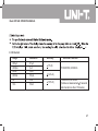
Model UT81A/B OPERATING MANUAL Model UT81A/B: OPERATING MANUAL Chapter Title 1 Before You Start Overview Unpacking Inspection Safety Information Rules For Safe Operation International Electrical Symbols Using The Testing Tool Reading the screen The Meter Structure Functional Buttons Making Measurements A. Scope Mode i. Setting up the Sleep Mode, Contrast, Beep ii. ACV, DCV, Hz, ACV and DCA Range iii. Trigger function iv. Waveform data save and recall B. Digital Multimeter Mode i. Measuring Voltages ii. Measuring Currents iii. Measuring Resistance iv. Testing Diodes v. Testing for Continuity vi. Measuring Frequency / Duty Cycle 2 3 Table of Contents Page 6 6 7 8 8 10 11 11 12 13 15 15 15 17 19 19 20 20 22 27 29 31 33 1 Model UT81A/B: OPERATING MANUAL Chapter 4 5 6 2 Title vii. Measuring Capacitance Using Software Maintenance The Test Tool A. General Service B. Replacing the Fuses C. Replacing the Battery Specifications Safety and Compliances Physical Specifications General Specifications (Digital Multimeter) General Specifications (Scope) Feature Summary Basic Specifications (Digital Multimeter) Basic Specifications (Scope) Detailed Accuracy Specifications A. DC Voltage B. AC Voltage C. DC Current D. AC Current E. Resistance F. Diode Test G. Continuity Test Table of Contents Page 35 37 38 38 39 40 41 41 42 43 43 44 44 45 45 46 46 47 48 49 49 50 Model UT81A/B: OPERATING MANUAL Chapter Title H. Frequency and Duty Cycle % I. Capacitance Table of Contents Page 50 51 3 Model UT81A/B: OPERATING MANUAL 4 Table Title 1-1 1-2 2-1 2-2 Unpacking Inspection International Electrical Symbols Reading the Screen Functional Buttons List of Tables Page 7 10 11 13 Model UT81A/B: OPERATING MANUAL Figure Title 2-1 2-2 3-1 3-2 3-3 3-4 3-5 3-6 3-7 3-8 3-9 3-10 5-1 5-2 Meter Structure Functional Buttons Waveform Display Voltages Measurement µA Range Measurement mA Range Measurement 10A Range Measurement Resistance Measurement Diode Test Continuity Test Frequency / Duty Cycle Measurement Capacitance Measurement Fuse Replacement Battery Replacement List of Tables Page 12 13 17 21 23 24 25 27 29 31 33 35 39 40 5 Model UT81A/B: OPERATING MANUAL Chapter 1 Before You Start Overview This Operating Manual covers information on safety and cautions. Please read the relevant information carefully and observe all the Warnings and Notes strictly. Warning To avoid electric shock or personal injury, read the “Safety Information” and “Rules for Safe Operation” carefully before using the Meter. Scope Digital Multimeter UT81A/B (hereafter referred to as “the Meter”) is a 3999 counts and 3 3/4 digits adopting digital control techique with both waveform and multimeter all in one. Scope mode is a complete intelligent measurement system including signal input, sampling, data process, auto search and waveform save and recall. It has 6 bandwidth UT81A:2MHz,UT81B:8MHz, real-time sample rate 40MS/s with peak rate sampling process can catch up pulse industrial signal. It can measure AC/DC engine, transducer, circuit, control, UPS and industrial equipments. It is an ideal tools in professional repairing industries. Digital Multimeter mode can measure AC voltage and current, DC voltage and current, Resistance, Capacitance, Frequency, Duty Cycle, Diodes and Continuity. Model UT81A/B: OPERATING MANUAL Unpacking Inspection Open the package case and take out the Meter. Check the items shown on Table 1-1 carefully to see any missing or damaged part: Table 1-1. Unpacking Inspection Item Description Qty 1 English Operating Manual 1 piece 2 USB interface cable 1 piece 3 CD-ROM (Installation Guide & Computer Interface Software) 1 piece 4 Test Lead 1 pair 5 Alligator Clip 1 piece 6 Power Adaptor 1 piece 7 1.5V Batteries (R6) 4 pieces 8 Carrying bag 1 piece 9 Scope Probe (available at extra cost) 1 piece 10 BNC probe (available at extra cost) In the event you find any missing or damage, please contact your dealer immediately. 7 Model UT81A/B: OPERATING MANUAL Safety Information This Meter complies with the standards IEC61010 safety measurement requirement: in pollution degree 2, overvoltage category (CAT. II 1000V, CAT.III 600V) and double insulation. International electrical symbols used on the Meter and in this Operating Manual are explained on page 10. Rules For Safe Operation Warning CAT.II: Local level, appliance, PORTABLE EQUIPMENT etc., with smaller transient overvoltages than CAT. III CAT. III: Distribution level, fixed installation, with smaller transient overvoltage than CAT. IV Use the Meter only as specified in this operating manual, otherwise the protection provided by the Meter may be impaired. In this manual, a Warning identifies conditions and actions that may pose hazards to the user, or may damage the Meter or the equipment under test. A Note identifies the information that user should pay attention to. 8 To avoid possible electric shock or personal injury, and to avoid possible damage to the Meter or to the equipment under test, adhere to the following rules: Before using the Meter inspect the case. Do not use the Meter if it is damaged or the case (or part of the case) is removed. Look for cracks or missing plastic. Pay attention to the insulation around the connectors. Inspect the test leads for damaged insulation or exposed metal. Check the test leads for continuity. Replace damaged test leads with identical model number or electrical specifications before using the Meter. Do not apply more than the 1000V rms between any terminal and grounding to avoid electric Model UT81A/B: OPERATING MANUAL shock or damages to the Meter. l The rotary switch should be placed in the right position and no any changeover of range shall be made during measurement is conducted to prevent damage of the Meter. l When the Meter working at an effective voltage over 60V in DC or 42V rms in AC, special care should be taken for there is danger of electric shock. l Use the proper terminals, function, and range for your measurements. l Do not use or store the Meter in an environment of high temperature, humidity, explosive, inflammable and strong magnetic field. The performance of the Meter may deteriorate after dampened. l When using the test leads, keep your fingers behind the finger guards. l Disconnect circuit power and discharge all highvoltage capacitors before testing resistance, continuity, diodes. l Before measuring current, check the Meter’s fuses and turn off power to the circuit before connecting the Meter to the circuit. l Replace the battery as soon as the battery indicator appears. With a low battery, the Meter might produce false readings that can lead to electric shock and personal injury. l When servicing the Meter, use only the same model number or identical electrical specifications replacement parts. l The internal circuit of the Meter shall not be altered at will to avoid damage of the Meter and any accident. l Soft cloth and mild detergent should be used to clean the surface of the Meter when servicing. No abrasive and solvent should be used to prevent the surface of the Meter from corrosion, damage and accident. l The Meter is suitable for indoor use. l Turn the Meter off when it is not in us e and take out the battery when not using for a long time. l Constantly check the battery as it may leak when it has been using for some time, replace the battery as soon as leaking appears. A leaking battery will damage the Meter. 9 Model UT81A/B: OPERATING MANUAL l Under the influence of Radiated Radio-Frequency Electromagnetic Field phenomenon, the captioned model have a 20% measurement error, it will be back to normal when the interference is removed. International Electrical Symbols Symbols used on the Meter and in this manual are explained in Table1-2. Table 1-2. International Electrical Symbols AC or DC DC Measurement AC Measurement Continuity Test Diode Grounding Double Insulated Warning. Refer to the Operating Manual Deficiency of Built-In Battery Conforms to Standards of European Union 10 Model UT81A/B: OPERATING MANUAL Chapter 2 Using the Testing Tool Reading the Screen The screen displays the menu that provides the following choices available: Table 2-1. Reading the Screen Display Contrast Auto Off BK Light BEEP ENTER MOVE MOVE RANG Description The degree of contrast Sleep mode time Display backlight Beeper on and off Confirm Increase Decrease Waveform moves up Waveform moves down Increase a range Table 2-1. Reading the Screen Display RANG BASE BASE BASE > BASE < TRIG TRIG SLOP AUTO NORM SHOT Description Decrease a range Increase a time base Decrease a time base Waveform moves right Waveform moves left Trigger moves up Trigger moves down Trigger slope adjustment Auto trigger mode Normal trigger mode Single trigger mode 11 Model UT81A/B: OPERATING MANUAL The Meter Structure The Figure 2-1 shows the Meter structure. 1. 2. 3. 4. 5. 6. 7. 8. 9. USB Terminals LCD Display Functional Buttons Rotary Switch Power adaptor Input Terminals 10A Input Terminal mAµA Input Terminals COM Input Terminal Other Input Terminals Figure 2-1. Meter Structure 12 Model UT81A/B: OPERATING MANUAL Functional Buttons The buttons activate features that augment the function selected with the rotary switch. The buttons are shown in Table 2-2. Table 2-2. Functional Buttons Buttons F1, F2, F3 and F4 Range Time Trig Auto Figure 2-2. Functional Buttons Description Software functional buttons, details please refer to the below. Under scope mode, Press Range button to switch between DC and AC measurement Under scope mode, press Time button to set the X-axis of time base. Under scope mode, press Trig button to change the trigger mode. In multimeter mode: Press Auto button to enter autoranging mode when measuring resistance, voltage and current. This button is invalid when measuring capacitance, diode, continuity buzzer and capacitance. In scope mode: Press Auto button to set the amplitude and time base to auto. 13 Model UT81A/B: OPERATING MANUAL Table 2-2. Functional Buttons Description To switch between waveform display (scope mode) and digital reading (multimeter mode). This button is only valid when under voltage, frequency, currents mode. Press Set button to set the auto power Set off, backlight, contrast and beep Save/Call Under scope mode, press Save/Cal to store and recall data. Press Hold button to enter or exit hold Hold mode. Buttons Mode 14 Model UT81A/B: OPERATING MANUAL Chapter 3 Making Measurement Introduction Chapter 3 explains how to make measurements. You could turn the Meter off by turning to OFF position or set up the sleep mode from 1-30 minutes. Please must ensure the Meter is not under sleep mode if you turn the Meter on but without display. To avoid false readings, which could lead to possible electric shock or personal injury, replace the battery as soon as the battery indicator “ ” appears. Based on the working environment to set up sleep mode, contrast, beep Press Set button to set the auto power off, display backlight, contrast and beep Auto off Bk Light Contrast Beep F1 F2 F3 F4 F1: Set auto power off time Auto off 15 ENTER F1 F2 F3 F4 The time level is from OFF, 1 to 30 minutes. Press F4 to confirm, save and return. Press functional button to exit and the setting remains unchanged. 15 Model UT81A/B: OPERATING MANUAL F2: Set the Display Backlight BK Light 15 ENTER F1 F2 F3 F4 The brightness level from 0 to 31. Press F4 to confirm, save and return. Press functional buttons to exit, the setting is kept, but will not save. The setting will be lost after power off. F3: Set the LCD contrast Contrast 15 ENTER F1 F2 F3 F4 The contrast level from 0 to 31. Press F4 to confirm, save and return. Press functional buttons to exit, the setting is kept, but will not save. The setting will be lost after power off. 16 F4: Set the beeps features, it can only be used under resistance, diode and continuity measurement. Beep ON OFF ENTER F1 F2 F3 F4 F2 : F3 : F4 : to turn the beep on to turn the beep off to confirm , save and return Press functional buttons to exit, the setting is kept, but will not save. The setting will be lost after power off. Model UT81A/B: OPERATING MANUAL Turn the rotary switch to ACV, DCV, Hz, ACA or DCA range, the Meter displays digital reading (Multimeter mode). Press Mode to switch to waveform display (scope mode) as below Figure 4. When entering scope mode, time base is auto trace, the amplitude is manual set, you may need to re-set them. You could set the trigger level as well if it is needed. Details of measurement operation of ACV, DC, Hz, ACA or DCA can be seen from B. Digital Multimeter Mode: Press Range to switch between DC and AC measurement. When the frequency and amplitude of a waveform is unknown, press Auto : When the amplitude is set to auto, the amplitude indicator will be shown white text in black background. When the amplitude is set to manual, the amplitude indicator will be shown black text in white background. When the time base is set to auto, the time base indicator will be shown white text in black background. When the time base is set to manual trace, the time base indicator will be shown black text in white background. When the time base is between 20ms - 100ns, it is possible to set the auto. When the time base is between 50ms - 5s, the auto feature will be in valid. Figure 3-1. Waveform Display 17 Model UT81A/B: OPERATING MANUAL Y-axis adjustment: Press Range button under scope mode, the corresponding functional button: Move Move Rang Rang F1 F2 F3 F4 F1: F2: F3: F4: F1: F2: F3: F4: The auto set feature will be off when changing the measurement mode. move up the waveform move down the waveform go up range go down a range The auto set feature will be off when changing the measurement mode Press Time button under scope mode, the corresponding functional button: Base Base Base < Base > F1 F2 F3 F4 18 increase the number of periods decrease the number of periods. trigger point move left trigger point right move Model UT81A/B: OPERATING MANUAL Press Trig button under scope mode, the corresponding function buttons: Trig Trig Auto/Norm/Shot Slop Rrise/Fall F1 F2 F3 F4 F1: F2: F3: F4: move the trigger level up move the trigger level down select the trigger mode: auto, normal or single slope adjustment: rise or fall iv. Waveform data save and recall Press Save/Call button under scope mode, the corresponding functional buttons: Save/Call 1 Enter F1 F2 F3 F4 F1: save or recall F2 and F3: select location (location from 0-9, total 10 location) F4: confirm When saving the data, it will overwrite the current data in the location no matter that location has data or not. If you recall the location has no data, the meter will appear error message, you need to press HOLD button to continue measurement, If you recall the location has data, it will save the current setting and display the data, the LCD top left shows REV to indicate recalling mode is on. Press HOLD button to return to working mode and continue measurement. You could continue recalling under recall mode or save the data. Recall mode can be used under any scope mode. For example, it is possible to recall the waveform or data saved from voltage or frequency mode when the meter is under current measurement mode. Recall mode can be worked under any waveform mode. For example: the Meter is at current mode but recalling the waveform or data which are saved under voltage or frequency mode. The Meter must 19 Model UT81A/B: OPERATING MANUAL be returned to working mode to carry out measurement. In order to have more accurate waveform, user can buy an optional BNC probe and scope probe to decrease signal attenuates. The scope probe directly connect to the BNC probe. When measuring voltage and frequency signal, connect the BNC black probe to the COM input terminal and the red probe to the voltage terminal. When measuring current signal, connect BNC black probe to the COM terminal and the red probe to mA terminal. Don’t connect the BNC probe to the 10A terminal. 20 B. Digital Multimeter Mode Warning To avoid harms to you or damages to the Meter from electric shock, please do not attempt to measure voltages higher than DC 1000V, AC 750V, although readings may be obtained. To measure voltages, set up the Meter as Figure 32 and do the following: 1. Insert the red test lead into the V terminal and the black test lead into the COM terminal. 2. Set the rotary switch to V . 3. Connect test leads across with the object being measured. 4. The measured value shows on the display. 5. Press MODE button to toggle between Multimeter mode and Scope mode. 6. Press F1 to toggle between AC and DC voltage measurement. Model UT81A/B: OPERATING MANUAL When measuring voltage, the corresponding functional buttons AC / DC REL Rang Rang F1 F2 F3 F4 F1: F2: toggle between AC or DC relative mode (REL will be displayed at the right bottom of the LCD when it is on) select a range up select a range down F3: F4: Note: After changing the measurement mode, the autoranging will be off automatically and the AUTO will be disappeared at the bottom left of the LCD. When voltage measurement has been completed, disconnect the connection between the testing leads and the circuit under test and remove testing leads away from the input terminals of the Meter. Figure 3-2. Voltages Measurement 21 Model UT81A/B: OPERATING MANUAL Warning If the fuse burns out during measurement, the Meter may be damaged or the operator himself may be hurt. To avoid possible damage to the Meter or to the equipment under test, check the Meter’s fuses before measuring current. Use proper terminals, function, and range for the measurement. Never place the testing leads in parallel with any circuit or component when the leads are plugged into the current terminals. Turn off power to the circuit before test leads are connected in series to the return circuit to be tested. 22 Model UT81A/B: OPERATING MANUAL To measure ACµA or DCµA currents, set up the Meter as Figure 3-3 and proceed as follows: 1. Insert the red test lead into the µmA terminal and black test lead into the COM terminal. 2. Set the rotary switch to µA . 3. Connect the test lead in series with the return circuit to be tested. 4. The measured value shows on the display. 5. Press MODE button to toggle between Multimeter mode and Scope mode. 6. Press F1 to toggle between AC and DC current measurement. Figure 3-3. µA Range Measurement 23 Model UT81A/B: OPERATING MANUAL To measure ACmA or DcmA currents, set up the Meter as Figure 3-4 and proceed as follows: Figure 3-4. mA Range Measurement 24 1. Insert the red test lead into the µAmA terminal and black test lead into the COM terminal. 2. Set the rotary switch to mA . 3. Connect the test lead in series with the return circuit to be tested. 4. The measured value shows on the display. 5. Press MODE button to toggle between Multimeter mode and Scope mode. 6. Press F1 to toggle between AC and DC current measurement. Model UT81A/B: OPERATING MANUAL To measure AC 10A or DC 10A currents, set up the Meter as Figure 3-5 and proceed as follows: 1. Insert the red test lead into the 10A terminal and black test lead into the COM terminal. 2. Set the rotary switch to A . 3. Connect the test lead in series with the return circuit to be tested. 4. The measured value shows on the display. 5. Press MODE button to toggle between Multimeter mode and Scope mode. 6. Press F1 to toggle between AC and DC current measurement. Figure 3-5. 10A Range Measurement 25 Model UT81A/B: OPERATING MANUAL When measuring current, the corresponding functional buttons: AC / DC F1 F1: F2: F3: F4: 26 REL F2 Rang F3 Rang F4 toggle between AC or DC relative mode (REL will be displayed at the right bottom of the LCD when it is on) select a range up select a range down Note After changing the measurement mode, the autoranging will be off automatically and the AUTO will be disappeared at the bottom left of the LCD. If the value to be measured is unknown, use the maximum measurement position and reduce the range step by step until a satisfactory reading is obtained. When the measured current is 5A, continuous measurement is allowed. When the measured current is between 5A-10A, continuous measurement 10 seconds and interval more than 15 minutes. When current measurement has been completed, disconnect the connection between the testing leads and the circuit under test and remove testing leads away from the input terminals of the Meter. Model UT81A/B: OPERATING MANUAL Warning To avoid possible damages to the Meter or to the devices under test, disconnect circuit power and discharge all the high-voltage capacitors before measuring resistance. To measure resistance, set up the Meter as shown in Figure 3-6 and follow the following procedure: Figure 3-6. Resistance Measurement 27 Model UT81A/B: OPERATING MANUAL 1. Insert the red test lead into the Ω terminal and the black test lead into the COM terminal. 2. Set the rotary switch to Ω 3. Connect the test leads across with the object being measured. 4. The measured value shows on the display. When measuring resistance, the corresponding functional buttons: RES REL Rang Rang F1 F2 F3 F4 F1: F2: F3: F4: 28 toggle to diode mode relative mode select to a range up select to a range down Note When measuring low resistance, the test leads can add 0.1Ω to 0.2Ω of error to resistance measurement. To test the leads, touch the probe tips together and read the resistance of the leads. Take the reading obtained to subtract the resistance of the leads to get the final reading. For high-resistance measurement (>1MΩ) or low resistance measurement (<40Ω), it is normal taking several seconds to obtain a stable reading. The LCD displays “OL” indicating open-circuit without input. When resistance measurement has been completed, disconnect the connection between the testing leads and the circuit under test and remove testing leads away from the input terminals. Model UT81A/B: OPERATING MANUAL To test the diode out of a circuit, set up the Meter as Figure 3-7 and proceed as follows: Warning To avoid harms to you, please do not attempt to input voltages higher than 60V DC or 42V rms AC. To avoid damages to the Meter or to the devices under test, disconnect circuit power and discharge all the high-voltage capacitors before testing diodes. Use the diode test to check diodes, transistors, and other semiconductor devices. The diode test sends a current through the semicondutor junction, then measure the voltage drop across the junction. A good silicon junction drops between 0.5V and 0.8V Figure 3-7. Diode Test 29 Model UT81A/B: OPERATING MANUAL 1. Insert the red test lead into the Ω terminal and the black test lead into the COM terminal. 2. Set the rotary switch to Ω . 3. For forward voltage drop readings on any semiconductor component, place the red test lead on the component’s anode and place the black test lead on the component’s cathode. The red test lead polarity is “+” while the black test lead polarity is “— “. The measured value shows on the display. When measuring diode, the corresponding functional buttons: DIODE REL F1 F2 F1: toggle to continuity buzzer F2: relative mode 30 Note Connect the test leads to the proper terminals as said above to avoid error display. The LCD will display OL indicating either open circuit or wrong polarity connection. The unit of diode is volt (V), displaying the positiveconnection voltage-drop value. When diode testing has been completed, disconnect the connection between the testing leads and the circuit under test and remove the test leads away from the input terminals. Model UT81A/B: OPERATING MANUAL To test for continuity, set up the Meter as Figure 3-8 and do the following: Warning To avoid harms to you, please do not attempt to input voltage higher than 60V DC or 42V rms AC. To avoid possible damages to the Meter or to the devices under test, disconnect circuit power and discharge all the high-voltage capacitors before measuring continuity. Figure 3-8. Continuity Test 31 Model UT81A/B: OPERATING MANUAL 1. Insert the red test lead into the W terminal and the black test lead into the COM terminal. 2. Set the rotary switch to Ω . 3. Connect the test leads across with the object being tested. 4. The tested circuit overload resistance value shows on the display. 5. The beeper comes on continuously for open conditions, that is test resistance 10W. 6. The beeper does not sound when the test resistance is 100W When measuring continuity buzzer, the corresponding functional buttons: CONTINUITY REL F1 F2 F1: F2: 32 toggle to resistance measurement mode relative mode Note When continuity testing has been completed, disconnect the connection between the testing leads and the circuit under test and remove the test leads away from the input terminals. Model UT81A/B: OPERATING MANUAL Warning To avoid harms to you, please do not attempt to input voltage higher than 42V rms. To measure frequency and duty cycle, connect the Meter as Figure 3-9 and do the following: 1. Insert the red test lead into the Hz terminal and the black test lead into the COM terminal. 2. Set the rotary switch to Hz. 3. Connect the test leads across with the object being measured. 4. The measured value shows on the display. 5. Press MODE button to toggle between Multimeter mode and Scope mode. 6. Press F1 to toggle between frequency and duty cycle measurement. When measuring frequency and duty cycle, the corresponding functional buttons: Freq/Duty F1 F1: toggle between frequency and duty cycle Figure 3-9. Measuring Frequency / Duty Cycle 33 Model UT81A/B: OPERATING MANUAL Note The requirement of Input amplitude “a” is as follows: When 1MHz: 300 mV a 30Vrms; 1MHz: 600 mV a 5Vrms It is normal to have few seconds run time when switch from other functions to these functions. When Hz or duty cycle measurement has been completed, disconnect the connection between the testing leads and the circuit under test and remove the test leads away from the input terminals. 34 Model UT81A/B: OPERATING MANUAL To measure capacitance, set up the Meter as shown in Figure 3-10 and proceed as follows: Warning To ensure accuracy, the Meter inside is discharged against the tested capacitor To avoid damage to the Meter or to the equipment under test, disconnect circuit power and discharge all high-voltage capacitors before measuring capacitance. Figure 3-10. Measuring Capacitance 35 Model UT81A/B: OPERATING MANUAL 1. Insert the red test lead into theterminal and the black test lead into the COM terminal. 2. Set the rotary switch to measurement mode, the Meter may display a fixed reading which is a internal distributed capacitor value. For testing less than 40nF capacitor, the tested value must subtract the internal distributed capacitor value to maintain the accuracy. 3. To improve the accuracy, press F2 REL with the test leads open to subtract the residual capacitance of the Meter and the test leads. 4. It is recommended to use as short as test lead carrying out measurement to reduce the effect of internal distributed capacitor. 36 When measuring capacitance, the corresponding functional buttons: Capacity REL F1 F2 F2: relative mode Note Capacitors larger than 10 F take longer time. If the tested capacitor has polarity, connect the red test lead to positive side and black test lead to negative side. When capacitance measurement has been completed, disconnect the connection between the testing leads and the circuit under test and remove the test leads away from the input terminals of the Meter. Model UT81A/B: OPERATING MANUAL Chapter 4 Using Software When using the Software, please refer to the Installation Guide of the included CD-ROM. 37 Model UT81A/B: OPERATING MANUAL Chapter 5 Maintaining The Test Tool This chapter provides basic maintenance information including battery and fuse replacement instruction. Warning Do not attempt to repair or service your Meter unless you are qualified to do so and have the relevant calibration, performance test, and service information. A. General Service l Periodically wipe the case with a damp cloth and mild detergent. Do not use abrasives or solvents. l To clean the terminals with cotton bar with detergent, as dirt or moisture in the terminals can affect readings. l Turn the Meter to OFF when it is not in use. l Take out the battery when it is not using for a long time. l Do not use or store the Meter in a place of humidity, 38 high temperature, explosive, inflammable and strong magnetic field. Model UT81A/B: OPERATING MANUAL B. Replacing the Fuses 1.Remove the 2.Remove the battery compartment case bottom Follow Figure 5-1 and proceed as follows to replace the Meter’s fuse: 3.Install fuses with correct type and specification Figure 5-1. Fuse Replacement Warning To avoid electrical shock or arc blast, or personal injury or damage to the Meter, use specified fuses ONLY in accordance with the following procedure. l Turn the rotary switch to OFF and remove all connections from the terminals. l Remove the screw from the battery compartment, and separate the battery compartment from the case bottom. l Remove the three screws from the case bottom, and separate the case bottom from the case top. l Remove the fuse by gently prying one end loose, then take out the fuse from its bracket. l Install ONLY replacement fuses with the identical type and specification as follows and make sure the fuse is fixed firmly in the bracket. Fuse 1: F0.5AH/250V, ø5 x 20mm Fuse 2: F10AH/250V, ø5 x 20mm l Rejoin the case bottom and case top, battery compartment and case bottom, and install the 5 screws. Replacement of the fuses is seldom required. Burning of a fuse always results from improper operation. 39 Model UT81A/B: OPERATING MANUAL C. Replacing the Battery Warning To avoid false readings, which could lead to possible electric shock or personal injury, replace the battery as soon as the battery indicator “ ” appears. Make sure the test leads are disconnected from the circuit being tested before opening the case bottom. Follow Figure 5-2 and proceed as follows to replace the battery: Turn the rotary switch to OFF and remove all connections from the terminals. Remove the screw from the battery compartment, and separate the battery compartment from the case bottom. Replace with 4 pieces new 1.5V (R6P) batteries. Rejoin the case bottom and battery compartment, and reinstall the screw. Figure 5-2. Battery Replacement 40 Model UT81A/B: OPERATING MANUAL Chapter 6 Specifications Safety and Compliances Maximum Voltage between any Terminal and Grounding Certification Compliances Fused Protection for mA input terminal: Fused Protection for 10A input terminal: Refer to different range input protection voltage IEC 61010 CAT. II 1000V, CAT.III 600V overvoltage and double insulation standard F0.5AH/250V, ø5×20mm F10AH/250V, ø5×20mm 41 Model UT81A/B: OPERATING MANUAL Physical Specifications Display (LCD) Operating Temperature Storage Temperature Relative Humidity Altitude Battery Type Electromagnetic Compatibility Dimensions (H x W x L) Weight 42 Digital: 3999 counts on display ; updates 2-3 times / second. o o o o 0 C~40 C (32 F~104 F) o o o o -10 C~50 C (14 F~122 F) o o 75% @ 0 C~40 C; o o 0% @ -10 C~50 C. Operating: 2000m; Storage: 10000m. 1.5V (R6) x 4 Batteries or Power adaptor. Check carefully about the working voltage of power adaptor before use. l In a radio field of 1 V/m below: Overall Accuracy = Specified Accuracy + 5% of Range l In a radio field of 1 V/m above: No assigned accuracy is specified. 200 x 100 x 48mm. Approx. 498g (including battery) Model UT81A/B: OPERATING MANUAL General Specifications ( Digital Multimeter) Range Polarity Overloading Battery Deficiency When it is under Multimeter mode, you could select either auto or manual ranging. Auto, negative polarity displays “-“ Display OL Display General Specifications (Scope) Display Auto setting Overloading Memory USB Tilt Stand 160 x 160 Monochrome Auto set the Meter according to the tested signal size Display OL 10 screens and setups Optically isolated to ensure safety Allowing viewing at a convenient position and angle. 43 Model UT81A/B: OPERATING MANUAL Feature Summary Display Autorange Continuity Duty Cycle Battery Access Door 160 x 160 Monochrome When it is under multimeter mode, the Meter automatically selects best range Beeper sounds for resistance readings below threshold. Measure signal on or off time in %. Battery replaceable. Basic Specifications (Digital Multimeter) Function DC Voltage AC Voltage Basic Accuracy DC Current AC Current Resistance Capacitance Frequency 44 Ranges / Description 0 to 1000V 0 to 750V DC Voltage: 0.8% AC Voltage: 1% 0 to 10A 0 to 10A 0 to 40MΩ 0 to 100µF 0~10MHz Model UT81A/B: OPERATING MANUAL Basic Specifications (Scope) Horizontal Sampling rate Sampling rate / Scale Updating rate Trigger types Timebase Range Timebase accuracy 40M per second 20 pixels >5 Free Run / Normal / Single Shot 100ns/div~5 sec /div (1-2-5) (0.1% + 1pix) Vertical Bandwidth Channel Coupling Voltage resolution UT81A:2MHz,UT81B:8MHz Single DC 8 Bits Input Impedance 10MΩ (excluding Multimeter part) Accuracy Maximum input voltage Voltage Sensitivity (5%+1pix) 1000Vp-p 20mV/div~500V/div (1-2-5) Detailed Accuracy Specifications Accuracy: ([% of reading] + [number of least significant digits]), guarantee for 1 year. o o Operating temperature: 18 C~28 C Relative humidity: <75%RH 45 Model UT81A/B: OPERATING MANUAL A. DC Voltage Range 400mV 4V 40V 400V 1000V Resolution 100µV 1mV 10mV 100mV 1V Accuracy (0.8%+8) Overload Protection 1000V DC or AC Input Impedance Around 10MΩ (excluding waveform) (0.1%+8) B. AC Voltage Range 4V 40V 400V 750V 46 Resolution 1mV 10mV 100mV 1V Accuracy (1%+15) (1.2%+15) Overload Protection 1000V DC or AC Input Impedance Around 10MΩ (excluding waveform) Model UT81A/B: OPERATING MANUAL C. DC Current Range Resolution 400µA 4000µA 40mA 400mA 4A 10A 0.1µA 1µA 10µA 100µA 1mA 10mA Accuracy (1%+8) Overload Protection F0.5AH/250V, ø5×20mm (1.2%+8) (1.5%+8) F10AH/250V, ø5×20mm. (Continuous measurement 10 seconds and interval more than 15 minutes.) 47 Model UT81A/B: OPERATING MANUAL D. AC Current 48 Range Resolution 400µA 4000µA 40mA 400mA 4A 10A 0.1µA 1 µA 10µA 100µA 1mA 10mA Accuracy (1.5%+8) Overload Protection F0.5AH/250V, ø5×20mm (2%+8) (2.5%+5) F10AH/250V, ø5×20mm (Continuous measurement 10 seconds and interval more than 15 minutes.) Model UT81A/B: OPERATING MANUAL E. Resistance Range Resolution 400Ω 4kΩ 40kΩ 400kΩ 4MΩ 40MΩ 0.1Ω 1Ω 10Ω 100Ω 1kΩ 10kΩ Accuracy Overload Protection (1.2%+5) (1%+5) 250VDC or AC rms (1.2%+5) (1.5%+5) F. Diode Test Range Resolution 1mV Overload Protection 250V DC or AC Remarks A good silicon junction drops between 0.5V and 0.8V. 49 Model UT81A/B: OPERATING MANUAL G. Continuity Test Test Range Resolution 0.1Ω Overload Protection 250V DC or AC Remarks The buzzer sounds when the test resistance is 10Ω. The buzzer does not sound when the test resistance is 100Ω. H. Frequency and Duty Cycle % 50 Range Resolution Accuracy Overload Protection 10Hz~10MHz 0.1%~99.9% 0.001Hz 0.1% (0.1%+3) Reading for reference only 250V DC or AC rms Model UT81A/B: OPERATING MANUAL I. Capacitance Range Resolution Accuracy 40nF 400nF 4µF 40µF 100µF 10pF 100pF 1nF 10nF 100nF Under REL mode: (3%+10) (3%+8) Overload Protection 250V DC or AC rms (4%+8) 51 Model UT81A/B: OPERATING MANUAL ** END ** This operating manual is subject to change without notice. 52 Model UT81A/B: OPERATING MANUAL Copyright 2006 Uni-Trend Group Limited. All rights reserved. Manufacturer: Uni-Trend Technology (Dongguan) Limited Dong Fang Da Dao Bei Shan Dong Fang Industrial Development District Hu Men Town, Dongguan City Guang Dong Province China Postal Code: 523 925 Headquarters: Uni-Trend Group Limited Rm901, 9/F, Nanyang Plaza 57 Hung To Road Kwun Tong Kowloon, Hong Kong Tel: (852) 2950 9168 Fax: (852) 2950 9303 Email:[email protected] http://www.uni-trend.com 53