1
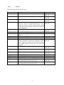
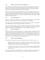
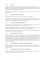
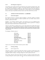
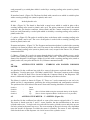
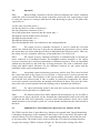
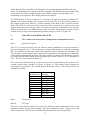
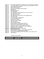
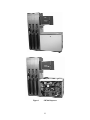
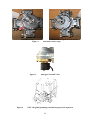
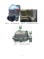
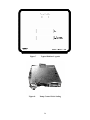
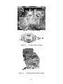
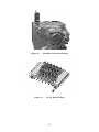
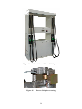
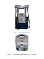
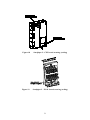
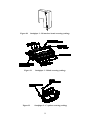
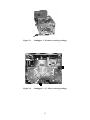
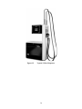
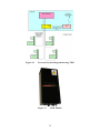
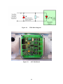
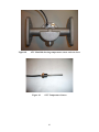
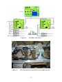
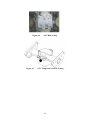
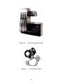
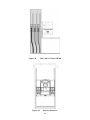
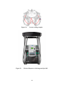
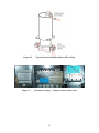
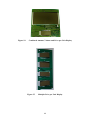
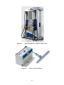
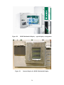
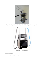
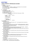
(2650/76)
III(5)a
Certificate
Pursuant to section 12 of the
Weights and Measures Act 1985
Certification No 2650/76
Valid Until 1 July 2016
In accordance with the provisions of section 12 of the Weights and Measures Act 1985, the
Secretary of State for Business, Innovation & Skills hereby certifies as suitable for use for
trade a pattern of a liquid flowmeter as described in the descriptive annex to this Certificate,
and having the following characteristics:Gilbarco SK700 series dispensers as described in the Descriptive
Annex
As described in the associated certificates: 2650/55
DISPENSER:
POINT OF SALE
SYSTEMS
As described in the associated certificates: 2650/55 and in the
Descriptive Annex
VAPOUR RECOVERY
SYSTEM:
Under the provisions of section 12(6) of the said Act, the validity of this certificate is limited
as shown above.
Note: This certificate relates to the suitability of the equipment for use for trade only in
respect of its metrological characteristics. It does not constitute or imply any guarantee as to
the safety of the equipment in use for trade or otherwise.
Submitted by:
Signatory:
for
Reference No: T1117/0008
Date: 22 November 2012
Gilbarco Veeder-Root
Crompton Close
Basildon
Essex, SS14 3BA
United Kingdom
P R Dixon
Chief Executive
National Measurement Office
Department for Business, Innovation & Skills
Stanton Avenue
Teddington
Middlesex TW11 0JZ
United Kingdom
Descriptive Annex
1
INTRODUCTION
This pattern is for an electrically driven liquid fuel dispensing system termed SK700. The
SK700 series models (Figure 1) are multi–product and have up to six pumping units for 6 grades
of fuel. Only one nozzle per side can be used at any one time: the withdrawal of a nozzle to start
a refuelling operation prevents the delivery of any other product on the same side.
The transaction data for each side is shown on the display of the control head. The dispenser
can indicate up to 999.99 Litres, giving an indication every 0.01 Litres. The price-to-pay
indication indicates up to £999.99 in intervals of £0.01. The unit price increments every 0.1
pence per Litre up to a maximum of 999.9 pence per Litre.
The dispenser consists of up to six hydraulic grades, containing electrically driven monobloc
pumps, hoses, optional dry break coupling, automatic nozzles, meters and pulsers connected to
the electronic unit and Display Assembly. The dispenser can be operated in a self service mode
via the 2 wire communication loop, or IFSF (LON) communications - and can also be operated
in a standalone mode. Flow from either nozzle can be at standard rate (45 Litres/minute
nominal) or at high flow rate (85 Litres/minute nominal), or at an Ultra high flow rate (120
Litres/minute).
Nozzles are mounted on one or both sides of the dispenser, providing a maximum of 6 discreet
products. Both sides of the dispenser can be used at the same time. The Hose Cabinet can be
either a standard hanging hoses version or can incorporate a hose retraction system. When the
hose retraction system is used, the height of the Hose Cabinet is reduced.
The meter has no mechanical calibration device. The dispenser is calibrated electronically
within the electronic unit.
This pattern is suitable for liquids other than water of low viscosity (<20mPa.s) except
liquefied gases.
2
CONSTRUCTION
2.1
Mechanical
The frame construction is Non-Modular. There are four basic sections to the build - the
hydraulic section, the electronics module, the Display module and the Hose Cabinet section.
The housing of the hydraulics is constructed from a welded and bolted metal frame, the side,
end and top sections being clad with metal or fibreglass panels, secured by key type locks.
The electronics module is located within the top of the hydraulic housing and sits above an
IP67 barrier effectively separating the two sections. The Display module is clad with metal
or fibreglass panels with transparent display windows. The Hose Cabinets are constructed
from a welded and bolted frame with stainless front sheathing holding the nozzle boot
assemblies.
2
2.2
Hydraulics
This consists of the monobloc pumping units, meters, solenoid valves and interconnecting
pipework. Flow rate options are 40 L/Min, 80 L/Min and 120 L/Min. The option for 120 L/Min
would use 2 meters in parallel.
2.2.1
Combined pump and air separator - Monobloc
This is a Blackmer Monobloc unit which is to an OIML approved design, and incorporates a
screw in gas detector unit which electrically connects to the electronics Intrinsically Safe
Barrier board and stops the flow of fuel if excess air or gas is detected.
2.2.2
Meter
There are two types of meter used in this dispenser. The ‘C+ Meter’ and the ‘Ecometer’
The C+ meter is a positive displacement type manufactured by Gilbarco. It converts the flow of
fuel into a rotary motion. The rotary motion is transmitted mechanically to the pulser. The meter
may be fitted with either 4 bolts or 8 bolts. Both meters with 4 and 8 bolt fixings are shown in
figure 2.
The Ecometer is a twin screw meter manufactured by Gilbarco, which converts the flow of fuel
into a rotary motion which is transmitted to the attached pulser.
In both cases, for calibration purposes, an electronic calibration unit is used as described in
Section 3.2
2.2.3
Solenoid Valves
This is a double stemmed digital proportional valve. This valve can be used to vary the flow rate
from full flow to zero flow in small increments. It is suitable for both non-preset and preset
applications. It can also be used for prepay transactions, provided the kiosk equipment has been
suitably approved for such.
Having an alternative valve that is analogue (proportional), with the functionality remaining the
same. A picture of the proportional valve is shown in figure 3. An alternative valve driver board
(part number M02044) is required to drive the proportional valve.
3
2.2.4
Nozzles
The following nozzles may be used:
Manufacturer
Elaflex
Elaflex
Elaflex
Elaflex
Elaflex
Elaflex
Elaflex
Elaflex
Elaflex
Husky
Goodyear
Goodyear
Goodyear
Goodyear
OPW
OPW
OPW
OPW
Model/Description
ZVA 4.4R for use with unleaded petrol
Type
Automatic
Shut-off
ZVA 4.4 for use with leaded petrol and diesel
Automatic
Shut-off
ZVA 25.41 high flow nozzle for diesel
Automatic
Shut-off
ZVA Slimline Drip Stop nozzle Minimum Automatic
Delivery 5 litres. (A legend indicating a 5 litre Shut-off
minimum delivery will be marked on the spout
of the nozzle, this marking overrides that marked
on the dispenser).
ZVA Slimline 2
Automatic
Shut-off
ZVA X204 GRV3G for use with unleaded petrol Vapour Recovery
ZVA X204 GRV3R-BL for use with leaded Vapour Recovery
petrol
ZVA X204M GRVP
Vapour Recovery
ZVA Slimline 2 GR
Vapour Recovery
Type ‘X’ series, single and double poppet Automatic
designs. Optional accessories including swivel Shut-off
joints, sight glass option, and alternative spouts
and splash guards which may be fitted as
required.
GTR 50 for flowrates up to 50 litres /minute
Automatic
Shut-off
GTR 80 for flowrates up to 80 litres /minute
Automatic
Shut-off
GTR 120 for flowrates up to 120 litres /minute
Automatic
Shut-off
GTR 50 VR
Vapour Recovery
11 VAIE-0035 for use with unleaded petrol
Vapour Recovery
11 VAIE-0037 for use with leaded petrol
Vapour Recovery
12 EN (may be fitted with different sizes of Automatic
spout depending on the product type)
Shut-off
12 EN V (may be fitted with different sizes of Vapour Recovery
spout depending on the product type)
4
2.2.5
Hoses
The following hoses may be used:
Manufacturer
Model
Elaflex, Germany
Elaflex, Germany
Elaflex, Germany
Elaflex, Germany
Good Year, USA
Good Year, USA
Good Year, USA
Conti – Slimline 25 Low temperature
Conti – Slimline 21 Low temperature
Conti – Slimline 16 Low temperature
Conti – Slimline 21 MPD
EN1360 TYPE 3 25mm 16 BAR M 1Q00 0310
EN1360 TYPE 3 16mm 16 BAR M 1Q99 0749
¾”Hardwall Petrol Hose
Maximum length
(Metres)
6
10
13
7
15
15
15
2.2.6
Alternative Hydraulics
2.2.6.1
GPU 140 global pumping unit and integrated air separator
Having a Gilbarco Veeder-Root GPU 140 global pumping unit and integrated air separator. It
is suitable for use in flow rates up to 140 litres per minute from a single nozzle, or 70 litres
per minute for two nozzles.
The GPU 140 cover and control valve is sealed to the pumping unit as shown in figure 4. The
seal wire passes through two bolt heads in the control valve body, then routed through two
bolt heads in the pumping top cover casting. The two ends of the wire are then passed
through the lead seal, pulled taut, and sealed.
2.2.7.2
Global pumping unit (figure 5a).
As described in the certificate, but having optionally fitted an alternative pumping unit:- the
Gilbarco Veeder-Root Global pumping unit type GPU-90. This pumping unit is suitable for
use at flow rates of up to 90 litres per minute.
The pumping unit cover and control valve is sealed to the pumping unit as shown in figure
5b. The seal wire passes through pre-drilled holes in two bolt-heads in the control valve body
and is then routed through pre-drilled holes in two bolt-heads in the pumping top cover
casting. The two ends of the wire are then passed through the lead seal, pulled taut, and
sealed.
2.3
Electrical
Mains power to the dispenser is single-phase 230 V, 50 Hz, or 3 phase 400 V, 50 Hz.
The motors that drive the pumping unit are single phase or 3 phase rated up to 1.5 kW.
2.4
Electronics
The Electronics are known as Sandpiper. The main electronics are housed within the
Electronics Module. The Display Module contains the Pump Door nodes (transaction
displays), The Price Per Unit displays, the optional Electromechanical Totalisers, Power
supplies, optional Battery Back up board, and Keypads.
5
The optional Battery Back up board supplies power to the electronics for a period of 15
minutes after mains power fail. This allows the dispenser to communicate to the kiosk
equipment during power fail, and send it any transaction data stored in the dispenser. It is
mainly intended for use with certain types of Kiosk equipment operating over IFSF
communications and working in Buffered transaction mode.
2.4.1
Electronics Module
This is located above the Hydraulic section in a separate enclosure. It contains some or all of the
following electronic components –
Pump Control Node board
Valve board
STP board
IS Barrier board
IFSF Interface board
Vapour Recovery Controller
Ecal board
Pulsers (C+ Meter) (see 2.4.3)
M00056A001 or M01922A001
M00059A002 or M02044*
M00047A001
M01267A002
M00074G001
140489603 (MCVR125)
M01270A001
M00786B001
*for analogue solenoid valve control
2.4.2
Display Module
This contains the following electronic components –
Pump Door Node
PPU Board
Electromechanical Tote Board
Power Control Module
Battery Back up Board
Keypad
2.4.3
M00062A001 or M01785A001
M00065A001
M00077A001
M02262A001
140 774 056
****
Pulse Generators
The Ecometer Pulser is part of the Ecometer design and is integrated into an explosion proof
housing.
The C+ meter pulser is not explosion proof and is located in the electronics module. The pulser
shaft is sealed as it passes through the electronic module lower barrier and is coupled to the
meter shaft.
Alternatively the SK700 pulser manufactured by Gilbarco GmbH & Co. KG may be used. The
sealing arrangement is shown in figure 6
2.5
Displays and legends (Figure 7)
A typical dialface is shown in Figure 7. This shows the legends and the display positions.
Notes: The minimum delivery specified is either 2 or 5 Litres, but this may optionally be higher
dependant on the maximum flow rate of the dispenser.
A dispenser may also have additional Price per unit displays for each nozzle.
6
LEGEND
£
Litres
Pence Per Litre
Minimum Delivery 2 Litres
CHARACTER HEIGHT (mm)
16
12
5
5
2.6
Standard Sealing
2.6.1
Pump Control Node Sealing (Figure 8)
The Board is fitted with a metal cover which is sealed in place with sealing wire and a lead seal.
The calibration switch fitted to the metal cover is also sealed with sealing wire and a lead seal.
Alternatively a plastic seal wire, rather than metallic may be used.
2.6.2
C+ Meter (Figure 9)
A sealing wire passes through holes in each of the cylinder covers, the seal wire is then drawn
tight and sealed with a lead seal. The meter is also sealed to the frame of the dispenser via the
upper cylinder cover hole using a sealing wire and lead seal.
2.6.3
C+ Meter Pulser Sealing (Figure 10)
A seal wire passes through the heads of bolts at the top of the pulser, through small holes in the
pulser top and is sealed using a lead seal.
2.6.4
Ecometer & Pulser Sealing (Figure 11)
A seal wire passes through 2 of the pulser fixing bolts and is sealed with a lead seal. The meter
is also sealed to the frame of the dispenser using a sealing wire and lead seal.
2.6.5
Monobloc Gas Detector Sealing (Figure 12)
A seal wire passes through a hole in the lower corner of the Gas Detector unit and then through a
hole in the Monobloc unit and is then sealed with a lead seal. Alternatively, taking the seal wire
on through a bolt at the front of the Monobloc, and through a bolt at the rear of the Monobloc
in order to prevent access to the inside of the air separator.
2.6.6
ECAL Board Sealing (Figure 13)
The Board is fitted with a metal cover which is sealed in place with sealing wire and a lead seal.
The calibration switches are also individually sealed with sealing wire and a lead seal.
Alternatively the unused switch seal plates may all be tied together with one seal wire and one
lead seal. Alternatively a plastic seal wire, rather than metallic may be used.
7
3
DISPENSER OPERATION
3.1
Operating Sequence
At the start of the transaction, the dispenser displays the previous sale. When the dispenser is
in the self-service mode, the customer selects the grade of fuel required. As a result of the
purchasers activity, the operator through the kiosk control unit (if applicable), may authorise the
use of the dispenser. After a display test (all ‘8’s, all ‘blanks’, then all ’0’s. The unit price is
displayed and the customer then delivers the required amount of fuel and replaces the nozzle in
its stowage.
Where both sides of the dispenser are available for use, each side operates independently and
separate transactions may occur simultaneously.
3.2
Electronic Calibration (ECAL)
To calibrate the dispenser a calibration coefficient is obtained by delivering a quantity of fuel
into a reference volume measure. The error from the reference fuel delivered is entered into the
calculator and a calibration coefficient is obtained and is stored automatically into non volatile
memory. The calibration coefficient can be displayed for future reference using the appropriate
keypad entries. Full details of the calibration procedure may be found in the Gilbarco technical
documentation.
3.3
Interlocks and Security Features
Interlocks are provided as follows :(a)
The delivery is stopped when the pump detects an error condition.
(b)
In the event of a mains supply failure, displays at the dispenser are maintained
for at least 15 minutes.
(c)
A period of 5 seconds must elapse before a delivery of fuel can be authorised
following the replacement of the nozzle in the previous transaction.
(d)
Price per unit volume cannot be changed after any operation has been made on
the dispenser to initiate a transaction and before the expiry of the 5 second guard
time (as in (c)).
(e)
Any operations on the keypad inside the computing head are inhibited when a
transaction is in progress on either side of the pump.
(f)
A transaction cannot be started with a price per unit volume setting of zero.
4
AUTHORISED ALTERNATIVES
4.1
Alternative Enclosure Arrangements
4.1.1
There may be any configuration of hydraulic units up to maximum of twelve
hoses. There may be an unequal number of hoses.
8
4.1.2
Arranged to dispense from one side of the unit only, in which case without:
meters, pulsers, solenoid valves and associated pipework for the blank side. The dial mask
displays and associated electronic circuitry are replaced with a blanking plate.
4.1.3
Without electromechanical totes.
4.1.4
Having the fuel supplied to the dispenser unit by a Submersible Turbine Pump
(STP), in which case motors, pumping units & air separators are not fitted. A check valve is
fitted at each of the meters in the dispensing unit and a solenoid valve is fitted. The storage tank
from which the STP delivers the product shall be equipped with a level detection device. The
level detection device is connected to the system to prevent the pumping unit from operating
when a low level is detected.
4.1.5
Preset operation in the kiosk, whereby the amount of volume of fuel or the price
to pay for the fuel is preset or prepaid in the kiosk. In this case the dispenser must ensure the
transaction stops on the exact amount of fuel preset or prepaid.
4.1.6
With or without a hose retraction system. With the hose retraction system, the
overall height is 1850 mm. Without the hose retraction system, the overall height is increased to
2165 mm.
4.1.7
of fuel.
Having either one price per unit display, or price per unit displays for each grade
4.1.8
Multiplex version of dispenser. One Ecometer is shared by up to 3 specific
grades in this configuration. This uses a Valve Block with integrated steering valves and
directly connected Ecometer, and steering valves for hose selection.
The grades specified for sharing must be fuels that will not suffer cross-contamination, for
example, various petrol grades.
Dispensers thus modified shall indicate that minimum delivery is 5 litres.
4.1.9
With any nozzle with high flow-rate capability configured as dual speed
(standard flow or high flow) selectable via a push-button switch adjacent to the nozzle. The
nozzle shall return automatically to standard flow upon completion of high flow delivery.
4.1.10
With high flow nozzles on both sides of the dispenser driven by an ultra high
flow monobloc (120 L/min).
4.2
Alternative Dispenser Styles
4.2.1
LPG module
Having an LPG dispensing module, either in the form of a separate dispenser, or in addition
to other modules, such as being integrated into a multiproduct dispenser. The LPG module
contains parts suitable for use with LPG. Transaction data for the LPG section may connect
to approved site control equipment.
Note: The LPG hydraulics are not prescribed under the Liquid Fuel and Lubricants
Regulations.
9
4.2.2
H Frame construction - Encore 510 (Figure 14)
As described in the Certificate, but having a new style enclosure designated the ‘Encore 510’.
This is an ‘H’ Frame style of dispenser, having a hose retractor unit separate from the main
hydraulics. The manager keypad and electromechanical totalisers are accessible via hinged
drop down doors situated on the front panel of the computer head
Sealing is similar to that of the standard with the exception of the pulser used with the C+
meter, the wire passes through the bolt which fixes the pulser to the pulser bracket, the wire
then passes through the bolt which fixes the pulser bracket to the meter. The ends are brought
together and both covered by a seal. The pulser is manufactured by Eltomatic and the sealing
method is illustrated in figure 15.
4.2.3
Encore 500G (Figure 16)
This is an ‘H’ Frame style of dispenser. An alternative Transaction Display board is included
(M07856), which has a single piece LCD glass with larger Price to Pay Digits.
The manager keypad and optional Electromechanical Totalisers are accessible via hinged drop
down lockable doors situated on the front panel of the Computer Head.
Note: The Computer Head is designed to be fitted with optional Card Reader components
(Display, Card Reader, PIN PAD, and printer). These do not form part of this approval, and the
Computer Head is fitted with blanking plates to cover the apertures for these devices.
4.2.4
Infoscreen (Figure 17)
Having an Info Screen terminal attached, this is a display terminal, providing picture and
sound for advertising, safety announcements, and travel information etc. The signal can be
supplied from disk, satellite broadcast, ethernet or any other suitable display source, all of
which are either mounted remotely from the dispenser, or located inside the Computer Head.
The dispenser may be configured with a screen on one, or both sides. The screen sizes can be
typically 5.7”, or can be up to a PC screen size of typically 17”.
4.2.5
End Accessed SK700 Dispenser
As described in the certificate, but having the Dispenser hoses in an ‘End Accessed’ style.
•
Single Hose Version (Figure 34). A single hose version can serve both sides of the
dispenser with the transaction being displayed on both sides of the Computer Head
simultaneously. This only requires one set of hydraulics.
•
Two hose version (Figure 35). A two hose version can dispense the same grade of fuel
to each side, or can dispense different Grades of fuel to each side, dependent on the
hydraulics fitted.
Flow rates can be either 40 LPM, 80LPM or 120 LPM also dependent on the hydraulic and
type of Pumping unit fitted. LPG hydraulics may be installed as described in section 4.2.1.
10
4.2.6
Adblue
Having an Adblue dispensing module, either in the form of a separate dispenser, or in
addition to other modules, such as being integrated into a multiproduct dispenser. The Adblue
module contains parts suitable for use with Adblue. Transaction data for the Adblue section
may connect to approved site control equipment.
Note: The Adblue hydraulics are not prescribed under the Liquid Fuel and Lubricants
Regulations.
4.2.7
Nordic Lane Dispenser (Figure 46)
As described in the certificate, but with Cosmetic changes to the packaging.
The Computer Head is slightly smaller than the standard SK700, and the optional PPU
displays are fitted vertically on the Computer Head Door. Several of the panels are now
curved, to give a more rounded look to the Dispenser aesthetics.
4.2.8
Taller Hose Cabinet SK700 (Figure 48)
As described in the certificate, but with an increased hose cabinet height which is
approximately 2400mm high which allows for a longer hose reach.
Any approved payment terminal under certificate 2650 may be fitted as an option, either
below the computer head as shown, or integrated into a larger computer head.
Any approved display types may be fitted. The ‘Price Per Unit’ displays may be fitted either
horizontally or vertically in the computer head.
4.2.9.
Horizon Dispenser (Figure 49)
This is an alternative ‘H’ frame style of dispenser. It may include the transaction display
(M07856) with larger digit displays as introduced with the Encore 500G dispenser. The
electronics enclosure is accessed via a large door, which is normally manufactured from
plastic. Painted steel versions are also permitted. This door also carries the nozzle boots. The
computer head is designed to be fitted with optional card reader components. These do not
form part of this approval, and the computer head is fitted with blanking plates to cover the
apertures for these devices.
4.2.10
Horizon Dispenser with integrated SPOT M3 (Figure 51)
Having the Horizon style dispenser frame as described in section 4.2.9, with the Spot M3
payment terminal as approved in Supplement Certificate Series S030 integrated into the
dispenser housing.
4.2.11
Horizon Dispenser with Hose Retraction (Figure 56)
Having the Horizon style dispenser as described in section 4.2.9 fitted with a hose retraction
system in the space above the electronics enclosure.
11
4.2.12
397G Dispenser (Figure 61)
As described in the certificate but having an alternative style enclosure designated 397G. This
is most commonly configured as a single or two product dispenser with nozzles mounted in
the columns and with displays allowing use of the nozzle on either side of the dispenser.
However, alternative arrangements exist which have a single display per side and dedicated
hoses per side (up to two products and four nozzles, max of one nozzle active per side).
4.3
ALTERNATIVE ELECTRONICS – SANDPIPER 2
4.3.1
General Description
The original electronics are replaced with the Sandpiper 2 electronics within the Computer
Head. The only electronic board now within the hydraulic unit is an ‘IS Hub’ which is used to
interface to pulsers and switches.
Sandpiper 2 also includes alternative pulsers. The Ecometer now uses an Eltomatic Pulser
ME01-04, and the C+ Meter uses a Gilbarco Veeder-Root IS Pulser type M03127. Sealing of
these pulsers and associated boards are described in section .
Cables are routed into the computer head via a new cable channel in the column and enter the
computer head via a ventilated channel underneath. Alternatively for the Encore 510, H-frame
construction, the cables are routed into the computer as before, via optional cable glands into the
side of the head. Minor changes have also been made to the Hydraulic Frame, the panels and the
Computer Head.
The Sandpiper 2 Boards consist of –
CPU board
Display board
ECAL board
Valve board
IS interface board
STP connector board
Single phase AC connector board
IS hub board
Battery back-up board
PPU board
IFSF board
M06104
M06113
M06110
M06031
M06202
M06107
M06214
M06205
M06208
M04329
M00074
Vapour recovery and vapour monitor boards may also be added.
4.3.2
Securing (Sealing)
4.3.2.1
In the computer head
CPU board: - (Figure 18) The board is fitted with a metal cover which is sealed in place with a
securing (sealing) wire (metal or plastic) and a seal. The calibration switch is protected by a
sealed plate which is sealed by a securing (sealing) wire (metal or plastic) and a seal.
ECAL board:- (Figure19) The board is fitted with a metal cover which is sealed in place with a
securing (sealing) wire (metal or plastic) and a seal. The meter calibration switches (16 total) are
12
each protected by a sealed plate which is sealed by a securing (sealing) wire (metal or plastic)
and a seal.
IS interface board:- (Figure 20) The board is fitted with a metal cover which is sealed in place
with a securing (sealing) wire (metal or plastic) and a seal.
4.3.2.2
In the hydraulic unit
IS hub:- (Figure 21) The board is fitted with a metal cover which is sealed in place with a
securing (sealing) wire (metal or plastic) and a seal. The pulser connectors (8 total), the switch
connector, the gas detector connector (where fitted) and the Comms connector (to computer
head) are each protected by a sealed plate which is sealed by a securing (sealing) wire (metal or
plastic) and a seal.
C+ pulser:- (Figure 22) The pulser is sealed in place to the frame with a securing (sealing) wire
(metal or plastic) and a seal. The cover of the pulser is sealed with a securing (sealing) wire
(metal or plastic) and a seal.
Ecometer and pulser:- (Figure 23) The Ecometer and associated pulser is sealed with a securing
(sealing) wire (metal or plastic) and a seal. The meter is also sealed to the frame of the dispenser
with a securing (sealing) wire (metal or plastic) and a seal, except for the Encore 510, H-frame
constructed model.
C+ Meter :- (Figure 24) A seal wire passes through holes in each of the cylinder covers, and is
sealed with a securing (sealing) wire (metal or plastic) and a seal. The meter is also sealed to the
frame of the dispenser via the upper cylinder cover hole with a securing (sealing) wire (metal or
plastic) and a seal, except for the Encore 510, H-frame constructed model.
4.4
METER
ALTERNATIVE METER – ENDRESS AND HAUSER CORIOLIS
As described in the certificate but with all or some of the meters replaced with an ‘Endress
and Hauser’ Coriolis meter type ‘LPGMass’ model DN15. The meter connects to the existing
‘IS Hub’, but the IS Hub is now located within the Computer Head of the Dispenser. The
meter is calibrated using the same electronic calibration procedure as before.
The Meter is sealed as shown in Figure 47. There are 2 seals connected to one seal wire,
which seal the 2 compartments, protecting the wiring terminals and configuration switches.
The position of the 4 Switches in the meter electronics housing should be set as below:
Switch a
Switch b
Switch c
Switch d
4.5
-
Down
Down
Up
Up
(Set to Volume Mode using the measured density of the liquid)
(Set to ‘Secure Operation Mode’ No Write access is possible)
ALTERNATIVE METER – V+ METER (Figure 50)
As described in the certificate but with all or some of the meters replaced with a V+ meter.
The meter is based upon the C and C+ meter families, but has modifications to the meter
cylinder end covers. A single seal wire seals all four meter cylinder covers and picks up two
seal wire points in the meter top cover. The exact routing of the seal wire may vary dependent
upon the model of dispenser in which the meter is installed. The meter is also separately
sealed to the frame of the dispenser via a hole in one of the cylinder covers.
13
4.6
ALTERNATIVE PULSER - SECURE INTELLIGENT PULSER (SIP)
The Secure Intelligent Pulser (SIP) mounts to the C+ or V meter and determines the quantity
of fuel dispensed by counting revolutions of the pulser input shaft. It stores the calibration
factor for its associated meter. A W&M-sealable switch is provided to control the changing
of the calibration data, and other basic configuration data. When the calibration switch is in
the normal sealed position, the pulser rejects any attempts to change the calibration data or
configuration data. When the switch is in the unsealed position, the pulser accepts correctly
formulated data from the CPU, and saves the data in non-volatile storage. Data encryption is
employed for the CPU to pulser communication. There is a non-volatile log of the most
recent change, which can be read by the CPU via the serial bus. To put the pulser into
calibration mode, a cap is removed and an LED, provided by GVR, is inserted into the top of
the calibration light tube/ programming port. Typical pulser is sealed as shown in Figure 52.
4.7
ALTERNATIVE SEALING METHOD – ECAL, IS HUB, ATC HUB
The pulser connections into the IS hub, and the temperature probe connections to the ATC
Hub, may alternatively be sealed using tamper evident sticker seals over the flat screw heads
used to secure the sealing plates. The ECAL board may use similar tamper evident sticker
seals to cover the small access holes to the ECAL switches. Examples are shown in Figure
53.
4.8
ALTERNATIVE DISPLAY BOARD
The amount, volume and price per unit may be combined into a single display board
(M10738) as shown in Figure 54. Price per unit displays for multiple fuel grades may
optionally be mounted onto a single board (M10735) as shown in Figure 55.
4.9
ADDITIONAL RS485 COMMUNICATIONS INTERFACE
CONVERTER (M06211)
An additional board may be used for conversion of the communications to RS485.
4.10
VOLUME ONLY DISPENSERS
Having the dispenser display masked such that only the volume is displayed.
4.11
ALTERNATIVE DISPLAY BOARDS
The amount, volume and price per unit may be indicated by a multimedia display (DIMP) as
shown in Figure 58. Display digits and text heights are in accordance with those defined
within this certificate. The metrologically relevant indication is permanently displayed, and is
segregated from non-metrological display content. In the event of a power fail, the primary
display is provided by an internal display as shown in Figure 59.
4.12
Alternative version of SIP Pulser
As described in the certificate but with the Secure Intelligent Pulser (SIP) in a smaller
housing and with an alternative calibration switch arrangement. The same light activated
calibration circuit is used; but the pulser is fitted with an internal light source. To put the
pulser into calibration mode, the seal wire is removed from a screw feature, and the screw is
rotated by 90 degrees to turn a mechanical light reflector. The pulser is typically sealed as
14
shown in Figure 60.
5
STAGE II VAPOUR RECOVERY
5.1
Construction
5.1.1
Components
The systems described typically consist of a mix of standard components described below:(a) Vapour recovery nozzle
(b) Vapour recovery hose
(c) Vapour pumps
See section 2.2.4
See section 2.2.5
ASF 8014 series
Durr MEX 0831 series
GR125
Alternatively any vapour recovery pumps
approved for use by TUV
(Note: These vapour pumps are typically
driven via either a single ended or double
ended AC motor)
(d) Proportional valve
Burkert 2832 series
Burkert 6022 series
(e) Fuel / vapour splitter adaptor
Elaflex ZAF series
(f)
Electronic control unit for Burkert 1094 series
vapour recovery system
Gilbarco VRC390/392 series
MCVR125
(g) Optional vapour meter
Gilbarco Veeder-Root GE1 meter.
Alternatively any Gilbarco Veeder-Root (or
Fafnir – Figure 57) meter for vapour
monitoring systems approved for use by TUV
(h) Electronic control unit
for vapour monitoring system
Gilbarco VMC390 /392 series
Alternatively any Gilbarco Veeder-Root (or
Fafnir) electronic control unit for vapour
monitoring systems approved for use by TUV
(i)
Gilbarco KAI392
Any kiosk equipment (eg: POS) with suitable
interface.
Alternatively any Gilbarco Veeder-Root
electronic control unit for vapour monitoring
systems approved for use by TUV
Kiosk alarm indicator
15
5.2
Operation
5.2.1
When fuelling commences, the fuel delivered displaces the vapour contained
within the vehicle fuel tank and the vapour is therefore forced out. The vapour pump is used
to collect the vapour as it emerges from the fuel tank. Referring to figure 25, the path of the
vapour flow is:Via the outer ring of the nozzle >
On into the inner core of the coaxial hose >
Into the splitter hose connector (ZAF) >
Out of the splitter hose connector into the vapour pipe >
Through the vapour monitor meter (if fitted) >
Through the proportional valve >
Through the vapour pump >
Then out through the shear valve and back to the underground tank.
5.2.2
The vapour recovery controller electronics is used to match the recovered
vapour rate with the fuel flow rate. It does this by adjusting the proportional valve to obtain
the vapour flow rate in line with the fuel flow as indicated by the fuel meter pulser. This way,
the vapour recovery volumetric efficiency is kept within the 95 to 105% level.
5.2.3
The vapour recovery controller electronics is calibrated using an external gas
meter connected to a handheld terminal. The handheld terminal interfaces to the vapour
recovery electronics by a serial port and initiates a calibration sequence. This is accomplished
without any fuel delivery and with only air being measured, also with a calibration factor
being used which makes allowance for the difference between air and vapour and the
particulars of the system components used.
5.2.4
An optional vapour monitoring system may also be used. This is used to check
the correct operation of the vapour recovery system. A vapour meter is used to measure the
vapour being recovered. This interfaces to the vapour monitor electronics, which compares
this with the fuel delivered and, if after a number of consecutive transactions the vapour
recovered is outside of specification, the monitor will indicate an alarm. This gives the owner
time to have the system repaired before the fuelling point is automatically shut down.
5.2.5
If a vapour monitoring system is not used, the recovery system will need to be
checked for correct operation on a regular basis.
5.2.6
The monitor alarm can be either indicated at the dispenser (eg: via an LED) or
a signal can be sent to the kiosk via the standard data communication line to the POS and
indicated at the POS itself. Optionally, a special ‘kiosk alarm indicator’ (KAI) can be fitted
which interfaces to the monitor system via a serial channel and indicates the alarm details in
the kiosk
5.3
Additional Two Wire Enhanced Vapour Recovery Monitor (TEM)
The TEM is used to allow Vapour Recovery Alarms to be returned from Vapour Monitoring
Controllers in dispensers, to the Automatic Tank Gauge (ATG) in the kiosk. This utilizes the
normal Gilbarco Two-Wire dispenser - kiosk communication channels, and avoids the need
to lay extra cables. The Alarms can be retrieved from the ATG using its existing interfaces.
A typical site using a TEM is as shown in Figure 36. This shows the existing Two-Wire
16
cables from the Site Controller to the dispensers now passing through the TEM inside the
Kiosk. No modification is required to the Site Controller. The TEM collects status data which
is already present in the existing messages. One TEM is capable of connecting to, and
monitoring, up to eight Two-Wire loops (only four are shown).
The TEM Module is shown in Figure 37, it consists of a metal box housing a standard CEmarked power-supply module and a printed circuit board. The Two-Wire cables connect to
the printed circuit board, which is a passive monitor of the data on the Two-Wire currentloops. The TEM is a read only device on the Two-Wire current loop, it cannot write to the
loop or change the data in any way. The Two-Wire current loops are unbroken even when the
TEM is powered down. The TEM connects to the Two-Wire current loops by means of optoisolators (one per loop) with a minimum breakdown voltage of 5300 V (Figure 38).
6
VOLUME CONVERSION DEVICES
6.1
TVC volume conversion device (Temperature compensation device)
6.1.1
System Description
The TVC is a conversion device for use with two meters, intended for correcting volumes of
fuel as if dispensed at 15°C. The temperature compensation function is added by connecting
the TVC unit between the pulse output of the dispenser pulser and dispenser calculator. The
TVC provides a pulse output stream corrected for temperature by monitoring the temperature
of the fluid passing through the meter. The pulse output is no longer a fixed number of pulses
per rotation of the meter output shaft, but adjusts the volume of fuel as if it is dispensed at
15°C. The TVC unit is shown in figure 26.
The conversion calculation for a certain density of fuel is determined by the selection of a
suitable density block (module) as shown in figure 28. The density block contains the
calculations as specified in the ASTM manual D1250-80, table 4. The density blocks are
identified as follows:
Module
identification
B1
B2
B3
B4
B5
B6
D1
D2
D3
D4
6.1.2
Construction
6.1.2.1
TVC unit
Density range
in kg/m3
720 - 730
730 - 740
740 - 750
750 - 760
760 - 770
770 - 780
810 - 820
820 - 830
830 - 840
850 - 860
The TVC circuit board is housed in a secure box which prevents unauthorised access to the
calibration button and the power supply, data link, temperature sensor, density block and
pulser connections. The box has a clear lid to allow inspection of the density block.
17
Optionally an LCD display (figure 27) may be installed which allows access to the following
data by pressing the scroll button:
•
•
•
•
•
•
6.1.2.2
Fixed Density
Temperature (Actual temperature from liquid)
Uncompensated volume 1(last delivery, 2 digits behind the comma)
Uncompensated volume 2(last delivery, 2 digits behind the comma)
When test button is pressed, display shows “bypass”
Display shows “ERROR” when the TVC is defective or errors occur
Temperature sensor
A temperature sensor manufactured by E. Meurs BV and designated LM335 is connected to
the TVC unit. The temperature sensor (figure 29) is installed in the fuel delivery pipe within
one metre from the flow meter; a typical installation is shown in figure 30.
6.1.2.3
Software
An infrared port in the TVC unit allows the reading of data and performing the calibration via
an infra red reader connected to a portable PC running the Windows based software ‘Fuel
Monitor’, produced by E. Meurs BV. A typical data display is shown in figure 33
The software version number is: V1.01 and can be accessed with the ‘Fuel Monitor’ software,
or by viewing the LCD screen in the TVC unit where fitted.
6.1.2.4
Indication of measurement result
A legend shall be affixed adjacent to the volume indication clearly indicating that the volume
dispensed is corrected to 15 °C.
6.1.3
Adjustments
Adjustments to the calibration and temperature compensation of the TVC unit may be made
using a PC having an infra red link and running ‘Fuel Monitor’ software or using the scroll
buttons if the TVC unit has an LCD display.
6.1.4
Sealing
6.1.4.1
The TVC unit is sealed as shown in figure 31.
6.1.4.2
The temperature sensor is secured to prevent removal from the T-connector
and the T-connector from the fuel pipe by routing a sealing wire through the sensor and
around the pipe connection (figure 32).
6.1.5
Recommended tests
Check that the correct software version is installed in the TVC unit
18
6.2
Gilbarco ATC (Automatic Temperature Compensation)
6.2.1
System Description
The ATC system compensates for temperature effects on the measured volume, thus the
temperature compensated volume correspond to the product volume at 15 ºC. The volume
conversion factor, VCF, which is the quotient between the uncompensated and the
compensated volume is calculated, and used to do the compensation.
The VCF is based on three quantities; product type and its corresponding density; and
product temperature. Product type and product density are entered in the ATC setup and the
system reads the momentary product temperature and calculates the VCF. The compensated
volume is used for the normal transaction data i.e. showed on the display.
6.2.2
Construction and Installation
The ATC system is consists of:
ATC Hub Board M07876 (Figure 39)
ATC Manifold 140911293 (Figure 40)
ATC temperature sensor with NPT 1/4" BQ109009-RTD 1,2 or 3 (Figure 41)
The ATC Hub is connected to the IS-Interface (M06202) via IS cable 140 847 166. Each
ATC Hub can have up to 4 temperature sensors and therefore 4 pumping units, if there are
more than 4 units a second ATC HUB is required. This second hub is connected as shown in
figure 42.
The Hub board is in a prefabricated case, it is installed on the supporting rail in the hydraulic
section of the dispenser using M5 self cutting screws, as shown in figure 43. If a second Hub
is installed this is fitted in the hydraulic section for the fifth and sixth units, which are on the
other side of the hose cabinet.
6.2.3
Settings
The ATC set up is done via the dispenser manager keypad in the computer head, the
calibration switch on the dispenser CPU must be switched on. Once installation is complete
the calibration switch should be turned off and the CPU sealed as described in the descriptive
annex.
6.2.3.1
The density of each product is set in parameter 75, in the following format: 75
1 X, where “1” is the relevant pumping unit and X is the product type. The product types and
their appropriate densities are set as follows, where the density is in kg/m3:
1 - CNG (730)
2 – Na-Diesel (840)
3 – VK 92/95 (745)
4 - VK 98 (745)
5 – Diesel (833)
6 – VK 98 leaded(755)
7 – E85 (785)
19
6.2.3.2
The temperature and non-compensated volume can be checked whilst in
calibration mode by pressing key "7" on the manager keypad during a dispense. The displays
will switch to the ATC test mode, the price display shows the non-compensated volume, and
the litre display shows the compensated volume. The price per litre display shows the current
liquid temperature.
6.2.4
Sealing
6.2.4.1
The IS Interface and calibration switch are sealed as described in section 4.3.
6.2.4.2
The ATC Hub is sealed by a cover seal on one of self cutting screws securing
the Hub to the supporting rail in the hydraulic section. Additional hooks over the cabling
protect the temperature sensor connections (Figure 44).
6.2.4.3
The temperature probes are secured into the manifold as shown in Figure 45.
6.2.5
Conditions
For dispensers providing temperature compensation, the primary indicator (dispenser display)
shall clearly indicate that the volume dispensed is corrected to 15 °C.
7
CONNECTION TO MID APPROVED FUEL DISPENSERS AND SELFSERVICE DEVICE SYSTEMS
7.1
Self-Service Devices
The dispensers in this approval may be connected to any compatible MID POS having an EC
Parts Certificate.
The dispensers may be connected to the Passport POS system having EC Evaluation
Certificate TC7581.
7.2
Fuel Dispensers
The dispensers may be used in a system which also includes dispenser models described in
this certificate but which have been conformity assessed in accordance with The Measuring
Instruments (Liquid Fuel and Lubricants) Regulations 2006 (SI 2006 No 1266) which
implement the Measuring Instruments Directive (2004/22/EC). These dispensers may be as
described in the following MID EC type-examination certificates:
UK/0126/0073 (Horizon),
T10055 (SK700, SK700-2, Encore 510, SK700-2/Horizon, SK700-2/xxx),
7.3
Non-prescribed Liquid Dispensers
The dispensers may be used in a system which also includes Adblue and/or LPG dispenser
models having a MID EC type-examination certificate. These dispensers may be as described
in the following MID EC type-examination certificates:
T10058 (SK700 Adblue),
T10154 (SK700-2, Encore 510, SK700-2/xxx LPG dispensers)
20
8
CONNECTION TO UK NATIONAL APPROVED POINT OF
SALES SYSTEMS
8.1
approvals:
The validity date of 1 July 2016 applies to the following point of sales
2650/55
9
RECOMMENDED TESTS
9.1
Verify the accuracy of measurements and computation at the dispenser using
both current unit prices and near maximum unit prices.
9.2
Check that a display test - all ‘8’s, blanks, and all ’0’s appear on the dispenser
display at the start of sale
9.3
Check that unit price changes are inhibited when a sale is in progress.
10
ILLUSTRATIONS
Figure 1
Figure 2
Figure 3
Figure 4
Figure 5a
Figure 5b
Figure 6
Figure 7
Figure 8
Figure 9
Figure 10
Figure 11
Figure 12
Figure 13
Figure 14
Figure 15
Figure 16
Figure 17
Figure 18
Figure 19
Figure 20
Figure 21
Figure 22
Figure 23
Figure 24
Figure 25
Figure 26
Figure 27
Figure 28
Figure 29
Figure 30
Figure 31
SK700 Dispenser
Alternative meter caps
Analogue Solenoid Valve
GPU 140 global pumping unit and integrated air separator
GPU-90 Pumping Unit
GPU-90 Pumping Unit Sealing
SK700 sealing arrangement
Typical Dialface Legends
Pump Control Node Sealing
C+ Meter Sealing
C+ Meter Pulser Sealing
Ecometer Pulser & Meter Sealing
Monobloc Gas Switch Sealing
ECAL Board Sealing
General view of Encore 510 dispenser
Encore 510 pulser securing
General View of Encore 500G
Typical Computer Head Door with Infoscreen. (Encore 500G)
Sandpiper 2 - CPU board securing (sealing)
Sandpiper 2 - ECAL board securing (sealing)
Sandpiper 2 - IS interface board securing (sealing)
Sandpiper 2 - IS hub securing (sealing)
Sandpiper 2 - C+ pulser securing (sealing)
Sandpiper 2 - Ecometer securing (sealing)
Sandpiper 2 - C+ Meter securing (sealing)
Typical vapour recovery system
TVC unit without LCD display
TVC unit with LCD display
TVC Density blocks
TVC Temperature sensor: LM335
TVC Typical installation of temperature sensor
TVC unit sealing arrangement
21
Figure 32
Figure 33
Figure 34
Figure 35
Figure 36
Figure 37
Figure 38
Figure 39
Figure 40
Figure 41
Figure 42
Figure 43
Figure 44
Figure 45
Figure 46
Figure 47
Figure 48
Figure 49
Figure 50
Figure 51
Figure 52
Figure 53
Figure 54
Figure 55
Figure 56
Figure 57
Figure 58
Figure 59
Figure 60
Figure 61
TVC Typical installation of temperature sensor and sealing arrangement
TVC Typical display of measurement data using ‘Fuel Monitor’ software
Typical Single Hose Dispenser
Typical 2 Hose Dispenser
Forecourt System Diagram showing TEM
TEM Module
TEM Block Diagram
ATC Hub Board
ATC Manifold showing temperature sensor and test sleeve
ATC Temperature Sensor
ATC Hub Connections
ATC Hub mounted on hydraulic section supporting rail
ATC Hub Sealing
ATC Temperature Sensor Sealing
Nordic Lane Dispenser RHS
Coriolis Meter Sealing
Taller Hose Cabinet SK700
Horizon Dispenser
V meter sealing example
Horizon Dispenser with integrated Spot M3
Typical Secure Intelligent Pulser (SIP) sealing
Alternative Sealing – Tamper evident sticker seals
Combined Amount, Volume and Price per Unit Display
Multiple Price per Unit Display
Horizon Dispenser with Hose Retraction
Fafnir Vapour Monitor
DIMP Multimedia Display – typical display arrangement
Internal display for DIMP Multimedia Display
Typical Secure Intelligent Pulser (SIP) sealing – shorter body version
397G Dispenser
11
CERTIFICATE HISTORY
ISSUE NO.
2650/76
DATE
23 November 2012
DESCRIPTION
Certificate first issued.
22
Figure 1
SK700 Dispenser
23
4 Bolt meter cap
Figure 2
Figure 3
Figure 4
8 Bolt meter cap fitted with 4 bolts
Alternative meter caps
Analogue Solenoid Valve
GPU 140 global pumping unit and integrated air separator
24
Figure 5a
GPU-90 Pumping Unit
Figure 6
Figure 5b
GPU-90 Pumping Unit Sealing
SK700 sealing arrangement
25
Figure 7
Figure 8.
Typical Dialface Legends
Pump Control Node Sealing
26
Figure 9
Figure 10
Figure 11
C+ Meter Sealing
C+ Meter Pulser Sealing
Ecometer Pulser & Meter Sealing
27
Figure 12
Figure 13
Monobloc Gas Switch Sealing
ECAL Board Sealing
28
Figure 14
General view of Encore 510 dispenser
Figure 15
Encore 510 pulser securing
29
Figure 16
Figure 17
General View of Encore 500G
Typical Computer Head Door with Infoscreen. (Encore 500G)
30
Figure 18
Figure 19
Sandpiper 2 - CPU board securing (sealing)
Sandpiper 2 - ECAL board securing (sealing)
31
Figure 20
Sandpiper 2 - IS interface board securing (sealing)
Figure 21
Figure 22
Sandpiper 2 - IS hub securing (sealing)
Sandpiper 2 - C+ pulser securing (sealing)
32
Figure 23
Sandpiper 2 - Ecometer securing (sealing)
Figure 24
Sandpiper 2 - C+ Meter securing (sealing)
33
Figure 25
Typical vapour recovery system
(Non-vapour recovery components shown within greyed area)
34
1 Power Supply connection 230V
2 Infrared Port for Data communication
3 Temperature sensor connection
4 Density block connection
5 Pulser channel connection
6 Calibration button TVC system on/off
Figure 26
TVC unit without LCD
display
1 Power Supply connection 230V
2 Infrared Port for Data communication
3 Temperature sensor connection
4 Density block connection
5 Pulser channel connection and Calculator
connection
6 Calibration button TVC system on/off
7 Scroll function for display information
8 Display
Figure 27
35
TVC unit with LCD display
Figure 28
30
Density blocks
Figure 29
Figure
Typical installation of temperature
sensor
Temperature sensor: LM335
Figure 31
TVC unit sealing
arrangement
Figure 32
Typical installation of
temperature sensor and sealing
arrangement
Figure 33
Typical display of
measurement data using ‘Fuel Monitor’
software
36
Figure 34
Typical Single Hose Dispenser
37
Figure 35
Typical 2 Hose Dispenser
38
Figure 36
Forecourt System Diagram showing TEM
Figure 37
TEM Module
39
Figure 38
Figure 39
TEM Block Diagram
ATC Hub Board
40
Figure 40
ATC Manifold showing temperature sensor and test sleeve
Figure 41
ATC Temperature Sensor
41
Figure 42
Figure 43
ATC Hub Connections
ATC Hub mounted on hydraulic section supporting rail
42
Figure 44
Figure 45
ATC Hub Sealing
ATC Temperature Sensor Sealing
43
Figure 46
Figure 47
Nordic Lane Dispenser RHS
Coriolis Meter Sealing
44
Figure 48
Figure 49
Taller Hose Cabinet SK700
Horizon Dispenser
45
Figure 50
Figure 51
V meter sealing example
Horizon Dispenser with integrated Spot M3
46
Figure 52
Figure 53
Typical Secure Intelligent Pulser (SIP) sealing
Alternative Sealing – Tamper evident sticker seals
47
Figure 54
Combined Amount, Volume and Price per Unit Display
Figure 55
Multiple Price per Unit Display
48
Figure 56
Horizon Dispenser with Hose Retraction
Figure 57
Fafnir Vapour Monitor
49
Figure 58
DIMP Multimedia Display – typical display arrangement
Figure 59
Internal display for DIMP Multimedia Display
50
Figure 60
Typical Secure Intelligent Pulser (SIP) sealing – shorter body version
Figure 61
397G Dispenser
© Crown copyright 2012.
National Measurement Office
This material may be freely reproduced except for sale.
51